EP4576292A1 - Sheet winding device for manufacturing secondary battery - Google Patents
Sheet winding device for manufacturing secondary battery Download PDFInfo
- Publication number
- EP4576292A1 EP4576292A1 EP23886127.2A EP23886127A EP4576292A1 EP 4576292 A1 EP4576292 A1 EP 4576292A1 EP 23886127 A EP23886127 A EP 23886127A EP 4576292 A1 EP4576292 A1 EP 4576292A1
- Authority
- EP
- European Patent Office
- Prior art keywords
- bobbin
- sheet
- winding
- secondary battery
- manufacturing
- Prior art date
- Legal status (The legal status is an assumption and is not a legal conclusion. Google has not performed a legal analysis and makes no representation as to the accuracy of the status listed.)
- Pending
Links
Images




Classifications
-
- H—ELECTRICITY
- H01—ELECTRIC ELEMENTS
- H01M—PROCESSES OR MEANS, e.g. BATTERIES, FOR THE DIRECT CONVERSION OF CHEMICAL ENERGY INTO ELECTRICAL ENERGY
- H01M10/00—Secondary cells; Manufacture thereof
- H01M10/04—Construction or manufacture in general
- H01M10/0404—Machines for assembling batteries
- H01M10/0409—Machines for assembling batteries for cells with wound electrodes
-
- H—ELECTRICITY
- H01—ELECTRIC ELEMENTS
- H01M—PROCESSES OR MEANS, e.g. BATTERIES, FOR THE DIRECT CONVERSION OF CHEMICAL ENERGY INTO ELECTRICAL ENERGY
- H01M10/00—Secondary cells; Manufacture thereof
- H01M10/04—Construction or manufacture in general
-
- H—ELECTRICITY
- H01—ELECTRIC ELEMENTS
- H01M—PROCESSES OR MEANS, e.g. BATTERIES, FOR THE DIRECT CONVERSION OF CHEMICAL ENERGY INTO ELECTRICAL ENERGY
- H01M10/00—Secondary cells; Manufacture thereof
- H01M10/04—Construction or manufacture in general
- H01M10/0468—Compression means for stacks of electrodes and separators
-
- H—ELECTRICITY
- H01—ELECTRIC ELEMENTS
- H01M—PROCESSES OR MEANS, e.g. BATTERIES, FOR THE DIRECT CONVERSION OF CHEMICAL ENERGY INTO ELECTRICAL ENERGY
- H01M10/00—Secondary cells; Manufacture thereof
- H01M10/05—Accumulators with non-aqueous electrolyte
- H01M10/058—Construction or manufacture
- H01M10/0587—Construction or manufacture of accumulators having only wound construction elements, i.e. wound positive electrodes, wound negative electrodes and wound separators
-
- Y—GENERAL TAGGING OF NEW TECHNOLOGICAL DEVELOPMENTS; GENERAL TAGGING OF CROSS-SECTIONAL TECHNOLOGIES SPANNING OVER SEVERAL SECTIONS OF THE IPC; TECHNICAL SUBJECTS COVERED BY FORMER USPC CROSS-REFERENCE ART COLLECTIONS [XRACs] AND DIGESTS
- Y02—TECHNOLOGIES OR APPLICATIONS FOR MITIGATION OR ADAPTATION AGAINST CLIMATE CHANGE
- Y02E—REDUCTION OF GREENHOUSE GAS [GHG] EMISSIONS, RELATED TO ENERGY GENERATION, TRANSMISSION OR DISTRIBUTION
- Y02E60/00—Enabling technologies; Technologies with a potential or indirect contribution to GHG emissions mitigation
- Y02E60/10—Energy storage using batteries
-
- Y—GENERAL TAGGING OF NEW TECHNOLOGICAL DEVELOPMENTS; GENERAL TAGGING OF CROSS-SECTIONAL TECHNOLOGIES SPANNING OVER SEVERAL SECTIONS OF THE IPC; TECHNICAL SUBJECTS COVERED BY FORMER USPC CROSS-REFERENCE ART COLLECTIONS [XRACs] AND DIGESTS
- Y02—TECHNOLOGIES OR APPLICATIONS FOR MITIGATION OR ADAPTATION AGAINST CLIMATE CHANGE
- Y02P—CLIMATE CHANGE MITIGATION TECHNOLOGIES IN THE PRODUCTION OR PROCESSING OF GOODS
- Y02P70/00—Climate change mitigation technologies in the production process for final industrial or consumer products
- Y02P70/50—Manufacturing or production processes characterised by the final manufactured product
Definitions
- the present disclosure relates to an apparatus used in the process of winding a sheet for manufacturing a secondary, and more particularly, to an apparatus for winding a sheet for manufacturing a secondary battery that can automatically recognize the position where the electrode sheet or separator sheet is connected to a bobbin, and can improve the winding performance of the electrode sheet or separator sheet.
- lithium secondary batteries such as lithium ion batteries and lithium ion polymer batteries
- advantages such as high energy density, discharge voltage and power stability, is very high.
- a secondary battery may include a positive electrode and a negative electrode.
- the positive electrode consists of a positive electrode coated portion in which the positive electrode active material is coated onto the positive electrode current collector, and a positive electrode non-coated portion in which the positive electrode active material is not coated.
- the negative electrode also consists of a negative electrode coated portion in which the negative electrode active material is coated onto the negative electrode current collector, and a negative electrode non-coated portion in which the negative electrode active material is not coated.
- the positive electrode non-coated portion and the negative electrode non-coated portion are provided with electrode tabs, respectively.
- a porous separator is interposed between the positive electrode and the negative electrode, and such a separator not only insulates the positive electrode and the negative electrode from each other, but also allows active material ions to be exchanged between electrodes, thereby causing an electrochemical reaction.
- Such a secondary battery is classified depending on a structure of an electrode assembly in which a positive electrode and a negative electrode are stacked with a separator being interposed between the positive electrode and the negative electrode.
- a representative example of the electrode assembly includes a jelly-roll type (wound type) electrode assembly having a structure in which long sheet-type positive and negative electrodes are wound with a separator being interposed therebetween, a stack type (stacked type) electrode assembly having a structure in which a plurality of positive and negative electrodes that are cut at a predetermined size unit are sequentially stacked with a separator being interposed therebetween, and the like.
- a stacked/folding type electrode assembly having a structure in which unit cells in which positive and negative electrodes of a predetermined unit are stacked with a separator therebetween are sequentially wound while being positioned on a separation film, has been developed.
- each electrode constituting the electrode assembly is manufactured in the form of a sheet and provided to the secondary battery manufacturing process.
- the electrode sheet that has gone through the electrode manufacturing process is wound in the form of a roll on a predetermined bobbin.
- the electrode sheet is wound around the bobbin while being supported by a final bobbin disposed at the front position of the bobbin.
- a double-sided tape 30 is attached to a line-shaped mark 20 where the starting portion of the electrode sheet is attached to a bobbin 10. Further, in order to ensure that the starting portion of the electrode sheet on the bobbin 10 is accurately attached to the mark 20, at least one of the two mounting members 40 on both sides of the bobbin 10 is provided with a convex-shaped dog 50 that guides the starting portion of the electrode sheet, and the dog 50 is located on an extension line of the mark 20.
- An operator mounts the bobbin 10 on the apparatus 1 winding a sheet for manufacturing a secondary battery, and rotates the dog 50 so that the mark 20 of the bobbin 10 is placed in front of the operator. Further, the operator aligns the starting portion of the electrode sheet to the mark 20 and then manually attaches the electrode sheet to the double-sided tape 30 on the surface of the bobbin 10. Subsequently, the winding process of the electrode sheet proceeds.
- an apparatus for winding a sheet for manufacturing a secondary battery comprising: at least two bobbins including a traveling bobbin on which a winding process proceeds and a standby bobbin that is in a standby state during the winding process; and a sensor that is disposed apart from the standby bobbin by a predetermined distance and detects a mark for identifying a position where the sheet wound onto the traveling bobbin will be automatically attached to the standby bobbin, wherein when the winding process on the traveling bobbin is completed, the sheet that was wound by the traveling bobbin is attached to an outer peripheral surface of the standby bobbin, and subsequently the winding process is performed.
- the position where the sheet of the standby bobbin is attached may be directed toward the sheet.
- An adhesive member to which a start position of the sheet is attached is provided on the outer peripheral surface of the standby bobbin, and when detecting the mark by the sensor, the sheet may be attached onto the adhesive member of the standby bobbin.
- the apparatus further comprises a turret that supports the traveling bobbin and the standby bobbin, and rotates the traveling bobbin and the standby bobbin, wherein, when the winding process on the traveling bobbin is completed by rotation of the turret, the winding process on the standby bobbin is subsequently performed.
- the sheet passes between the standby bobbin and the pressure member and moves, and is wound onto the traveling bobbin, and when the winding process on the traveling bobbin is completed, the sheet is attached to the outer peripheral surface of the standby bobbin with the pressure member, cuts with a cutting member, and the winding process on the standby bobbin may be then performed.
- the sensor may detect a mark on the standby bobbin.
- the sensor may previously detect the mark on the standby bobbin.
- the apparatus may further comprise a pressure member that attaches the sheet to the outer peripheral surface of the standby bobbin.
- the mark has a color that is distinguished from the outer peripheral surface of the standby bobbin, and the sensor may be a laser light sensor or a color sensor.
- the adhesive member has a band shape and is located along the longitudinal direction of the bobbin, and the adhesive member may be located in contact with the mark or apart from the mark by a predetermined distance.
- the outer peripheral surface of the standby bobbin is surrounded by a film member, and the adhesive member may be attached onto the film member.
- the film member may be PET, PP, or HDPL vinyl.
- the mark may be a finishing tape that finishes and secures an end position of the film member.
- the pressure member may be a nip roller that is reciprocally movable toward the standby bobbin.
- the apparatus may further comprise a guide member that changes or guides the moving direction of the sheet.
- the guide member further comprises a first guide member located on a movement path between the traveling bobbin and the standby bobbin of the sheet, wherein a tension of the sheet between the traveling bobbin and the first guide member may be maintained by the first guide member, and a tension of the sheet between the first guide member and the standby bobbin may be maintained by the first guide member.
- the first guide member may be a guide roller.
- the first guide member may further comprise a dancer roller.
- the mark may be a line that is shown wholly along the longitudinal direction of the bobbin, or a set of lines or dots that are only partially shown along the longitudinal direction of the bobbin.
- the sheet may be any one of a positive electrode sheet, a negative electrode sheet, and a separator sheet of a secondary battery.
- the present disclosure automatically recognizes the attachment position of a sheet to a bobbin used in the winding process of a secondary battery manufacturing sheet (electrode sheet or separator sheet), and automatically attaches the sheet to the bobbin, which increases the convenience and efficiency of the process, while it has the advantage of significantly lowering the defective rate of the electrode winding roll by attaching the electrode roll to an accurate position even in such an automated process.
- planar it means when a target portion is viewed from the upper side
- cross-sectional it means when a target portion is viewed from the side of a cross section cut vertically.
- 'upper surface' or 'lower surface' are defined as meaning two facing surfaces on the z-axis of the corresponding member, and the 'upper part' and 'lower part' are defined as disposing opposite directions to each other on the z-axis of the corresponding member,
- FIG. 2 is a diagram schematically showing an apparatus 100 for winding a sheet for manufacturing a secondary battery according to an embodiment of the present disclosure.
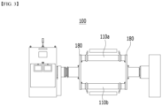
- FIG. 3 is a front view of the apparatus 100 for winding a sheet for manufacturing a secondary battery of FIG. 2 .
- FIG. 4 is a side view of the apparatus 100 for winding a sheet for manufacturing a secondary battery of FIG. 2 .
- FIG. 5 is a front view of a bobbin 110 mounted on the apparatus 100 for winding a sheet for manufacturing a secondary battery of FIG. 2 .
- the apparatus 100 for winding a sheet for manufacturing a secondary battery can be used to wind (rewind) an electrode sheet (positive electrode sheet or negative electrode sheet) on which a series of processes such as coating and drying have been completed in the secondary battery electrode manufacturing process.
- the apparatus can be used to wind (rewind) the separator sheet.
- the present disclosure is not limited thereto, and can be applied to various environments, such as being used to wind other films or sheets used during the electrode manufacturing process.
- the electrode sheet is wound will be described.
- the following explanation can be applied similarly.
- the apparatus 100 for winding a sheet for manufacturing a secondary battery includes at least two bobbins 110 on which electrode sheets are wound.
- a case including two bobbins 110 is illustrated.
- the traveling bobbin is a traveling bobbin 110a
- the standby bobbin is a standby bobbin 110b.
- the traveling bobbin 110a is a bobbin on which winding of the electrode sheet is performed.
- the standby bobbin 110b is a bobbin that is in a standby state, and then is replaced with the traveling bobbin 110a when the winding of the traveling bobbin 110a is completed, and performs the winding of the electrode sheet again in the same manner.
- the present disclosure is not limited to those described above, and the winding process may be performed simultaneously by installing a plurality of traveling bobbins 110a, and the winding process can also be performed one after another in such a manner that a plurality of standby bobbins 110b is installed, an operator mounts several standby bobbins 110b at a time on the apparatus 100 for winding a sheet for manufacturing a secondary battery, and performs winding on the next bobbin 110b if the winding on one bobbin 110 is completed.
- a film member 120 is wrapped around the outer peripheral surface of the bobbin 110 along the periphery of the bobbin 110.
- the film member 120 may be, for example, vinyl, and may also be, for example, vinyl made of PET, PP or HDPL.
- the film member 120 may be surrounded around the outer peripheral surface of the bobbin 110 multiple times.
- An adhesive member 140 is adhered to the outer peripheral surface of the film member 120 that surrounds the bobbin 110, and an electrode sheet is adhered again onto the adhesive member 140.
- the adhesive member 140 may be, for example, a double-sided tape. That is, the film member 120 (vinyl) is wrapped around the outer peripheral surface of the bobbin 110, then an adhesive member 140 (double-sided tape) is attached thereto, and an electrode sheet is wound thereon. That is, the adhesive member 140 may be provided on the outer peripheral surface of the bobbin 110 with the film member 120 interposed therebetween.
- the mark 130 is provided on the outer peripheral surface of the bobbin 110 or the outer peripheral surface of the film member 120 that surrounds the bobbin 110.
- the position at which the starting portion (start position) of the electrode sheet is attached that is, the position of the adhesive member 140, which will be described later, is determined with reference to the mark 130.
- the sensor 150 is, for example, a laser light sensor or a color sensor, and the mark 130 has a color different from the color of the outer peripheral surface of the bobbin 110 or the film member 120 so that color can be detected by the sensor 150.
- the laser light sensor it is a laser type photoelectric sensor, and recognizes the presence of the mark 130 through the intensity returned after reflection on the film member 120 with a white background and the colored mark 130. Therefore, the position of the adhesive member 140 can be identified by detecting the position of the mark 130.
- the sensor 150 is disposed near the bobbin 110 and spaced apart from the bobbin 110 by a predetermined distance.
- a mark 130 may be located along the longitudinal direction of the bobbin 110 at the end point of the film member 120.
- the mark 130 may be located on the outer peripheral surface of the bobbin 110 along the longitudinal direction of the bobbin 110, and the film member 120 may be made of a transparent material.
- the shape or form of the mark 130 is not limited, and is sufficient if it can mark the starting portion of the electrode sheet and detect the color with the sensor 150.
- the mark 130 may be a solid line or a dotted line, or may be a line that is shown wholly along the longitudinal direction of the bobbin 110. Alternatively, it may be a set of lines or dots that are only partially shown along the length direction of the bobbin 110. For example, it may be a solid line extending along the whole length direction of the bobbin 110, but can be modified and changed in various ways, such as showing a plurality of dot shapes here and there along the longitudinal direction of the bobbin 110.
- FIG. 6 is a perspective view of a bobbin according to an embodiment of the present disclosure.
- the mark 130 is a finishing sticker for fixing the film member 120.
- the adhesive member 140 may be attached to the entire outer peripheral surface of the bobbin 110.
- the electrode sheet is wound along the adhesive member 140 surrounded by the entire bobbin 110, if the electrode sheet is incorrectly attached to part or all of the adhesive member 140 and the electrode sheet is attached in a curved or uneven manner, there is a risk that the electrode roll R that is subsequently wound around the bobbin 110 may not be smooth.
- the adhesive member 140 has a band shape with a constant width, and is attached to a part of the outer peripheral surface of the bobbin 110 along the portion where the mark 130 is located apart from the mark 130 by a predetermined distance.
- the electrode sheet is fixed to the adhesive member 140 located at the mark 130, and then, when the bobbin 110 rotates while maintaining a constant tension on the electrode sheet, the electrode sheet may be smoothly wound along the periphery of the bobbin 110.
- FIG. 5 illustrates case where the adhesive member 140 is attached to a part of the outer peripheral surface of the bobbin 110 by being spaced apart from the mark 130 by a predetermined distance (e.g., 10 mm).
- a predetermined distance e.g. 10 mm
- the adhesive member 140 is attached with reference to the mark 130.
- An operator may wrap the film member 120 around the bobbin 110 in advance, attaches the adhesive member 140 thereon, and then can mount the bobbin 110 on the apparatus 100 for winding a sheet for manufacturing a secondary battery.
- the bobbin 110 is mounted on the apparatus 100 for winding a sheet for manufacturing a secondary battery, and then various modifications and changes can be made, such as the film member 120 being wrapped with a nip roller or the like provided in the apparatus 100 for winding a sheet for manufacturing a secondary battery, and being able to attach the adhesive member 140.
- the standby bobbin 110b rotates slowly, and the mark 130 on the standby bobbin 110b is detected by the sensor 150, so that the mark 130 is located at a predetermined position where it can contact the pressure member 160.
- the pressure member 160 is, for example, a nip roller.
- the mark 130 may be located so as to face the pressure member 160.
- the sensor 150 detects the color of the mark 130, the standby bobbin 110b rotates a little more for a predetermined time or at a predetermined angle, and then the mark 130 may be located so as to face the pressure member 160.
- This can be modified, changed and applied in various ways depending on various environments in which the invention is implemented, that is, the spacing arrangement between the standby bobbin 110b, the sensor 150, and the pressure member 160, and the like.
- the important point is that the mark 130 can be detected by the sensor 150, and the electrode sheet can be accurately attached to the electrode attachment position (i.e., the adhesive member 140) of the standby bobbin 110b, as described later.
- the sensor 150 may detect the mark 130 on the standby bobbin 110b, but even while the traveling bobbin 110a is winding the electrode sheet, the sensor 150 detects the mark 130 on the standby bobbin 110b in advance, and the electrode attachment position (i.e., adhesive member 140) of the standby bobbin 110b can also be kept in a standby state in advance in the direction of the electrode sheet.
- the electrode sheet passes between the pressure member 160 and the standby bobbin 110b.
- the pressure member 160 moves toward the standby bobbin 110b, the electrode sheet is attached to the adhesive member 140 of the standby bobbin 110b using the pressure member 160, and then separated from the standby bobbin 110b again.
- the electrode sheet is cut along the dotted line shown in FIG. 2 using the cutting member 170.
- the turret 180 rotates 180 degrees with reference to the central axis, and the standby bobbin 110b to which the electrode sheet is attached moves toward the existing traveling bobbin 110a to start winding the electrode sheet.
- the traveling bobbin 110a and the standby bobbin 110b are named the traveling bobbin 110a and the standby bobbin 110b, but when the standby bobbin 110b moves toward the traveling bobbin 110a and performs winding of the electrode sheet, the standby bobbin 110b in the previous winding step becomes the traveling bobbin 110a in the corresponding winding step, and the electrode roll wound onto the traveling bobbin 110a in the previous winding step is detached and transferred to the next process.
- a new bobbin 110 is installed, it becomes the standby bobbin 110b in the corresponding winding step.
- the rotation angle of the turret 180 is not limited to those described above, and can be modified or changed in accordance with various environments in which the invention is implemented.
- the number of bobbins 100, the position where the traveling bobbin 110a, which performs winding of the electrode sheet, is mounted, and the position where the standby bobbin 110b, where the electrode sheet is attached by the pressure member 160, is mounted, etc. change, it can be modified, changed, and applied in various ways.
- the apparatus 100 for winding a sheet for manufacturing a secondary battery further comprises a guide member 190 that changes or guides the movement direction of the electrode sheet.
- the number, type, position, etc. of the guide members 190 are not particularly limited, and various modifications and changes can be made in accordance with the environment in which the invention is implemented.
- the guide member 190 may be, for example, in the form of a roller.
- the guide roller 190a located in the path between the traveling bobbin 110a and the standby bobbin 110b facilitates winding in the traveling bobbin 110a, while it also makes it easy to attach the electrode sheet to the standby bobbin 110b using the pressure member 160.
- the apparatus 100 for winding a sheet for manufacturing a secondary battery may further comprise a dancer roller 190c in the path of the electrode sheet.
- the apparatus 100 for winding a sheet for manufacturing a secondary battery comprises a driving means (not shown) that drives a frame (not shown) supporting a bobbin 110 or a turret 180, and the components such as a bobbin 110, the turret 180, and the pressure member 160.
- the electrode sheets are sequentially wound up while the traveling bobbin 110a and the standby bobbin 110b rotate.
- the sheet after the winding process on one bobbin is completed, the sheet can be automatically attached to another bobbin and the winding process can be performed again, thereby reducing the time required to replace the bobbin. This improves the production efficiency of the process.
- bobbin 110a traveling bobbin 110b: standby bobbin 120: film member 130: mark 140: adhesive member 150: sensor 160: pressure member 170: cutting member 180: turret 190: guide member
Landscapes
- Manufacturing & Machinery (AREA)
- Chemical & Material Sciences (AREA)
- Chemical Kinetics & Catalysis (AREA)
- Electrochemistry (AREA)
- General Chemical & Material Sciences (AREA)
- Engineering & Computer Science (AREA)
- Secondary Cells (AREA)
- Replacement Of Web Rolls (AREA)
- Battery Electrode And Active Subsutance (AREA)
- Storage Of Web-Like Or Filamentary Materials (AREA)
- Controlling Rewinding, Feeding, Winding, Or Abnormalities Of Webs (AREA)
- Cell Separators (AREA)
- Advancing Webs (AREA)
- Winding Of Webs (AREA)
Abstract
Description
- This application claims the benefit of Korean Patent Application No.
10-2022-0142920 filed on October 31, 2022 - The present disclosure relates to an apparatus used in the process of winding a sheet for manufacturing a secondary, and more particularly, to an apparatus for winding a sheet for manufacturing a secondary battery that can automatically recognize the position where the electrode sheet or separator sheet is connected to a bobbin, and can improve the winding performance of the electrode sheet or separator sheet.
- As the price of energy sources increases due to depletion of fossil fuels and the interest in environmental pollution increases, the demand for environmentally friendly alternative energy sources becomes an indispensable factor for future life. Therefore, research into various power generation technologies such as a nuclear power generation technology, a photovoltaic power generation technology, a wind power generation technology, a tidal power generation technology, and the like, has been continuously conducted, and a power storage device for efficiently using energy thus produced has also been interested.
- Particularly, as the development of a technology and the demand for a mobile device have increased, the demand for a secondary battery as an energy source has rapidly increased, and thus, various research into secondary batteries capable of satisfying various requirements has been conducted.
- Typically, the demand for lithium secondary batteries, such as lithium ion batteries and lithium ion polymer batteries, having advantages such as high energy density, discharge voltage and power stability, is very high.
- A secondary battery may include a positive electrode and a negative electrode. The positive electrode consists of a positive electrode coated portion in which the positive electrode active material is coated onto the positive electrode current collector, and a positive electrode non-coated portion in which the positive electrode active material is not coated. Similarly, the negative electrode also consists of a negative electrode coated portion in which the negative electrode active material is coated onto the negative electrode current collector, and a negative electrode non-coated portion in which the negative electrode active material is not coated. The positive electrode non-coated portion and the negative electrode non-coated portion are provided with electrode tabs, respectively.
- A porous separator is interposed between the positive electrode and the negative electrode, and such a separator not only insulates the positive electrode and the negative electrode from each other, but also allows active material ions to be exchanged between electrodes, thereby causing an electrochemical reaction.
- Such a secondary battery is classified depending on a structure of an electrode assembly in which a positive electrode and a negative electrode are stacked with a separator being interposed between the positive electrode and the negative electrode. A representative example of the electrode assembly includes a jelly-roll type (wound type) electrode assembly having a structure in which long sheet-type positive and negative electrodes are wound with a separator being interposed therebetween, a stack type (stacked type) electrode assembly having a structure in which a plurality of positive and negative electrodes that are cut at a predetermined size unit are sequentially stacked with a separator being interposed therebetween, and the like. Recently, in order to solve problems of the jelly-roll type electrode assembly and the stack type electrode assembly, as an electrode assembly of a mixed type of the jelly-roll type and the stack type, a stacked/folding type electrode assembly having a structure in which unit cells in which positive and negative electrodes of a predetermined unit are stacked with a separator therebetween are sequentially wound while being positioned on a separation film, has been developed.
- On the other hand, each electrode constituting the electrode assembly is manufactured in the form of a sheet and provided to the secondary battery manufacturing process. Typically, the electrode sheet that has gone through the electrode manufacturing process is wound in the form of a roll on a predetermined bobbin. The electrode sheet is wound around the bobbin while being supported by a final bobbin disposed at the front position of the bobbin.
- Referring to
FIG. 1 , in aconventional apparatus 1 for winding a sheet for manufacturing a secondary battery, a double-sided tape 30 is attached to a line-shaped mark 20 where the starting portion of the electrode sheet is attached to abobbin 10. Further, in order to ensure that the starting portion of the electrode sheet on thebobbin 10 is accurately attached to themark 20, at least one of the twomounting members 40 on both sides of thebobbin 10 is provided with a convex-shaped dog 50 that guides the starting portion of the electrode sheet, and thedog 50 is located on an extension line of themark 20. An operator mounts thebobbin 10 on theapparatus 1 winding a sheet for manufacturing a secondary battery, and rotates thedog 50 so that themark 20 of thebobbin 10 is placed in front of the operator. Further, the operator aligns the starting portion of the electrode sheet to themark 20 and then manually attaches the electrode sheet to the double-sided tape 30 on the surface of thebobbin 10. Subsequently, the winding process of the electrode sheet proceeds. - There is a need to convert a
conventional apparatus 1, in which a sheet for manufacturing a secondary battery winds in a manual manner, to an automated process manner to thereby increase the convenience and efficiency of the process. - It is an object of the present disclosure to provide an apparatus for winding a sheet for manufacturing a secondary battery, having a structure which can automatically recognize the attachment position of a sheet to a bobbin used in the winding process of a secondary battery manufacturing sheet (electrode sheet or separator sheet), and also can automatically attach the sheet to the bobbin to wind the sheet.
- It is another object of the present disclosure to increase the convenience and efficiency of the process by using such an apparatus for winding a sheet for manufacturing a secondary battery, and also reducing the defective rate of the electrode winding roll by attaching the electrode roll to an accurate position.
- However, the technical problems to be solved by the embodiments of the present disclosure are not limited to the above-described problems, and can be variously expanded within the scope of the technical idea included in the present disclosure.
- According to one aspect of the present disclosure, there is provided an apparatus for winding a sheet for manufacturing a secondary battery, the apparatus comprising: at least two bobbins including a traveling bobbin on which a winding process proceeds and a standby bobbin that is in a standby state during the winding process; and a sensor that is disposed apart from the standby bobbin by a predetermined distance and detects a mark for identifying a position where the sheet wound onto the traveling bobbin will be automatically attached to the standby bobbin, wherein when the winding process on the traveling bobbin is completed, the sheet that was wound by the traveling bobbin is attached to an outer peripheral surface of the standby bobbin, and subsequently the winding process is performed.
- By detecting the mark by the sensor may allow the position where the sheet of the standby bobbin is attached may be directed toward the sheet.
- An adhesive member to which a start position of the sheet is attached is provided on the outer peripheral surface of the standby bobbin, and when detecting the mark by the sensor, the sheet may be attached onto the adhesive member of the standby bobbin.
- The apparatus further comprises a turret that supports the traveling bobbin and the standby bobbin, and rotates the traveling bobbin and the standby bobbin, wherein, when the winding process on the traveling bobbin is completed by rotation of the turret, the winding process on the standby bobbin is subsequently performed.
- The sheet passes between the standby bobbin and the pressure member and moves, and is wound onto the traveling bobbin, and when the winding process on the traveling bobbin is completed, the sheet is attached to the outer peripheral surface of the standby bobbin with the pressure member, cuts with a cutting member, and the winding process on the standby bobbin may be then performed.
- When the winding of the sheet of the traveling bobbin is completed, the sensor may detect a mark on the standby bobbin.
- During the winding process on the traveling bobbin, the sensor may previously detect the mark on the standby bobbin.
- When the winding process on the traveling bobbin is completed, the apparatus may further comprise a pressure member that attaches the sheet to the outer peripheral surface of the standby bobbin.
- The mark has a color that is distinguished from the outer peripheral surface of the standby bobbin, and the sensor may be a laser light sensor or a color sensor.
- The adhesive member has a band shape and is located along the longitudinal direction of the bobbin, and the adhesive member may be located in contact with the mark or apart from the mark by a predetermined distance.
- The outer peripheral surface of the standby bobbin is surrounded by a film member, and the adhesive member may be attached onto the film member.
- The film member may be PET, PP, or HDPL vinyl.
- The mark may be a finishing tape that finishes and secures an end position of the film member.
- The pressure member may be a nip roller that is reciprocally movable toward the standby bobbin.
- The apparatus may further comprise a guide member that changes or guides the moving direction of the sheet.
- The guide member further comprises a first guide member located on a movement path between the traveling bobbin and the standby bobbin of the sheet, wherein a tension of the sheet between the traveling bobbin and the first guide member may be maintained by the first guide member, and a tension of the sheet between the first guide member and the standby bobbin may be maintained by the first guide member.
- The first guide member may be a guide roller.
- The first guide member may further comprise a dancer roller.
- The mark may be a line that is shown wholly along the longitudinal direction of the bobbin, or a set of lines or dots that are only partially shown along the longitudinal direction of the bobbin.
- The sheet may be any one of a positive electrode sheet, a negative electrode sheet, and a separator sheet of a secondary battery.
- The present disclosure automatically recognizes the attachment position of a sheet to a bobbin used in the winding process of a secondary battery manufacturing sheet (electrode sheet or separator sheet), and automatically attaches the sheet to the bobbin, which increases the convenience and efficiency of the process, while it has the advantage of significantly lowering the defective rate of the electrode winding roll by attaching the electrode roll to an accurate position even in such an automated process.
-
-
FIG. 1 is a diagram schematically showing an apparatus for winding a sheet for manufacturing a secondary battery according to the prior art; -
FIG. 2 is a diagram schematically showing an apparatus for winding a sheet for manufacturing a secondary battery according to an embodiment of the present disclosure; -
FIG. 3 is a front view of the apparatus for winding a sheet for manufacturing a secondary battery ofFIG. 2 ; -
FIG. 4 is a side view of the apparatus for winding a sheet for manufacturing a secondary battery ofFIG. 2 ; -
FIG. 5 is a front view of a bobbin mounted on the apparatus for winding a sheet for manufacturing a secondary battery ofFIG. 2 ; and -
FIG. 6 is a perspective view of a bobbin according to an embodiment of the present disclosure. - Hereinafter, various embodiments of the present disclosure will be described in detail with reference to the accompanying drawings so that those skilled in the art can easily carry out them. The present disclosure can be modified in various different ways, and is not limited to the embodiments set forth herein.
- A description of portions that are irrelevant to the description will be omitted for clarity, and like reference numerals designate like elements throughout the description.
- Further, since the size and thickness of each element shown in the accompanying drawing are arbitrarily illustrated for convenience of explanation, it would be obvious that the present disclosure is not necessarily limited to those illustrated in the drawings. In the drawings, the thickness are exaggerated for clearly expressing several layers and regions. In the drawings, for convenience of explanation, the thicknesses of some layer and regions are exaggerated.
- Further, it will be understood that when an element such as a layer, film, region, or plate is referred to as being "on" or "above" another element, it can be directly on the other element or intervening elements may also be present. In contrast, when an element is referred to as being "directly on" another element, it means that other intervening elements are not present. Further, a certain part being located "above" or "on" a reference portion means the certain part being located above or below the reference portion and does not necessarily mean the certain part "above" or "on" toward an opposite direction of gravity.
- Further, throughout the description, when a portion is referred to as "including" or "comprising" a certain component, it means that the portion can further include other components, without excluding the other components, unless otherwise stated.
- Further, throughout the description, when it is referred to as "planar", it means when a target portion is viewed from the upper side, and when it is referred to as "cross-sectional", it means when a target portion is viewed from the side of a cross section cut vertically.
- Further, since the upper surface/lower surface or the upper part/lower part of a specific member can be determined differently depending on which direction is used as a reference, throughout the description, 'upper surface' or 'lower surface' are defined as meaning two facing surfaces on the z-axis of the corresponding member, and the 'upper part' and 'lower part' are defined as disposing opposite directions to each other on the z-axis of the corresponding member,
-
FIG. 2 is a diagram schematically showing anapparatus 100 for winding a sheet for manufacturing a secondary battery according to an embodiment of the present disclosure.FIG. 3 is a front view of theapparatus 100 for winding a sheet for manufacturing a secondary battery ofFIG. 2 .FIG. 4 is a side view of theapparatus 100 for winding a sheet for manufacturing a secondary battery ofFIG. 2 .FIG. 5 is a front view of abobbin 110 mounted on theapparatus 100 for winding a sheet for manufacturing a secondary battery ofFIG. 2 . - The
apparatus 100 for winding a sheet for manufacturing a secondary battery according to an embodiment of the present disclosure can be used to wind (rewind) an electrode sheet (positive electrode sheet or negative electrode sheet) on which a series of processes such as coating and drying have been completed in the secondary battery electrode manufacturing process. Alternatively, the apparatus can be used to wind (rewind) the separator sheet. However, the present disclosure is not limited thereto, and can be applied to various environments, such as being used to wind other films or sheets used during the electrode manufacturing process.
Hereinafter, for convenience of explanation, a case where the electrode sheet is wound will be described. When winding other sheets such as separator sheets, the following explanation can be applied similarly. - Referring to
FIGS. 2 to 5 , theapparatus 100 for winding a sheet for manufacturing a secondary battery according to an embodiment of the present disclosure includes at least twobobbins 110 on which electrode sheets are wound. In the present embodiment, a case including twobobbins 110 is illustrated. - Among the two
bobbins 110, the traveling bobbin is a travelingbobbin 110a, and the standby bobbin is astandby bobbin 110b. The travelingbobbin 110a is a bobbin on which winding of the electrode sheet is performed. Thestandby bobbin 110b is a bobbin that is in a standby state, and then is replaced with the travelingbobbin 110a when the winding of the travelingbobbin 110a is completed, and performs the winding of the electrode sheet again in the same manner. - Meanwhile, the present disclosure is not limited to those described above, and the winding process may be performed simultaneously by installing a plurality of traveling
bobbins 110a, and the winding process can also be performed one after another in such a manner that a plurality ofstandby bobbins 110b is installed, an operator mountsseveral standby bobbins 110b at a time on theapparatus 100 for winding a sheet for manufacturing a secondary battery, and performs winding on thenext bobbin 110b if the winding on onebobbin 110 is completed. - A
film member 120 is wrapped around the outer peripheral surface of thebobbin 110 along the periphery of thebobbin 110. Thefilm member 120 may be, for example, vinyl, and may also be, for example, vinyl made of PET, PP or HDPL. Thefilm member 120 may be surrounded around the outer peripheral surface of thebobbin 110 multiple times. Anadhesive member 140 is adhered to the outer peripheral surface of thefilm member 120 that surrounds thebobbin 110, and an electrode sheet is adhered again onto theadhesive member 140. Theadhesive member 140 may be, for example, a double-sided tape. That is, the film member 120 (vinyl) is wrapped around the outer peripheral surface of thebobbin 110, then an adhesive member 140 (double-sided tape) is attached thereto, and an electrode sheet is wound thereon. That is, theadhesive member 140 may be provided on the outer peripheral surface of thebobbin 110 with thefilm member 120 interposed therebetween. - This prevents the surface of the
bobbin 110 from being contaminated by theadhesive member 140, and allows thebobbin 110 to be repeatedly reused. - On the other hand, the
mark 130 is provided on the outer peripheral surface of thebobbin 110 or the outer peripheral surface of thefilm member 120 that surrounds thebobbin 110. The position at which the starting portion (start position) of the electrode sheet is attached, that is, the position of theadhesive member 140, which will be described later, is determined with reference to themark 130. Thesensor 150 is, for example, a laser light sensor or a color sensor, and themark 130 has a color different from the color of the outer peripheral surface of thebobbin 110 or thefilm member 120 so that color can be detected by thesensor 150. In the case of the laser light sensor, it is a laser type photoelectric sensor, and recognizes the presence of themark 130 through the intensity returned after reflection on thefilm member 120 with a white background and thecolored mark 130. Therefore, the position of theadhesive member 140 can be identified by detecting the position of themark 130. Thesensor 150 is disposed near thebobbin 110 and spaced apart from thebobbin 110 by a predetermined distance. - When the
film member 120 surrounds thebobbin 110, amark 130 may be located along the longitudinal direction of thebobbin 110 at the end point of thefilm member 120. Alternatively, themark 130 may be located on the outer peripheral surface of thebobbin 110 along the longitudinal direction of thebobbin 110, and thefilm member 120 may be made of a transparent material. - Further, the shape or form of the
mark 130 is not limited, and is sufficient if it can mark the starting portion of the electrode sheet and detect the color with thesensor 150. Themark 130 may be a solid line or a dotted line, or may be a line that is shown wholly along the longitudinal direction of thebobbin 110. Alternatively, it may be a set of lines or dots that are only partially shown along the length direction of thebobbin 110. For example, it may be a solid line extending along the whole length direction of thebobbin 110, but can be modified and changed in various ways, such as showing a plurality of dot shapes here and there along the longitudinal direction of thebobbin 110. -
FIG. 6 is a perspective view of a bobbin according to an embodiment of the present disclosure. In the present embodiment, a case is illustrated in which themark 130 is a finishing sticker for fixing thefilm member 120. - On the other hand, the
adhesive member 140 may be attached to the entire outer peripheral surface of thebobbin 110. In this case, in case where the electrode sheet is wound along theadhesive member 140 surrounded by theentire bobbin 110, if the electrode sheet is incorrectly attached to part or all of theadhesive member 140 and the electrode sheet is attached in a curved or uneven manner, there is a risk that the electrode roll R that is subsequently wound around thebobbin 110 may not be smooth. - Referring again to
FIGS. 2 to 5 , it is more preferable that theadhesive member 140 has a band shape with a constant width, and is attached to a part of the outer peripheral surface of thebobbin 110 along the portion where themark 130 is located apart from themark 130 by a predetermined distance. In the latter case, as described later, the electrode sheet is fixed to theadhesive member 140 located at themark 130, and then, when thebobbin 110 rotates while maintaining a constant tension on the electrode sheet, the electrode sheet may be smoothly wound along the periphery of thebobbin 110. -
FIG. 5 illustrates case where theadhesive member 140 is attached to a part of the outer peripheral surface of thebobbin 110 by being spaced apart from themark 130 by a predetermined distance (e.g., 10 mm). - For example, as illustrated in
FIG. 5 , theadhesive member 140 is attached with reference to themark 130. An operator may wrap thefilm member 120 around thebobbin 110 in advance, attaches theadhesive member 140 thereon, and then can mount thebobbin 110 on theapparatus 100 for winding a sheet for manufacturing a secondary battery. Alternatively, thebobbin 110 is mounted on theapparatus 100 for winding a sheet for manufacturing a secondary battery, and then various modifications and changes can be made, such as thefilm member 120 being wrapped with a nip roller or the like provided in theapparatus 100 for winding a sheet for manufacturing a secondary battery, and being able to attach theadhesive member 140. - Referring to
FIG. 2 , a method of winding an electrode sheet onto the travelingbobbin 110a and then winding it again onto thestandby bobbin 110b in the same manner will be described. When the winding of the electrode sheet onto the runningbobbin 110a is completed, the following operation is performed in order to subsequently attach the electrode sheet to thestandby bobbin 110b. - First, the
standby bobbin 110b rotates slowly, and themark 130 on thestandby bobbin 110b is detected by thesensor 150, so that themark 130 is located at a predetermined position where it can contact thepressure member 160. Thepressure member 160 is, for example, a nip roller. - As the
sensor 150 detects the color of themark 130, themark 130 may be located so as to face thepressure member 160. Alternatively, thesensor 150 detects the color of themark 130, thestandby bobbin 110b rotates a little more for a predetermined time or at a predetermined angle, and then themark 130 may be located so as to face thepressure member 160. This can be modified, changed and applied in various ways depending on various environments in which the invention is implemented, that is, the spacing arrangement between thestandby bobbin 110b, thesensor 150, and thepressure member 160, and the like. The important point is that themark 130 can be detected by thesensor 150, and the electrode sheet can be accurately attached to the electrode attachment position (i.e., the adhesive member 140) of thestandby bobbin 110b, as described later. - Further, when the winding of the electrode sheet on the traveling
bobbin 110a is completed, thesensor 150 may detect themark 130 on thestandby bobbin 110b, but even while the travelingbobbin 110a is winding the electrode sheet, thesensor 150 detects themark 130 on thestandby bobbin 110b in advance, and the electrode attachment position (i.e., adhesive member 140) of thestandby bobbin 110b can also be kept in a standby state in advance in the direction of the electrode sheet. - The electrode sheet passes between the
pressure member 160 and thestandby bobbin 110b. Thepressure member 160 moves toward thestandby bobbin 110b, the electrode sheet is attached to theadhesive member 140 of thestandby bobbin 110b using thepressure member 160, and then separated from thestandby bobbin 110b again. At this time, the electrode sheet is cut along the dotted line shown inFIG. 2 using the cuttingmember 170. - On the other hand, the
turret 180 rotates 180 degrees with reference to the central axis, and thestandby bobbin 110b to which the electrode sheet is attached moves toward the existing travelingbobbin 110a to start winding the electrode sheet. For convenience of explanation, they are named the travelingbobbin 110a and thestandby bobbin 110b, but when thestandby bobbin 110b moves toward the travelingbobbin 110a and performs winding of the electrode sheet, thestandby bobbin 110b in the previous winding step becomes the travelingbobbin 110a in the corresponding winding step, and the electrode roll wound onto the travelingbobbin 110a in the previous winding step is detached and transferred to the next process. When anew bobbin 110 is installed, it becomes thestandby bobbin 110b in the corresponding winding step. - The rotation angle of the
turret 180 is not limited to those described above, and can be modified or changed in accordance with various environments in which the invention is implemented. For example, as the number ofbobbins 100, the position where the travelingbobbin 110a, which performs winding of the electrode sheet, is mounted, and the position where thestandby bobbin 110b, where the electrode sheet is attached by thepressure member 160, is mounted, etc. change, it can be modified, changed, and applied in various ways. - The
apparatus 100 for winding a sheet for manufacturing a secondary battery further comprises aguide member 190 that changes or guides the movement direction of the electrode sheet. The number, type, position, etc. of theguide members 190 are not particularly limited, and various modifications and changes can be made in accordance with the environment in which the invention is implemented. Theguide member 190 may be, for example, in the form of a roller. Theguide roller 190a located in the path between the travelingbobbin 110a and thestandby bobbin 110b facilitates winding in the travelingbobbin 110a, while it also makes it easy to attach the electrode sheet to thestandby bobbin 110b using thepressure member 160. In addition, theguide roller 190a supports the electrode sheet and maintains the tension of the electrode sheet, thereby preventing the travelingbobbin 110a and thestandby bobbin 110b from unintentionally influencing each other due to the above-described operations. Theapparatus 100 for winding a sheet for manufacturing a secondary battery may further comprise adancer roller 190c in the path of the electrode sheet. - Further, the
apparatus 100 for winding a sheet for manufacturing a secondary battery comprises a driving means (not shown) that drives a frame (not shown) supporting abobbin 110 or aturret 180, and the components such as abobbin 110, theturret 180, and thepressure member 160. - In the above-described manner, the electrode sheets are sequentially wound up while the traveling
bobbin 110a and thestandby bobbin 110b rotate. - According to the present disclosure described above, after the winding process on one bobbin is completed, the sheet can be automatically attached to another bobbin and the winding process can be performed again, thereby reducing the time required to replace the bobbin. This improves the production efficiency of the process.
- It will be apparent to those skilled in the art that various modifications and variations can be made in the present disclosure without departing from the spirit and scope of the present disclosure.
- Although preferred embodiments of the present disclosure have been described in detail above, the scope of the present disclosure is not limited thereto, and various modifications and improvements can be made by those skilled in the art using the basic concepts of the present disclosure as defined in the appended claims, which also falls within the scope of the present disclosure.
- 100: apparatus for winding a sheet for manufacturing a secondary battery 110: bobbin 110a: traveling
bobbin 110b: standby bobbin 120: film member 130: mark 140: adhesive member 150: sensor 160: pressure member 170: cutting member 180: turret 190: guide member
Claims (20)
- An apparatus for winding a sheet for manufacturing a secondary battery, the apparatus comprising:at least two bobbins including a traveling bobbin on which a winding process proceeds and a standby bobbin that is in a standby state during the winding process; anda sensor that is disposed apart from the standby bobbin by a predetermined distance and detects a mark for identifying a position where the sheet wound onto the traveling bobbin will be automatically attached to the standby bobbin,wherein when the winding process on the traveling bobbin is completed, the sheet that was wound by the traveling bobbin is attached to an outer peripheral surface of the standby bobbin, and subsequently the winding process is performed.
- The apparatus for winding a sheet for manufacturing a secondary battery according to claim 1, wherein:
the sheet is any one of a positive electrode sheet, a negative electrode sheet, and a separator sheet of a secondary battery. - The apparatus for winding a sheet for manufacturing a secondary battery according to claim 1, wherein:
by detecting the mark by the sensor, the position where the sheet of the standby bobbin will be attached is directed toward the sheet. - The apparatus for winding a sheet for manufacturing a secondary battery according to claim 1, wherein:an adhesive member to which a start position of the sheet is attached is provided on the outer peripheral surface of the standby bobbin, andwhen detecting the mark by the sensor, the sheet is attached onto the adhesive member of the standby bobbin.
- The apparatus for winding a sheet for manufacturing a secondary battery according to claim 1, further comprising:a turret that supports the traveling bobbin and the standby bobbin, and rotates the traveling bobbin and the standby bobbin,wherein, when the winding process on the traveling bobbin is completed by rotation of the turret, the winding process on the standby bobbin is subsequently performed.
- The apparatus for winding a sheet for manufacturing a secondary battery according to claim 1, wherein:the sheet passes between the standby bobbin and the pressure member and moves, and is wound onto the traveling bobbin, andwhen the winding process on the traveling bobbin is completed, the sheet is attached to the outer peripheral surface of the standby bobbin with the pressure member, cuts with a cutting member, and the winding process on the standby bobbin is then performed.
- The apparatus for winding a sheet for manufacturing a secondary battery according to claim 1, wherein:
when the winding of the sheet of the traveling bobbin is completed, the sensor detects a mark on the standby bobbin. - The apparatus for winding a sheet for manufacturing a secondary battery according to claim 1, wherein:
during the winding process on the traveling bobbin, the sensor previously detects the mark on the standby bobbin. - The apparatus for winding a sheet for manufacturing a secondary battery according to claim 1, wherein:
when the winding process on the traveling bobbin is completed, the apparatus further comprises a pressure member that attaches the sheet to the outer peripheral surface of the standby bobbin. - The apparatus for winding a sheet for manufacturing a secondary battery according to claim 1, wherein:the mark has a color that is distinguished from the outer peripheral surface of the standby bobbin, andthe sensor is a laser light sensor or a color sensor.
- The apparatus for winding a sheet for manufacturing a secondary battery according to claim 4, wherein:the adhesive member has a band shape and is located along the longitudinal direction of the bobbin, andthe adhesive member is located in contact with the mark or apart from the mark by a predetermined distance.
- The apparatus for winding a sheet for manufacturing a secondary battery according to claim 4, wherein:the outer peripheral surface of the standby bobbin is surrounded by a film member, andthe adhesive member is attached onto the film member.
- The apparatus for winding a sheet for manufacturing a secondary battery according to claim 12, wherein:
the film member is PET, PP, or HDPL vinyl. - The apparatus for winding a sheet for manufacturing a secondary battery according to claim 12, wherein:
the mark is a finishing tape that finishes and secures an end position of the film member. - The apparatus for winding a sheet for manufacturing a secondary battery according to claim 1, wherein:
the pressure member is a nip roller that is reciprocally movable toward the standby bobbin. - The apparatus for winding a sheet for manufacturing a secondary battery according to claim 1, further comprising:
a guide member that changes or guides the moving direction of the sheet. - The apparatus for winding a sheet for manufacturing a secondary battery according to claim 16, wherein:the guide member further comprises a first guide member located on a movement path between the traveling bobbin and the standby bobbin of the sheet,wherein a tension of the sheet between the traveling bobbin and the first guide member is maintained by the first guide member, and a tension of the sheet between the first guide member and the standby bobbin is maintained by the first guide member.
- The apparatus for winding a sheet for manufacturing a secondary battery according to claim 17, wherein:
the first guide member is a guide roller. - The apparatus for winding a sheet for manufacturing a secondary battery according to claim 16, wherein:
the first guide member further comprises a dancer roller. - The apparatus for winding a sheet for manufacturing a secondary battery according to claim 1, wherein:
the mark is a line that is shown wholly along the longitudinal direction of the bobbin, or a set of lines or dots that are only partially shown along the longitudinal direction of the bobbin.
Applications Claiming Priority (2)
| Application Number | Priority Date | Filing Date | Title |
|---|---|---|---|
| KR1020220142920A KR20240062387A (en) | 2022-10-31 | 2022-10-31 | An apparatus for winding a sheet for manufacturing a secondary battery |
| PCT/KR2023/016654 WO2024096431A1 (en) | 2022-10-31 | 2023-10-25 | Sheet winding device for manufacturing secondary battery |
Publications (2)
| Publication Number | Publication Date |
|---|---|
| EP4576292A1 true EP4576292A1 (en) | 2025-06-25 |
| EP4576292A4 EP4576292A4 (en) | 2025-12-03 |
Family
ID=90930975
Family Applications (1)
| Application Number | Title | Priority Date | Filing Date |
|---|---|---|---|
| EP23886127.2A Pending EP4576292A4 (en) | 2022-10-31 | 2023-10-25 | FOIL WINDING DEVICE FOR THE MANUFACTURING OF A SECONDARY BATTERY |
Country Status (6)
| Country | Link |
|---|---|
| US (1) | US20260100401A1 (en) |
| EP (1) | EP4576292A4 (en) |
| JP (1) | JP2025532498A (en) |
| KR (1) | KR20240062387A (en) |
| CN (1) | CN119856314A (en) |
| WO (1) | WO2024096431A1 (en) |
Family Cites Families (12)
| Publication number | Priority date | Publication date | Assignee | Title |
|---|---|---|---|---|
| JP3506818B2 (en) * | 1995-08-23 | 2004-03-15 | 東芝電池株式会社 | Device and method for winding electrode sheet for battery |
| JP4964821B2 (en) * | 2008-04-21 | 2012-07-04 | シーケーディ株式会社 | Winding device and winding element manufacturing method |
| JP5670973B2 (en) * | 2012-08-20 | 2015-02-18 | Ckd株式会社 | Winding device |
| KR102177507B1 (en) * | 2015-06-19 | 2020-11-11 | 삼성에스디아이 주식회사 | A system for rolling electrode plate |
| JP6713278B2 (en) * | 2015-12-25 | 2020-06-24 | Ckd株式会社 | Winding device and method of manufacturing wound body |
| KR101810143B1 (en) * | 2016-07-21 | 2017-12-19 | (주)피엔티 | Apparatus for pressing and slitting electrode of secondary battery |
| JP6525943B2 (en) * | 2016-11-08 | 2019-06-05 | Ckd株式会社 | Winding device |
| KR101963740B1 (en) * | 2017-11-07 | 2019-03-29 | (주)피토 | Apparatus for Manufacturing Secondary Batter |
| JP2021187579A (en) * | 2020-05-26 | 2021-12-13 | 住友化学株式会社 | Film winder and method of making film-wound body |
| JP2021187580A (en) * | 2020-05-26 | 2021-12-13 | 住友化学株式会社 | Method and apparatus for making film-wound body |
| EP4047675A1 (en) * | 2021-02-23 | 2022-08-24 | Siemens Aktiengesellschaft | A cutting system, control method, controller in a li-ion battery winding machine and medium |
| KR102702602B1 (en) | 2021-04-15 | 2024-09-04 | 황희석 | Video class system and the driving methode |
-
2022
- 2022-10-31 KR KR1020220142920A patent/KR20240062387A/en active Pending
-
2023
- 2023-10-25 WO PCT/KR2023/016654 patent/WO2024096431A1/en not_active Ceased
- 2023-10-25 CN CN202380065394.6A patent/CN119856314A/en active Pending
- 2023-10-25 US US19/112,706 patent/US20260100401A1/en active Pending
- 2023-10-25 EP EP23886127.2A patent/EP4576292A4/en active Pending
- 2023-10-25 JP JP2025513428A patent/JP2025532498A/en active Pending
Also Published As
| Publication number | Publication date |
|---|---|
| US20260100401A1 (en) | 2026-04-09 |
| WO2024096431A1 (en) | 2024-05-10 |
| JP2025532498A (en) | 2025-10-01 |
| CN119856314A (en) | 2025-04-18 |
| EP4576292A4 (en) | 2025-12-03 |
| KR20240062387A (en) | 2024-05-09 |
Similar Documents
| Publication | Publication Date | Title |
|---|---|---|
| EP4102605B1 (en) | Electrode sheet rewinding apparatus including idle roller capable of positional movement | |
| KR20220061218A (en) | Method and device for manufacturing electrode assembly of secondary battery | |
| KR20210058130A (en) | Electrode automatic supply device for secondary battery manufacturing and electrode automatic supply method using the same | |
| EP4299494B1 (en) | Winding apparatus and winding method for electrode connection film and electrode roll | |
| CN212434665U (en) | Wide-width ultrathin lithium foil and equipment for preparing wide-width ultrathin lithium foil | |
| EP4576292A1 (en) | Sheet winding device for manufacturing secondary battery | |
| US12046739B2 (en) | Electrode notching device for secondary battery, electrode for secondary battery manufactured therethrough, and secondary battery | |
| CN117790876A (en) | Battery cell winding equipment and method | |
| US12597626B2 (en) | Apparatus for adhering of tape for rechargeable battery and method using the same | |
| CN115244730B (en) | Electrode sheet connection method and electrode sheet | |
| JP2017220356A (en) | Marking device | |
| KR20240152618A (en) | Lamination device and manufacturing method thereof | |
| EP4148877A1 (en) | Method for adhering of tape for secondary battery | |
| KR20250053328A (en) | Supplying separator device and Supplying Method using the same | |
| KR102818353B1 (en) | Winding apparatus of electrode assembly and winding method of electrode assembly | |
| CN224082429U (en) | Fuel cell bilayer frame fabrication equipment and membrane electrode production equipment | |
| KR20210052914A (en) | Manufacturing Method and Manufacturing Apparatus of Electrode for Secondary Battery | |
| KR20240030677A (en) | Device for marcking on a tape for secondary battery | |
| CN224074498U (en) | membrane cutting device | |
| US20250140889A1 (en) | Sheet connection device and method for secondary battery | |
| KR20240050027A (en) | Electrode winding device | |
| JP2006168875A (en) | Grooved winding core and its holder, and method for holding a grooved winding core by a holder | |
| KR20250059186A (en) | Apparatus of manufacturing electrode assembly and method of manufacturing electrode assembly | |
| CN120109219A (en) | Fuel cell double-layer frame preparation equipment and membrane electrode production equipment | |
| CN121219876A (en) | Electrode assembly manufacturing apparatus and electrode assembly manufacturing method |
Legal Events
| Date | Code | Title | Description |
|---|---|---|---|
| STAA | Information on the status of an ep patent application or granted ep patent |
Free format text: STATUS: THE INTERNATIONAL PUBLICATION HAS BEEN MADE |
|
| PUAI | Public reference made under article 153(3) epc to a published international application that has entered the european phase |
Free format text: ORIGINAL CODE: 0009012 |
|
| STAA | Information on the status of an ep patent application or granted ep patent |
Free format text: STATUS: REQUEST FOR EXAMINATION WAS MADE |
|
| 17P | Request for examination filed |
Effective date: 20250317 |
|
| AK | Designated contracting states |
Kind code of ref document: A1 Designated state(s): AL AT BE BG CH CY CZ DE DK EE ES FI FR GB GR HR HU IE IS IT LI LT LU LV MC ME MK MT NL NO PL PT RO RS SE SI SK SM TR |
|
| A4 | Supplementary search report drawn up and despatched |
Effective date: 20251104 |
|
| RIC1 | Information provided on ipc code assigned before grant |
Ipc: H01M 10/04 20060101AFI20251029BHEP Ipc: H01M 10/0587 20100101ALI20251029BHEP |
|
| DAV | Request for validation of the european patent (deleted) | ||
| DAX | Request for extension of the european patent (deleted) |