EP4576282A1 - Coolant de-gas device and fuel cell stack - Google Patents
Coolant de-gas device and fuel cell stack Download PDFInfo
- Publication number
- EP4576282A1 EP4576282A1 EP23217831.9A EP23217831A EP4576282A1 EP 4576282 A1 EP4576282 A1 EP 4576282A1 EP 23217831 A EP23217831 A EP 23217831A EP 4576282 A1 EP4576282 A1 EP 4576282A1
- Authority
- EP
- European Patent Office
- Prior art keywords
- coolant
- channel
- gas
- isolator plate
- fuel cell
- Prior art date
- Legal status (The legal status is an assumption and is not a legal conclusion. Google has not performed a legal analysis and makes no representation as to the accuracy of the status listed.)
- Pending
Links
Images




Classifications
-
- H—ELECTRICITY
- H01—ELECTRIC ELEMENTS
- H01M—PROCESSES OR MEANS, e.g. BATTERIES, FOR THE DIRECT CONVERSION OF CHEMICAL ENERGY INTO ELECTRICAL ENERGY
- H01M8/00—Fuel cells; Manufacture thereof
- H01M8/04—Auxiliary arrangements, e.g. for control of pressure or for circulation of fluids
- H01M8/04007—Auxiliary arrangements, e.g. for control of pressure or for circulation of fluids related to heat exchange
- H01M8/04044—Purification of heat exchange media
-
- H—ELECTRICITY
- H01—ELECTRIC ELEMENTS
- H01M—PROCESSES OR MEANS, e.g. BATTERIES, FOR THE DIRECT CONVERSION OF CHEMICAL ENERGY INTO ELECTRICAL ENERGY
- H01M8/00—Fuel cells; Manufacture thereof
- H01M8/04—Auxiliary arrangements, e.g. for control of pressure or for circulation of fluids
- H01M8/04007—Auxiliary arrangements, e.g. for control of pressure or for circulation of fluids related to heat exchange
- H01M8/04014—Heat exchange using gaseous fluids; Heat exchange by combustion of reactants
-
- B—PERFORMING OPERATIONS; TRANSPORTING
- B01—PHYSICAL OR CHEMICAL PROCESSES OR APPARATUS IN GENERAL
- B01D—SEPARATION
- B01D19/00—Degasification of liquids
-
- H—ELECTRICITY
- H01—ELECTRIC ELEMENTS
- H01M—PROCESSES OR MEANS, e.g. BATTERIES, FOR THE DIRECT CONVERSION OF CHEMICAL ENERGY INTO ELECTRICAL ENERGY
- H01M8/00—Fuel cells; Manufacture thereof
- H01M8/02—Details
-
- H—ELECTRICITY
- H01—ELECTRIC ELEMENTS
- H01M—PROCESSES OR MEANS, e.g. BATTERIES, FOR THE DIRECT CONVERSION OF CHEMICAL ENERGY INTO ELECTRICAL ENERGY
- H01M8/00—Fuel cells; Manufacture thereof
- H01M8/04—Auxiliary arrangements, e.g. for control of pressure or for circulation of fluids
- H01M8/04007—Auxiliary arrangements, e.g. for control of pressure or for circulation of fluids related to heat exchange
- H01M8/04029—Heat exchange using liquids
-
- H—ELECTRICITY
- H01—ELECTRIC ELEMENTS
- H01M—PROCESSES OR MEANS, e.g. BATTERIES, FOR THE DIRECT CONVERSION OF CHEMICAL ENERGY INTO ELECTRICAL ENERGY
- H01M8/00—Fuel cells; Manufacture thereof
- H01M8/04—Auxiliary arrangements, e.g. for control of pressure or for circulation of fluids
- H01M8/04007—Auxiliary arrangements, e.g. for control of pressure or for circulation of fluids related to heat exchange
- H01M8/04067—Heat exchange or temperature measuring elements, thermal insulation, e.g. heat pipes, heat pumps, fins
-
- H—ELECTRICITY
- H01—ELECTRIC ELEMENTS
- H01M—PROCESSES OR MEANS, e.g. BATTERIES, FOR THE DIRECT CONVERSION OF CHEMICAL ENERGY INTO ELECTRICAL ENERGY
- H01M8/00—Fuel cells; Manufacture thereof
- H01M8/04—Auxiliary arrangements, e.g. for control of pressure or for circulation of fluids
- H01M8/04298—Processes for controlling fuel cells or fuel cell systems
- H01M8/04694—Processes for controlling fuel cells or fuel cell systems characterised by variables to be controlled
- H01M8/04746—Pressure; Flow
- H01M8/04776—Pressure; Flow at auxiliary devices, e.g. reformer, compressor, burner
-
- H—ELECTRICITY
- H01—ELECTRIC ELEMENTS
- H01M—PROCESSES OR MEANS, e.g. BATTERIES, FOR THE DIRECT CONVERSION OF CHEMICAL ENERGY INTO ELECTRICAL ENERGY
- H01M8/00—Fuel cells; Manufacture thereof
- H01M8/24—Grouping of fuel cells, e.g. stacking of fuel cells
-
- H—ELECTRICITY
- H01—ELECTRIC ELEMENTS
- H01M—PROCESSES OR MEANS, e.g. BATTERIES, FOR THE DIRECT CONVERSION OF CHEMICAL ENERGY INTO ELECTRICAL ENERGY
- H01M8/00—Fuel cells; Manufacture thereof
- H01M8/10—Fuel cells with solid electrolytes
- H01M2008/1095—Fuel cells with polymeric electrolytes
-
- H—ELECTRICITY
- H01—ELECTRIC ELEMENTS
- H01M—PROCESSES OR MEANS, e.g. BATTERIES, FOR THE DIRECT CONVERSION OF CHEMICAL ENERGY INTO ELECTRICAL ENERGY
- H01M2250/00—Fuel cells for particular applications; Specific features of fuel cell system
- H01M2250/20—Fuel cells in motive systems, e.g. vehicle, ship, plane
-
- Y—GENERAL TAGGING OF NEW TECHNOLOGICAL DEVELOPMENTS; GENERAL TAGGING OF CROSS-SECTIONAL TECHNOLOGIES SPANNING OVER SEVERAL SECTIONS OF THE IPC; TECHNICAL SUBJECTS COVERED BY FORMER USPC CROSS-REFERENCE ART COLLECTIONS [XRACs] AND DIGESTS
- Y02—TECHNOLOGIES OR APPLICATIONS FOR MITIGATION OR ADAPTATION AGAINST CLIMATE CHANGE
- Y02E—REDUCTION OF GREENHOUSE GAS [GHG] EMISSIONS, RELATED TO ENERGY GENERATION, TRANSMISSION OR DISTRIBUTION
- Y02E60/00—Enabling technologies; Technologies with a potential or indirect contribution to GHG emissions mitigation
- Y02E60/30—Hydrogen technology
- Y02E60/50—Fuel cells
Definitions
- the present invention is related to a coolant de-gas device for de-gassing a coolant and a fuel cell stack comprising such a coolant de-gas device.
- de-gassing of a coolant is important in a cooling circuit of a fuel cell stack to ensure a high heat transfer to the coolant.
- a separate tube has to be inserted post-assembly from the fluid port adapter side and up to the top of the coolant header to siphon off the gas bubbles and provide a de-airing chamber.
- a de-airing passage which is perpendicular to the stacking direction of the fuel cells and which emerges from the side of the isolator plate is used. Such a de-airing connection at the side of the isolator plate is vulnerable to mechanical damage.
- a coolant de-gas device for de-gassing a coolant.
- the coolant de-gas device comprises a coolant de-gas fitting having a coolant de-gas fitting channel for de-gassing a coolant, a load plate for holding the coolant de-gas fitting, and a first isolator plate for electrical isolating against a fuel cell stack body, wherein the first isolator plate and the load plate are mechanically connected to each other, and wherein the first isolator plate comprises a first isolator plate channel for directing the coolant from a cooling circuit of the fuel cell stack body to the coolant de-gas fitting channel.
- the first isolator plate and the load plate are mechanically connected to each other and the load plate holds the coolant de-gas fitting. Therefore, a mechanical force applied to the coolant de-gas fitting is not directly applied to the first isolator plate.
- the mechanical force applied to the coolant de-gas fitting is transferred to the load plate first. Then the mechanical force is translated from the load plate to the first isolator plate. Thus, external mechanical forces are limited from being transferred into the first isolator plate on a small spot.
- the load plate supports the coolant de-gas fitting mechanically while allowing the coolant de-gas fitting to be sealed against the first isolator plate and not have the first isolator plate provide mechanical support.
- de-gassing a coolant means especially the gas of the coolant is de-gassed but it can also mean that not only the gas but additionally also a small part of the liquid coolant can be de-gassed.
- directing the coolant from " means especially the gas of the coolant is de-gassed but it can also mean that not only the gas but additionally also a small part of the liquid coolant can be de-gassed.
- the first isolator plate channel has a first isolator plate channel inlet and a first isolator plate channel outlet, wherein the first isolator plate channel inlet is arranged towards the fuel cell stack body and the first isolator plate channel outlet is arranged towards the coolant de-gas fitting, wherein the first isolator plate channel is arranged in an approximate direct line from the first isolator plate channel inlet to the first isolator plate channel outlet, and wherein the first isolator plate channel outlet is connected to the coolant de-gas fitting channel.
- the first isolator plate channel is arranged in an approximate direct line.
- the gas bubbles of the coolant can go up even when the fuel cell stack is inclined. That is because there are no parts of the first isolator plate channel which point down even when the fuel cell stack is inclined. Therefore, the invention allows for a large inclination operating angle of a fuel cell stack, positive or negative, in any axes.
- That the first isolator plate channel outlet is connected to the coolant de-gas fitting channel means that the first isolator plate channel outlet is in fluid communication with the coolant de-gas fitting channel.
- the first isolator plate channel outlet can also be the coolant de-gas fitting channel inlet.
- the first isolator plate channel inlet is arranged towards the fuel cell stack body
- the first isolator plate channel inlet is on the side of the first isolator plate next to the fuel cell stack body.
- the first isolator plate channel outlet is arranged towards the coolant de-gas fitting
- the first isolator plate channel outlet is on the side of the first isolator plate next to the coolant de-gas fitting.
- the first isolator plate channel has a tapered section, wherein the cross-sectional area of the first isolator plate channel is largest at the first isolator plate channel inlet. Because of the tapered section the gas bubbles of the coolant can easily be caught. Therefore, a large inclination operating angle of a fuel cell stack is possible.
- an axis of the coolant de-gas fitting channel is offset in parallel to an axis of the first isolator plate channel inlet.
- offset in parallel has the meaning that the axis of the coolant de-gas fitting channel can be shifted with respect to the axis of the first isolator plate channel inlet. That means the first isolator plate channel inlet can be shifted with respect to the coolant de-gas fitting channel where the axis of the first isolator plate channel inlet means the line perpendicular to the plane of the first isolator plate channel inlet and through a point of the opening of the first isolator plate channel inlet.
- the coolant de-gas fitting is removable from the load plate. This has the advantage that the coolant de-gas fitting can easily be replaced.
- the load plate has an access bore with an access bore wall, wherein the coolant de-gas fitting is arranged in the access bore. Because of the access bore the coolant can be directed through the load plate. There is no need for a channel for the coolant at the side of the load plate which can easily be damaged.
- the coolant de-gas fitting has a protruding portion, wherein the load plate has a protruding portion protruding from the access bore wall into the access bore, wherein the protruding portion of the coolant de-gas fitting and the protruding portion of the load plate abut against each other.
- the first isolator plate is therefore not prone to mechanical damage.
- the protruding portion of the coolant de-gas fitting can be a flange portion of the coolant de-gas fitting and the protruding portion of the load plate can be a flange portion of the load plate.
- the coolant de-gas device comprises a retaining ring and a wave spring washer, wherein the access bore wall has a recess and the retaining ring is arranged in the recess, and wherein the wave spring washer is arranged between the retaining ring and the protruding portion of the coolant de-gas fitting.
- the coolant de-gas fitting is removable.
- the wave spring washer exerts a force on the protruding portion of the coolant de-gas fitting since the retaining ring is arranged in the recess and cannot move.
- the protruding portion of the coolant de-gas fitting and the protruding portion of the load plate abut against each other.
- the coolant de-gas device comprises two O-rings
- the first isolator plate has a recess with a recess wall
- the coolant de-gas fitting is partly arranged in the recess
- the two O-rings are arranged between the recess wall and the coolant de-gas fitting.
- the double O-ring design provides a sufficiently large creepage path to ensure no appreciable loss of electrical isolation. There is only a mechanical contact between the O-rings and the first isolator plate and between the O-rings and the coolant de-gas fitting. There is no direct contact between the coolant de-gas fitting and the first isolator plate.
- the coolant de-gas fitting and the first isolator plate do not directly abut against each other. This has the advantage that the coolant de-gas fitting remains centered in the first isolator plate port at all times including during thermal expansion and contraction of the first isolator plate.
- the coolant de-gas device comprises one or more flow control valves, wherein at least one flow control valve is arranged in the first isolator plate channel or the coolant de-gas fitting channel. Therefore, both a continuous and an intermittent flow of the coolant through the coolant de-gas device is possible.
- the fuel cell stack comprises a coolant de-gas device as described, a fuel cell stack body comprising one or more individual cells, and a bottom device comprising a second isolator plate and an end plate.
- the individual cells in the fuel cell stack body can be stacked on top of each other in a vertical direction.
- the individual cells can be components of fuel cells or electrolyzers based on Proton Exchange Membrane (PEM) technology, Solid Oxide Cell (SOC) technology or other competing technologies.
- PEM Proton Exchange Membrane
- SOC Solid Oxide Cell
- the fuel cell stack body comprises a cooling circuit which is connected to the first isolator plate channel. That means the cooling circuit is in fluid communication with the first isolator plate channel. Further, the fuel cell stack body is electrically isolated because of the first isolator plate and the second isolator plate.
- the fuel cell stack comprises a cooling circuit comprising a coolant inflow channel, a coolant outflow channel and one or more coolant cross-flow channels for cooling the individual cells, wherein the one or more coolant cross-flowchannels connect the coolant inflow channel with the coolant outflow channel, and wherein the coolant inflow channel or the coolant outflow channel is connected to the first isolator plate channel.
- the fuel cell stack body of the fuel cell stack comprises the cooling circuit.
- the coolant inflow channel or the coolant outflow channel is connected to the first isolator plate channel
- the coolant inflow channel or the coolant outflow channel is in fluid communication with the first isolator plate channel.
- the fuel cell stack comprises Belleville springs and the coolant de-gas fitting is arranged between the Belleville springs. That means the coolant de-gas fitting can be arranged in the middle between the Belleville springs. Therefore, otherwise unused space between the Belleville springs is used to route the gaseous coolant out of the coolant de-gas device and the fuel cell stack.
- Fig. 1 shows a perspective view of a fuel cell stack 100.
- the fuel cell stack 100 comprises a coolant de-gas device 10 and a fuel cell stack body 50.
- the fuel cell stack body 50 has one or more individual cells.
- a first isolator plate 40 and a load plate 30 can be seen in Fig. 1 .
- Fig. 2 shows a schematic sectional view of the coolant de-gas device 10 shown in Fig. 1 .
- the coolant de-gas device 10 comprises a coolant de-gas fitting 20, the load plate 30 and the first isolator plate 40.
- the coolant de-gas fitting 20 has a coolant de-gas fitting channel 22 for de-gassing the coolant.
- the load plate 30 is used for holding the coolant de-gas fitting 20.
- the first isolator plate 40 is used for electrically isolating the fuel cell stack body 50 from load plate 30.
- the first isolator plate 40 and the load plate 30 are mechanically connected to each other. As can be seen in Fig.
- the first isolator plate 40 comprises a first isolator plate channel 42, wherein the first isolator plate channel 42 is used for directing the coolant from a cooling circuit of the fuel cell stack body 50 to the coolant de-gas fitting channel 22. Therefore, the first isolator plate channel 42 can lead the coolant from the fuel cell stack body 50 to the coolant de-gas fitting channel 22.
- the load plate 30 holds the coolant de-gas fitting 20 and further the load plate 30 and the first isolator plate 40 are mechanically connected to each other, a force acting on the coolant de-gas fitting 20 is not directly passed onto the first isolator plate 40. Therefore, any external mechanical loads applied to the coolant de-gas fitting 20 do not directly transfer to the fragile first isolator plate 40.
- the first isolator plate channel 42 has a first isolator plate channel inlet 44 and a first isolator plate channel outlet 46.
- the first isolator plate channel inlet 44 is arranged on the side of the first isolator plate 40 which is next to the fuel cell stack body 50 and the first isolator plate channel outlet 46 is arranged on the side of the first isolator plate 40 which is next to the coolant de-gas fitting 20. Further, the first isolator plate channel 42 can be arranged in a direct line from the first isolator plate channel inlet 44 to the first isolator plate channel outlet 46. The first isolator plate channel outlet 46 is in fluid communication to the coolant de-gas fitting channel 22. This allows the coolant to flow through the first isolator plate channel outlet 46 into the coolant de-gas fitting channel 22.
- the arrangement of the first isolator plate channel 42 in a direct line leads to a channel which has no parts that trap gas within the coolant even when the fuel cell stack 100 is inclined. Therefore, the gas bubbles of the coolant can always go up to the coolant de-gas fitting channel 22.
- the first isolator plate channel 42 can have a tapered section 48.
- the cross-sectional area of the first isolator plate channel 42 is largest at the first isolator plate channel inlet 44. Therefore, gas bubbles of the coolant can easily flow into the first isolator plate channel 42 even when the fuel cell stack 100 is inclined.
- the first isolator plate channel outlet 46 is not above the first isolator plate channel inlet 44. There is an offset between the first isolator plate channel outlet 46 and the first isolator plate channel inlet 44.
- the load plate 30 has an access bore 32 and the coolant de-gas fitting 20 is arranged in the access bore 32. Furthermore, the coolant de-gas fitting 20 has a protruding portion 24. Also the load plate 30 has a protruding portion 34 protruding from an access bore wall 36 into the access bore 32. As can be seen in Fig. 2 , the protruding portion 24 of the coolant de-gas fitting 20 and the protruding portion 34 of the load plate 30 contact each other.
- the coolant de-gas device 10 can comprise a retaining ring 26 and a wave spring washer 28.
- the access bore wall 36 can have a recess 38 and the retaining ring 26 can be arranged in the recess 38. That means the wave spring washer 28 can be arranged between the retaining ring 26 and the protruding portion 24 of the coolant de-gas fitting 20.
- the coolant de-gas fitting 20 is also removable from the load plate 30.
- a force acting on the coolant de-gas fitting 20 can be transferred to the load plate 30 via the protruding portion 24 of the coolant de-gas fitting 20 and the protruding portion 34 of the load plate 30.
- the coolant de-gas device 10 of the fuel cell stack 100 comprises Belleville springs 12 and the coolant de-gas fitting 20 is arranged between the Belleville springs 12. That means otherwise unused space between the Belleville springs 12 is used for the de-gassing of the coolant.
- the coolant de-gas device 10 comprises a first O-ring 16 and a second O-ring 14.
- the first isolator plate 40 has a recess 90 with a recess wall 92, wherein the coolant de-gas fitting 20 can be partly inserted in the recess 90.
- Both O-rings 14, 16 can be arranged between the recess wall 92 and the coolant de-gas fitting 20. Because of the O-rings 14, 16 the coolant de-gas fitting 20 and the first isolator plate 40 do not directly abut against each other. Thus, the two O-rings 14, 16 contribute to the electrical isolation by increasing the creepage path from the energized coolant circuit to the electrically-safe bonded hardware components.
- the coolant de-gas device 10 can comprise a flow control valve 18.
- the flow control valve 18 is arranged in the first isolator plate channel 42.
- the flow control valve 18 can be arranged in the coolant de-gas fitting channel 22.
- Fig. 3 shows a perspective view of the fuel cell stack 100 of Fig. 1 with a partial exploded view of the coolant de-gas device 10.
- Fig. 3 shows the fuel cell stack body 50, the load plate 30 and the first isolator plate 40.
- the fuel cell stack 100 also comprises a bottom device 80.
- the bottom device 80 comprises a second isolator plate 60 and an end plate 70.
- the fuel cell stack body 50 is arranged between the two isolator plates 40, 60.
- the retaining ring 26, the wave spring washer 28, the coolant de-gas fitting 20, the first O-ring 16 and the second O-ring 14 of the coolant de-gas device 10 are shown in an exploded view.
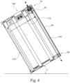
- Fig. 4 shows a schematic sectional view along the length direction of the fuel cell stack 100 of Fig. 1 .
- the cooling circuit of the fuel cell stack body 50 is schematically shown with arrows.
- the cooling circuit comprises a coolant inflow channel 110, a coolant outflow channel 120 and one or more coolant cross-flow channels 112 for cooling the individual cells.
- the one or more coolant cross-flow channels 112 connect the coolant inflow channel 110 with the coolant outflow channel 120. In Fig. 4 only two of these one or more coolant cross-flow channels 112 are shown.
- the coolant enters the cooling circuit at the coolant inflow channel 110 at the bottom device 80.
- the coolant exits the cooling circuit at the coolant outflow channel 120 at the bottom device 80.
- the fuel cell stack 100 is tilted over the short side to the left.
- the angle ⁇ can be in a wide range, preferably in the range from 0° to 60°, and more preferably in the range from 0° to 45°.
- Fig. 5 shows a further schematic sectional view along the length direction of the fuel cell stack 100 of Fig. 1 .
- the fuel cell stack 100 is tilted over the short side to the right.
- the angle ⁇ can be in a wide range, preferably in the range from 0° to 60°, and more preferably in the range from 0° to 45°.
- Fig. 6 shows a schematic sectional view along the width direction of the fuel cell stack 100 of Fig. 1 .
- the fuel cell stack 100 is tilted over the long side to the right.
- the angle ⁇ can be in a wide range, preferably in the range from 90° to 30°, and more preferably in the range from 90° to 45°.
- Fig. 7 shows a further schematic sectional view along the width direction of the fuel cell stack 100 of Fig. 1 .
- the fuel cell stack 100 is tilted over the long side to the left.
- the angle ⁇ can be in a wide range, preferably in the range from 90° to 30°, and more preferably in the range from 90° to 45°.
Landscapes
- Chemical & Material Sciences (AREA)
- Chemical Kinetics & Catalysis (AREA)
- Engineering & Computer Science (AREA)
- Life Sciences & Earth Sciences (AREA)
- Manufacturing & Machinery (AREA)
- Sustainable Development (AREA)
- Sustainable Energy (AREA)
- Electrochemistry (AREA)
- General Chemical & Material Sciences (AREA)
- Combustion & Propulsion (AREA)
- Fuel Cell (AREA)
Abstract
Description
- The present invention is related to a coolant de-gas device for de-gassing a coolant and a fuel cell stack comprising such a coolant de-gas device.
- It is known that de-gassing of a coolant is important in a cooling circuit of a fuel cell stack to ensure a high heat transfer to the coolant. In a typical fuel cell stack that requires de-airing, a separate tube has to be inserted post-assembly from the fluid port adapter side and up to the top of the coolant header to siphon off the gas bubbles and provide a de-airing chamber. Typically, a de-airing passage which is perpendicular to the stacking direction of the fuel cells and which emerges from the side of the isolator plate is used. Such a de-airing connection at the side of the isolator plate is vulnerable to mechanical damage.
- It is an object of the present invention to overcome the disadvantages described above at least partly. In particular it is an object of the present invention to provide a coolant de-gas device which limits external mechanical forces from being transferred into the isolator plate of the coolant de-gas device, and which allows a large inclination operating angle of the fuel cell stack. Furthermore, it is an object to provide a coolant de-gas device which can provide high electrical isolation.
- The aforementioned problems are solved by a coolant de-gas device with the features of claim 1 as well as a fuel cell stack with the features of claim 13. Further features and details of the invention result from the subclaims, the description and the drawings. Features and details described in connection with the coolant de-gas device according to the invention naturally also apply in connection with the fuel cell stack according to the invention, and vice versa, so that reference is or can always be made mutually with regard to the disclosure concerning the individual aspects of the invention.
- According to the present invention a coolant de-gas device for de-gassing a coolant is provided. The coolant de-gas device comprises a coolant de-gas fitting having a coolant de-gas fitting channel for de-gassing a coolant, a load plate for holding the coolant de-gas fitting, and a first isolator plate for electrical isolating against a fuel cell stack body, wherein the first isolator plate and the load plate are mechanically connected to each other, and wherein the first isolator plate comprises a first isolator plate channel for directing the coolant from a cooling circuit of the fuel cell stack body to the coolant de-gas fitting channel.
- As described the first isolator plate and the load plate are mechanically connected to each other and the load plate holds the coolant de-gas fitting. Therefore, a mechanical force applied to the coolant de-gas fitting is not directly applied to the first isolator plate. The mechanical force applied to the coolant de-gas fitting is transferred to the load plate first. Then the mechanical force is translated from the load plate to the first isolator plate. Thus, external mechanical forces are limited from being transferred into the first isolator plate on a small spot.
- If a load is applied to the coolant de-gas fitting the delicate first isolator plate is protected because the forces directly transfer to the mated load plate. One of the advantages of this invention is to not have forces translate to the first isolator plate. The load plate supports the coolant de-gas fitting mechanically while allowing the coolant de-gas fitting to be sealed against the first isolator plate and not have the first isolator plate provide mechanical support.
- Because coolant and hydrogen are flowing inside the first isolator plate, it is critical that the design of the coolant de-gas device prevents any stress cracking or damage to the first isolator plate.
- The phrase "de-gassing a coolant" means especially the gas of the coolant is de-gassed but it can also mean that not only the gas but additionally also a small part of the liquid coolant can be de-gassed. The same interpretation applies for the phrase "directing the coolant from ...".
- According to an aspect of the coolant de-gas device the first isolator plate channel has a first isolator plate channel inlet and a first isolator plate channel outlet, wherein the first isolator plate channel inlet is arranged towards the fuel cell stack body and the first isolator plate channel outlet is arranged towards the coolant de-gas fitting, wherein the first isolator plate channel is arranged in an approximate direct line from the first isolator plate channel inlet to the first isolator plate channel outlet, and wherein the first isolator plate channel outlet is connected to the coolant de-gas fitting channel.
- The first isolator plate channel is arranged in an approximate direct line. Thus, the gas bubbles of the coolant can go up even when the fuel cell stack is inclined. That is because there are no parts of the first isolator plate channel which point down even when the fuel cell stack is inclined. Therefore, the invention allows for a large inclination operating angle of a fuel cell stack, positive or negative, in any axes.
- That the first isolator plate channel outlet is connected to the coolant de-gas fitting channel means that the first isolator plate channel outlet is in fluid communication with the coolant de-gas fitting channel. The first isolator plate channel outlet can also be the coolant de-gas fitting channel inlet.
- The term "the first isolator plate channel inlet is arranged towards the fuel cell stack body" means that the first isolator plate channel inlet is on the side of the first isolator plate next to the fuel cell stack body. The term "the first isolator plate channel outlet is arranged towards the coolant de-gas fitting" means that the first isolator plate channel outlet is on the side of the first isolator plate next to the coolant de-gas fitting.
- According to a further aspect of the coolant de-gas device, the first isolator plate channel has a tapered section, wherein the cross-sectional area of the first isolator plate channel is largest at the first isolator plate channel inlet. Because of the tapered section the gas bubbles of the coolant can easily be caught. Therefore, a large inclination operating angle of a fuel cell stack is possible.
- According to a further aspect of the coolant de-gas device an axis of the coolant de-gas fitting channel is offset in parallel to an axis of the first isolator plate channel inlet. The term "offset in parallel" has the meaning that the axis of the coolant de-gas fitting channel can be shifted with respect to the axis of the first isolator plate channel inlet. That means the first isolator plate channel inlet can be shifted with respect to the coolant de-gas fitting channel where the axis of the first isolator plate channel inlet means the line perpendicular to the plane of the first isolator plate channel inlet and through a point of the opening of the first isolator plate channel inlet.
- According to a further aspect of the coolant de-gas device the coolant de-gas fitting is removable from the load plate. This has the advantage that the coolant de-gas fitting can easily be replaced.
- According to a further aspect of the coolant de-gas device the load plate has an access bore with an access bore wall, wherein the coolant de-gas fitting is arranged in the access bore. Because of the access bore the coolant can be directed through the load plate. There is no need for a channel for the coolant at the side of the load plate which can easily be damaged.
- According to a further aspect of the coolant de-gas device the coolant de-gas fitting has a protruding portion, wherein the load plate has a protruding portion protruding from the access bore wall into the access bore, wherein the protruding portion of the coolant de-gas fitting and the protruding portion of the load plate abut against each other.
- Therefore, an external mechanical force acting on the coolant de-gas fitting is transferred to the load plate. Then the force is transferred from the load plate to the first isolator plate. However, the external mechanical force is not applied to the connection between the coolant de-gas fitting and the first isolator plate. Therefore, there is no danger of the connection or the coolant de-gas fitting causing damage to the first isolator plate.
- Thus, external mechanical forces acting on the coolant de-gas fitting are limited from being transferred into the first isolator plate. The first isolator plate is therefore not prone to mechanical damage.
- The protruding portion of the coolant de-gas fitting can be a flange portion of the coolant de-gas fitting and the protruding portion of the load plate can be a flange portion of the load plate.
- According to a further aspect of the coolant de-gas device the coolant de-gas device comprises a retaining ring and a wave spring washer, wherein the access bore wall has a recess and the retaining ring is arranged in the recess, and wherein the wave spring washer is arranged between the retaining ring and the protruding portion of the coolant de-gas fitting.
- Because of this arrangement the coolant de-gas fitting is removable. The wave spring washer exerts a force on the protruding portion of the coolant de-gas fitting since the retaining ring is arranged in the recess and cannot move. Thus, the protruding portion of the coolant de-gas fitting and the protruding portion of the load plate abut against each other.
- According to a further aspect of the coolant de-gas device the coolant de-gas device comprises two O-rings, the first isolator plate has a recess with a recess wall, the coolant de-gas fitting is partly arranged in the recess, and the two O-rings are arranged between the recess wall and the coolant de-gas fitting. The double O-ring design provides a sufficiently large creepage path to ensure no appreciable loss of electrical isolation. There is only a mechanical contact between the O-rings and the first isolator plate and between the O-rings and the coolant de-gas fitting. There is no direct contact between the coolant de-gas fitting and the first isolator plate. According to a further aspect of the coolant de-gas device the coolant de-gas fitting and the first isolator plate do not directly abut against each other. This has the advantage that the coolant de-gas fitting remains centered in the first isolator plate port at all times including during thermal expansion and contraction of the first isolator plate.
- According to a further aspect of the coolant de-gas device, the coolant de-gas device comprises one or more flow control valves, wherein at least one flow control valve is arranged in the first isolator plate channel or the coolant de-gas fitting channel. Therefore, both a continuous and an intermittent flow of the coolant through the coolant de-gas device is possible.
- Further, according to the present invention a fuel cell stack is described. The fuel cell stack comprises a coolant de-gas device as described, a fuel cell stack body comprising one or more individual cells, and a bottom device comprising a second isolator plate and an end plate.
- The individual cells in the fuel cell stack body can be stacked on top of each other in a vertical direction. The individual cells can be components of fuel cells or electrolyzers based on Proton Exchange Membrane (PEM) technology, Solid Oxide Cell (SOC) technology or other competing technologies.
- The fuel cell stack body comprises a cooling circuit which is connected to the first isolator plate channel. That means the cooling circuit is in fluid communication with the first isolator plate channel. Further, the fuel cell stack body is electrically isolated because of the first isolator plate and the second isolator plate.
- According to an aspect of the fuel cell stack, the fuel cell stack comprises a cooling circuit comprising a coolant inflow channel, a coolant outflow channel and one or more coolant cross-flow channels for cooling the individual cells, wherein the one or more coolant cross-flowchannels connect the coolant inflow channel with the coolant outflow channel, and wherein the coolant inflow channel or the coolant outflow channel is connected to the first isolator plate channel.
- Because of the connection of the cooling circuit with the first isolator plate channel, a de-gassing of the coolant is possible.
- Specifically, the fuel cell stack body of the fuel cell stack comprises the cooling circuit.
- The phrase "the coolant inflow channel or the coolant outflow channel is connected to the first isolator plate channel" has the meaning that the coolant inflow channel or the coolant outflow channel is in fluid communication with the first isolator plate channel.
- According to a further aspect of the fuel cell stack, the fuel cell stack comprises Belleville springs and the coolant de-gas fitting is arranged between the Belleville springs. That means the coolant de-gas fitting can be arranged in the middle between the Belleville springs. Therefore, otherwise unused space between the Belleville springs is used to route the gaseous coolant out of the coolant de-gas device and the fuel cell stack. Further advantages, features and details of the invention will be apparent from the following description, in which embodiments of the invention are described in detail with reference to the drawings. Those drawings show:
- Figure 1
- a perspective view of a fuel cell stack,
- Figure 2
- a schematic sectional view of the coolant de-gas device shown in
Fig. 1 , - Figure 3
- a perspective view of the fuel cell stack of
Fig. 1 with a partial exploded view of the coolant de-gas device, - Figure 4
- a schematic sectional view along the length direction of the fuel cell stack of
Fig. 1 showing coolant direction flow, - Figure 5
- a further schematic sectional view along the length direction of the fuel cell stack of
Fig. 1 showing coolant direction flow, - Figure 6
- a schematic sectional view along the width direction of the fuel cell stack of
Fig. 1 showing coolant direction flow, and - Figure 7
- a further schematic sectional view along the width direction of the fuel cell stack of
Fig. 1 showing coolant direction flow. -
Fig. 1 shows a perspective view of afuel cell stack 100. Among other components, thefuel cell stack 100 comprises acoolant de-gas device 10 and a fuelcell stack body 50. The fuelcell stack body 50 has one or more individual cells. Further, afirst isolator plate 40 and aload plate 30 can be seen inFig. 1 . -
Fig. 2 shows a schematic sectional view of thecoolant de-gas device 10 shown inFig. 1 . The coolant de-gasdevice 10 comprises a coolant de-gas fitting 20, theload plate 30 and thefirst isolator plate 40. The coolant de-gas fitting 20 has a coolant de-gas fittingchannel 22 for de-gassing the coolant. Theload plate 30 is used for holding the coolant de-gas fitting 20. Further, thefirst isolator plate 40 is used for electrically isolating the fuelcell stack body 50 fromload plate 30. Thefirst isolator plate 40 and theload plate 30 are mechanically connected to each other. As can be seen inFig. 2 , thefirst isolator plate 40 comprises a firstisolator plate channel 42, wherein the firstisolator plate channel 42 is used for directing the coolant from a cooling circuit of the fuelcell stack body 50 to the coolantde-gas fitting channel 22. Therefore, the firstisolator plate channel 42 can lead the coolant from the fuelcell stack body 50 to the coolantde-gas fitting channel 22. - Because the
load plate 30 holds the coolant de-gas fitting 20 and further theload plate 30 and thefirst isolator plate 40 are mechanically connected to each other, a force acting on the coolant de-gas fitting 20 is not directly passed onto thefirst isolator plate 40. Therefore, any external mechanical loads applied to the coolant de-gas fitting 20 do not directly transfer to the fragilefirst isolator plate 40. As can be seen inFig. 2 , the firstisolator plate channel 42 has a first isolatorplate channel inlet 44 and a first isolatorplate channel outlet 46. The first isolatorplate channel inlet 44 is arranged on the side of thefirst isolator plate 40 which is next to the fuelcell stack body 50 and the first isolatorplate channel outlet 46 is arranged on the side of thefirst isolator plate 40 which is next to the coolant de-gas fitting 20. Further, the firstisolator plate channel 42 can be arranged in a direct line from the first isolatorplate channel inlet 44 to the first isolatorplate channel outlet 46. The first isolatorplate channel outlet 46 is in fluid communication to the coolantde-gas fitting channel 22. This allows the coolant to flow through the first isolatorplate channel outlet 46 into the coolantde-gas fitting channel 22. - The arrangement of the first
isolator plate channel 42 in a direct line leads to a channel which has no parts that trap gas within the coolant even when thefuel cell stack 100 is inclined. Therefore, the gas bubbles of the coolant can always go up to the coolantde-gas fitting channel 22. - The first
isolator plate channel 42 can have a taperedsection 48. Thus, the cross-sectional area of the firstisolator plate channel 42 is largest at the first isolatorplate channel inlet 44. Therefore, gas bubbles of the coolant can easily flow into the firstisolator plate channel 42 even when thefuel cell stack 100 is inclined. - As can be seen in
Fig. 2 , the first isolatorplate channel outlet 46 is not above the first isolatorplate channel inlet 44. There is an offset between the first isolatorplate channel outlet 46 and the first isolatorplate channel inlet 44. - The
load plate 30 has an access bore 32 and the coolant de-gas fitting 20 is arranged in the access bore 32. Furthermore, the coolant de-gas fitting 20 has a protrudingportion 24. Also theload plate 30 has a protrudingportion 34 protruding from anaccess bore wall 36 into the access bore 32. As can be seen inFig. 2 , the protrudingportion 24 of the coolant de-gas fitting 20 and the protrudingportion 34 of theload plate 30 contact each other. - Furthermore, the
coolant de-gas device 10 can comprise a retainingring 26 and awave spring washer 28. The access borewall 36 can have arecess 38 and the retainingring 26 can be arranged in therecess 38. That means thewave spring washer 28 can be arranged between the retainingring 26 and the protrudingportion 24 of the coolant de-gas fitting 20. - Since the retaining
ring 26 and thewave spring washer 28 are removable ,the coolant de-gas fitting 20 is also removable from theload plate 30. - A force acting on the coolant de-gas fitting 20 can be transferred to the
load plate 30 via the protrudingportion 24 of the coolant de-gas fitting 20 and the protrudingportion 34 of theload plate 30. - As can be seen in
Fig. 2 , thecoolant de-gas device 10 of thefuel cell stack 100 comprises Belleville springs 12 and the coolant de-gas fitting 20 is arranged between the Belleville springs 12. That means otherwise unused space between the Belleville springs 12 is used for the de-gassing of the coolant. - As can be seen in
Fig. 2 , thecoolant de-gas device 10 comprises a first O-ring 16 and a second O-ring 14. Thefirst isolator plate 40 has a recess 90 with a recess wall 92, wherein the coolant de-gas fitting 20 can be partly inserted in the recess 90. Both O-rings rings first isolator plate 40 do not directly abut against each other. Thus, the two O-rings - Optionally, the
coolant de-gas device 10 can comprise aflow control valve 18. As can be seen inFig. 2 , theflow control valve 18 is arranged in the firstisolator plate channel 42. Alternatively, theflow control valve 18 can be arranged in the coolantde-gas fitting channel 22.Fig. 3 shows a perspective view of thefuel cell stack 100 ofFig. 1 with a partial exploded view of thecoolant de-gas device 10.Fig. 3 shows the fuelcell stack body 50, theload plate 30 and thefirst isolator plate 40. Thefuel cell stack 100 also comprises abottom device 80. Thebottom device 80 comprises asecond isolator plate 60 and anend plate 70. The fuelcell stack body 50 is arranged between the twoisolator plates - The retaining
ring 26, thewave spring washer 28, the coolant de-gas fitting 20, the first O-ring 16 and the second O-ring 14 of thecoolant de-gas device 10 are shown in an exploded view. -
Fig. 4 shows a schematic sectional view along the length direction of thefuel cell stack 100 ofFig. 1 . The cooling circuit of the fuelcell stack body 50 is schematically shown with arrows. The cooling circuit comprises acoolant inflow channel 110, acoolant outflow channel 120 and one or morecoolant cross-flow channels 112 for cooling the individual cells. The one or morecoolant cross-flow channels 112 connect thecoolant inflow channel 110 with thecoolant outflow channel 120. InFig. 4 only two of these one or morecoolant cross-flow channels 112 are shown. The coolant enters the cooling circuit at thecoolant inflow channel 110 at thebottom device 80. The coolant exits the cooling circuit at thecoolant outflow channel 120 at thebottom device 80. The gas bubbles entrained in the coolant exit the cooling circuit with the coolant outflow at thecoolant outflow channel 120 next to thecoolant de-gas device 10. That is because thecoolant outflow channel 120 is connected to the firstisolator plate channel 42. Additionally, thecoolant inflow channel 110 can be connected to the firstisolator plate channel 42. - Because of the before described arrangement of the
coolant de-gas device 10 it is possible to operate thefuel cell stack 100 at an inclined angle α. InFig. 4 thefuel cell stack 100 is tilted over the short side to the left. The angle α can be in a wide range, preferably in the range from 0° to 60°, and more preferably in the range from 0° to 45°. -
Fig. 5 shows a further schematic sectional view along the length direction of thefuel cell stack 100 ofFig. 1 . InFig. 5 thefuel cell stack 100 is tilted over the short side to the right. The angle α can be in a wide range, preferably in the range from 0° to 60°, and more preferably in the range from 0° to 45°. -
Fig. 6 shows a schematic sectional view along the width direction of thefuel cell stack 100 ofFig. 1 . InFig. 6 thefuel cell stack 100 is tilted over the long side to the right. The angle α can be in a wide range, preferably in the range from 90° to 30°, and more preferably in the range from 90° to 45°. -
Fig. 7 shows a further schematic sectional view along the width direction of thefuel cell stack 100 ofFig. 1 . InFig. 7 thefuel cell stack 100 is tilted over the long side to the left. The angle α can be in a wide range, preferably in the range from 90° to 30°, and more preferably in the range from 90° to 45°. - The above description of the drawings describes the present invention by way of example only.
-
- 10
- coolant de-gas device
- 12
- Belleville springs
- 14
- second O-ring
- 16
- first O-ring
- 18
- flow control valve
- 20
- coolant de-gas fitting
- 22
- coolant de-gas fitting channel
- 24
- protruding portion of the coolant de-gas fitting
- 26
- retaining ring
- 28
- wave spring washer
- 30
- load plate
- 32
- access bore
- 34
- protruding portion of the load plate
- 36
- access bore wall
- 38
- recess of the access bore wall
- 40
- first isolator plate
- 42
- first isolator plate channel
- 44
- first isolator plate channel inlet
- 46
- first isolator plate channel outlet and coolant de-gas channel inlet
- 48
- tapered section of the first isolator plate channel
- 50
- fuel cell stack body
- 60
- second isolator plate
- 70
- end plate
- 80
- bottom device
- 90
- recess of the first isolator plate
- 92
- recess wall of the first isolator plate
- 100
- fuel cell stack
- 110
- coolant inflow channel
- 112
- coolant cross-flow channel
- 120
- coolant outflow channel
Claims (14)
- Coolant de-gas device (10) for de-gassing a coolant characterized bya coolant de-gas fitting (20) having a coolant de-gas fitting channel (22) for de-gassing a coolant,a load plate (30) for holding the coolant de-gas fitting (20), anda first isolator plate (40) for electrical isolating against a fuel cell stack body (50), wherein the first isolator plate (40) and the load plate (30) are mechanically connected to each other, and wherein the first isolator plate (40) comprises a first isolator plate channel (42) for directing the coolant from a cooling circuit of the fuel cell stack body (50) to the coolant de-gas fitting channel (22).
- Coolant de-gas device (10) according to claim 1, characterized in that the first isolator plate channel (42) has a first isolator plate channel inlet (44) and a first isolator plate channel outlet (46), wherein the first isolator plate channel inlet (44) is arranged towards the fuel cell stack body (50) and the first isolator plate channel outlet (46) is arranged towards the coolant de-gas fitting (20), wherein the first isolator plate channel (42) is arranged in a direct line from the first isolator plate channel inlet (44) to the first isolator plate channel outlet (46), and wherein the first isolator plate channel outlet (46) is connected to the coolant de-gas fitting channel (22).
- Coolant de-gas device (10) according to claim 1 or 2, characterized in that the first isolator plate channel (42) has a tapered section (48), wherein the cross-sectional area of the first isolator plate channel (42) is largest at the first isolator plate channel inlet (44).
- Coolant de-gas device (10) according to claim 2 or 3, characterized in that an axis of the coolant de-gas fitting channel (22) is offset in parallel to an axis of the first isolator plate channel inlet (44).
- Coolant de-gas device (10) according to any of the preceding claims, characterized in that the coolant de-gas fitting (20) is removable from the load plate (30).
- Coolant de-gas device (10) according to any of the preceding claims, characterized in that the load plate (30) has an access bore (32) with an access bore wall (36), wherein the coolant de-gas fitting (20) is arranged in the access bore (32).
- Coolant de-gas device (10) according to claim 6, characterized in that the coolant de-gas fitting (20) has a protruding portion (24), wherein the load plate (30) has a protruding portion (34) protruding from the access bore wall (36) into the access bore (32), wherein the protruding portion (24) of the coolant de-gas fitting (20) and the protruding portion (34) of the load plate (30) abut against each other.
- Coolant de-gas device (10) according to claim 6 or 7, characterized in that the coolant de-gas device (10) comprises a retaining ring (26) and a wave spring washer (28), wherein the access bore wall (36) has a recess (38) and the retaining ring (26) is arranged in the recess (38), and wherein the wave spring washer (28) is arranged between the retaining ring (26) and the protruding portion (24) of the coolant de-gas fitting (20).
- Coolant de-gas device (10) according to any of the preceding claims, characterized in that the coolant de-gas device (10) comprises two O-rings (14, 16), the first isolator plate (40) has a recess (90) with a recess wall (92), the coolant de-gas fitting (20) is partly arranged in the recess (90), and the two O-rings (14, 16) are arranged between the recess wall (92) and the coolant de-gas fitting (20).
- Coolant de-gas device (10) according to any of the preceding claims, characterized in that the coolant de-gas fitting (20) and the first isolator plate (40) do not directly abut against each other.
- Coolant de-gas device (10) according to any of the preceding claims, characterized in that the coolant de-gas device (10) comprises one or more flow control valves (18), wherein at least one flow control valve (18) is arranged in the first isolator plate channel (42) or the coolant de-gas fitting channel (22).
- Fuel cell stack (100), characterized bya coolant de-gas device (10) according to any of the preceding claims,a fuel cell stack body (50) comprising one or more individual cells, anda bottom device (80) comprising a second isolator plate (60) and an end plate (70).
- Fuel cell stack (100) according to claim 12, characterized in that the fuel cell stack (100) comprises a cooling circuit comprising a coolant inflow channel (110), a coolant outflow channel (120) and one or more coolant cross-flow channels (112) for cooling the individual cells, wherein the one or more coolant cross-flow channels (112) connect the coolant inflow channel (110) with the coolant outflow channel (120), and wherein the coolant inflow channel (110) or the coolant outflow channel (120) is connected to the first isolator plate channel (42).
- Fuel cell stack (100) according to claims 12 and 13, characterized in that the fuel cell stack (100) comprises Belleville springs (12) and the coolant de-gas fitting (20) is arranged between the Belleville springs (12).
Priority Applications (3)
| Application Number | Priority Date | Filing Date | Title |
|---|---|---|---|
| EP23217831.9A EP4576282A1 (en) | 2023-12-19 | 2023-12-19 | Coolant de-gas device and fuel cell stack |
| CN202411879358.6A CN120184282A (en) | 2023-12-19 | 2024-12-19 | Coolant degassing device and fuel cell stack |
| KR1020240190837A KR20250095556A (en) | 2023-12-19 | 2024-12-19 | Coolant de-gas device and fuel cell stack |
Applications Claiming Priority (1)
| Application Number | Priority Date | Filing Date | Title |
|---|---|---|---|
| EP23217831.9A EP4576282A1 (en) | 2023-12-19 | 2023-12-19 | Coolant de-gas device and fuel cell stack |
Publications (1)
| Publication Number | Publication Date |
|---|---|
| EP4576282A1 true EP4576282A1 (en) | 2025-06-25 |
Family
ID=89378642
Family Applications (1)
| Application Number | Title | Priority Date | Filing Date |
|---|---|---|---|
| EP23217831.9A Pending EP4576282A1 (en) | 2023-12-19 | 2023-12-19 | Coolant de-gas device and fuel cell stack |
Country Status (3)
| Country | Link |
|---|---|
| EP (1) | EP4576282A1 (en) |
| KR (1) | KR20250095556A (en) |
| CN (1) | CN120184282A (en) |
Citations (2)
| Publication number | Priority date | Publication date | Assignee | Title |
|---|---|---|---|---|
| KR100862590B1 (en) * | 2007-04-26 | 2008-10-09 | 한국기계연구원 | Direct methanol fuel cell |
| US20110143248A1 (en) * | 2009-12-16 | 2011-06-16 | Toyota Jidosha Kabushiki Kaisha | Fuel cell |
-
2023
- 2023-12-19 EP EP23217831.9A patent/EP4576282A1/en active Pending
-
2024
- 2024-12-19 KR KR1020240190837A patent/KR20250095556A/en active Pending
- 2024-12-19 CN CN202411879358.6A patent/CN120184282A/en active Pending
Patent Citations (2)
| Publication number | Priority date | Publication date | Assignee | Title |
|---|---|---|---|---|
| KR100862590B1 (en) * | 2007-04-26 | 2008-10-09 | 한국기계연구원 | Direct methanol fuel cell |
| US20110143248A1 (en) * | 2009-12-16 | 2011-06-16 | Toyota Jidosha Kabushiki Kaisha | Fuel cell |
Also Published As
| Publication number | Publication date |
|---|---|
| KR20250095556A (en) | 2025-06-26 |
| CN120184282A (en) | 2025-06-20 |
Similar Documents
| Publication | Publication Date | Title |
|---|---|---|
| JP5322950B2 (en) | Medium supply plate for fuel cell stack | |
| US6844100B2 (en) | Fuel cell stack and fuel cell module | |
| US7771884B2 (en) | Solid oxide fuel cell stack having an integral gas distribution manifold | |
| AU2007298869B2 (en) | Solid oxide fuel cell comprising a thermal exchanger | |
| ES2430320T3 (en) | Compact solid oxide fuel cell device | |
| EP4220828B1 (en) | Battery pack | |
| US11469436B2 (en) | Fuel cell device | |
| US11271240B2 (en) | Fuel cell column containing electrically insulated fuel manifold and manifold jumper | |
| US9401524B2 (en) | Compliant stack for a planar solid oxide fuel cell | |
| US20020009648A1 (en) | Liquid-cooled fuel cell battery and method for operating it | |
| CN101553947A (en) | Compact fuel cell stack with multi-plate arrangement | |
| CA2710670C (en) | Fuel cell system | |
| KR20070091310A (en) | Fuel cell stack assembly | |
| US6316137B1 (en) | Cooling a fuel cell stack | |
| CN118448768A (en) | Cell cooling unit, cooling module and battery module for a motor vehicle | |
| JP2006253134A (en) | System and method for minimizing temperature differences and temperature gradients in fuel cells | |
| CN118974985A (en) | Sealing device for at least one fuel cell stack | |
| KR20170132286A (en) | Fuel-cell power generation unit and fuel-cell stack | |
| KR20250095556A (en) | Coolant de-gas device and fuel cell stack | |
| EP1947726A1 (en) | Fuel cell manifold | |
| US11374237B2 (en) | Fuel cell stack | |
| JP2002343409A (en) | Fuel cell manifold | |
| US11916265B2 (en) | Metal-dielectric conduit assemblies and methods of making thereof | |
| EP4621892A1 (en) | A stack assembly with a load applying mechanism | |
| US7807309B2 (en) | Integrated coolant header venting for a fuel cell stack |
Legal Events
| Date | Code | Title | Description |
|---|---|---|---|
| PUAI | Public reference made under article 153(3) epc to a published international application that has entered the european phase |
Free format text: ORIGINAL CODE: 0009012 |
|
| STAA | Information on the status of an ep patent application or granted ep patent |
Free format text: STATUS: THE APPLICATION HAS BEEN PUBLISHED |
|
| AK | Designated contracting states |
Kind code of ref document: A1 Designated state(s): AL AT BE BG CH CY CZ DE DK EE ES FI FR GB GR HR HU IE IS IT LI LT LU LV MC ME MK MT NL NO PL PT RO RS SE SI SK SM TR |
|
| P01 | Opt-out of the competence of the unified patent court (upc) registered |
Free format text: CASE NUMBER: UPC_APP_3285_4576282/2025 Effective date: 20250813 |
|
| STAA | Information on the status of an ep patent application or granted ep patent |
Free format text: STATUS: REQUEST FOR EXAMINATION WAS MADE |
|
| 17P | Request for examination filed |
Effective date: 20251119 |