EP4576240A1 - Electrochemical apparatus, manufacturing method therefor, and electronic apparatus - Google Patents
Electrochemical apparatus, manufacturing method therefor, and electronic apparatus Download PDFInfo
- Publication number
- EP4576240A1 EP4576240A1 EP22959141.7A EP22959141A EP4576240A1 EP 4576240 A1 EP4576240 A1 EP 4576240A1 EP 22959141 A EP22959141 A EP 22959141A EP 4576240 A1 EP4576240 A1 EP 4576240A1
- Authority
- EP
- European Patent Office
- Prior art keywords
- positive electrode
- active material
- current collector
- electrode active
- negative electrode
- Prior art date
- Legal status (The legal status is an assumption and is not a legal conclusion. Google has not performed a legal analysis and makes no representation as to the accuracy of the status listed.)
- Pending
Links
Images


Classifications
-
- H—ELECTRICITY
- H01—ELECTRIC ELEMENTS
- H01M—PROCESSES OR MEANS, e.g. BATTERIES, FOR THE DIRECT CONVERSION OF CHEMICAL ENERGY INTO ELECTRICAL ENERGY
- H01M10/00—Secondary cells; Manufacture thereof
- H01M10/05—Accumulators with non-aqueous electrolyte
- H01M10/052—Li-accumulators
- H01M10/0525—Rocking-chair batteries, i.e. batteries with lithium insertion or intercalation in both electrodes; Lithium-ion batteries
-
- H—ELECTRICITY
- H01—ELECTRIC ELEMENTS
- H01M—PROCESSES OR MEANS, e.g. BATTERIES, FOR THE DIRECT CONVERSION OF CHEMICAL ENERGY INTO ELECTRICAL ENERGY
- H01M10/00—Secondary cells; Manufacture thereof
- H01M10/05—Accumulators with non-aqueous electrolyte
- H01M10/058—Construction or manufacture
- H01M10/0587—Construction or manufacture of accumulators having only wound construction elements, i.e. wound positive electrodes, wound negative electrodes and wound separators
-
- H—ELECTRICITY
- H01—ELECTRIC ELEMENTS
- H01M—PROCESSES OR MEANS, e.g. BATTERIES, FOR THE DIRECT CONVERSION OF CHEMICAL ENERGY INTO ELECTRICAL ENERGY
- H01M4/00—Electrodes
- H01M4/02—Electrodes composed of, or comprising, active material
- H01M4/13—Electrodes for accumulators with non-aqueous electrolyte, e.g. for lithium-accumulators; Processes of manufacture thereof
- H01M4/131—Electrodes based on mixed oxides or hydroxides, or on mixtures of oxides or hydroxides, e.g. LiCoOx
-
- H—ELECTRICITY
- H01—ELECTRIC ELEMENTS
- H01M—PROCESSES OR MEANS, e.g. BATTERIES, FOR THE DIRECT CONVERSION OF CHEMICAL ENERGY INTO ELECTRICAL ENERGY
- H01M4/00—Electrodes
- H01M4/02—Electrodes composed of, or comprising, active material
- H01M4/13—Electrodes for accumulators with non-aqueous electrolyte, e.g. for lithium-accumulators; Processes of manufacture thereof
- H01M4/133—Electrodes based on carbonaceous material, e.g. graphite-intercalation compounds or CFx
-
- H—ELECTRICITY
- H01—ELECTRIC ELEMENTS
- H01M—PROCESSES OR MEANS, e.g. BATTERIES, FOR THE DIRECT CONVERSION OF CHEMICAL ENERGY INTO ELECTRICAL ENERGY
- H01M4/00—Electrodes
- H01M4/02—Electrodes composed of, or comprising, active material
- H01M4/13—Electrodes for accumulators with non-aqueous electrolyte, e.g. for lithium-accumulators; Processes of manufacture thereof
- H01M4/136—Electrodes based on inorganic compounds other than oxides or hydroxides, e.g. sulfides, selenides, tellurides, halogenides or LiCoFy
-
- H—ELECTRICITY
- H01—ELECTRIC ELEMENTS
- H01M—PROCESSES OR MEANS, e.g. BATTERIES, FOR THE DIRECT CONVERSION OF CHEMICAL ENERGY INTO ELECTRICAL ENERGY
- H01M4/00—Electrodes
- H01M4/02—Electrodes composed of, or comprising, active material
- H01M4/36—Selection of substances as active materials, active masses, active liquids
- H01M4/48—Selection of substances as active materials, active masses, active liquids of inorganic oxides or hydroxides
- H01M4/50—Selection of substances as active materials, active masses, active liquids of inorganic oxides or hydroxides of manganese
- H01M4/505—Selection of substances as active materials, active masses, active liquids of inorganic oxides or hydroxides of manganese of mixed oxides or hydroxides containing manganese for inserting or intercalating light metals, e.g. LiMn2O4 or LiMn2OxFy
-
- H—ELECTRICITY
- H01—ELECTRIC ELEMENTS
- H01M—PROCESSES OR MEANS, e.g. BATTERIES, FOR THE DIRECT CONVERSION OF CHEMICAL ENERGY INTO ELECTRICAL ENERGY
- H01M4/00—Electrodes
- H01M4/02—Electrodes composed of, or comprising, active material
- H01M4/36—Selection of substances as active materials, active masses, active liquids
- H01M4/48—Selection of substances as active materials, active masses, active liquids of inorganic oxides or hydroxides
- H01M4/52—Selection of substances as active materials, active masses, active liquids of inorganic oxides or hydroxides of nickel, cobalt or iron
- H01M4/525—Selection of substances as active materials, active masses, active liquids of inorganic oxides or hydroxides of nickel, cobalt or iron of mixed oxides or hydroxides containing iron, cobalt or nickel for inserting or intercalating light metals, e.g. LiNiO2, LiCoO2 or LiCoOxFy
-
- H—ELECTRICITY
- H01—ELECTRIC ELEMENTS
- H01M—PROCESSES OR MEANS, e.g. BATTERIES, FOR THE DIRECT CONVERSION OF CHEMICAL ENERGY INTO ELECTRICAL ENERGY
- H01M4/00—Electrodes
- H01M4/02—Electrodes composed of, or comprising, active material
- H01M4/36—Selection of substances as active materials, active masses, active liquids
- H01M4/58—Selection of substances as active materials, active masses, active liquids of inorganic compounds other than oxides or hydroxides, e.g. sulfides, selenides, tellurides, halogenides or LiCoFy; of polyanionic structures, e.g. phosphates, silicates or borates
- H01M4/5825—Oxygenated metallic salts or polyanionic structures, e.g. borates, phosphates, silicates, olivines
-
- H—ELECTRICITY
- H01—ELECTRIC ELEMENTS
- H01M—PROCESSES OR MEANS, e.g. BATTERIES, FOR THE DIRECT CONVERSION OF CHEMICAL ENERGY INTO ELECTRICAL ENERGY
- H01M4/00—Electrodes
- H01M4/02—Electrodes composed of, or comprising, active material
- H01M4/36—Selection of substances as active materials, active masses, active liquids
- H01M4/58—Selection of substances as active materials, active masses, active liquids of inorganic compounds other than oxides or hydroxides, e.g. sulfides, selenides, tellurides, halogenides or LiCoFy; of polyanionic structures, e.g. phosphates, silicates or borates
- H01M4/583—Carbonaceous material, e.g. graphite-intercalation compounds or CFx
- H01M4/587—Carbonaceous material, e.g. graphite-intercalation compounds or CFx for inserting or intercalating light metals
-
- H—ELECTRICITY
- H01—ELECTRIC ELEMENTS
- H01M—PROCESSES OR MEANS, e.g. BATTERIES, FOR THE DIRECT CONVERSION OF CHEMICAL ENERGY INTO ELECTRICAL ENERGY
- H01M4/00—Electrodes
- H01M4/02—Electrodes composed of, or comprising, active material
- H01M4/62—Selection of inactive substances as ingredients for active masses, e.g. binders, fillers
-
- H—ELECTRICITY
- H01—ELECTRIC ELEMENTS
- H01M—PROCESSES OR MEANS, e.g. BATTERIES, FOR THE DIRECT CONVERSION OF CHEMICAL ENERGY INTO ELECTRICAL ENERGY
- H01M50/00—Constructional details or processes of manufacture of the non-active parts of electrochemical cells other than fuel cells, e.g. hybrid cells
- H01M50/50—Current conducting connections for cells or batteries
- H01M50/528—Fixed electrical connections, i.e. not intended for disconnection
-
- H—ELECTRICITY
- H01—ELECTRIC ELEMENTS
- H01M—PROCESSES OR MEANS, e.g. BATTERIES, FOR THE DIRECT CONVERSION OF CHEMICAL ENERGY INTO ELECTRICAL ENERGY
- H01M50/00—Constructional details or processes of manufacture of the non-active parts of electrochemical cells other than fuel cells, e.g. hybrid cells
- H01M50/50—Current conducting connections for cells or batteries
- H01M50/531—Electrode connections inside a battery casing
- H01M50/533—Electrode connections inside a battery casing characterised by the shape of the leads or tabs
-
- H—ELECTRICITY
- H01—ELECTRIC ELEMENTS
- H01M—PROCESSES OR MEANS, e.g. BATTERIES, FOR THE DIRECT CONVERSION OF CHEMICAL ENERGY INTO ELECTRICAL ENERGY
- H01M50/00—Constructional details or processes of manufacture of the non-active parts of electrochemical cells other than fuel cells, e.g. hybrid cells
- H01M50/50—Current conducting connections for cells or batteries
- H01M50/531—Electrode connections inside a battery casing
- H01M50/536—Electrode connections inside a battery casing characterised by the method of fixing the leads to the electrodes, e.g. by welding
-
- H—ELECTRICITY
- H01—ELECTRIC ELEMENTS
- H01M—PROCESSES OR MEANS, e.g. BATTERIES, FOR THE DIRECT CONVERSION OF CHEMICAL ENERGY INTO ELECTRICAL ENERGY
- H01M4/00—Electrodes
- H01M4/02—Electrodes composed of, or comprising, active material
- H01M2004/021—Physical characteristics, e.g. porosity, surface area
-
- H—ELECTRICITY
- H01—ELECTRIC ELEMENTS
- H01M—PROCESSES OR MEANS, e.g. BATTERIES, FOR THE DIRECT CONVERSION OF CHEMICAL ENERGY INTO ELECTRICAL ENERGY
- H01M4/00—Electrodes
- H01M4/02—Electrodes composed of, or comprising, active material
- H01M4/62—Selection of inactive substances as ingredients for active masses, e.g. binders, fillers
- H01M4/621—Binders
- H01M4/622—Binders being polymers
- H01M4/623—Binders being polymers fluorinated polymers
-
- H—ELECTRICITY
- H01—ELECTRIC ELEMENTS
- H01M—PROCESSES OR MEANS, e.g. BATTERIES, FOR THE DIRECT CONVERSION OF CHEMICAL ENERGY INTO ELECTRICAL ENERGY
- H01M4/00—Electrodes
- H01M4/02—Electrodes composed of, or comprising, active material
- H01M4/62—Selection of inactive substances as ingredients for active masses, e.g. binders, fillers
- H01M4/624—Electric conductive fillers
- H01M4/625—Carbon or graphite
-
- Y—GENERAL TAGGING OF NEW TECHNOLOGICAL DEVELOPMENTS; GENERAL TAGGING OF CROSS-SECTIONAL TECHNOLOGIES SPANNING OVER SEVERAL SECTIONS OF THE IPC; TECHNICAL SUBJECTS COVERED BY FORMER USPC CROSS-REFERENCE ART COLLECTIONS [XRACs] AND DIGESTS
- Y02—TECHNOLOGIES OR APPLICATIONS FOR MITIGATION OR ADAPTATION AGAINST CLIMATE CHANGE
- Y02E—REDUCTION OF GREENHOUSE GAS [GHG] EMISSIONS, RELATED TO ENERGY GENERATION, TRANSMISSION OR DISTRIBUTION
- Y02E60/00—Enabling technologies; Technologies with a potential or indirect contribution to GHG emissions mitigation
- Y02E60/10—Energy storage using batteries
Definitions
- Lithium-ion batteries electrochemical apparatus
- characteristics such as high operating voltage, high energy density, long cycle life, and wide operating temperature range. These excellent characteristics have enabled lithium-ion batteries to be widely used in the three major fields of consumer electronics, power batteries, and energy storage.
- the purpose of this application is to provide an electrochemical apparatus, a preparation method thereof, and an electronic apparatus to improve the energy density and safety performance of the electrochemical apparatus.
- Specific technical solutions are as follows:
- an electrochemical apparatus including an electrode assembly, where the electrode assembly includes a positive electrode plate.
- the positive electrode plate includes a positive electrode current collector and a first positive electrode active material layer disposed on a first surface of the positive electrode current collector and a second positive electrode active material layer disposed on a second surface of the positive electrode current collector, the first surface and the second surface are two opposite surfaces of the positive electrode current collector, and the first positive electrode active material layer is provided with a first groove exposing the first surface.
- the electrochemical apparatus is provided with the first groove exposing the first surface on the first positive electrode active material layer, the positive electrode connection portion is at least partially located within the first groove and welded to the first surface, forming a single-sided groove embedded tab structure, and the second surface is provided with the second positive electrode active material layer, achieving the retention of an uncoated foil zone on only one side of the positive electrode plate, unlike an existing positive electrode plate with an embedded tab structure that requires the retention of an uncoated foil zone on each of two sides, thereby enhancing the energy density of the electrochemical apparatus. Additionally, this can alleviate the problem of poor interface between the positive electrode and the negative electrode at the position where the tab is provided, reducing the risk of lithium precipitation.
- the positive electrode connection portion is welded to the first surface through laser welding.
- Laser welding requires energy to be applied only to one side of the positive electrode current collector to melt the welding position, making it more suitable for the electrode plate structure of this application.
- the aging problem of the existing embedded tab structure positive electrode plate can be improved, thereby enhancing the safety of the electrochemical apparatus.
- the positive electrode connection portion and the first surface are welded to form a welding portion, wherein the welding portion penetrates through the positive electrode tab and at least partially penetrates the positive electrode current collector.
- D v 50 of the second positive electrode active material is B ⁇ m
- welding strength between the positive electrode connection portion and the positive electrode current collector is A N/m
- a thickness of the positive electrode current collector is T ⁇ m
- tensile strength of the positive electrode current collector is S MPa, wherein B/T ⁇ A ⁇ S.
- a thermal conductivity of the positive electrode current collector ranges from 30 W ⁇ m -1 ⁇ K -1 to 400 W ⁇ m -1 ⁇ K -1 , preferably 200 W ⁇ m -1 ⁇ K -1 to 250 W ⁇ m -1 ⁇ K -1 ; and a thermal conductivity of the positive electrode tab ranges from 30 W ⁇ m -1 ⁇ K -1 to 400 W ⁇ m -1 ⁇ K -1 , preferably 200 W ⁇ m -1 ⁇ K -1 to 250 W. m -1 ⁇ K -1 .
- the selection of the positive electrode current collector and positive electrode tab with thermal conductivities within the above ranges helps to improve the heat dissipation performance of the positive electrode plate, thereby mitigating the aging problem of the positive electrode plate caused by heat accumulation during the use of the electrochemical apparatus, and further enhancing the safety performance of the electrochemical apparatus.
- the electrode assembly further includes a negative electrode plate and a separator disposed between the positive electrode plate and the negative electrode plate, the positive electrode plate, the separator, and the negative electrode plate are stacked together, and the second positive electrode active material layer on the second surface corresponding to the first groove is in contact with the separator.
- a negative electrode plate and a separator disposed between the positive electrode plate and the negative electrode plate, the positive electrode plate, the separator, and the negative electrode plate are stacked together, and the second positive electrode active material layer on the second surface corresponding to the first groove is in contact with the separator.
- the negative electrode plate includes a negative electrode current collector and negative electrode active material layers disposed on two surfaces of the negative electrode current collector, the negative electrode active material layers on the two surfaces of the negative electrode current collector each are provided with a second groove exposing the surface of the negative electrode current collector, and the second groove on one side of the negative electrode current collector is opposite the second groove on another side of the negative electrode current collector.
- the negative electrode plate further includes a negative electrode tab, wherein the negative electrode tab includes a negative electrode connection portion, and the negative electrode connection portion is at least partially located within the second groove and welded to the negative electrode current collector, the welding including ultrasonic welding or resistance welding.
- the configuration of such a structure can improve the welding strength of the negative electrode tab, reducing the risk of failure due to dropping.
- the negative electrode active material layer of this application includes graphite, which helps to mitigate the problem of change in material structure of the negative electrode active material layer due to the impact of laser welding heat, thereby reducing the risk of lithium precipitation.
- the first positive electrode active material layer includes a first positive electrode active material, a first binder, and a first conductive agent
- the second positive electrode active material layer further includes a second binder and a second conductive agent
- the first positive electrode active material or the second positive electrode active material includes at least one of lithium cobalt oxide, lithium nickel cobalt manganese oxide, lithium nickel cobalt aluminum oxide, lithium manganese oxide, lithium iron phosphate, lithium iron manganese phosphate, or lithium-rich manganese-based oxide.
- the first binder or the second binder includes at least one of polyvinylidene fluoride, a vinylidene fluoride-fluorinated olefin copolymer, polyvinyl pyrrolidone, polyacrylonitrile, polymethyl acrylate, polytetrafluoroethylene, sodium carboxymethyl cellulose, styrene-butadiene rubber, polyurethane, fluorinated rubber, or polyvinyl alcohol.
- the first conductive agent or the second conductive agent includes at least one of conductive carbon black, carbon nanotubes, conductive graphite, graphene, or carbon nanofibers. The selection of the above conductive agent helps to improve the conductivity of the positive electrode plate.
- the second positive electrode active material layer includes a first layer and a second layer stacked together, the first layer is located between the positive electrode current collector and the second layer, the second layer includes the second positive electrode active material, and the first layer includes a ceramic material, a third binder, and a third conductive agent;
- the ceramic material includes at least one of hafnium dioxide, strontium titanate, tin dioxide, cesium oxide, magnesium oxide, nickel oxide, calcium oxide, barium oxide, zinc oxide, zirconium oxide, yttrium oxide, aluminum oxide, titanium oxide, silicon dioxide, boehmite, magnesium hydroxide, or aluminum hydroxide.
- Selection of the above ceramic materials can improve the heat-resistance performance of the first positive electrode active material or the second positive electrode active material, reducing the impact of welding. Additionally, when the above ceramic materials are selected, a resistance layer with high resistance is adhered on a surface of the positive electrode current collector, reducing the risk of an internal short circuit caused by direct contact between the positive electrode current collector and the negative electrode active material layer, which could lead to combustion or explosion, thereby enhancing the safety performance of the electrochemical apparatus.
- the third binder includes at least one of polyvinylidene fluoride, a vinylidene fluoride-fluorinated olefin copolymer, polyvinyl pyrrolidone, polyacrylonitrile, polymethyl acrylate, polytetrafluoroethylene, sodium carboxymethyl cellulose, styrene-butadiene rubber, polyurethane, fluorinated rubber, or polyvinyl alcohol.
- the third conductive agent includes at least one of conductive carbon black, carbon nanotubes, conductive graphite, graphene, or carbon nanofibers. The selection of the above conductive agent helps to improve the conductivity of the positive electrode plate.
- the first layer further includes lithium iron phosphate.
- Lithium iron phosphate has good heat-resistance performance, which helps to improve the heat-resistance performance of the first layer.
- the lithium iron phosphate material has high resistance in the first layer, which can increase the short-circuit resistance and reduce the short-circuit current when a short circuit occurs due to contact between the positive electrode and negative electrode under mechanical abuse conditions.
- lithium iron phosphate can undergo lithium intercalation and deintercalation, which helps to increase the capacity of the electrochemical apparatus.
- lithium iron phosphate has a small particle size at the nanometer scale, which helps to reduce deformation of the positive electrode plate after rolling. During welding, this can lower the risk of poor welding or even welding through the positive electrode current collector, thereby enhancing the safety performance of the electrochemical apparatus.
- a second aspect of this application provides a preparation method of an electrochemical apparatus, including:
- the electrochemical apparatus obtained by the preparation method provided in the second aspect of this application can improve the energy density and safety performance of the electrochemical apparatus.
- laser irradiation is applied to the positive electrode connection portion to weld the positive electrode connection portion to the first surface, which can ensure that the connection strength between the positive electrode connection portion and the positive electrode current collector meets the requirements, thereby improving the anti-detachment capability of the positive electrode tab, and enhancing the safety performance of the electrochemical apparatus.
- a third aspect of this application provides an electronic apparatus, including the electrochemical apparatus according to the first aspect of this application.
- the electrochemical apparatus provided in this application has high energy density and good safety performance, enabling the electronic apparatus in this application to have a long battery life and service life.
- This application provides an electrochemical apparatus, a preparation method thereof, and an electronic apparatus, where the electrochemical apparatus is provided with the first groove exposing the first surface on the first positive electrode active material layer, the positive electrode connection portion is at least partially located within the first groove and welded to the first surface, forming a single-sided groove embedded tab structure, and the second surface is provided with the second positive electrode active material layer, achieving the retention of an uncoated foil zone on only one side of the positive electrode plate, unlike an existing positive electrode plate with an embedded tab structure that requires the retention of an uncoated foil zone on two sides, thereby enhancing the energy density of the electrochemical apparatus. Additionally, this can alleviate the problem of poor interface between the positive electrode and the negative electrode at the position where the tab is provided, reducing the risk of lithium precipitation.
- the second positive electrode active material of this application includes the element M.
- the selection of the element M within the range of this application and the adjustment of its percentage within the range of this application help to improve the thermal stability of the positive electrode active material, thereby alleviating the aging problem of the positive electrode plate with the embedded tab structure, and enhancing the safety performance of the electrochemical apparatus.
- Using the technical solution of this application can achieve improved energy density and safety performance of the electrochemical apparatus.
- Electrode assembly-1 positive electrode plate-10, positive electrode current collector-11, first positive electrode active material layer-12, second positive electrode active material layer-13, first groove-14, positive electrode tab-15, welding portion-16, negative electrode plate-20, negative electrode current collector-21, negative electrode active material layer-22, second groove-23, negative electrode tab-24, separator-30, packaging bag-40, first surface-111, second surface-112, third layer-121, fourth layer-122, first layer-131, second layer-132, positive electrode connection portion-151, and negative electrode connection portion-241.
- a lithium-ion battery is used as an example of an electrochemical apparatus to explain this application.
- the electrochemical apparatus in this application is not limited to the lithium-ion battery, it may also be sodium-ion battery, and the like.
- a thickness direction of the electrode plate in an unfolded state is defined as a z direction
- the two directions perpendicular to the z direction are defined as an x direction and a y direction, where the x direction and the y direction are perpendicular to each other.
- the x direction is an extension direction of a long side after the electrode plate is unfolded
- the y direction is an extension direction of a short side after the electrode plate is unfolded.
- a thickness direction of the electrode plate in a wound state is defined as a z' direction
- the two directions perpendicular to the z' direction are defined as an x' direction and a y' direction, where the x' direction and the y' direction are perpendicular to each other.
- the y' direction is an extension direction of a winding axis of the electrode plate
- the x' direction is a direction perpendicular to the y' direction in a plane of the electrode plate.
- the electrode plate includes a positive electrode plate and a negative electrode plate.
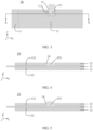
- An existing lithium-ion battery with an embedded tab structure has a region not coated with the active material layer on each of two sides near the center of the positive electrode plate 10. Specifically, referring to FIG. 1 , on the one hand, at a position where the positive electrode current collector 11 is connected to the positive electrode tab 15, each of two sides of the positive electrode current collector 11 is not provided with a positive electrode active material layer. Due to the absence of the positive electrode active material layer in this portion, the energy density of a lithium-ion battery with this embedded tab structure needs to be improved; on the other hand, the provision of the positive electrode tab 15 requires the provision of a groove on each of two sides and an adhesive tape needs to be adhered to the groove.
- an adhesive tape needs also to be adhered to a negative electrode active material layer 22 opposite the grooves, resulting in a thicker thickness at the region adhered with the adhesive tape, thus leading to a poor interface between the positive electrode and negative electrode in the region corresponding to the grooves and a higher risk of lithium precipitation.
- an electrochemical apparatus includes an electrode assembly 1, and the electrode assembly 1 includes a positive electrode plate 10, a negative electrode plate 20, and a separator 30.
- FIG. 3 is a schematic structural diagram of a positive electrode plate according to an embodiment of this application.
- FIG. 4 is a cross-sectional view of a positive electrode plate along its thickness direction at section A-A according to an embodiment of this application.
- the positive electrode plate 10 includes a positive electrode current collector 11, and the positive electrode current collector 11 includes a first surface 111 and a second surface 112, where the first surface 111 and the second surface 112 are two opposite surfaces of the positive electrode current collector 11.
- the positive electrode plate 10 further includes a first positive electrode active material layer 12 disposed on the first surface 111 of the positive electrode current collector 11 and a second positive electrode active material layer 13 disposed on the second surface 112 of the positive electrode current collector 11.
- the first positive electrode active material layer 12 is provided with a first groove 14 exposing the first surface 111, and the positive electrode plate 10 further includes a positive electrode tab 15.
- the positive electrode tab 15 includes a positive electrode connection portion 151, and the positive electrode connection portion 151 is at least partially located within the first groove 14 and welded to the first surface 111.
- the second surface 112 corresponding to the first groove 14 is covered by the second positive electrode active material layer 13, the second positive electrode active material layer 13 includes a second positive electrode active material, and the second positive electrode active material includes element M, where the element M includes at least one of manganese (Mn), iron (Fe), lanthanum (La), zirconium (Zr), or yttrium (Y), and based on a total mass of the second positive electrode active material, a mass percentage of manganese or iron is D%, where 0.02 ⁇ D ⁇ 35.00, and a mass percentage of lanthanum, zirconium, or yttrium is E%, where 0.02 ⁇ E ⁇ 0.20.
- M includes at least one of manganese (Mn), iron (Fe), lanthanum (La), zirconium (Zr), or yttrium (Y)
- a mass percentage of manganese or iron is D%, where 0.02 ⁇ D ⁇ 35.00
- the second surface 112 corresponding to the first groove 14 is the region of an orthographic projection of a sidewall of the first groove 14 along the z direction onto the second surface 112 of the positive electrode current collector 11.
- the second surface 112 corresponding to the first groove 14 being covered by the second positive electrode active material layer 13 means that the entire region of the orthographic projection of the sidewall of the first groove 14 along the z direction onto the second surface 112 of the positive electrode current collector 11 is provided with the second positive electrode active material layer 13.
- the positive electrode connection portion 151 is a portion where the positive electrode tab 15 overlaps with the positive electrode current collector 11.
- the foregoing positive electrode connection portion 151 being at least partially located within the first groove 14 includes two cases where the entire positive electrode connection portion 151 is located within the first groove 14 (as shown in FIG. 4 ) and where part of the positive electrode connection portion 151 is located within the first groove 14 (as shown in FIG. 5 ).
- the inventor has found that for an electrochemical apparatus with an embedded tab structure, at the connection between the tab and the current collector, although the energy density can be improved by applying a positive electrode active material layer on a side of the current collector not welded to the tab, during the welding process of the tab, a significant amount of heat is generated at the welding position, and the heat is quickly conducted from one side of the current collector to another side, affecting the stability of the positive electrode active material layer on the side not welded to the tab. Consequently, this impacts the stability of the positive electrode plate, making the positive electrode plate more prone to aging and even causing the active material layer to peel off during use.
- the active material layer on the side not welded to the tab in the welding region is more prone to issues such as decreased adhesion and powder shedding, causing an increase in the thickness of the welding region, thus creating a thickness difference with the non-welding region.
- large gaps are formed between the positive electrode plate, separator, and negative electrode plate.
- a region of the current collector that is not coated with the active material on two sides is a region where a large number of electrons flow through. Its current density is the highest in the entire positive electrode plate, making it prone to overheating issues.
- the electrochemical apparatus is provided with the first groove exposing the first surface on the first positive electrode active material layer
- the positive electrode connection portion is at least partially located within the first groove and welded to the first surface, forming a single-sided groove embedded tab structure
- the second surface is provided with the second positive electrode active material layer, achieving the retention of an uncoated foil zone on only one side of the positive electrode plate, unlike an existing positive electrode plate with an embedded tab structure that requires the retention of an uncoated foil zone on each of two sides, thereby enhancing the energy density of the electrochemical apparatus.
- this can alleviate the problem of poor interface between the positive electrode and the negative electrode at the position where the tab is provided, reducing the risk of lithium precipitation.
- the second positive electrode active material of this application includes the element M.
- the selection of the element M within the above range and the adjustment of its percentage within the above range can help to improve the thermal stability of the second positive electrode active material, thereby improving the stability of the positive electrode plate.
- This not only can alleviate the aging and powder shedding issues of the positive electrode plate caused by overheating during use, but also can alleviate the adhesion decrease and powder shedding issues exacerbated during soaking in the electrolyte or prolonged cycling, reducing the likelihood of gaps forming between the positive electrode plate, separator, and negative electrode plate due to powder shedding, thus lowering the risk of lithium precipitation of the negative electrode plate and further enhancing the safety performance of the electrochemical apparatus.
- the first positive electrode active material layer 12 and the second positive electrode active material layer 13 of this application are respectively disposed on the first surface 111 and the second surface 112 of the positive electrode current collector 11, where the first surface 111 and the second surface 112 are two opposite surfaces of the positive electrode current collector 11 in the thickness direction.
- the "surface” herein may be an entire region of the positive electrode current collector 11 or a partial region of the positive electrode current collector 11. This is not particularly limited in this application, provided that the objectives of the invention of this application can be achieved.
- the positive electrode connection portion 151 is welded to the first surface 111 through laser welding.
- Laser welding requires energy to be applied only to one side of the positive electrode current collector 11 to melt the welding position, making it more suitable for the electrode plate structure of this application.
- laser irradiation is applied to the welding position, no force is applied to the welding position, which can reduce the impact on the first positive electrode active material layer around the welding position, and reduce the risk of decreased adhesion force and powder shedding of the first positive electrode active material layer caused by welding vibrations.
- laser welding energy is concentrated, which can also reduce the impact of welding heat on the surrounding first positive electrode active material layer.
- laser welding can alleviate the aging problem of an existing positive electrode plate with an embedded tab structure, thereby enhancing the safety of the electrochemical apparatus.
- the selection of the positive electrode current collector 11 and positive electrode tab 15 with thermal conductivities within the above ranges helps to improve the heat dissipation performance of the positive electrode plate, thereby mitigating the aging problem of the positive electrode plate caused by heat accumulation during the use of the electrochemical apparatus, and further enhancing the safety performance of the electrochemical apparatus.
- a material of the positive electrode current collector 11 in this application may include aluminum, aluminum alloy, stainless steel, titanium and titanium alloy, nickel and nickel alloy, and the like; and a material of the positive electrode tab 15 in this application may include aluminum, aluminum alloy, stainless steel, titanium and titanium alloy, nickel and nickel alloy, and the like.
- the electrochemical apparatus includes a packaging bag 40, the electrode assembly 1 is accommodated in the packaging bag 40, and the first surface 111 faces the packaging bag 40.
- the electrode assembly 1 is shaped after manufacturing, and pressure is applied. After the electrode assembly 1 is packaged in the packaging bag 40, pressure is applied during formation to make the positive electrode plate 10 and the negative electrode plate 20 be in close contact with each other.
- the positive electrode tab 15 faces the pressure clamp when pressure is applied, and on another side of the positive electrode tab 15, the second positive electrode active material layer 13 is abutting the positive electrode current collector 11, which enables better force bearing, thereby improving the interface between the positive electrode plate 10, separator 30, and negative electrode plate 20.
- the packaging bag 40 is not particularly limited in this application, and it can be selected according to actual needs, provided that the objectives of the invention of this application can be achieved. For example, an aluminum-plastic film packaging bag or a steel-plastic film packaging bag can be used.
- a separator 30 is disposed between the positive electrode plate 10 and the negative electrode plate 20, the positive electrode plate 10, the separator 30, and the negative electrode plate 20 are stacked together, and the second positive electrode active material layer 13 on the second surface 112 corresponding to the first groove 14 is in contact with the separator 30.
- a groove also needs to be provided on the second surface corresponding to the first groove.
- adhesive tape also needs to be provided on this extra groove provided, and the adhesive tape is in contact with the separator. The presence of the adhesive tape increases the thickness and causes the contact interface to be uneven, thereby increasing the risk of lithium precipitation in the electrochemical apparatus. When no extra groove is provided, adhesive tape needs not to be provided, which also reduces the thickness and improves the interface smoothness, thereby helping to increase the energy density of the electrochemical apparatus.
- the configuration of such a structure can improve the welding strength of the negative electrode tab 24, reducing the risk of failure due to dropping. Furthermore, using ultrasonic welding or resistance welding can protect the negative electrode current collector 21 and the negative electrode active material layer 22 from being damaged.
- the negative electrode active material layer 22 of this application includes graphite, which helps to mitigate the problem of change in material structure of the negative electrode active material layer due to the impact of laser welding heat, thereby reducing the risk of lithium precipitation.
- the first positive electrode active material layer 12 includes a first positive electrode active material, a first binder, and a first conductive agent
- the second positive electrode active material layer 13 further includes a second binder and a second conductive agent
- the first positive electrode active material or the second positive electrode active material includes at least one of lithium cobalt oxide, lithium nickel cobalt manganese oxide, lithium nickel cobalt aluminum oxide, lithium manganese oxide, lithium iron phosphate, lithium iron manganese phosphate, or lithium-rich manganese-based oxide.
- Selection of the above ceramic materials can improve the heat-resistance performance of the first positive electrode active material or the second positive electrode active material, reducing the impact of welding, and helping to enhance the safety performance of the electrochemical apparatus.
- the first binder or the second binder includes at least one of polyvinylidene fluoride, a vinylidene fluoride-fluorinated olefin copolymer, polyvinyl pyrrolidone, polyacrylonitrile, polymethyl acrylate, polytetrafluoroethylene, sodium carboxymethyl cellulose, styrene-butadiene rubber, polyurethane, fluorinated rubber, or polyvinyl alcohol.
- the binder within the above range is applied to the positive electrode plate, the positive electrode plate has good structural stability, which helps to improve the cycling performance and swelling performance of the electrochemical apparatus.
- the first conductive agent or the second conductive agent includes at least one of conductive carbon black (Super P, Ketjenblack, or acetylene black), carbon nanotubes (CNTs), conductive graphite, graphene, or carbon nanofibers.
- the carbon nanotubes may include but are not limited to single-walled carbon nanotubes and/or multi-walled carbon nanotubes.
- the selection of the above conductive agent helps to improve the conductivity of the positive electrode plate. In this application, based on a mass of the first positive electrode active material layer 12, a mass percentage of the first conductive agent is 0.5% to 5%. Based on a mass of the second positive electrode active material layer 13, a mass percentage of the first conductive agent is 0.5% to 5%.
- the first positive electrode active material or the second positive electrode active material may also include a non-metal element, for example, the non-metal element includes at least one of fluorine, phosphorus, boron, or chlorine. These elements can further enhance the stability of the positive electrode active material.
- thickness of the first positive electrode active material layer 12 or the second positive electrode active material layer 13 is not particularly limited, provided that the objectives of the invention in this application can be achieved.
- the thickness of the first positive electrode active material layer 12 or the second positive electrode active material layer 13 ranges from 30 ⁇ m to 120 ⁇ m.
- the second positive electrode active material layer 13 includes a first layer 131 and a second layer 132 stacked together, the first layer 131 is located between the positive electrode current collector 11 and the second layer 132, the second layer 132 includes the second positive electrode active material, and the first layer 131 includes a ceramic material, a third binder, and a third conductive agent;
- the ceramic material includes at least one of hafnium dioxide, strontium titanate, tin dioxide, cesium oxide, magnesium oxide, nickel oxide, calcium oxide, barium oxide, zinc oxide, zirconium oxide, yttrium oxide, aluminum oxide, titanium oxide, silicon dioxide, boehmite, magnesium hydroxide, or aluminum hydroxide.
- Selection of the above ceramic materials can improve the heat-resistance performance of the first positive electrode active material or the second positive electrode active material, reducing the impact of welding. Additionally, when an above ceramic material is selected, a resistance layer with high resistance is provided on a surface of the positive electrode current collector, reducing the risk of an internal short circuit, which could lead to combustion or explosion, thereby enhancing the safety performance of the electrochemical apparatus.
- the third binder includes at least one of polyvinylidene fluoride, a vinylidene fluoride-fluorinated olefin copolymer, polyvinyl pyrrolidone, polyacrylonitrile, polymethyl acrylate, polytetrafluoroethylene, sodium carboxymethyl cellulose, styrene-butadiene rubber, polyurethane, fluorinated rubber, or polyvinyl alcohol.
- the binder within the above range is applied to the positive electrode plate, the positive electrode plate has good structural stability, which helps to improve the cycling performance and swelling performance of the electrochemical apparatus.
- the third conductive agent includes at least one of conductive carbon black (Super P, Ketjenblack, or acetylene black), carbon nanotubes, conductive graphite, graphene, or carbon nanofibers.
- conductive carbon black Super P, Ketjenblack, or acetylene black
- carbon nanotubes carbon nanotubes
- conductive graphite graphene
- carbon nanofibers carbon nanofibers
- the first positive electrode active material layer 12 may include a third layer 121 and a fourth layer 122 stacked together, where the third layer 121 is located between the positive electrode current collector 11 and the fourth layer 122.
- the composition of the third layer 121 may be the same as that of the first layer 131, and the composition of the fourth layer 122 may be the same as that of the second layer 132. Details are not repeated in this application.
- the first layer 131 further includes lithium iron phosphate.
- Lithium iron phosphate has good heat-resistance performance, which helps to improve the heat-resistance performance of the first layer.
- the lithium iron phosphate material has high resistance in the first layer, which can reduce the short-circuit current when a short circuit occurs.
- lithium iron phosphate can provide a certain capacity, which helps to increase the capacity of the electrochemical apparatus.
- lithium iron phosphate has a small particle size at the nanometer scale, which helps to reduce deformation of the positive electrode plate after cold pressing. During welding, this can lower the risk of poor welding or even welding through the positive electrode current collector, thereby enhancing the safety performance of the electrochemical apparatus.
- Preparation methods of the lithium iron phosphate are not particularly limited in this application, provided that the objectives of the invention of this application can be achieved.
- it can be prepared by the following method: Using FeC 2 O 4 ⁇ 8H 2 O, MnCO 3 , NH 4 H 2 PO 4 , Li 2 CO 3 , and ZrO 2 as raw materials, after processes of mixing by ball milling, spray granulating, sintering in a reducing atmosphere containing H 2 , and crushing, manganese and zirconium doped lithium iron phosphate nanopowder is obtained.
- the prepared powder With nitrogen gas used as a protective gas, the prepared powder is vacuum-fed into a rotary furnace, continuously sprayed with a sucrose solution, and subjected to rotary stirring and sintering at 600°C to 800°C for 2 hours to 4 hours to form a carbon-coated layer. After cooling, samples are taken to obtain modified lithium iron phosphate powder, which is the above-mentioned lithium iron phosphate material.
- the average thickness of the carbon-coated layer is 1 ⁇ m.
- the molar ratio of the raw materials can be adjusted to control the mass percentage of Fe, Mn, and Zr in the lithium iron phosphate material.
- the negative electrode active material layer 22 is disposed on the two opposite surfaces of the negative electrode current collector 21 in the thickness direction.
- the "surface” herein may be an entire region of the negative electrode current collector 21, or may be a partial region of the negative electrode current collector 21. This is not particularly limited in this application, provided that the objectives of this application can be achieved.
- the negative electrode current collector 21 is not particularly limited in this application, provided that the objectives of the invention of this application can be achieved.
- the negative electrode current collector 21 may include copper foil, copper alloy foil, nickel foil, stainless steel foil, titanium foil, foamed nickel, foamed copper, a composite current collector, or the like.
- a thickness of the negative electrode current collector 21 is not particularly limited in this application, provided that the objectives of the invention of this application can be achieved.
- the thickness of the negative electrode current collector 21 may range from 4 ⁇ m to 10 ⁇ m.
- the negative electrode active material layer 22 further includes a negative electrode active material.
- a type of the negative electrode active material is not particularly limited in this application, provided that the objectives of the invention of this application can be achieved.
- the negative electrode active material may include at least one of a mesocarbon microbead, hard carbon, soft carbon, silicon, a silicon-carbon composite, SiO x (0 ⁇ x ⁇ 2), a Li-Sn alloy, a Li-Sn-O alloy, Sn, SnO, SnO 2 , spinel-structure lithium titanate Li 4 Ti 5 O 12 , a Li-Al alloy, lithium metal, or the like.
- the negative electrode active material layer 22 may also include a negative electrode conductive agent.
- the negative electrode conductive agent is not particularly limited in this application, provided that the objectives of the invention of this application can be achieved.
- the negative electrode conductive agent may include but is not limited to at least one of conductive carbon black (Super P, Ketjenblack, or acetylene black), carbon nanotubes (CNTs), carbon fibers, graphene, a metal material, or a conductive polymer.
- the above carbon nanotubes may include but are not limited to single-walled carbon nanotubes and/or multi-walled carbon nanotubes.
- the above carbon fibers may include but are not limited to vapor-grown carbon fibers and/or nanocarbon fibers.
- the metal material may include but is not limited to metal powder and/or metal fiber, and specifically, the metal may include but is not limited to at least one of copper, nickel, aluminum, or silver.
- the above conductive polymer may include but is not limited to at least one of polyphenylene derivative, polyaniline, polythiophene, polyacetylene, or polypyrrole. Based on a mass of the negative electrode active material layer 22, a mass percentage of the negative electrode conductive agent is 0.5% to 5%.
- a thickness of the negative electrode active material layer 22 is not particularly limited in this application, provided that the objectives of the invention of this application can be achieved.
- a thickness of a single-sided negative electrode active material layer may range from 30 ⁇ m to 160 ⁇ m.
- a material of the negative electrode tab 24 is not particularly limited in this application, provided that the objectives of the invention of this application can be achieved.
- the material of the negative electrode tab may include copper, a copper alloy, nickel, stainless steel, titanium.
- the electrolyte further includes a non-aqueous solvent.
- the non-aqueous solvent is not particularly limited in this application, provided that the objectives of the invention of this application can be achieved.
- the non-aqueous solvent may include but is not limited to at least of carboxylic acid ester compound, ether compound, or another organic solvent.
- the electrochemical apparatus of this application further includes a separator 30.
- the separator 30 is not particularly limited in this application, provided that the objectives of the invention of this application can be achieved.
- the material of the separator may include but is not limited to at least one of polyethylene (PE), polypropylene (PP), polytetrafluoroethylene-based polyolefin (PO), a polyester film (for example, a polyethylene terephthalate (PET) film), a cellulose film, a polyimide film (PI), a polyamide film (PA), a spandex film or aramid film.
- a material of the base layer includes but is not limited to at least one of polyfluoroolefins, polyethylene terephthalate, polyimide, polyamide-imide, polyvinyl chloride, or polyolefin (for example, biaxially stretched polyolefin heat-shrinkable film), where polyfluoroolefins includes but is not limited to polytetrafluoroethylene or polyvinylidene fluoride.
- the adhesive layer includes an adhesive material, where the adhesive material includes but is not limited to at least one of carboxymethyl cellulose, styrene-butadiene rubber, polyvinylidene fluoride, polytetrafluoroethylene, fluorinated rubber, polyurethane, polypropylene alcohol, sodium polyacrylate, polyetherimide, or acrylate.
- the adhesive material includes but is not limited to at least one of carboxymethyl cellulose, styrene-butadiene rubber, polyvinylidene fluoride, polytetrafluoroethylene, fluorinated rubber, polyurethane, polypropylene alcohol, sodium polyacrylate, polyetherimide, or acrylate.
- a lithium-ion battery was fully discharged and then disassembled.
- the positive electrode plate was taken out, soaked in DMC for 30 minutes, and then cleaned to remove residual impurities on the surface of the positive electrode plate and dried.
- the positive electrode plate was placed in a muffle furnace, calcined at 600°C in an air atmosphere for 4 hours, taken out, and the positive electrode active material on the surface of the current collector was scraped off.
- the particle size corresponding to 50% by volume in the system distribution was measured as D v 50 using a laser particle size analyzer, with the unit ⁇ m.
- the lithium-ion battery was charged at a constant current of 2.6C to 4.2 V, then charged at a constant voltage to 2.35C; charged at a constant current of 2.35C to 4.25 V, then charged at a constant voltage to 2C; charged at a constant current of 2C to 4.3 V, then charged at a constant voltage to 1.5C; charged at a constant current of 1.5C to 4.38 V, then charged at a constant voltage to 1.2C; charged at a constant current of 1.2C to 4.45 V, then charged at a constant voltage to 1C; and charged at a constant current of 1C to 4.48 V, and then charged at a constant voltage to 0.1C.
- the lithium-ion battery After standing for 10 minutes, the lithium-ion battery was discharged: discharged at a constant current of 1.5C to 3.5 V, then discharged at a constant current of 0.7C to 3 V, and finally left for standing for 10 minutes to end one cycle.
- the lithium-ion batteries obtained in the examples or comparative examples were divided into two groups and cycled for 500 and 1000 cycles, respectively, according to the above charging/discharging steps.
- a lithium-ion battery was charged according to the following operating procedure and then discharged to obtain a discharge capacity of the lithium-ion battery: the lithium-ion battery was charged at a constant current of 0.5C to 4.45 V, then charged at a constant voltage of 4.45 V to 0.025C, left for standing for 5 minutes, discharged at a constant current of 0.5C to 3.0 V, and then left for standing for 5 minutes to obtain the discharge capacity C.
- Li(Ni 0.5 Co 0.2 Mn 0.3 )O 2 and lithium manganese oxide (LMO) were mixed at a mass ratio of 6:4 as the positive electrode active material (with D v 50 of 15.1 ⁇ m), and the above positive electrode active material, conductive agent conductive carbon black (Super P), and polyvinylidene fluoride (PVDF) were mixed at a mass ratio of 98:1:1, with N-methylpyrrolidone (NMP) added as a solvent to prepare a positive electrode slurry with a solid content of 75wt%, which was stirred to uniformity. Both the first positive electrode active material layer and the second positive electrode active material layer were prepared using the above positive electrode slurry.
- the positive electrode slurry was evenly applied on the first surface of a 8 ⁇ m-thick positive electrode current collector aluminum foil, dried at 110°C to obtain a positive electrode plate coated with the positive electrode active material on a single side, with a thickness of the first positive electrode active material layer being 110 ⁇ m. Then, the above steps were repeated on the second surface of the positive electrode current collector to obtain a positive electrode plate coated with the positive electrode active material on two sides, with a thickness of the second positive electrode active material layer being 110 ⁇ m. After the coating was completed, the positive electrode plate was cold-pressed and then subjected to tab forming, slitting, laser cleaning, and other processes to obtain a positive electrode plate with a first groove in the middle of the first positive electrode active material layer.
- the aluminum positive electrode tab was welded on the first groove by laser irradiation.
- the dimensions of the positive electrode plate were 81.9 mm ⁇ 1490 mm, and the dimensions of the first groove were 20 mm ⁇ 9 mm.
- Thermal conductivity of the positive electrode current collector (denoted as L) was 217.7 W ⁇ m -1 ⁇ K -1
- thermal conductivity of the positive electrode tab (denoted as R) was 217.7 W ⁇ m -1 ⁇ K -1
- welding strength between the positive electrode connection portion and the positive electrode current collector was 28 N/m
- tensile strength of the positive electrode current collector was 156 MPa.
- the negative electrode active material conductive graphite, conductive carbon black (Super P), sodium carboxymethyl cellulose, and styrene-butadiene rubber were mixed at a mass ratio of 96.4:1.5:0.5:1.6, and then deionized water was added as a solvent to prepare a negative electrode slurry with a solid content of 60wt%, which was stirred to uniformity.
- the negative electrode slurry was uniformly applied on one surface of an 8 ⁇ m-thick negative electrode current collector copper foil, dried at 110°C to obtain a negative electrode plate with a 130 ⁇ m-thick single-sided coating of the negative electrode active material layer, and then the above steps were repeated on another surface of the negative electrode plate to obtain a negative electrode plate coated with the negative electrode active material layer on two sides.
- the negative electrode plate was cold-pressed and then subjected to tab forming, slitting, laser cleaning, and other processes to obtain a negative electrode plate with the second groove in the middle of the negative electrode active material layer on both two sides.
- the copper negative electrode tab was welded on one of the second grooves by ultrasonic processing.
- the dimensions of the negative electrode plate were 83.3 mm ⁇ 1494 mm, and the dimensions of the second groove were 20 mm ⁇ 9 mm.
- EC ethylene carbonate
- PC propylene carbonate
- DEC diethyl carbonate
- EP ethyl propionate
- LiPF 6 lithium salt lithium hexafluorophosphate
- PVDF and aluminum oxide ceramic were mixed at a mass ratio of 9:1, deionized water was added as a solvent to prepare a slurry with a solid content of 12wt% slurry, which was stirred to uniformity, and the slurry was evenly applied on one surface of a 5 ⁇ m-thick polyethylene film substrate, and dried to obtain a separator.
- the positive electrode plate, separator, and negative electrode plate were stacked in sequence, with the separator placed between the positive electrode plate and the negative electrode plate to serve as insulation. Then, single-sided adhesive tape was attached as an insulating layer to the negative electrode active material layer facing the first groove, and to the first positive electrode active material layer and the second positive electrode active material layer facing the second groove, respectively. Then, winding started from one end to obtain an electrode assembly.
- the electrode assembly was placed into an aluminum-plastic film packaging shell, dried in an 85°C vacuum oven for 12 hours to remove moisture, injected with the prepared electrolyte, and subjected to vacuum sealing, standing, formation (charged at a constant current of 0.02C to 3.5 V, then charged at a constant current of 0.1C to 3.9 V), shaping, and capacity process to obtain a lithium-ion battery.
- Example 1-1 The same as Example 1-1 except that in ⁇ Preparation of positive electrode plate>, Li(Ni 0.5 Co 0.2 Mn 0.3 )O 2 was used as the positive electrode active material (with D v 50 as shown in Table 1).
- Example 1-1 The same as Example 1-1 except that in ⁇ Preparation of positive electrode plate>, Mn-doped lithium cobalt oxide, which was obtained by mixing lithium cobalt oxide (LiCoO 2 ) and manganese oxide (MnO 2 ) at a mass ratio of 25:1 and co-sintered at 850°C for 12 hours, was used as the positive electrode active material (with D v 50 as shown in Table 1).
- LiCoO 2 lithium cobalt oxide
- MnO 2 manganese oxide
- Example 1-4 The same as Example 1-4 except that in ⁇ Preparation of positive electrode plate>, LFP, aluminum oxide, conductive carbon black (Super P), and PVDF were mixed at a mass ratio of 96:1:1:2 when preparing the first layer slurry.
- Example 1-1 The same as Example 1-1 except that in ⁇ Preparation of positive electrode plate>, D v 50 of the positive electrode active material was adjusted as shown in Table 2.
- Example 1-9 The same as Example 1-9 except that the thickness of the positive electrode current collector was adjusted according to Table 2.
- Example 1-9 The same as Example 1-9 except that a welding strength of 5 N/m between the positive electrode connection portion and the positive electrode current collector was achieved by adjusting the laser spot diameter size and laser irradiation time.
- Example 1-9 The same as Example 1-9 except that the thickness of the positive electrode current collector was 14 ⁇ m, a welding strength of 35 N/m between the positive electrode connection portion and the positive electrode current collector was achieved by adjusting the laser spot diameter size and laser irradiation time, and the positive electrode current collector had a tensile strength of 50 MPa and was made of aluminum alloy.
- Example 1-9 The same as Example 1-9 except that the material of the positive electrode current collector was aluminum alloy with a thermal conductivity of 400 W ⁇ m -1 ⁇ K -1 , and the material of the positive electrode tab was aluminum alloy with a thermal conductivity of 400 W ⁇ m -1 ⁇ K -1 .
- Example 1-1 The same as Example 1-1 except that Li(Ni 0.5 Co 0.2 Mn 0.3 )O 2 and lithium manganese oxide (LMO) were mixed at a mass ratio of 5:5 as the positive electrode active material.
- Li(Ni 0.5 Co 0.2 Mn 0.3 )O 2 and lithium manganese oxide (LMO) were mixed at a mass ratio of 5:5 as the positive electrode active material.
- Example 1-1 The same as Example 1-1 except that in ⁇ Preparation of positive electrode plate>, LiCoO 2 and MnO 2 were mixed at a mass ratio of 50:1, and co-sintered at 850°C for 4 hours to obtain Mn-doped lithium cobalt oxide as the positive electrode active material.
- Example 1-1 The same as Example 1-1 except that in ⁇ Preparation of positive electrode plate>, FeC 2 O 4 ⁇ 8H 2 O, MnCO 3 , NH 4 H 2 PO 4 , Li 2 CO 3 , and ZrO 2 were used as raw materials, for which the molar ratio was adjusted, and after processes of ball milling, spray granulating, sintering in a reducing atmosphere containing H 2 , and crushing, manganese and zirconium doped lithium iron phosphate nanopowder was obtained; with nitrogen gas used as a protective gas, the prepared powder was vacuum-fed into a rotary kiln, continuously sprayed with a sucrose solution, and sintered at 700°C for 3 hours to form a carbon-coated layer; and after cooling, samples were taken to obtain modified lithium iron phosphate powder, namely lithium iron phosphate (LFP-2), where an average thickness of the carbon-coated layer is 1 ⁇ m; and the obtained LFP-2 was used as the positive electrode active material (with D
- Example 1-4 The same as Example 1-4 except that in ⁇ Preparation of positive electrode plate>, the thickness of the first layer was 2 ⁇ m.
- Example 1-1 The same as Example 1-1 except that in ⁇ Preparation of positive electrode plate>, LiCoO 2 and ZrO 2 were mixed at a mass ratio of 18:1, and co-sintered at 850°C for 5 hours to obtain Zr-doped lithium cobalt oxide as the positive electrode active material.
- Example 1-1 The same as Example 1-1 except that in ⁇ Preparation of positive electrode plate>, LiCoO 2 and ZrO 2 were mixed at a mass ratio of 50:1, and co-sintered at 850°C for 24 hours to obtain Zr-doped lithium cobalt oxide as the positive electrode active material.
- Example 1-1 The same as Example 1-1 except that in ⁇ Preparation of positive electrode plate>, the positive electrode plate with grooves in the middle of both the first positive electrode active material layer and the second positive electrode active material layer was used.
- Example 1-1 to Example 1-12, and Comparative Example 1 to Comparative Example 7 it can be seen that a lithium-ion battery with the single-sided groove-embedded tab structure and the type and percentage of element M in this application has alleviated powder shedding and lithium precipitation issues, and increased energy density, indicating that the lithium-ion battery of this application has excellent safety performance and high energy density.
- Example 1-5 and Comparative Example 3 it can be seen that when the second positive electrode active material includes multiple elements such as Mn, Fe, and Zr, through the controlling of the percentage of element M within the range of this application, the safety performance and energy density of the lithium-ion battery are improved. From Example 1-4 and Comparative Example 4, it can be seen that through the controlling of the percentage of Fe in the second positive electrode active material within the range of this application, the safety performance and energy density of the lithium-ion battery are improved.
- the thermal conductivities of the positive electrode tab and the positive electrode current collector usually may affect the heat dissipation performance of the positive electrode plate. From Example 1-9, Example 2-8, and Example 2-9, it can be seen that through the controlling of the thermal conductivities of the positive electrode tab and the positive electrode current collector within the range of this application, timely heat dissipation can be ensured, avoiding the accumulation of a large amount of heat near the welding region, reducing the risk of loss of adhesion of the binder in the second positive electrode active material layer corresponding to the positive electrode connection portion due to carbonization, thereby alleviating the lithium precipitation issue of the corresponding negative electrode plate near the welding region, resulting in a lithium-ion battery with good safety performance.
Landscapes
- Chemical & Material Sciences (AREA)
- Chemical Kinetics & Catalysis (AREA)
- Electrochemistry (AREA)
- General Chemical & Material Sciences (AREA)
- Engineering & Computer Science (AREA)
- Inorganic Chemistry (AREA)
- Materials Engineering (AREA)
- Manufacturing & Machinery (AREA)
- Crystallography & Structural Chemistry (AREA)
- Secondary Cells (AREA)
- Battery Electrode And Active Subsutance (AREA)
- Connection Of Batteries Or Terminals (AREA)
Abstract
Description
- This application relates to the field of electrochemical technologies, and specifically, to an electrochemical apparatus, a preparation method thereof, and an electronic apparatus.
- Lithium-ion batteries (electrochemical apparatus) have characteristics such as high operating voltage, high energy density, long cycle life, and wide operating temperature range. These excellent characteristics have enabled lithium-ion batteries to be widely used in the three major fields of consumer electronics, power batteries, and energy storage.
- In common wound structure lithium-ion batteries, to reduce the impedance of the lithium-ion battery, instead of using the solution of placing the tabs at the end of the electrode plate, uncoated zones, where the tabs are placed, are provided on two sides at a position closer to the center of the electrode plate. This structure is called an embedded tab structure.
- The purpose of this application is to provide an electrochemical apparatus, a preparation method thereof, and an electronic apparatus to improve the energy density and safety performance of the electrochemical apparatus. Specific technical solutions are as follows:
- According to a first aspect of this application, an electrochemical apparatus is provided, including an electrode assembly, where the electrode assembly includes a positive electrode plate. The positive electrode plate includes a positive electrode current collector and a first positive electrode active material layer disposed on a first surface of the positive electrode current collector and a second positive electrode active material layer disposed on a second surface of the positive electrode current collector, the first surface and the second surface are two opposite surfaces of the positive electrode current collector, and the first positive electrode active material layer is provided with a first groove exposing the first surface. The positive electrode plate further includes a positive electrode tab, the positive electrode tab includes a positive electrode connection portion, the positive electrode connection portion is at least partially located within the first groove and welded to the first surface, and the second surface corresponding to the first groove is covered by the second positive electrode active material layer. The second positive electrode active material layer includes a second positive electrode active material, the second positive electrode active material includes element M, and the element M includes at least one of manganese, iron, lanthanum, zirconium, or yttrium. Based on a total mass of the second positive electrode active material, a mass percentage of manganese or iron is D%, wherein 0.02 ≤ D ≤ 35.00, and a mass percentage of lanthanum, zirconium, or yttrium is E%, wherein 0.02 ≤ E ≤ 0.20.
- Beneficial effects of the embodiments of this application: In this application, the electrochemical apparatus is provided with the first groove exposing the first surface on the first positive electrode active material layer, the positive electrode connection portion is at least partially located within the first groove and welded to the first surface, forming a single-sided groove embedded tab structure, and the second surface is provided with the second positive electrode active material layer, achieving the retention of an uncoated foil zone on only one side of the positive electrode plate, unlike an existing positive electrode plate with an embedded tab structure that requires the retention of an uncoated foil zone on each of two sides, thereby enhancing the energy density of the electrochemical apparatus. Additionally, this can alleviate the problem of poor interface between the positive electrode and the negative electrode at the position where the tab is provided, reducing the risk of lithium precipitation. At the same time, the second positive electrode active material of this application includes element M. The selection of the element M within the above range and the adjustment of its percentage within the above range can help to improve the thermal stability of the second positive electrode active material, thereby alleviating the aging problem of the positive electrode plate and enhancing the safety performance of the electrochemical apparatus. Using the technical solution of this application can achieve improved energy density and safety performance of the electrochemical apparatus.
- In an embodiment of this application, the positive electrode connection portion is welded to the first surface through laser welding. Laser welding requires energy to be applied only to one side of the positive electrode current collector to melt the welding position, making it more suitable for the electrode plate structure of this application. Through laser welding, the aging problem of the existing embedded tab structure positive electrode plate can be improved, thereby enhancing the safety of the electrochemical apparatus.
- In an embodiment of this application, the positive electrode connection portion and the first surface are welded to form a welding portion, wherein the welding portion penetrates through the positive electrode tab and at least partially penetrates the positive electrode current collector. Through the provision of such a structure, connection strength between the positive electrode connection portion and the positive electrode current collector is further enhanced, thereby further improving the anti-detachment capability of the positive electrode tab and enhancing the safety performance of the electrochemical apparatus.
- In an embodiment of this application, Dv50 of the second positive electrode active material is B µm, welding strength between the positive electrode connection portion and the positive electrode current collector is A N/m, a thickness of the positive electrode current collector is T µm, and tensile strength of the positive electrode current collector is S MPa, wherein B/T × A < S. The adjustment of B, A, T, and S to satisfy the above relationship helps to improve the connection strength between the positive electrode connection portion and the positive electrode current collector, thereby enhancing the anti-detachment capability of the positive electrode tab and improving the safety performance of the electrochemical apparatus.
- In an embodiment of this application, 0.5 ≤ B ≤ 18. The adjustment of B within the above range helps to reduce deformation of the positive electrode plate after cold pressing. The adjustment of A within the range of 5 ≤ A ≤ 50 can reduce a risk of damage to the positive electrode current collector or detachment of the surface active material due to excessive welding energy, as well as a risk of insufficient connection strength between the positive electrode current collector and the positive electrode tab due to insufficient welding energy. The adjustment of T and S within the ranges of 4 ≤ T ≤ 14 and 50 ≤ S ≤ 500 helps to improve the bearing capacity of the positive electrode current collector, thereby enhancing the anti-detachment capability of the positive electrode tab and improving the safety performance of the electrochemical apparatus.
- In an embodiment of this application, a thermal conductivity of the positive electrode current collector ranges from 30 W·m-1·K-1 to 400 W·m-1·K-1, preferably 200 W·m-1·K-1 to 250 W·m-1·K-1; and a thermal conductivity of the positive electrode tab ranges from 30 W·m-1·K-1 to 400 W·m-1·K-1, preferably 200 W·m-1·K-1 to 250 W. m-1·K-1. The selection of the positive electrode current collector and positive electrode tab with thermal conductivities within the above ranges helps to improve the heat dissipation performance of the positive electrode plate, thereby mitigating the aging problem of the positive electrode plate caused by heat accumulation during the use of the electrochemical apparatus, and further enhancing the safety performance of the electrochemical apparatus.
- In an embodiment of this application, the electrochemical apparatus includes a packaging bag, the electrode assembly is accommodated in the packaging bag, and the first surface faces the packaging bag, thereby improving the interfaces between the positive electrode plate, separator, and negative electrode plate.
- In an embodiment of this application, the electrode assembly further includes a negative electrode plate and a separator disposed between the positive electrode plate and the negative electrode plate, the positive electrode plate, the separator, and the negative electrode plate are stacked together, and the second positive electrode active material layer on the second surface corresponding to the first groove is in contact with the separator. When such a structure is configured, an extra groove is not provided, therefore adhesive tape needs not to be provided, which also reduces the thickness and improves the interface smoothness, thereby helping to increase the energy density of the electrochemical apparatus.
- In an embodiment of this application, the negative electrode plate includes a negative electrode current collector and negative electrode active material layers disposed on two surfaces of the negative electrode current collector, the negative electrode active material layers on the two surfaces of the negative electrode current collector each are provided with a second groove exposing the surface of the negative electrode current collector, and the second groove on one side of the negative electrode current collector is opposite the second groove on another side of the negative electrode current collector. The negative electrode plate further includes a negative electrode tab, wherein the negative electrode tab includes a negative electrode connection portion, and the negative electrode connection portion is at least partially located within the second groove and welded to the negative electrode current collector, the welding including ultrasonic welding or resistance welding. The configuration of such a structure can improve the welding strength of the negative electrode tab, reducing the risk of failure due to dropping. Furthermore, using ultrasonic welding or resistance welding can protect the negative electrode current collector and the negative electrode active material layer from being damaged. The negative electrode active material layer of this application includes graphite, which helps to mitigate the problem of change in material structure of the negative electrode active material layer due to the impact of laser welding heat, thereby reducing the risk of lithium precipitation.
- In an embodiment of this application, the first positive electrode active material layer includes a first positive electrode active material, a first binder, and a first conductive agent, and the second positive electrode active material layer further includes a second binder and a second conductive agent; and the first positive electrode active material or the second positive electrode active material includes at least one of lithium cobalt oxide, lithium nickel cobalt manganese oxide, lithium nickel cobalt aluminum oxide, lithium manganese oxide, lithium iron phosphate, lithium iron manganese phosphate, or lithium-rich manganese-based oxide. Selection of the above ceramic materials can improve the heat-resistance performance of the first positive electrode active material or the second positive electrode active material, reducing the impact of welding, and helping to enhance the safety performance of the electrochemical apparatus. The first binder or the second binder includes at least one of polyvinylidene fluoride, a vinylidene fluoride-fluorinated olefin copolymer, polyvinyl pyrrolidone, polyacrylonitrile, polymethyl acrylate, polytetrafluoroethylene, sodium carboxymethyl cellulose, styrene-butadiene rubber, polyurethane, fluorinated rubber, or polyvinyl alcohol. When the binder within the above range is applied to the positive electrode plate, the positive electrode plate has good structural stability, which helps to improve the cycling performance and swelling performance of the electrochemical apparatus. The first conductive agent or the second conductive agent includes at least one of conductive carbon black, carbon nanotubes, conductive graphite, graphene, or carbon nanofibers. The selection of the above conductive agent helps to improve the conductivity of the positive electrode plate.
- In an embodiment of this application, the second positive electrode active material layer includes a first layer and a second layer stacked together, the first layer is located between the positive electrode current collector and the second layer, the second layer includes the second positive electrode active material, and the first layer includes a ceramic material, a third binder, and a third conductive agent; The ceramic material includes at least one of hafnium dioxide, strontium titanate, tin dioxide, cesium oxide, magnesium oxide, nickel oxide, calcium oxide, barium oxide, zinc oxide, zirconium oxide, yttrium oxide, aluminum oxide, titanium oxide, silicon dioxide, boehmite, magnesium hydroxide, or aluminum hydroxide. Selection of the above ceramic materials can improve the heat-resistance performance of the first positive electrode active material or the second positive electrode active material, reducing the impact of welding. Additionally, when the above ceramic materials are selected, a resistance layer with high resistance is adhered on a surface of the positive electrode current collector, reducing the risk of an internal short circuit caused by direct contact between the positive electrode current collector and the negative electrode active material layer, which could lead to combustion or explosion, thereby enhancing the safety performance of the electrochemical apparatus. The third binder includes at least one of polyvinylidene fluoride, a vinylidene fluoride-fluorinated olefin copolymer, polyvinyl pyrrolidone, polyacrylonitrile, polymethyl acrylate, polytetrafluoroethylene, sodium carboxymethyl cellulose, styrene-butadiene rubber, polyurethane, fluorinated rubber, or polyvinyl alcohol. When the binder within the above range is applied to the positive electrode plate, the positive electrode plate has good structural stability, which helps to improve the cycling performance and swelling performance of the electrochemical apparatus. The third conductive agent includes at least one of conductive carbon black, carbon nanotubes, conductive graphite, graphene, or carbon nanofibers. The selection of the above conductive agent helps to improve the conductivity of the positive electrode plate.
- In an embodiment of this application, the first layer further includes lithium iron phosphate. Lithium iron phosphate has good heat-resistance performance, which helps to improve the heat-resistance performance of the first layer. Additionally, the lithium iron phosphate material has high resistance in the first layer, which can increase the short-circuit resistance and reduce the short-circuit current when a short circuit occurs due to contact between the positive electrode and negative electrode under mechanical abuse conditions. Moreover, lithium iron phosphate can undergo lithium intercalation and deintercalation, which helps to increase the capacity of the electrochemical apparatus. Furthermore, lithium iron phosphate has a small particle size at the nanometer scale, which helps to reduce deformation of the positive electrode plate after rolling. During welding, this can lower the risk of poor welding or even welding through the positive electrode current collector, thereby enhancing the safety performance of the electrochemical apparatus.
- A second aspect of this application provides a preparation method of an electrochemical apparatus, including:
- providing a positive electrode current collector, disposing a first positive electrode active material layer on a first surface of the positive electrode current collector, and disposing a second positive electrode active material layer on a second surface of the positive electrode current collector, wherein the first surface and the second surface are two opposite surfaces of the positive electrode current collector, and the first positive electrode active material layer is provided with a first groove exposing the first surface; and
- providing a positive electrode tab, and welding the positive electrode tab to the first surface exposed by the first groove, such that a positive electrode connection portion of the positive electrode tab is connected to the first surface, wherein the second surface corresponding to the first groove is covered by the second positive electrode active material layer, the second positive electrode active material layer includes a second positive electrode active material, the second positive electrode active material includes element M, the element M includes at least one of manganese, iron, lanthanum, zirconium, or yttrium, and Based on a total mass of the second positive electrode active material, a mass percentage of manganese or iron is D%, wherein 0.02 ≤ D ≤ 35.00, and a mass percentage of lanthanum, zirconium, or yttrium is E%, wherein 0.02 ≤ E ≤ 0.20.
- The electrochemical apparatus obtained by the preparation method provided in the second aspect of this application can improve the energy density and safety performance of the electrochemical apparatus.
- In an embodiment of this application, laser irradiation is applied to the positive electrode connection portion to weld the positive electrode connection portion to the first surface, which can ensure that the connection strength between the positive electrode connection portion and the positive electrode current collector meets the requirements, thereby improving the anti-detachment capability of the positive electrode tab, and enhancing the safety performance of the electrochemical apparatus.
- A third aspect of this application provides an electronic apparatus, including the electrochemical apparatus according to the first aspect of this application. The electrochemical apparatus provided in this application has high energy density and good safety performance, enabling the electronic apparatus in this application to have a long battery life and service life.
- This application provides an electrochemical apparatus, a preparation method thereof, and an electronic apparatus, where the electrochemical apparatus is provided with the first groove exposing the first surface on the first positive electrode active material layer, the positive electrode connection portion is at least partially located within the first groove and welded to the first surface, forming a single-sided groove embedded tab structure, and the second surface is provided with the second positive electrode active material layer, achieving the retention of an uncoated foil zone on only one side of the positive electrode plate, unlike an existing positive electrode plate with an embedded tab structure that requires the retention of an uncoated foil zone on two sides, thereby enhancing the energy density of the electrochemical apparatus. Additionally, this can alleviate the problem of poor interface between the positive electrode and the negative electrode at the position where the tab is provided, reducing the risk of lithium precipitation. At the same time, the second positive electrode active material of this application includes the element M. The selection of the element M within the range of this application and the adjustment of its percentage within the range of this application help to improve the thermal stability of the positive electrode active material, thereby alleviating the aging problem of the positive electrode plate with the embedded tab structure, and enhancing the safety performance of the electrochemical apparatus. Using the technical solution of this application can achieve improved energy density and safety performance of the electrochemical apparatus.
- To describe the technical solutions in some embodiments of this application and in the prior art more clearly, the following briefly describes the accompanying drawings required for describing some embodiments and the prior art. Apparently, the accompanying drawings in the following descriptions show only some embodiments of this application, and persons of ordinary skill in the art may still derive other drawings from these accompanying drawings.
-
FIG. 1 is a schematic structural diagram of an electrode assembly with an embedded tab structure in the prior art; -
FIG. 2 is a schematic structural diagram of an electrochemical apparatus according to an embodiment of this application; -
FIG. 3 is a schematic structural diagram of a positive electrode plate according to an embodiment of this application; -
FIG. 4 is a cross-sectional view of a positive electrode plate along its thickness direction at section A-A according to an embodiment of this application; -
FIG. 5 is a cross-sectional view of a positive electrode plate along its thickness direction at section A-A according to another embodiment of this application; -
FIG. 6 is a locally enlarged view of a welding portion formed by welding a positive electrode connection portion and a first surface according to an embodiment of this application; and -
FIG. 7 is a cross-sectional view of a positive electrode plate along its thickness direction at section A-A according to another embodiment of this application. - Electrode assembly-1, positive electrode plate-10, positive electrode current collector-11, first positive electrode active material layer-12, second positive electrode active material layer-13, first groove-14, positive electrode tab-15, welding portion-16, negative electrode plate-20, negative electrode current collector-21, negative electrode active material layer-22, second groove-23, negative electrode tab-24, separator-30, packaging bag-40, first surface-111, second surface-112, third layer-121, fourth layer-122, first layer-131, second layer-132, positive electrode connection portion-151, and negative electrode connection portion-241.
- To make the objectives, technical solutions, and advantages of this application more comprehensible, the following describes this application in detail with reference to accompanying drawings and embodiments. Apparently, the described embodiments are merely some but not all of the embodiments of this application. All other embodiments obtained by persons of ordinary skill in the art based on the embodiments of this application shall fall within the protection scope of this application.
- In the specific embodiments of this application, a lithium-ion battery is used as an example of an electrochemical apparatus to explain this application. However, the electrochemical apparatus in this application is not limited to the lithium-ion battery, it may also be sodium-ion battery, and the like.
- In this application, a thickness direction of the electrode plate in an unfolded state is defined as a z direction, and the two directions perpendicular to the z direction are defined as an x direction and a y direction, where the x direction and the y direction are perpendicular to each other. The x direction is an extension direction of a long side after the electrode plate is unfolded, and the y direction is an extension direction of a short side after the electrode plate is unfolded. In this application, a thickness direction of the electrode plate in a wound state is defined as a z' direction, and the two directions perpendicular to the z' direction are defined as an x' direction and a y' direction, where the x' direction and the y' direction are perpendicular to each other. The y' direction is an extension direction of a winding axis of the electrode plate, and the x' direction is a direction perpendicular to the y' direction in a plane of the electrode plate. The electrode plate includes a positive electrode plate and a negative electrode plate.
- An existing lithium-ion battery with an embedded tab structure has a region not coated with the active material layer on each of two sides near the center of the
positive electrode plate 10. Specifically, referring toFIG. 1 , on the one hand, at a position where the positive electrodecurrent collector 11 is connected to thepositive electrode tab 15, each of two sides of the positive electrodecurrent collector 11 is not provided with a positive electrode active material layer. Due to the absence of the positive electrode active material layer in this portion, the energy density of a lithium-ion battery with this embedded tab structure needs to be improved; on the other hand, the provision of thepositive electrode tab 15 requires the provision of a groove on each of two sides and an adhesive tape needs to be adhered to the groove. In addition, an adhesive tape needs also to be adhered to a negative electrode active material layer 22 opposite the grooves, resulting in a thicker thickness at the region adhered with the adhesive tape, thus leading to a poor interface between the positive electrode and negative electrode in the region corresponding to the grooves and a higher risk of lithium precipitation. - In view of this, according to a first aspect of this application, an electrochemical apparatus is provided. As shown in
FIG. 2 , the electrochemical apparatus includes anelectrode assembly 1, and theelectrode assembly 1 includes apositive electrode plate 10, anegative electrode plate 20, and aseparator 30.FIG. 3 is a schematic structural diagram of a positive electrode plate according to an embodiment of this application.FIG. 4 is a cross-sectional view of a positive electrode plate along its thickness direction at section A-A according to an embodiment of this application. Referring toFIG. 3 and FIG. 4 , thepositive electrode plate 10 includes a positive electrodecurrent collector 11, and the positive electrodecurrent collector 11 includes afirst surface 111 and asecond surface 112, where thefirst surface 111 and thesecond surface 112 are two opposite surfaces of the positive electrodecurrent collector 11. Thepositive electrode plate 10 further includes a first positive electrodeactive material layer 12 disposed on thefirst surface 111 of the positive electrodecurrent collector 11 and a second positive electrodeactive material layer 13 disposed on thesecond surface 112 of the positive electrodecurrent collector 11. The first positive electrodeactive material layer 12 is provided with afirst groove 14 exposing thefirst surface 111, and thepositive electrode plate 10 further includes apositive electrode tab 15. Thepositive electrode tab 15 includes a positiveelectrode connection portion 151, and the positiveelectrode connection portion 151 is at least partially located within thefirst groove 14 and welded to thefirst surface 111. Thesecond surface 112 corresponding to thefirst groove 14 is covered by the second positive electrodeactive material layer 13, the second positive electrodeactive material layer 13 includes a second positive electrode active material, and the second positive electrode active material includes element M, where the element M includes at least one of manganese (Mn), iron (Fe), lanthanum (La), zirconium (Zr), or yttrium (Y), and based on a total mass of the second positive electrode active material, a mass percentage of manganese or iron is D%, where 0.02 ≤ D ≤ 35.00, and a mass percentage of lanthanum, zirconium, or yttrium is E%, where 0.02 ≤ E ≤ 0.20. - In this application, the
second surface 112 corresponding to thefirst groove 14 is the region of an orthographic projection of a sidewall of thefirst groove 14 along the z direction onto thesecond surface 112 of the positive electrodecurrent collector 11. In this application, thesecond surface 112 corresponding to thefirst groove 14 being covered by the second positive electrodeactive material layer 13 means that the entire region of the orthographic projection of the sidewall of thefirst groove 14 along the z direction onto thesecond surface 112 of the positive electrodecurrent collector 11 is provided with the second positive electrodeactive material layer 13. - In this application, the positive
electrode connection portion 151 is a portion where thepositive electrode tab 15 overlaps with the positive electrodecurrent collector 11. The foregoing positiveelectrode connection portion 151 being at least partially located within thefirst groove 14 includes two cases where the entire positiveelectrode connection portion 151 is located within the first groove 14 (as shown inFIG. 4 ) and where part of the positiveelectrode connection portion 151 is located within the first groove 14 (as shown inFIG. 5 ). - The inventor has found that for an electrochemical apparatus with an embedded tab structure, at the connection between the tab and the current collector, although the energy density can be improved by applying a positive electrode active material layer on a side of the current collector not welded to the tab, during the welding process of the tab, a significant amount of heat is generated at the welding position, and the heat is quickly conducted from one side of the current collector to another side, affecting the stability of the positive electrode active material layer on the side not welded to the tab. Consequently, this impacts the stability of the positive electrode plate, making the positive electrode plate more prone to aging and even causing the active material layer to peel off during use. In an electrochemical apparatus made of such a positive electrode plate, after multiple charge and discharge cycles, the active material layer on the side not welded to the tab in the welding region is more prone to issues such as decreased adhesion and powder shedding, causing an increase in the thickness of the welding region, thus creating a thickness difference with the non-welding region. In the vicinity of the location where the thickness difference occurs, large gaps are formed between the positive electrode plate, separator, and negative electrode plate. During the charge and discharge cycles of the electrochemical apparatus, side reactions and impedance increase in the gaps, leading to an increased risk of lithium precipitation in the electrochemical apparatus. In addition, during the charge and discharge cycles of the electrochemical apparatus, a region of the current collector that is not coated with the active material on two sides (that is, an uncoated foil zone) is a region where a large number of electrons flow through. Its current density is the highest in the entire positive electrode plate, making it prone to overheating issues.
- It was found based on the above research that: in this application, the electrochemical apparatus is provided with the first groove exposing the first surface on the first positive electrode active material layer, the positive electrode connection portion is at least partially located within the first groove and welded to the first surface, forming a single-sided groove embedded tab structure, and the second surface is provided with the second positive electrode active material layer, achieving the retention of an uncoated foil zone on only one side of the positive electrode plate, unlike an existing positive electrode plate with an embedded tab structure that requires the retention of an uncoated foil zone on each of two sides, thereby enhancing the energy density of the electrochemical apparatus. Additionally, this can alleviate the problem of poor interface between the positive electrode and the negative electrode at the position where the tab is provided, reducing the risk of lithium precipitation. Meanwhile, the second positive electrode active material of this application includes the element M. The selection of the element M within the above range and the adjustment of its percentage within the above range can help to improve the thermal stability of the second positive electrode active material, thereby improving the stability of the positive electrode plate. This not only can alleviate the aging and powder shedding issues of the positive electrode plate caused by overheating during use, but also can alleviate the adhesion decrease and powder shedding issues exacerbated during soaking in the electrolyte or prolonged cycling, reducing the likelihood of gaps forming between the positive electrode plate, separator, and negative electrode plate due to powder shedding, thus lowering the risk of lithium precipitation of the negative electrode plate and further enhancing the safety performance of the electrochemical apparatus.
- As shown in
FIG. 4 , the first positive electrodeactive material layer 12 and the second positive electrodeactive material layer 13 of this application are respectively disposed on thefirst surface 111 and thesecond surface 112 of the positive electrodecurrent collector 11, where thefirst surface 111 and thesecond surface 112 are two opposite surfaces of the positive electrodecurrent collector 11 in the thickness direction. The "surface" herein may be an entire region of the positive electrodecurrent collector 11 or a partial region of the positive electrodecurrent collector 11. This is not particularly limited in this application, provided that the objectives of the invention of this application can be achieved. - In an embodiment of this application, the positive
electrode connection portion 151 is welded to thefirst surface 111 through laser welding. Laser welding requires energy to be applied only to one side of the positive electrodecurrent collector 11 to melt the welding position, making it more suitable for the electrode plate structure of this application. When laser irradiation is applied to the welding position, no force is applied to the welding position, which can reduce the impact on the first positive electrode active material layer around the welding position, and reduce the risk of decreased adhesion force and powder shedding of the first positive electrode active material layer caused by welding vibrations. Furthermore, laser welding energy is concentrated, which can also reduce the impact of welding heat on the surrounding first positive electrode active material layer. Thus, laser welding can alleviate the aging problem of an existing positive electrode plate with an embedded tab structure, thereby enhancing the safety of the electrochemical apparatus. - In an embodiment of this application, as shown in
FIG. 6 , the positiveelectrode connection portion 151 and thefirst surface 111 are welded to form awelding portion 16, wherein thewelding portion 16 penetrates through thepositive electrode tab 15 and at least partially penetrates the positive electrodecurrent collector 11. Through the provision of such a structure, connection strength between the positiveelectrode connection portion 151 and the positive electrodecurrent collector 11 is further enhanced, thereby further improving the anti-detachment capability of the positive electrode tab and enhancing the safety performance of the electrochemical apparatus. - In an embodiment of this application, Dv50 of the second positive electrode active material is B µm, welding strength between the positive
electrode connection portion 151 and the positive electrodecurrent collector 11 is A N/m, a thickness of the positive electrodecurrent collector 11 is T µm, and tensile strength of the positive electrodecurrent collector 11 is S MPa, wherein B/T × A < S. The adjustment of B, A, T, and S to satisfy the above relationship helps to improve the connection strength between the positiveelectrode connection portion 151 and the positive electrodecurrent collector 11, thereby enhancing the anti-detachment capability of the positive electrode tab and improving the safety performance of the electrochemical apparatus. In this application, Dv50 is a particle size where the cumulative distribution by volume reaches 50% as counted from the small particle size side. In this application, screening tools can be used to select positive electrode active materials that meet different Dv50 requirements. - In an embodiment of this application, 0.5 ≤ B ≤ 18. The adjustment of B within the above range helps to reduce deformation of the positive electrode plate after cold pressing. The adjustment of A within the range of 5 ≤ A ≤ 50 can reduce a risk of damage to the positive electrode
current collector 11 or detachment of the surface active material due to excessive welding energy, as well as a risk of insufficient connection strength between the positive electrodecurrent collector 11 and thepositive electrode tab 15 due to insufficient welding energy. The adjustment of T and S within the ranges of 4 ≤ T ≤ 14 and 50 ≤ S ≤ 500 helps to improve the bearing capacity of the positive electrodecurrent collector 11, thereby enhancing the anti-detachment capability of the positive electrode tab and improving the safety performance of the electrochemical apparatus. - In an embodiment of this application, a thermal conductivity of the positive electrode
current collector 11 ranges from 30 W·m-1·K-1 to 400 W·m-1·K-1; and a thermal conductivity of thepositive electrode tab 15 ranges from 30 W·m-1·K-1 to 400 W·m-1·K-1. Preferably, a thermal conductivity of the positive electrodecurrent collector 11 ranges from 200 W·m-1·K-1 to 250 W·m-1·K-1; and a thermal conductivity of thepositive electrode tab 15 ranges from 200 W·m-1·K-1 to 250 W·m-1·K-1. The selection of the positive electrodecurrent collector 11 andpositive electrode tab 15 with thermal conductivities within the above ranges helps to improve the heat dissipation performance of the positive electrode plate, thereby mitigating the aging problem of the positive electrode plate caused by heat accumulation during the use of the electrochemical apparatus, and further enhancing the safety performance of the electrochemical apparatus. - From a perspective of improving the heat dissipation performance of the
positive electrode plate 10, a material of the positive electrodecurrent collector 11 in this application may include aluminum, aluminum alloy, stainless steel, titanium and titanium alloy, nickel and nickel alloy, and the like; and a material of thepositive electrode tab 15 in this application may include aluminum, aluminum alloy, stainless steel, titanium and titanium alloy, nickel and nickel alloy, and the like. - In an embodiment of this application, as shown in
FIG. 2 , the electrochemical apparatus includes apackaging bag 40, theelectrode assembly 1 is accommodated in thepackaging bag 40, and thefirst surface 111 faces thepackaging bag 40. Theelectrode assembly 1 is shaped after manufacturing, and pressure is applied. After theelectrode assembly 1 is packaged in thepackaging bag 40, pressure is applied during formation to make thepositive electrode plate 10 and thenegative electrode plate 20 be in close contact with each other. With thefirst surface 111 facing thepackaging bag 40, thepositive electrode tab 15 faces the pressure clamp when pressure is applied, and on another side of thepositive electrode tab 15, the second positive electrodeactive material layer 13 is abutting the positive electrodecurrent collector 11, which enables better force bearing, thereby improving the interface between thepositive electrode plate 10,separator 30, andnegative electrode plate 20. Thepackaging bag 40 is not particularly limited in this application, and it can be selected according to actual needs, provided that the objectives of the invention of this application can be achieved. For example, an aluminum-plastic film packaging bag or a steel-plastic film packaging bag can be used. - In an embodiment of this application, as shown in
FIG. 2 , aseparator 30 is disposed between thepositive electrode plate 10 and thenegative electrode plate 20, thepositive electrode plate 10, theseparator 30, and thenegative electrode plate 20 are stacked together, and the second positive electrodeactive material layer 13 on thesecond surface 112 corresponding to thefirst groove 14 is in contact with theseparator 30. In an existing electrochemical apparatus with an embedded tab structure, a groove also needs to be provided on the second surface corresponding to the first groove. Moreover, adhesive tape also needs to be provided on this extra groove provided, and the adhesive tape is in contact with the separator. The presence of the adhesive tape increases the thickness and causes the contact interface to be uneven, thereby increasing the risk of lithium precipitation in the electrochemical apparatus. When no extra groove is provided, adhesive tape needs not to be provided, which also reduces the thickness and improves the interface smoothness, thereby helping to increase the energy density of the electrochemical apparatus. - In an embodiment of this application, as shown in
FIG. 2 , thenegative electrode plate 20 includes a negative electrodecurrent collector 21 and negative electrode active material layers 22 disposed on two surfaces of the negative electrodecurrent collector 21, the negative electrode active material layers 22 on the two surfaces of the negative electrodecurrent collector 21 each are provided with asecond groove 23 exposing the surface of the negative electrodecurrent collector 21, and thesecond groove 23 on one side of the negative electrodecurrent collector 21 is opposite thesecond groove 23 on another side of the negative electrodecurrent collector 21. Thenegative electrode plate 20 further includes anegative electrode tab 24, wherein thenegative electrode tab 24 includes a negativeelectrode connection portion 241, and the negativeelectrode connection portion 241 is at least partially located within thesecond groove 23 and welded to the negative electrodecurrent collector 21, the welding including ultrasonic welding or resistance welding. The configuration of such a structure can improve the welding strength of thenegative electrode tab 24, reducing the risk of failure due to dropping. Furthermore, using ultrasonic welding or resistance welding can protect the negative electrodecurrent collector 21 and the negative electrode active material layer 22 from being damaged. The negative electrode active material layer 22 of this application includes graphite, which helps to mitigate the problem of change in material structure of the negative electrode active material layer due to the impact of laser welding heat, thereby reducing the risk of lithium precipitation. - In an embodiment of this application, the first positive electrode
active material layer 12 includes a first positive electrode active material, a first binder, and a first conductive agent, and the second positive electrodeactive material layer 13 further includes a second binder and a second conductive agent; and the first positive electrode active material or the second positive electrode active material includes at least one of lithium cobalt oxide, lithium nickel cobalt manganese oxide, lithium nickel cobalt aluminum oxide, lithium manganese oxide, lithium iron phosphate, lithium iron manganese phosphate, or lithium-rich manganese-based oxide. Selection of the above ceramic materials can improve the heat-resistance performance of the first positive electrode active material or the second positive electrode active material, reducing the impact of welding, and helping to enhance the safety performance of the electrochemical apparatus. The first binder or the second binder includes at least one of polyvinylidene fluoride, a vinylidene fluoride-fluorinated olefin copolymer, polyvinyl pyrrolidone, polyacrylonitrile, polymethyl acrylate, polytetrafluoroethylene, sodium carboxymethyl cellulose, styrene-butadiene rubber, polyurethane, fluorinated rubber, or polyvinyl alcohol. When the binder within the above range is applied to the positive electrode plate, the positive electrode plate has good structural stability, which helps to improve the cycling performance and swelling performance of the electrochemical apparatus. The first conductive agent or the second conductive agent includes at least one of conductive carbon black (Super P, Ketjenblack, or acetylene black), carbon nanotubes (CNTs), conductive graphite, graphene, or carbon nanofibers. The carbon nanotubes may include but are not limited to single-walled carbon nanotubes and/or multi-walled carbon nanotubes. The selection of the above conductive agent helps to improve the conductivity of the positive electrode plate. In this application, based on a mass of the first positive electrodeactive material layer 12, a mass percentage of the first conductive agent is 0.5% to 5%. Based on a mass of the second positive electrodeactive material layer 13, a mass percentage of the first conductive agent is 0.5% to 5%. - In this application, the first positive electrode active material or the second positive electrode active material may also include a non-metal element, for example, the non-metal element includes at least one of fluorine, phosphorus, boron, or chlorine. These elements can further enhance the stability of the positive electrode active material. In this application, thickness of the first positive electrode
active material layer 12 or the second positive electrodeactive material layer 13 is not particularly limited, provided that the objectives of the invention in this application can be achieved. For example, the thickness of the first positive electrodeactive material layer 12 or the second positive electrodeactive material layer 13 ranges from 30 µm to 120 µm. - In an embodiment of this application, as shown in
FIG. 7 , the second positive electrodeactive material layer 13 includes a first layer 131 and asecond layer 132 stacked together, the first layer 131 is located between the positive electrodecurrent collector 11 and thesecond layer 132, thesecond layer 132 includes the second positive electrode active material, and the first layer 131 includes a ceramic material, a third binder, and a third conductive agent; The ceramic material includes at least one of hafnium dioxide, strontium titanate, tin dioxide, cesium oxide, magnesium oxide, nickel oxide, calcium oxide, barium oxide, zinc oxide, zirconium oxide, yttrium oxide, aluminum oxide, titanium oxide, silicon dioxide, boehmite, magnesium hydroxide, or aluminum hydroxide. Selection of the above ceramic materials can improve the heat-resistance performance of the first positive electrode active material or the second positive electrode active material, reducing the impact of welding. Additionally, when an above ceramic material is selected, a resistance layer with high resistance is provided on a surface of the positive electrode current collector, reducing the risk of an internal short circuit, which could lead to combustion or explosion, thereby enhancing the safety performance of the electrochemical apparatus. The third binder includes at least one of polyvinylidene fluoride, a vinylidene fluoride-fluorinated olefin copolymer, polyvinyl pyrrolidone, polyacrylonitrile, polymethyl acrylate, polytetrafluoroethylene, sodium carboxymethyl cellulose, styrene-butadiene rubber, polyurethane, fluorinated rubber, or polyvinyl alcohol. When the binder within the above range is applied to the positive electrode plate, the positive electrode plate has good structural stability, which helps to improve the cycling performance and swelling performance of the electrochemical apparatus. The third conductive agent includes at least one of conductive carbon black (Super P, Ketjenblack, or acetylene black), carbon nanotubes, conductive graphite, graphene, or carbon nanofibers. The selection of the above conductive agent helps to improve the conductivity of the positive electrode plate. - In this application, as shown in
FIG. 7 , the first positive electrodeactive material layer 12 may include athird layer 121 and afourth layer 122 stacked together, where thethird layer 121 is located between the positive electrodecurrent collector 11 and thefourth layer 122. The composition of thethird layer 121 may be the same as that of the first layer 131, and the composition of thefourth layer 122 may be the same as that of thesecond layer 132. Details are not repeated in this application. - In an embodiment of this application, the first layer 131 further includes lithium iron phosphate. Lithium iron phosphate has good heat-resistance performance, which helps to improve the heat-resistance performance of the first layer. Additionally, the lithium iron phosphate material has high resistance in the first layer, which can reduce the short-circuit current when a short circuit occurs. Moreover, lithium iron phosphate can provide a certain capacity, which helps to increase the capacity of the electrochemical apparatus. Furthermore, lithium iron phosphate has a small particle size at the nanometer scale, which helps to reduce deformation of the positive electrode plate after cold pressing. During welding, this can lower the risk of poor welding or even welding through the positive electrode current collector, thereby enhancing the safety performance of the electrochemical apparatus.
- Preparation methods of the lithium iron phosphate are not particularly limited in this application, provided that the objectives of the invention of this application can be achieved. For example, it can be prepared by the following method: Using FeC2O4·8H2O, MnCO3, NH4H2PO4, Li2CO3, and ZrO2 as raw materials, after processes of mixing by ball milling, spray granulating, sintering in a reducing atmosphere containing H2, and crushing, manganese and zirconium doped lithium iron phosphate nanopowder is obtained. With nitrogen gas used as a protective gas, the prepared powder is vacuum-fed into a rotary furnace, continuously sprayed with a sucrose solution, and subjected to rotary stirring and sintering at 600°C to 800°C for 2 hours to 4 hours to form a carbon-coated layer. After cooling, samples are taken to obtain modified lithium iron phosphate powder, which is the above-mentioned lithium iron phosphate material. The average thickness of the carbon-coated layer is 1 µm. Typically, the molar ratio of the raw materials can be adjusted to control the mass percentage of Fe, Mn, and Zr in the lithium iron phosphate material. For example, increasing a proportion of FeC2O4·8H2O increases the mass percentage of Fe in the lithium iron phosphate material; decreasing the proportion of FeC2O4·8H2O reduces the mass percentage of Fe in the lithium iron phosphate material.
- In this application, the negative electrode active material layer 22 is disposed on the two opposite surfaces of the negative electrode
current collector 21 in the thickness direction. The "surface" herein may be an entire region of the negative electrodecurrent collector 21, or may be a partial region of the negative electrodecurrent collector 21. This is not particularly limited in this application, provided that the objectives of this application can be achieved. - The negative electrode
current collector 21 is not particularly limited in this application, provided that the objectives of the invention of this application can be achieved. For example, the negative electrodecurrent collector 21 may include copper foil, copper alloy foil, nickel foil, stainless steel foil, titanium foil, foamed nickel, foamed copper, a composite current collector, or the like. A thickness of the negative electrodecurrent collector 21 is not particularly limited in this application, provided that the objectives of the invention of this application can be achieved. For example, the thickness of the negative electrodecurrent collector 21 may range from 4 µm to 10 µm. - In this application, the negative electrode active material layer 22 further includes a negative electrode active material. A type of the negative electrode active material is not particularly limited in this application, provided that the objectives of the invention of this application can be achieved. For example, the negative electrode active material may include at least one of a mesocarbon microbead, hard carbon, soft carbon, silicon, a silicon-carbon composite, SiOx (0 < x ≤ 2), a Li-Sn alloy, a Li-Sn-O alloy, Sn, SnO, SnO2, spinel-structure lithium titanate Li4Ti5O12, a Li-Al alloy, lithium metal, or the like. In this application, the negative electrode active material layer 22 may also include a negative electrode conductive agent. The negative electrode conductive agent is not particularly limited in this application, provided that the objectives of the invention of this application can be achieved. For example, the negative electrode conductive agent may include but is not limited to at least one of conductive carbon black (Super P, Ketjenblack, or acetylene black), carbon nanotubes (CNTs), carbon fibers, graphene, a metal material, or a conductive polymer. The above carbon nanotubes may include but are not limited to single-walled carbon nanotubes and/or multi-walled carbon nanotubes. The above carbon fibers may include but are not limited to vapor-grown carbon fibers and/or nanocarbon fibers. The metal material may include but is not limited to metal powder and/or metal fiber, and specifically, the metal may include but is not limited to at least one of copper, nickel, aluminum, or silver. The above conductive polymer may include but is not limited to at least one of polyphenylene derivative, polyaniline, polythiophene, polyacetylene, or polypyrrole. Based on a mass of the negative electrode active material layer 22, a mass percentage of the negative electrode conductive agent is 0.5% to 5%.
- A thickness of the negative electrode active material layer 22 is not particularly limited in this application, provided that the objectives of the invention of this application can be achieved. For example, a thickness of a single-sided negative electrode active material layer may range from 30 µm to 160 µm.
- A material of the
negative electrode tab 24 is not particularly limited in this application, provided that the objectives of the invention of this application can be achieved. For example, the material of the negative electrode tab may include copper, a copper alloy, nickel, stainless steel, titanium. - In this application, the electrolyte further includes a non-aqueous solvent. The non-aqueous solvent is not particularly limited in this application, provided that the objectives of the invention of this application can be achieved. For example, the non-aqueous solvent may include but is not limited to at least of carboxylic acid ester compound, ether compound, or another organic solvent. The carboxylic acid ester compound may include but is not limited to at least one of methyl acetate, ethyl acetate, n-propyl acetate, n-butyl acetate, methyl propionate, propyl propionate, butyl propionate, methyl butyrate, ethyl butyrate, propyl butyrate, butyl butyrate, γ-butyrolactone, 2,2-difluoroethyl acetate, valerolactone, butyrolactone, ethyl 2-fluoroacetate, ethyl 2,2-difluoroacetate, ethyl trifluoroacetate, ethyl 2,2,3,3,3-pentafluoropropionate, 2,2,3,3,4,4,4,4 -Methyl heptafluorobutyrate, methyl 4,4,4-trifluoro-3-(trifluoromethyl)butyrate, ethyl 2,2,3,3,4,4,5,5,5,5-nonafluoropentanoate, methyl 2,2,3,3,4,4,5,5,6,6,7,7,8,8,9,9,9-heptadecafluorononanoate, or ethyl 2,2,3,3,4,4,5,5,6,6,7,7,8,8,9,9,9-heptadecafluorononanoate. The ether compound may include but is not limited to at least one of ethylene glycol dimethyl ether, diethylene glycol dimethyl ether, tetraethylene glycol dimethyl ether, dibutyl ether, tetrahydrofuran, 2-methyltetrahydrofuran, or bis(2,2,2-trifluoroethyl) ether. The another organic solvent may include but is not limited to at least one of ethyl vinyl sulfone, methyl isopropyl sulfone, isopropyl sec-butyl sulfone, dimethyl sulfoxide, 1,2-dioxolane, sulfolane, methyl sulfolane, 1,3-dimethyl-2-imidazolidinone, N-methyl-2-pyrrolidone, formamide, dimethylformamide, acetonitrile, trimethyl phosphate, triethyl phosphate, trioctyl phosphate, or phosphoric acid ester.
- The electrochemical apparatus of this application further includes a
separator 30. Theseparator 30 is not particularly limited in this application, provided that the objectives of the invention of this application can be achieved. For example, the material of the separator may include but is not limited to at least one of polyethylene (PE), polypropylene (PP), polytetrafluoroethylene-based polyolefin (PO), a polyester film (for example, a polyethylene terephthalate (PET) film), a cellulose film, a polyimide film (PI), a polyamide film (PA), a spandex film or aramid film. A type of the separator may include but is not limited to at least one of a woven film, a non-woven film (non-woven fabric), a microporous film, a composite film, a laminated film, or a spinning film. Theseparator 30 of this application may have a porous structure, and a pore size is not particularly limited, provided that the objectives of the invention of this application can be achieved. For example, the pore size may range from 0.01 µm to 1 µm. In this application, the thickness of theseparator 30 is not particularly limited, provided that the objectives of the invention of this application can be achieved. For example, the thickness may range from 5 µm to 500 µm. - The electrochemical apparatus in this application is not particularly limited, and may include any apparatus in which an electrochemical reaction occurs. In an embodiment of this application, the electrochemical apparatus may include but is not limited to: a lithium-ion secondary battery (lithium-ion battery), a lithium polymer secondary battery, or a lithium-ion polymer secondary battery. In an embodiment of this application, the structure of the lithium-ion battery in this application includes wound-type structure or laminated-type structure. The structure of the lithium-ion battery in this application includes but is not limited to a pouch lithium-ion battery, a prismatic hard-shell battery, or a cylindrical hard-shell battery.
- A second aspect of this application provides a preparation method of an electrochemical apparatus, including:
- providing a positive electrode
current collector 11, disposing a first positive electrodeactive material layer 12 on afirst surface 111 of the positive electrodecurrent collector 11, and disposing a second positive electrodeactive material layer 13 on asecond surface 112 of the positive electrodecurrent collector 11, wherein thefirst surface 111 and thesecond surface 112 are two opposite surfaces of the positive electrodecurrent collector 11, and the first positive electrodeactive material layer 12 is provided with afirst groove 14 exposing thefirst surface 111; and - providing a
positive electrode tab 15, and welding thepositive electrode tab 15 to thefirst surface 111 exposed by thefirst groove 14, so that a positiveelectrode connection portion 151 of thepositive electrode tab 15 is connected to thefirst surface 111, where thesecond surface 112 corresponding to thefirst groove 14 is covered by the second positive electrodeactive material layer 13, the second positive electrodeactive material layer 13 includes a second positive electrode active material, and the second positive electrode active material includes element M, where the element M includes at least one of manganese, iron, lanthanum, zirconium, or yttrium, and based on a total mass of the second positive electrode active material, a mass percentage of manganese or iron is D%, where 0.02 ≤ D ≤ 35.00, and a mass percentage of lanthanum, zirconium, or yttrium is E%, where 0.02 ≤ E ≤ 0.20. - In this application, after the positive electrode tab is welded, an insulating layer can be attached to the negative electrode active material layer facing the first groove to provide insulation. Similarly, after the negative electrode tab is welded, an insulating layer can be attached to both the first positive electrode active material layer and the second positive electrode active material layer facing the second groove to provide insulation. The insulating layer may include at least one of single-sided adhesive tape or double-sided adhesive tape. A material of the insulation layer is not particularly limited in this application, provided that the objectives of the invention of this application can be achieved. For example, the single-sided adhesive tape includes a base layer and an adhesive layer. A material of the base layer includes but is not limited to at least one of polyfluoroolefins, polyethylene terephthalate, polyimide, polyamide-imide, polyvinyl chloride, or polyolefin (for example, biaxially stretched polyolefin heat-shrinkable film), where polyfluoroolefins includes but is not limited to polytetrafluoroethylene or polyvinylidene fluoride. The adhesive layer includes an adhesive material, where the adhesive material includes but is not limited to at least one of carboxymethyl cellulose, styrene-butadiene rubber, polyvinylidene fluoride, polytetrafluoroethylene, fluorinated rubber, polyurethane, polypropylene alcohol, sodium polyacrylate, polyetherimide, or acrylate.
- The electrochemical apparatus obtained by the preparation method provided in the second aspect of this application can improve the energy density and safety performance of the electrochemical apparatus.
- In an embodiment of this application, laser irradiation is applied to the positive
electrode connection portion 151 to weld the positiveelectrode connection portion 151 to thefirst surface 111, which can ensure that the connection strength between the positiveelectrode connection portion 151 and the positive electrodecurrent collector 11 meets the requirements, thereby improving the anti-detachment capability of the positive electrode tab, and enhancing the safety performance of the electrochemical apparatus. - The laser welding equipment is not particularly limited in this application, provided that the objectives of the invention of this application can be achieved. For example, it may be a commercially available laser welding machine. This application can improve the welding strength between the positive electrode connection portion and the positive electrode current collector by increasing the spot diameter size and/or time of laser irradiation. The spot diameter and time of laser irradiation are not particularly limited in this application, which can be adjusted according to the actual welding needs, provided that the objectives of the invention of this application can be achieved.
- The preparation process of the electrochemical apparatus of this application may also include but is not limited to the following steps: a
positive electrode plate 10, aseparator 30, and anegative electrode plate 20 are stacked in sequence and go through operations such as winding and folding as needed to obtain anelectrode assembly 1 with a wound structure, theelectrode assembly 1 is put into apackaging bag 40, and thepackaging bag 40 is injected with an electrolyte and sealed to obtain an electrochemical apparatus; alternatively, apositive electrode plate 10, aseparator 30, and anegative electrode plate 20 are stacked in sequence, four corners of the entire laminated structure are fixed with tapes to obtain anelectrode assembly 1 with a laminated structure, theelectrode assembly 1 is put into apackaging bag 40, and thepackaging bag 40 is injected with an electrolyte and sealed to obtain an electrochemical apparatus. In addition, if necessary, an overcurrent prevention element, a guide plate, and the like may be placed in thepackaging bag 40 to prevent pressure increase, overcharge, and overdishcarge in the electrochemical apparatus. - The negative electrode current collector and the negative electrode tab in this application are welded through ultrasonic welding or resistance welding. The welding process of this application is not particularly limited and can be selected according to actual welding needs, provided that the objectives of the invention of this application can be achieved.
- A third aspect of this application provides an electronic apparatus, including the electrochemical apparatus according to the first aspect of this application. The electrochemical apparatus provided in this application has high energy density and good safety performance, enabling the electronic apparatus in this application to have a long battery life and service life.
- The electronic apparatus in this application is not particularly limited, and the electronic apparatus may be any known electronic apparatus in the prior art. In some embodiments, the electronic apparatus may include but is not limited to notebook computers, pen-input computers, mobile computers, electronic book players, portable telephones, portable fax machines, portable copiers, portable printers, stereo headsets, video recorders, liquid crystal display televisions, portable cleaners, portable CD players, mini-disc players, transceivers, electronic notebooks, calculators, storage cards, portable recorders, radios, backup power sources, motors, automobiles, motorcycles, motor bicycles, bicycles, lighting appliances, toys, game machines, clocks, electric tools, flash lamps, cameras, large household batteries, lithium-ion capacitors, or the like.
- The following describes the embodiments of this application more specifically by using examples and comparative examples. Various tests and evaluations are performed in the following methods. In addition, unless otherwise specified, "part" and "%" are based on weight.
- A lithium-ion battery was discharged to 0% SOC and then disassembled. The positive electrode plate was taken out, soaked in dimethyl carbonate (DMC) for 30 minutes, and then cleaned to remove residual impurities on a surface of the positive electrode plate and dried. The positive electrode plate was placed in a muffle furnace, calcined at 600°C in an air atmosphere for 4 hours, taken out, and the positive electrode active material on the surface of the positive electrode current collector was scraped off to obtain a powder sample. The sample was digested in aqua regia (prepared with a volume ratio of concentrated nitric acid to concentrated hydrochloric acid of 1:3) for 1 hour to obtain a metal ion solution, which was tested using an inductively coupled plasma emission spectrometer to obtain a mass percentage of each metal element.
- A Gotech tensile testing machine (model 3367) was used to clamp two ends (that is, the positive electrode tab and the positive electrode current collector) of the connection portion between the positive electrode tab and the positive electrode current collector, where the sample width k (mm) was equal to the width of the positive electrode tab, and the tensile speed was 50 mm/min. The maximum force value F1 (N) during the tensile process was recorded. The welding strength A between the positive electrode tab and the positive electrode current collector was calculated as A = F1/(k × 100), with the unit N/m.
- A general-purpose thermal conductivity meter (model TC3200) using the hot-wire method was used to test a sheet sample of 5 cm×5 cm.
- A Gotech tensile testing machine (model 3367) was used to clamp the positive electrode current collector sample for a tensile test. The sample width was 15 mm, the tensile speed was 50 mm/min, and the obtained tensile strength S was recorded, with the unit MPa.
- A lithium-ion battery was fully discharged and then disassembled. The positive electrode plate was taken out, soaked in DMC for 30 minutes, and then cleaned to remove residual impurities on the surface of the positive electrode plate and dried. The positive electrode plate was placed in a muffle furnace, calcined at 600°C in an air atmosphere for 4 hours, taken out, and the positive electrode active material on the surface of the current collector was scraped off. The particle size corresponding to 50% by volume in the system distribution was measured as Dv50 using a laser particle size analyzer, with the unit µm.
- First, a lithium-ion battery was placed in a fixture, and an initial voltage U0 of the lithium-ion battery was tested. After easy-peel tape and the lithium-ion battery were attached, they were pressed with a 5 Kgf weight within 1 minute and left for standing for more than 12 hours. Then, an automatic drop device was used to freely drop the fixture from a height of 1.8 meters onto a granite surface. Then, the following drop sequence was used for the test: up-down-upper right-lower right-upper left-lower left, completing one round of testing, with a total of 3 rounds, that is, 18 times (angle 45 degrees ± 15 degrees). Then, a voltage U1 of the lithium-ion battery after the drop test was tested; if U1 was 0, it indicated that the tab had fallen off from a surface of the current collector. Finally, the lithium-ion battery was disassembled to observe whether there was any powder shedding around the single-sided groove welding region of the positive electrode plate.
- The operating procedure for each cycle: The lithium-ion battery was charged at a constant current of 2.6C to 4.2 V, then charged at a constant voltage to 2.35C; charged at a constant current of 2.35C to 4.25 V, then charged at a constant voltage to 2C; charged at a constant current of 2C to 4.3 V, then charged at a constant voltage to 1.5C; charged at a constant current of 1.5C to 4.38 V, then charged at a constant voltage to 1.2C; charged at a constant current of 1.2C to 4.45 V, then charged at a constant voltage to 1C; and charged at a constant current of 1C to 4.48 V, and then charged at a constant voltage to 0.1C. After standing for 10 minutes, the lithium-ion battery was discharged: discharged at a constant current of 1.5C to 3.5 V, then discharged at a constant current of 0.7C to 3 V, and finally left for standing for 10 minutes to end one cycle. The lithium-ion batteries obtained in the examples or comparative examples were divided into two groups and cycled for 500 and 1000 cycles, respectively, according to the above charging/discharging steps.
- In a drying room (humidity < 1.7%), the lithium-ion batteries after 500 and 1000 cycles were disassembled, and the lithium precipitation of the negative electrode plates was recorded by taking photos. The degree of lithium precipitation was judged by the percentage of the lithium precipitation area. When no lithium precipitation was found, it was considered that no lithium precipitation occurred; mild lithium precipitation: 0 < percentage of lithium precipitation area ≤ 5%; moderate lithium precipitation: 5 < percentage of lithium precipitation area ≤ 15%; and severe lithium precipitation: percentage of lithium precipitation area > 15%, where the percentage of lithium precipitation area was calculated based on the total area of the negative electrode active material layers on two surfaces in the thickness direction of the negative electrode plate.
- In a 25°C environment, a lithium-ion battery was charged according to the following operating procedure and then discharged to obtain a discharge capacity of the lithium-ion battery: the lithium-ion battery was charged at a constant current of 0.5C to 4.45 V, then charged at a constant voltage of 4.45 V to 0.025C, left for standing for 5 minutes, discharged at a constant current of 0.5C to 3.0 V, and then left for standing for 5 minutes to obtain the discharge capacity C. After the above charging steps are completed for the lithium-ion battery, the length L, width W, and height H of the lithium-ion battery were measured using a laser thickness gauge to obtain the volume V of the lithium-ion battery, where V = L × W × H. Its initial energy density (ED) was calculated as ED = C/V, with the unit Wh/L.
- Li(Ni0.5Co0.2Mn0.3)O2 and lithium manganese oxide (LMO) were mixed at a mass ratio of 6:4 as the positive electrode active material (with Dv50 of 15.1 µm), and the above positive electrode active material, conductive agent conductive carbon black (Super P), and polyvinylidene fluoride (PVDF) were mixed at a mass ratio of 98:1:1, with N-methylpyrrolidone (NMP) added as a solvent to prepare a positive electrode slurry with a solid content of 75wt%, which was stirred to uniformity. Both the first positive electrode active material layer and the second positive electrode active material layer were prepared using the above positive electrode slurry. The positive electrode slurry was evenly applied on the first surface of a 8µm-thick positive electrode current collector aluminum foil, dried at 110°C to obtain a positive electrode plate coated with the positive electrode active material on a single side, with a thickness of the first positive electrode active material layer being 110 µm. Then, the above steps were repeated on the second surface of the positive electrode current collector to obtain a positive electrode plate coated with the positive electrode active material on two sides, with a thickness of the second positive electrode active material layer being 110 µm. After the coating was completed, the positive electrode plate was cold-pressed and then subjected to tab forming, slitting, laser cleaning, and other processes to obtain a positive electrode plate with a first groove in the middle of the first positive electrode active material layer. The aluminum positive electrode tab was welded on the first groove by laser irradiation. The dimensions of the positive electrode plate were 81.9 mm × 1490 mm, and the dimensions of the first groove were 20 mm × 9 mm. Thermal conductivity of the positive electrode current collector (denoted as L) was 217.7 W·m-1·K-1, thermal conductivity of the positive electrode tab (denoted as R) was 217.7 W·m-1·K-1, welding strength between the positive electrode connection portion and the positive electrode current collector was 28 N/m, and tensile strength of the positive electrode current collector was 156 MPa.
- The negative electrode active material conductive graphite, conductive carbon black (Super P), sodium carboxymethyl cellulose, and styrene-butadiene rubber were mixed at a mass ratio of 96.4:1.5:0.5:1.6, and then deionized water was added as a solvent to prepare a negative electrode slurry with a solid content of 60wt%, which was stirred to uniformity. The negative electrode slurry was uniformly applied on one surface of an 8 µm-thick negative electrode current collector copper foil, dried at 110°C to obtain a negative electrode plate with a 130 µm-thick single-sided coating of the negative electrode active material layer, and then the above steps were repeated on another surface of the negative electrode plate to obtain a negative electrode plate coated with the negative electrode active material layer on two sides. After the coating was completed, the negative electrode plate was cold-pressed and then subjected to tab forming, slitting, laser cleaning, and other processes to obtain a negative electrode plate with the second groove in the middle of the negative electrode active material layer on both two sides. The copper negative electrode tab was welded on one of the second grooves by ultrasonic processing. The dimensions of the negative electrode plate were 83.3 mm × 1494 mm, and the dimensions of the second groove were 20 mm × 9 mm.
- In a glove box with a dry argon atmosphere, the organic solvents ethylene carbonate (EC), propylene carbonate (PC), diethyl carbonate (DEC), and ethyl propionate (EP) were mixed at a mass ratio of EC:PC:DEC:EP=3:1:3:3, and then lithium salt lithium hexafluorophosphate (LiPF6) was added to the organic solvents for dissolving. The foregoing substances were mixed to uniformity to obtain an electrolyte with a lithium salt concentration of 1 mol/L.
- PVDF and aluminum oxide ceramic were mixed at a mass ratio of 9:1, deionized water was added as a solvent to prepare a slurry with a solid content of 12wt% slurry, which was stirred to uniformity, and the slurry was evenly applied on one surface of a 5 µm-thick polyethylene film substrate, and dried to obtain a separator.
- The positive electrode plate, separator, and negative electrode plate were stacked in sequence, with the separator placed between the positive electrode plate and the negative electrode plate to serve as insulation. Then, single-sided adhesive tape was attached as an insulating layer to the negative electrode active material layer facing the first groove, and to the first positive electrode active material layer and the second positive electrode active material layer facing the second groove, respectively. Then, winding started from one end to obtain an electrode assembly. The electrode assembly was placed into an aluminum-plastic film packaging shell, dried in an 85°C vacuum oven for 12 hours to remove moisture, injected with the prepared electrolyte, and subjected to vacuum sealing, standing, formation (charged at a constant current of 0.02C to 3.5 V, then charged at a constant current of 0.1C to 3.9 V), shaping, and capacity process to obtain a lithium-ion battery.
- The same as Example 1-1 except that in <Preparation of positive electrode plate>, Li(Ni0.5Co0.2Mn0.3)O2 was used as the positive electrode active material (with Dv50 as shown in Table 1).
- The same as Example 1-1 except that in <Preparation of positive electrode plate>, Mn-doped lithium cobalt oxide, which was obtained by mixing lithium cobalt oxide (LiCoO2) and manganese oxide (MnO2) at a mass ratio of 25:1 and co-sintered at 850°C for 12 hours, was used as the positive electrode active material (with Dv50 as shown in Table 1).
- The same as Example 1-1 except for <Preparation of positive electrode plate> was different from that of Example 1-1.
- Lithium iron phosphate (LFP, with Dv50 as shown in Table 1), conductive agent conductive carbon black (Super P), and PVDF were mixed at a mass ratio of 98:1:1, added with N-methylpyrrolidone (NMP) as a solvent to prepare a first layer slurry with a solid content of 75wt%, which was stirred to uniformity. The first layer slurry was evenly applied on the first surface of an 8µm-thick positive electrode current collector aluminum foil, dried at 110°C to obtain a positive electrode plate coated with the positive electrode active material on a single side, with a thickness of the first layer being 7µm. Then, the above steps were repeated on the second surface of the positive electrode current collector, so that the first layer was coated on two surfaces of the positive electrode current collector.
- The above positive electrode active material LiCoO2, conductive agent conductive carbon black (Super P), and PVDF were mixed at a mass ratio of 98:1:1, with N-methylpyrrolidone (NMP) added as a solvent to prepare a positive electrode slurry with a solid content of 75wt%, which was stirred to uniformity. Both the first positive electrode active material layer and the second positive electrode active material layer were prepared using the above positive electrode slurry. The positive electrode slurry was evenly applied on the first layer on the first surface, dried at 110°C to obtain a positive electrode plate coated with the positive electrode active material on a single side, with a thickness of the first positive electrode active material layer being 110 µm. Then, the above steps were repeated on the second surface of the positive electrode current collector to obtain a positive electrode plate coated with the positive electrode active material on two sides, with a thickness of the second positive electrode active material layer being 110 µm. After the coating was completed, the positive electrode plate was cold-pressed and then subjected to tab forming, slitting, laser cleaning, and other processes to obtain a positive electrode plate with the first groove in the middle of the first positive electrode active material layer. The first groove was used for welding the positive electrode tab. The dimensions of the positive electrode plate were 81.9 mm × 1490 mm, and the dimensions of the first groove were 20 mm × 9 mm. The thermal conductivity of the positive electrode current collector (denoted as L) was 217.7 W·m-1·K-1, and the thermal conductivity of the positive electrode tab (denoted as R) was 217.7 W·m-1·K-1.
- The same as Example 1-1 except that in <Preparation of positive electrode plate>, FeC2O4·8H2O, MnCO3, NH4H2PO4, Li2CO3, and ZrO2 were used as raw materials, for which the molar ratio was adjusted, and after processes of ball milling, spray granulating, sintering in a reducing atmosphere containing H2, and crushing, manganese and zirconium doped lithium iron phosphate nanopowder was obtained; with nitrogen gas used as a protective gas, the prepared powder is vacuum-fed into a rotary furnace, continuously sprayed with a sucrose solution, and subjected to rotary stirring and sintering at 700°C for 3 hours to form a carbon-coated layer. After cooling, samples were taken to obtain modified lithium iron phosphate powder, namely lithium iron phosphate (LFP-1), with an average thickness of the carbon-coated layer being 1 µm; and the obtained LFP-1 was used as the positive electrode active material (with Dv50 as shown in Table 1).
- The same as Example 1-1 except that in <Preparation of positive electrode plate>, LiCoO2 and zirconium oxide (ZrO2) were mixed at a mass ratio of 25:1, and co-sintered at 850°C for 12 hours to obtain Zr-doped lithium cobalt oxide as the positive electrode active material (with Dv50 as shown in Table 1).
- The same as Example 1-1 except that in <Preparation of positive electrode plate>, LiCoO2 and yttrium fluoride (YF3) were mixed at a mass ratio of 25:1, and co-sintered at 850°C for 10 hours to obtain Y-doped lithium cobalt oxide as the positive electrode active material (with Dv50 as shown in Table 1).
- The same as Example 1-1 except that in <Preparation of positive electrode plate>, LiCoO2 and lanthanum oxide (La2O3) were mixed at a mass ratio of 25:1, and co-sintered at 950°C for 12 hours to obtain La-doped lithium cobalt oxide as the positive electrode active material (with Dv50 as shown in Table 1).
- The same as Example 1-1 except that in <Preparation of positive electrode plate>, LiCoO2, MnO2, ZrO2, YF3, and La2O3 were mixed at a mass ratio of 20:1:1:1:1, and co-sintered at 950°C for 16 hours to obtain Mn+Zr+Y+La co-doped lithium cobalt oxide as the positive electrode active material (with Dv50 as shown in Table 1).
- The same as Example 1-1 except that in <Preparation of positive electrode plate>, LiCoO2 and Li(Ni0.5Co0.2Mn0.3)O2 were mixed at a mass ratio of 8:2 as the positive electrode active material (with Dv50 as shown in Table 1).
- The same as Example 1-1 except that in <Preparation of positive electrode plate>, LiCoO2 and Li(Ni0.5Co0.2Mn0.3)O2 were mixed at a mass ratio of 6:4 as the positive electrode active material (with Dv50 as shown in Table 1).
- The same as Example 1-4 except that in <Preparation of positive electrode plate>, LFP, aluminum oxide, conductive carbon black (Super P), and PVDF were mixed at a mass ratio of 96:1:1:2 when preparing the first layer slurry.
- The same as Example 1-1 except that in <Preparation of positive electrode plate>, Dv50 of the positive electrode active material was adjusted as shown in Table 2.
- The same as Example 1-9 except that the thickness of the positive electrode current collector was adjusted according to Table 2.
- The same as Example 1-9 except that a welding strength of 5 N/m between the positive electrode connection portion and the positive electrode current collector was achieved by adjusting the laser spot diameter size and laser irradiation time.
- The same as Example 1-9 except that a welding strength of 50 N/m between the positive electrode connection portion and the positive electrode current collector was achieved by adjusting the laser spot diameter size and laser irradiation time.
- The same as Example 1-9 except that the thickness of the positive electrode current collector was 6 µm, a welding strength of 35 N/m between the positive electrode connection portion and the positive electrode current collector was achieved by adjusting the laser spot diameter size and laser irradiation time, and the positive electrode current collector had a tensile strength of 100 MPa and was made of aluminum foil.
- The same as Example 1-9 except that the thickness of the positive electrode current collector was 14 µm, a welding strength of 35 N/m between the positive electrode connection portion and the positive electrode current collector was achieved by adjusting the laser spot diameter size and laser irradiation time, and the positive electrode current collector had a tensile strength of 50 MPa and was made of aluminum alloy.
- The same as Example 1-9 except that the material of the positive electrode current collector was stainless steel with a thermal conductivity of 30 W·m-1·K-1, and the material of the positive electrode tab was stainless steel with a thermal conductivity of 30 W·m-1·K-1.
- The same as Example 1-9 except that the material of the positive electrode current collector was aluminum alloy with a thermal conductivity of 400 W·m-1·K-1, and the material of the positive electrode tab was aluminum alloy with a thermal conductivity of 400 W·m-1·K-1.
- The same as Example 1-1 except that Li(Ni0.5Co0.2Mn0.3)O2 and lithium manganese oxide (LMO) were mixed at a mass ratio of 5:5 as the positive electrode active material.
- The same as Example 1-1 except that in <Preparation of positive electrode plate>, LiCoO2 and MnO2 were mixed at a mass ratio of 50:1, and co-sintered at 850°C for 4 hours to obtain Mn-doped lithium cobalt oxide as the positive electrode active material.
- The same as Example 1-1 except that in <Preparation of positive electrode plate>, FeC2O4·8H2O, MnCO3, NH4H2PO4, Li2CO3, and ZrO2 were used as raw materials, for which the molar ratio was adjusted, and after processes of ball milling, spray granulating, sintering in a reducing atmosphere containing H2, and crushing, manganese and zirconium doped lithium iron phosphate nanopowder was obtained; with nitrogen gas used as a protective gas, the prepared powder was vacuum-fed into a rotary kiln, continuously sprayed with a sucrose solution, and sintered at 700°C for 3 hours to form a carbon-coated layer; and after cooling, samples were taken to obtain modified lithium iron phosphate powder, namely lithium iron phosphate (LFP-2), where an average thickness of the carbon-coated layer is 1 µm; and the obtained LFP-2 was used as the positive electrode active material (with Dv50 as shown in Table 1).
- The same as Example 1-4 except that in <Preparation of positive electrode plate>, the thickness of the first layer was 2 µm.
- The same as Example 1-1 except that in <Preparation of positive electrode plate>, LiCoO2 and ZrO2 were mixed at a mass ratio of 18:1, and co-sintered at 850°C for 5 hours to obtain Zr-doped lithium cobalt oxide as the positive electrode active material.
- The same as Example 1-1 except that in <Preparation of positive electrode plate>, LiCoO2 and ZrO2 were mixed at a mass ratio of 50:1, and co-sintered at 850°C for 24 hours to obtain Zr-doped lithium cobalt oxide as the positive electrode active material.
- The same as Example 1-1 except that in <Preparation of positive electrode plate>, the positive electrode plate with grooves in the middle of both the first positive electrode active material layer and the second positive electrode active material layer was used.
- The relevant parameters and performance tests of the various examples and comparative examples are shown in Table 1 and Table 2.
Table 1 Element M Percentage of element M (%) B (µm) Whether U1 is 0 Powder shedding Lithium precipitation after 500 cycles Lithium precipitation after 1000 cycles ED (Wh/L) Example 1-1 Mn 34.12 15.1 No None No lithium precipitation No lithium precipitation 731.3 Example 1-2 Mn 16.6 4.7 No None No lithium precipitation No lithium precipitation 742.5 Example 1-3 Mn 0.548 15.1 No None No lithium precipitation No lithium precipitation 750.0 Example 1-4 Fe 0.295 14.0 No None No lithium precipitation No lithium precipitation 756.0 Example 1-5 Mn+Fe+Zr 34.361 (Mn:0.02, Fe:34.34, and Zr:0.001) 0.6 No None No lithium precipitation No lithium precipitation 720.0 Example 1-6 Zr 0.035 14.1 No None No lithium precipitation No lithium precipitation 750.0 Example 1-7 Y 0.102 14.1 No None No lithium precipitation No lithium precipitation 750.0 Example 1-8 La 0.072 14.1 No None No lithium precipitation No lithium precipitation 750.0 Example 1-9 Mn+Zr+Y+La 0.366(Mn:0.217, Zr:0.036, Y:0.075, and La:0.038) 14.1 No None No lithium precipitation No lithium precipitation 750.0 Example 1-10 Mn+Zr 6.37 (Mn:6.31 and Zr:0.06) 8.2 No None No lithium precipitation No lithium precipitation 738.8.0 Example 1-11 Mn+Zr 2.724 (Mn:2.65 and Zr:0.074) 7.8 No None No lithium precipitation No lithium precipitation 730.0 Example 1-12 Fe Fe 0.295 14.0 No None No lithium precipitation No lithium precipitation 756.0 Comparative example 1 Mn 36.100 15.1 No None / / 725.3 Comparative example 2 Mn 0.003 15.1 No Yes Mild lithium precipitation Moderate lithium precipitation 753.8 Comparative example 3 Mn+Fe+Zr 36.421 (Mn:0.02, Fe:36.4, and Zr:0.001) 0.6 No None - - 720.0 Comparative example 4 Fe 0.015 14.0 No Yes Mild lithium precipitation Moderate lithium precipitation 763.2 Comparative example 5 Zr 0.210 14.1 No None No lithium precipitation No lithium precipitation 726.8 Comparative example 6 Zr 0.006 14.1 No Yes Mild lithium precipitation Moderate lithium precipitation 750.0 Comparative example 7 Mn 34.12 15.1 No None No lithium precipitation No lithium precipitation 725.0 "/" indicates that the lithium-ion battery could only cycle up to 200 cycles and could not cycle up to 500/1000 cycles, resulting in no test results for that item; "-" indicates that the lithium-ion battery could only cycle up to 400 cycles and could not cycle up to 500/1000 cycles, resulting in no test results for that item. - Overall, from Example 1-1 to Example 1-12, and Comparative Example 1 to Comparative Example 7, it can be seen that a lithium-ion battery with the single-sided groove-embedded tab structure and the type and percentage of element M in this application has alleviated powder shedding and lithium precipitation issues, and increased energy density, indicating that the lithium-ion battery of this application has excellent safety performance and high energy density.
- From Example 1-1, Comparative Example 1, and Comparative Example 2, it can be seen that when the percentage of Mn in the second positive electrode active material is too high (for example, in Comparative Example 1), the lithium-ion battery has poor cycling performance and relatively low energy density; when the percentage of Mn in the second positive electrode active material is too low (for example, in Comparative Example 2), it is insufficient to maintain the stability of the electrode plate near the welding region during the lifecycle of the lithium-ion battery, leading to an increased risk of lithium precipitation and the appearance of powder shedding after cycling; and through the controlling of the percentage of Mn in the second positive electrode active material within the range of this application, the safety performance and energy density of the lithium-ion battery are improved.
- From Example 1-5 and Comparative Example 3, it can be seen that when the second positive electrode active material includes multiple elements such as Mn, Fe, and Zr, through the controlling of the percentage of element M within the range of this application, the safety performance and energy density of the lithium-ion battery are improved. From Example 1-4 and Comparative Example 4, it can be seen that through the controlling of the percentage of Fe in the second positive electrode active material within the range of this application, the safety performance and energy density of the lithium-ion battery are improved. From Example 1-6, Comparative Example 5, and Comparative Example 6, it can be seen that when the percentage of Zr in the second positive electrode active material is too high (for example, in Comparative Example 5), the resulting lithium-ion battery has poor cycling performance and low energy density; when the percentage of Zr in the second positive electrode active material is too low, it was insufficient to maintain the stability of the electrode plate near the welding region during the lifecycle of the lithium-ion battery, leading to an increased risk of lithium precipitation and the appearance of powder shedding after cycling. and through the controlling of the percentage of Zr in the second positive electrode active material within the range of this application, the safety performance and energy density of the lithium-ion battery are improved.
Table 2 L (W·m-1·K-1) R (W·m-1·K-1) B (µm) T (µm) A (N/m) S (MPa) Satisfies equation Whether U1 is 0 Powder shedding Lithium precipitation after 500 cycles Lithium precipitation after 1000 cycles ED (Wh/L) Example 1-5 217.7 217.7 0.6 8 28 156 Yes No None No lithium precipitation No lithium precipitation 750 Example 1-9 217.7 217.7 14.1 8 28 156 Yes No None No lithium precipitation No lithium precipitation 750 Example 2-1 217.7 217.7 18.0 8 28 156 Yes No None No lithium precipitation No lithium precipitation 750 Example 2-2 217.7 217.7 14.1 4 28 156 Yes No None No lithium precipitation No lithium precipitation 750 Example 2-3 217.7 217.7 14.1 14 28 156 Yes No None No lithium precipitation No lithium precipitation 750 Example 2-4 217.7 217.7 14.1 8 5 156 Yes No None No lithium precipitation No lithium precipitation 750 Example 2-5 217.7 217.7 14.1 8 50 156 Yes No None No lithium precipitation No lithium precipitation 750 Example 2-6 217.7 217.7 14.1 6 35 100 Yes No None No lithium precipitation No lithium precipitation 750 Example 2-7 217.7 217.7 14.1 14 50 50 No Yes Yes Mild lithium precipitation Mild lithium precipitation 750 Example 2-8 30.0 30.0 14.1 8 28 156 Yes No None No lithium precipitation No lithium precipitation 750 Example 2-9 400.0 400.0 14.1 8 28 156 Yes No None No lithium precipitation No lithium precipitation 750 - From Example 1-5, Example 1-9, and Example 2-1 to Example 2-7, it can be seen that adjusting B, A, T, and S to satisfy the relationship B/T × A < S is beneficial to improve the anti-detachment capability of the positive electrode tab of the lithium-ion battery, and reduce the risk of lithium precipitation of the negative electrode plate, thereby enhancing the safety performance of the lithium-ion battery.
- Dv50 of the second positive electrode active material, thickness of the positive electrode current collector, and welding strength between the positive electrode connection portion and the positive electrode current collector usually may affect the safety performance of the lithium-ion battery. From Example 1-5, Example 1-9, and Example 2-1 to Example 2-7, it can be seen that through the controlling of the above parameters within the range of this application, a lithium-ion battery with good safety performance can be obtained.
- The thermal conductivities of the positive electrode tab and the positive electrode current collector usually may affect the heat dissipation performance of the positive electrode plate. From Example 1-9, Example 2-8, and Example 2-9, it can be seen that through the controlling of the thermal conductivities of the positive electrode tab and the positive electrode current collector within the range of this application, timely heat dissipation can be ensured, avoiding the accumulation of a large amount of heat near the welding region, reducing the risk of loss of adhesion of the binder in the second positive electrode active material layer corresponding to the positive electrode connection portion due to carbonization, thereby alleviating the lithium precipitation issue of the corresponding negative electrode plate near the welding region, resulting in a lithium-ion battery with good safety performance.
- The foregoing descriptions are merely preferred embodiments of this application, but are not intended to limit this application. Any modification, equivalent replacement, or improvement made without departing from the spirit and principle of this application shall fall within the protection scope of this application.
Claims (16)
- An electrochemical apparatus, comprising an electrode assembly, wherein the electrode assembly comprises a positive electrode plate; the positive electrode plate comprises a positive electrode current collector, a first positive electrode active material layer disposed on a first surface of the positive electrode current collector, and a second positive electrode active material layer disposed on a second surface of the positive electrode current collector; the first surface and the second surface are two opposite surfaces of the positive electrode current collector, and the first positive electrode active material layer is provided with a first groove exposing the first surface;the positive electrode plate further comprises a positive electrode tab, the positive electrode tab comprises a positive electrode connection portion, the positive electrode connection portion is at least partially located within the first groove and welded to the first surface, and the second surface corresponding to the first groove is covered by the second positive electrode active material layer;the second positive electrode active material layer comprises a second positive electrode active material, the second positive electrode active material comprises element M; and the element M comprises at least one of manganese or iron, and at least one of lanthanum, zirconium, or yttrium; andbased on a total mass of the second positive electrode active material, a mass percentage of the at least one of manganese or iron is D%, wherein 0.02 ≤ D ≤ 35.00, and a mass percentage of the at least one of lanthanum, zirconium, or yttrium is E%, wherein 0.02 ≤ E ≤ 0.20.
- The electrochemical apparatus according to claim 1, wherein the positive electrode connection portion is welded to the first surface through laser welding.
- The electrochemical apparatus according to claim 1, wherein the positive electrode connection portion and the first surface are welded to form a welding portion, wherein the welding portion penetrates through the positive electrode tab and at least partially penetrates the positive electrode current collector.
- The electrochemical apparatus according to claim 1, wherein Dv50 of the second positive electrode active material is B µm, welding strength between the positive electrode connection portion and the positive electrode current collector is A N/m, a thickness of the positive electrode current collector is T µm, and tensile strength of the positive electrode current collector is S MPa, wherein B/T × A < S.
- The electrochemical apparatus according to claim 4, wherein 0.5 ≤ B ≤ 18, 5 ≤ A ≤ 50, 4 ≤ T ≤14, and 50 ≤ S ≤ 500.
- The electrochemical apparatus according to claim 1, wherein a thermal conductivity of the positive electrode current collector ranges from 30 W·m-1·K-1 to 400 W·m-1·K-1, and a thermal conductivity of the positive electrode tab ranges from 30 W·m-1·K-1 to 400 W·m-1·K-1.
- The electrochemical apparatus according to claim 1, wherein a thermal conductivity of the positive electrode current collector ranges from 200 W·m-1·K-1 to 250 W·m-1·K-1, and a thermal conductivity of the positive electrode tab ranges from 200 W·m-1·K-1 to 250 W·m-1·K-1.
- The electrochemical apparatus according to claim 1, wherein the electrochemical apparatus comprises a packaging bag, the electrode assembly is accommodated in the packaging bag, and the first surface faces the packaging bag.
- The electrochemical apparatus according to claim 1, wherein the electrode assembly further comprises a negative electrode plate, and a separator disposed between the positive electrode plate and the negative electrode plate; the positive electrode plate, the separator, and the negative electrode plate are stacked together; and the second positive electrode active material layer on the part of the second surface corresponding to the first groove is in contact with the separator.
- The electrochemical apparatus according to claim 9, wherein the negative electrode plate comprises a negative electrode current collector and negative electrode active material layers disposed on two surfaces of the negative electrode current collector, the negative electrode active material layers on the two surfaces of the negative electrode current collector each are provided with a second groove exposing the surface of the negative electrode current collector, and the second groove on one side of the negative electrode current collector is opposite to the second groove on another side of the negative electrode current collector; and
the negative electrode plate further comprises a negative electrode tab, wherein the negative electrode tab comprises a negative electrode connection portion, and the negative electrode connection portion is at least partially located within the second groove and welded to the negative electrode current collector, the welding comprising ultrasonic welding or resistance welding; and the negative electrode active material layer comprises graphite. - The electrochemical apparatus according to claim 1, wherein the first positive electrode active material layer comprises a first positive electrode active material, a first binder, and a first conductive agent; the second positive electrode active material layer further comprises a second binder and a second conductive agent;the first positive electrode active material or the second positive electrode active material comprises at least one of lithium cobalt oxide, lithium nickel cobalt manganese oxide, lithium nickel cobalt aluminum oxide, lithium manganese oxide, lithium iron phosphate, lithium iron manganese phosphate, or lithium-rich manganese-based oxide;the first binder or the second binder comprises at least one of polyvinylidene fluoride, a vinylidene fluoride-fluorinated olefin copolymer, polyvinyl pyrrolidone, polyacrylonitrile, polymethyl acrylate, polytetrafluoroethylene, sodium carboxymethyl cellulose, styrene-butadiene rubber, polyurethane, fluorinated rubber, or polyvinyl alcohol; andthe first conductive agent or the second conductive agent comprises at least one of conductive carbon black, carbon nanotubes, conductive graphite, graphene, or carbon nanofibers.
- The electrochemical apparatus according to claim 1, wherein the second positive electrode active material layer comprises a first layer and a second layer stacked together, the first layer is located between the positive electrode current collector and the second layer, the second layer comprises the second positive electrode active material; and the first layer comprises a ceramic material, a third binder, and a third conductive agent;the ceramic material comprises at least one of hafnium dioxide, strontium titanate, tin dioxide, cesium oxide, magnesium oxide, nickel oxide, calcium oxide, barium oxide, zinc oxide, zirconium oxide, yttrium oxide, aluminum oxide, titanium oxide, silicon dioxide, boehmite, magnesium hydroxide, or aluminum hydroxide;the third binder comprises at least one of polyvinylidene fluoride, a vinylidene fluoride-fluorinated olefin copolymer, polyvinyl pyrrolidone, polyacrylonitrile, polymethyl acrylate, polytetrafluoroethylene, sodium carboxymethyl cellulose, styrene-butadiene rubber, polyurethane, fluorinated rubber, or polyvinyl alcohol; andthe third conductive agent comprises at least one of conductive carbon black, carbon nanotubes, conductive graphite, graphene, or carbon nanofibers.
- The electrochemical apparatus according to claim 12, wherein the first layer further comprises lithium iron phosphate.
- A method for preparing an electrochemical apparatus, comprisingthe method :providing a positive electrode current collector, disposing a first positive electrode active material layer on a first surface of the positive electrode current collector, and disposing a second positive electrode active material layer on a second surface of the positive electrode current collector, wherein the first surface and the second surface are two opposite surfaces of the positive electrode current collector; providing the first positive electrode active material layer with a first groove exposing the first surface; andproviding a positive electrode tab, and welding the positive electrode tab to the first surface exposed by the first groove, such that a positive electrode connection portion of the positive electrode tab is connected to the first surface, covering a part of the second surface corresponding to the first groove by the second positive electrode active material layer.
- The method according to claim 14, wherein laser irradiation is applied on the positive electrode connection portion such that the positive electrode connection portion is welded to the first surface.
- An electronic apparatus, comprising the electrochemical apparatus according to any one of claims 1 to 13.
Applications Claiming Priority (1)
| Application Number | Priority Date | Filing Date | Title |
|---|---|---|---|
| PCT/CN2022/120528 WO2024060131A1 (en) | 2022-09-22 | 2022-09-22 | Electrochemical apparatus, manufacturing method therefor, and electronic apparatus |
Publications (2)
| Publication Number | Publication Date |
|---|---|
| EP4576240A1 true EP4576240A1 (en) | 2025-06-25 |
| EP4576240A4 EP4576240A4 (en) | 2025-12-24 |
Family
ID=88171121
Family Applications (1)
| Application Number | Title | Priority Date | Filing Date |
|---|---|---|---|
| EP22959141.7A Pending EP4576240A4 (en) | 2022-09-22 | 2022-09-22 | Electrochemical device, manufacturing process therefor and electronic device |
Country Status (4)
| Country | Link |
|---|---|
| US (1) | US20250219049A1 (en) |
| EP (1) | EP4576240A4 (en) |
| CN (1) | CN116848686A (en) |
| WO (1) | WO2024060131A1 (en) |
Families Citing this family (1)
| Publication number | Priority date | Publication date | Assignee | Title |
|---|---|---|---|---|
| CN118412435A (en) * | 2024-04-07 | 2024-07-30 | 铁塔能源有限公司 | A sodium ion battery positive electrode, preparation method thereof and battery |
Family Cites Families (14)
| Publication number | Priority date | Publication date | Assignee | Title |
|---|---|---|---|---|
| JP2007220668A (en) * | 2006-01-23 | 2007-08-30 | Matsushita Electric Ind Co Ltd | Sealed battery |
| CN105261727B (en) * | 2015-10-16 | 2017-08-29 | 广东烛光新能源科技有限公司 | Electrochemical cell and preparation method thereof |
| CN105576191A (en) * | 2016-02-26 | 2016-05-11 | 宁德新能源科技有限公司 | Battery pole piece and secondary battery adopting battery pole piece |
| CN110265721B (en) * | 2018-09-19 | 2021-03-30 | 宁德时代新能源科技股份有限公司 | Lithium-ion secondary battery |
| CN109449478A (en) * | 2018-11-05 | 2019-03-08 | 宁德新能源科技有限公司 | Electrochemical appliance |
| CN111916706B (en) * | 2018-11-28 | 2021-10-01 | 宁德时代新能源科技股份有限公司 | Lithium-ion secondary battery, method for manufacturing the same, and electric vehicle, consumer electronics, and mechanical equipment including the same |
| CN109920996B (en) * | 2019-03-19 | 2020-06-26 | 河南大学 | Lithium ion battery anode material with self-coated double-modification structure in doping process and preparation method thereof |
| CN110729447A (en) * | 2019-10-09 | 2020-01-24 | 惠州锂威新能源科技有限公司 | Battery cell pole piece and battery cell |
| KR102826755B1 (en) * | 2020-04-28 | 2025-06-27 | 닝더 엠프렉스 테크놀로지 리미티드 | Electrochemical device and electronic device comprising the electrochemical device |
| CN112820855B (en) * | 2020-12-30 | 2023-12-12 | 珠海冠宇电池股份有限公司 | Pole piece and battery |
| BR112023021172A2 (en) * | 2021-04-12 | 2023-12-19 | Ningde Amperex Technology Ltd | ELECTROCHEMICAL DEVICE AND ELECTRONIC DEVICE |
| WO2023279298A1 (en) * | 2021-07-07 | 2023-01-12 | 宁德新能源科技有限公司 | Electrochemical apparatus and electronic apparatus comprising same |
| CN216354302U (en) * | 2021-12-06 | 2022-04-19 | 珠海冠宇电池股份有限公司 | Pole piece and battery |
| CN114094192B (en) * | 2021-12-03 | 2024-09-06 | 宁德新能源科技有限公司 | Electrolyte, electrochemical device containing the same, and electronic device |
-
2022
- 2022-09-22 CN CN202280007728.XA patent/CN116848686A/en active Pending
- 2022-09-22 EP EP22959141.7A patent/EP4576240A4/en active Pending
- 2022-09-22 WO PCT/CN2022/120528 patent/WO2024060131A1/en not_active Ceased
-
2025
- 2025-03-21 US US19/086,714 patent/US20250219049A1/en active Pending
Also Published As
| Publication number | Publication date |
|---|---|
| WO2024060131A1 (en) | 2024-03-28 |
| EP4576240A4 (en) | 2025-12-24 |
| CN116848686A (en) | 2023-10-03 |
| US20250219049A1 (en) | 2025-07-03 |
Similar Documents
| Publication | Publication Date | Title |
|---|---|---|
| US20260024749A1 (en) | Secondary battery and electronic apparatus | |
| EP4020614A1 (en) | Electrochemical apparatus, preparation method thereof, and electronic apparatus | |
| JP7792514B2 (en) | Electrode and method for manufacturing same, electrochemical device and electronic device | |
| EP4089762B1 (en) | Positive electrode plate, and electrochemical device and electronic device containing positive electrode plate | |
| CN114175306A (en) | Electrochemical device and electronic device | |
| JP7776636B2 (en) | Electrochemical and electronic devices | |
| JP7829583B2 (en) | Negative electrode pieces, electrochemical apparatus and electronic apparatus | |
| CN113745452B (en) | A kind of electrochemical device and electronic device | |
| EP4550440A1 (en) | Electrochemical device and manufacturing method therefor, and electronic device | |
| CN115775877A (en) | Negative electrode active material, preparation method thereof, and electrochemical device including same | |
| US20250316686A1 (en) | Secondary battery and electronic apparatus | |
| JP7206379B2 (en) | Negative electrode material and electrochemical device and electronic equipment containing the same | |
| WO2026066429A1 (en) | Secondary battery and electronic device | |
| US20250219049A1 (en) | Electrochemical apparatus, preparation method thereof, and electronic apparatus | |
| JP7107382B2 (en) | secondary battery | |
| EP4084127B1 (en) | Electrochemical device and electronic equipment | |
| EP4682997A1 (en) | Secondary battery and electronic apparatus | |
| CN115472773A (en) | Electrochemical device and power utilization device | |
| WO2026066307A1 (en) | Cylindrical secondary battery and electronic device | |
| EP4471904A1 (en) | Secondary battery and electronic apparatus | |
| JP7349498B2 (en) | Negative electrode materials, and electrochemical devices and electronic devices containing the same | |
| CN113363417A (en) | Electrochemical device and electronic device | |
| CN110854387A (en) | Positive electrode, and electrochemical device and electronic device comprising same | |
| JP2003346786A (en) | Nonaqueous electrolyte battery and method for manufacturing the same | |
| CN116544347A (en) | Electrochemical device and electricity utilization device |
Legal Events
| Date | Code | Title | Description |
|---|---|---|---|
| STAA | Information on the status of an ep patent application or granted ep patent |
Free format text: STATUS: THE INTERNATIONAL PUBLICATION HAS BEEN MADE |
|
| PUAI | Public reference made under article 153(3) epc to a published international application that has entered the european phase |
Free format text: ORIGINAL CODE: 0009012 |
|
| STAA | Information on the status of an ep patent application or granted ep patent |
Free format text: STATUS: REQUEST FOR EXAMINATION WAS MADE |
|
| 17P | Request for examination filed |
Effective date: 20250319 |
|
| AK | Designated contracting states |
Kind code of ref document: A1 Designated state(s): AL AT BE BG CH CY CZ DE DK EE ES FI FR GB GR HR HU IE IS IT LI LT LU LV MC MK MT NL NO PL PT RO RS SE SI SK SM TR |
|
| A4 | Supplementary search report drawn up and despatched |
Effective date: 20251126 |
|
| RIC1 | Information provided on ipc code assigned before grant |
Ipc: H01M 4/13 20100101AFI20251120BHEP Ipc: H01M 10/0525 20100101ALI20251120BHEP Ipc: H01M 4/505 20100101ALI20251120BHEP Ipc: H01M 4/525 20100101ALI20251120BHEP Ipc: H01M 4/58 20100101ALI20251120BHEP Ipc: H01M 4/62 20060101ALI20251120BHEP Ipc: H01M 10/0587 20100101ALI20251120BHEP Ipc: H01M 4/131 20100101ALI20251120BHEP Ipc: H01M 4/133 20100101ALI20251120BHEP Ipc: H01M 4/136 20100101ALI20251120BHEP Ipc: H01M 4/587 20100101ALI20251120BHEP Ipc: H01M 50/536 20210101ALI20251120BHEP Ipc: H01M 4/02 20060101ALI20251120BHEP |
|
| DAV | Request for validation of the european patent (deleted) | ||
| DAX | Request for extension of the european patent (deleted) |