EP4576236A1 - Mgcuv2o6 as cathode materials for magnesium ion batteries - Google Patents
Mgcuv2o6 as cathode materials for magnesium ion batteries Download PDFInfo
- Publication number
- EP4576236A1 EP4576236A1 EP24221072.2A EP24221072A EP4576236A1 EP 4576236 A1 EP4576236 A1 EP 4576236A1 EP 24221072 A EP24221072 A EP 24221072A EP 4576236 A1 EP4576236 A1 EP 4576236A1
- Authority
- EP
- European Patent Office
- Prior art keywords
- magnesium
- cuv
- cathode
- ion battery
- electrolyte
- Prior art date
- Legal status (The legal status is an assumption and is not a legal conclusion. Google has not performed a legal analysis and makes no representation as to the accuracy of the status listed.)
- Pending
Links
Images





Classifications
-
- H—ELECTRICITY
- H01—ELECTRIC ELEMENTS
- H01M—PROCESSES OR MEANS, e.g. BATTERIES, FOR THE DIRECT CONVERSION OF CHEMICAL ENERGY INTO ELECTRICAL ENERGY
- H01M4/00—Electrodes
- H01M4/02—Electrodes composed of, or comprising, active material
- H01M4/04—Processes of manufacture in general
- H01M4/0402—Methods of deposition of the material
- H01M4/0404—Methods of deposition of the material by coating on electrode collectors
-
- H—ELECTRICITY
- H01—ELECTRIC ELEMENTS
- H01M—PROCESSES OR MEANS, e.g. BATTERIES, FOR THE DIRECT CONVERSION OF CHEMICAL ENERGY INTO ELECTRICAL ENERGY
- H01M10/00—Secondary cells; Manufacture thereof
- H01M10/05—Accumulators with non-aqueous electrolyte
- H01M10/054—Accumulators with insertion or intercalation of metals other than lithium, e.g. with magnesium or aluminium
-
- H—ELECTRICITY
- H01—ELECTRIC ELEMENTS
- H01M—PROCESSES OR MEANS, e.g. BATTERIES, FOR THE DIRECT CONVERSION OF CHEMICAL ENERGY INTO ELECTRICAL ENERGY
- H01M10/00—Secondary cells; Manufacture thereof
- H01M10/05—Accumulators with non-aqueous electrolyte
- H01M10/056—Accumulators with non-aqueous electrolyte characterised by the materials used as electrolytes, e.g. mixed inorganic/organic electrolytes
- H01M10/0564—Accumulators with non-aqueous electrolyte characterised by the materials used as electrolytes, e.g. mixed inorganic/organic electrolytes the electrolyte being constituted of organic materials only
- H01M10/0566—Liquid materials
- H01M10/0568—Liquid materials characterised by the solutes
-
- H—ELECTRICITY
- H01—ELECTRIC ELEMENTS
- H01M—PROCESSES OR MEANS, e.g. BATTERIES, FOR THE DIRECT CONVERSION OF CHEMICAL ENERGY INTO ELECTRICAL ENERGY
- H01M4/00—Electrodes
- H01M4/02—Electrodes composed of, or comprising, active material
- H01M4/04—Processes of manufacture in general
- H01M4/043—Processes of manufacture in general involving compressing or compaction
- H01M4/0435—Rolling or calendering
-
- H—ELECTRICITY
- H01—ELECTRIC ELEMENTS
- H01M—PROCESSES OR MEANS, e.g. BATTERIES, FOR THE DIRECT CONVERSION OF CHEMICAL ENERGY INTO ELECTRICAL ENERGY
- H01M4/00—Electrodes
- H01M4/02—Electrodes composed of, or comprising, active material
- H01M4/36—Selection of substances as active materials, active masses, active liquids
- H01M4/362—Composites
- H01M4/364—Composites as mixtures
-
- H—ELECTRICITY
- H01—ELECTRIC ELEMENTS
- H01M—PROCESSES OR MEANS, e.g. BATTERIES, FOR THE DIRECT CONVERSION OF CHEMICAL ENERGY INTO ELECTRICAL ENERGY
- H01M4/00—Electrodes
- H01M4/02—Electrodes composed of, or comprising, active material
- H01M4/36—Selection of substances as active materials, active masses, active liquids
- H01M4/48—Selection of substances as active materials, active masses, active liquids of inorganic oxides or hydroxides
- H01M4/485—Selection of substances as active materials, active masses, active liquids of inorganic oxides or hydroxides of mixed oxides or hydroxides for inserting or intercalating light metals, e.g. LiTi2O4 or LiTi2OxFy
-
- H—ELECTRICITY
- H01—ELECTRIC ELEMENTS
- H01M—PROCESSES OR MEANS, e.g. BATTERIES, FOR THE DIRECT CONVERSION OF CHEMICAL ENERGY INTO ELECTRICAL ENERGY
- H01M4/00—Electrodes
- H01M4/02—Electrodes composed of, or comprising, active material
- H01M2004/026—Electrodes composed of, or comprising, active material characterised by the polarity
- H01M2004/027—Negative electrodes
-
- H—ELECTRICITY
- H01—ELECTRIC ELEMENTS
- H01M—PROCESSES OR MEANS, e.g. BATTERIES, FOR THE DIRECT CONVERSION OF CHEMICAL ENERGY INTO ELECTRICAL ENERGY
- H01M4/00—Electrodes
- H01M4/02—Electrodes composed of, or comprising, active material
- H01M2004/026—Electrodes composed of, or comprising, active material characterised by the polarity
- H01M2004/028—Positive electrodes
-
- Y—GENERAL TAGGING OF NEW TECHNOLOGICAL DEVELOPMENTS; GENERAL TAGGING OF CROSS-SECTIONAL TECHNOLOGIES SPANNING OVER SEVERAL SECTIONS OF THE IPC; TECHNICAL SUBJECTS COVERED BY FORMER USPC CROSS-REFERENCE ART COLLECTIONS [XRACs] AND DIGESTS
- Y02—TECHNOLOGIES OR APPLICATIONS FOR MITIGATION OR ADAPTATION AGAINST CLIMATE CHANGE
- Y02E—REDUCTION OF GREENHOUSE GAS [GHG] EMISSIONS, RELATED TO ENERGY GENERATION, TRANSMISSION OR DISTRIBUTION
- Y02E60/00—Enabling technologies; Technologies with a potential or indirect contribution to GHG emissions mitigation
- Y02E60/10—Energy storage using batteries
Definitions
- the present description pertains generally to cathode materials for magnesium ion batteries, which can potentially be used as energy storage for applications including electric vehicles, grid-level energy storage, and portable electronics.
- Li-ion batteries have undergone significant progress and played a major role in revolutionary advances in many technologies, including energy-dense portable devices and electric vehicles by providing high energy and power.
- the remarkable growth of Li-ion batteries is now hampered by resource concerns regarding high quality Li and redox-active transition metals including Co and Ni. Therefore, increasing research investment is being placed in the development of alternative battery systems.
- Multivalent (Mg, Ca, Al, and Zn) systems have been extensively studied for many years due to their potential for high volumetric capacity enabled by the metal anode, potential lower cost, and higher availability of electroactive components (Li-, Co-, and Ni-free) compared to those of LIBs.
- multivalent-ion batteries Despite these numerous advantages, several challenges remain concerning the implementation of multivalent-ion batteries.
- One such challenge is the poor diffusion kinetics of multivalent ions in solid phases at room temperature, thereby necessitating the discovery of new material structures and chemistries that promote the high mobility of multivalent ions.
- Mg-ion batteries Several research groups have introduced promising cathode candidates for Mg-ion batteries. Some of these compounds, especially the sulfide- and selenide-based cathodes, can provide specific capacities over 100 mAh/g (Mo 6 S 8 , Ti 2 S 4 , etc.); however, their low working voltage limits the energy content challenges. Therefore, the exploration of new compounds that reversibly store Mg at a high voltage, and with a high capacity is demanded.
- a magnesium-ion battery comprising: an anode; a cathode; and an electrolyte in fluid contact with the anode a cathode, wherein the cathode is comprised of CuV 2 O 6 and the electrolyte includes magnesium ions.
- a method of producing a magnesium-ion battery including a cathode comprising coating a cathode mixture including CuV 2 O 6 , conductive carbon, and a binder to obtain a cathode film; and assembling the magnesium-ion battery including the cathode film, an anode, and an electrolyte.
- Magnesium-ion batteries are considered a promising alternative to traditional lithium-ion batteries due to their theoretical high energy density, low cost and high availability.
- An illustration of a magnesium-ion battery is shown in FIG. 12 .
- a significant challenge for Mg-ion batteries recognized by the inventors is the lack of high-performance cathode materials. Therefore, the development of new cathode materials that can improve the performance of Mg-ion batteries is demanded to unlock the full potential of it for a wide range of application such as electric vehicles and grid-scale energy storage.
- CuV 2 O 6 has been previously studied in the literature with an emphasis on their electrochemical properties as lithium and zinc cathodes. Surprisingly, CuV 2 O 6 may also be used as a cathode material for magnesium ion batteries.
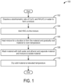
- a flowchart of an example of a hydrothermal method for synthesizing CuV 2 O 6 for use in a magnesium-ion battery is shown in FIG. 1 and XRD characterization of the resulting material is shown in FIG. 2 .
- FIG. 3 A flowchart of an example of method for incorporation the CuV 2 O 6 into a cathode and assembly into a magnesium-ion battery is shown in FIG 3 .
- CuV 2 O 6 delivers a reversible capacity of 100 mAh/g at an average voltage of 2.1 V in a Mg cell, resulting in a high energy density of 210 Wh/kg as illustrated in charging and discharging curves shown in FIG. 4 .
- a SEM-EDS analysis confirms that the magnesium content change during a cycling process corresponds to approximately 0.5 magnesium per formula unit. Further characterization of the charged and discharged Cu 2 V 2 O 6 by XRD, XAS, and TEM is shown in FIGS. 5-9 . Additionally, CuV 2 O 6 exhibits sufficient structural stability during a cycling process as confirmed by negligible volume change during a charge/discharge process. The proposed chemical changes in the CuV 2 O 6 during discharging is further investigated by calculation as illustrated in FIG. 10 .
- CuV 2 O 6 was also identified as a promising Mg cathode candidate through a computational screening methodology.
- the following properties were calculated with density functional theory (DFT) calculations through this screening methodology. All DFT calculations were performed with the Vienna Ab initio Software Package (VASP).
- PBE Perdew-Burke-Ernzerhof
- GGA generalized-gradient approximation
- PAW projector augmented
- a plane-wave cutoff energy was set to 520 eV, and a gamma k-point mesh with a minimal density of 1000 per reciprocal atom was used to sample a Brillouin zone.
- Spin polarization was included in the DFT calculation.
- Structural relaxations were performed for 3 ⁇ 2 ⁇ 2 supercells that contain 12 formula units with forces converging to within 0.02 eV/A°.
- FIG. 1 illustrates a method 100 for synthesizing pure phase CuV 2 O 6 via a hydrothermal synthesis method.
- the method 100 includes dissolving a stoichiometric ratio of CuCl 2 and NH 4 VO 3 in water to form a mixture.
- the water may be deionized water.
- 0.06 M CuCl 2 and 0.12 M NH 4 VO 3 were dissolved in deionized water in a stoichiometric proportion and mixed together with continuous stirring to ensure uniformity of the mixture.
- the stoichiometric proportion may provide the stoichiometry for forming CuV 2 O 6 .
- the stoichiometric ratio may be 1 mole of copper (Cu) for every 2 moles of vanadium (V).
- the method 100 includes adding HNO 3 to the mixture. Adding may include mixing a solution of HNO 3 into the mixture with continuous stirring. A 0.01 M solution of HNO 3 is added to the mixture by continuous stirring, such that HNO 3 comprises approximately 1% by volume of the total volume of the mixture.
- the method 100 includes heating the mixture for a duration to form the material and gradually cooling the material to room temperature.
- Heating may include heating to an elevated temperature to cause a reaction between the CuCl 2 and NH 4 VO 3 .
- heating may include heating to 220°C.
- the duration may be long enough for the reaction to go to completion.
- the duration may be 24 hours.
- the mixture may be placed in a Teflon container in an autoclave where the mixture is heated to 220° C for 24 hours to facilitate the hydrothermal reaction to synthesize the material (e.g.,CuV 2 O 6 ). After 24 hours, the material is gradually cooled to room temperature.
- the material may be cooled by leaving at room temperature until the temperature of the material equilibrates.
- the method includes washing the material with both water and ethanol and separating the material and the mixture to isolate a solid material.
- the wash water may be deionized water.
- a mixture including the deionized water, ethanol, and CuV 2 O 6 (e.g., the material) is formed.
- the material and the mixture may be separated to isolate the material. Separation may include separating by a solid/liquid separation technique. For example, to isolate the solid CuV 2 O 6 , the mixture may be centrifuged to collect the solid CuV 2 O 6 .
- the method 100 includes drying solid material at elevated temperature.
- the elevated temperature may be higher than room temperature to expedite the drying process but not high enough to cause further reactions of the material.
- the elevated drying temperature may be 70°C.
- the solid material is dried at 70° C overnight. Once dried, solid pure phase CuV 2 O 6 is used to fabricate the magnesium battery. The method 100 then ends.
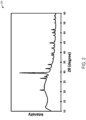
- FIG. 2 An XRD pattern 200 is shown in FIG. 2 .
- the XRD pattern 200 confirms that the hydrothermal process of FIG. 1 synthesized high purity CuV 2 O 6 .
- Magnesium-ion battery 1200 may include a cathode 1202 electrically coupled via a load or charger 1204 to an anode 1206.
- An electrolyte including magnesium ions 1208 may be in fluid contact with both the anode and cathode.
- the cathode may include electroactive material in addition to conductive additive and binder.
- the electroactive material may be CuV 2 O 6 .
- the conductive additive may be carbon.
- the binder may be PTFE.
- magnesium ions 1208 of the electrolyte may be provided by magnesium salts, such as but not limited to bis(trifluoromethanesulfonimide) (Mg(TFSI) 2 ) salts.
- the electrolyte may further include a solvent and one or more additives.
- the solvent of the electrolyte may be 1,1,2,2-tetrafluoroethyl-2,2,3,3,-tetrafluoropropyl ether (TTE).
- TTE 1,1,2,2-tetrafluoroethyl-2,2,3,3,-tetrafluoropropyl ether
- the additive may be diglyme.
- the magnesium ions When charging, the magnesium ions may travel in the direction indicated by arrow 1210 and may be removed from the cathode and insert and/or intercalate into the anode.
- discharging ions When discharging ions may travel in the direction indicated by arrow 1212 and may be removed from the anode and insert into the cathode. Insertion of the magnesium ions into the CuV 2 O 6 electroactive material of the cathode may occur via displacement of Cu 2+ into Cu 0 by the Mg 2+ ions as described further below.
- FIG. 3 shows a method 300 for fabricating a 2-electrode coin cell from a material such as the CuV 2 O 6 synthesized via method 100 described above.
- the 2-electrode coin cell may be an example of a magnesium-ion battery such as magnesium-ion battery 1200 of FIG. 12 .
- the method 300 includes transferring CuV 2 O 6 and conductive carbon into ball mill jars and mixing CuV 2 O 6 and conductive carbon together to form a cathode mixture. More specifically, 140 mg CuV 2 O 6 powder and 40 mg of conductive carbon were transferred to the ball mill jars under an argon atmosphere. The CuV 2 O 6 powder and conductive carbon were mixed with a planetary ball milling for a duration of 3 hours, the planetary ball milling being performed at a rotation speed of 300 rpm.
- the method 300 includes transferring the mixture to a glovebox and adding polytetrafluoroethylene (PTFE) to the cathode mixture.
- the mixture may include a binder.
- the binder may be a PTFE binder.
- additional mixing of the mixture was performed in the glovebox.
- adding may include mixing the PTFE with the cathode mixture with a mortar and pestle for an additional 30 minutes.
- the method 300 includes casting the cathode mixture to obtain a homogeneous cathode film. Casting may include a process to evenly distribute the cathode mixture on a substrate, such as a current collector.
- casting may include performing a rolling process on the cathode mixture to obtain a homogenous cathode film.
- the rolling process may be performed several times (e.g., 8-10 times) on a stainless steel plate to ensure full polymerization of the binder (e.g., PTFE) and ensure homogenous distribution of all components in the mixture.
- the binder e.g., PTFE
- method 300 includes assembling the magnesium ion-battery. Assembling may include constructing the magnesium-ion battery to include a cathode, an anode, and an electrolyte. In one example, assembling may include, at 308, obtaining circular samples of the homogenous cathode film and continuing the rolling process until a desired sample weight is achieved. The circular samples may be obtained by punching out circular samples with a 1 cm 2 surface area from the homogenous film. The rolling process continues for each of the circular samples to reduce thickness of the circular sample and increase the surface area of the sample. Afterwards, the circular samples may be punched again to obtain circular samples with a 1 cm 2 surface area.
- the rolling and punching process may continue iteratively until the circular sample weighs 3 mg and has the appropriate surface area (e.g., 1 cm 2 ).
- Assembling may further include, for example, at 310, inserting the circular sample of the cathode film into a 2-electrode coin cell with electrolyte and testing the electrochemical performance.
- the electrolyte may be a 0.5M Mg(TFSI) 2 / 1M diglyme/ TTE solution and the anode may include activated carbon.
- the electrochemical tests were performed for CuV 2 O 6 as Mg cathodes were performed using 0.5M Mg(TFSI) 2 / 1M diglyme/ TTE solution as an electrolyte and activated carbon as the anode.
- Testing may include charging and discharging the magnesium-ion battery. As discussed below, discharging may cause Mg 2+ to displace Cu 2+ from the CuV 2 O 6 cathode material. The method 300 then ends. The charge/discharge curves obtained when testing the electrochemical performance are shown below in FIG. 4 .
- FIG. 4 shows charge and discharge curves 400 for the first three cycles.
- a first plot 402 corresponds to a first charging and a second plot 404 corresponds to a first discharging.
- a third plot 406 corresponds to a second charging and a fourth plot 408 corresponds to a second discharging.
- a fifth plot 410 corresponds to a third charging and a sixth plot 412 corresponds to third discharging.
- the charge and discharge curves 400 show a reversible capacity of 100 mAh/g at a rate of 2 mA/g.
- FIG. 5 shows ex-situ XRD patterns 500 of CuV 2 O 6 samples in pristine, discharged, and charged conditions.
- the CuV 2 O 6 samples were prepared by interrupting the cycling process at certain conditions, such as when discharged and charged.
- the CuV 2 O 6 film was removed from the coin cell placed in the argon-filled glovebox at these conditions and washed multiple times with diglyme solvent to remove residual matter.
- a first plot 502 corresponds to the pristine CuV 2 O 6 film.
- a second plot 504 corresponds to the discharged CuV 2 O 6 film.
- a third plot 506 corresponds to the charged CuV 2 O 6 film.
- the peak shift of CuV 2 O 6 between the pristine phase, the discharge phase, and the charge phase is relatively small, indicating that small changes in volume occur during the cycling process. In turn, the small volume changes confirm sufficient structural reversibility of CuV 2 O 6 as the magnesium cathode during the cycling process.
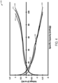
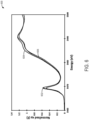
- a first X-ray Absorption Spectroscopy (XAS) spectra 600 and a second XAS spectra 700 are shown in FIGS. 6 and 7 .
- X-ray Absorption Spectroscopy (XAS) experiments were performed for pristine, charged, and re-charged CuV 2 O 6 film samples to investigate redox behavior of CuV 2 O 6 during the electrochemical cycling process in Mg-ion batteries.
- the first XAS spectra 600 is a Vanadium K-edge XAS spectra.
- a first plot 602 corresponds to the pristine CuV 2 O 6 film
- a second plot 604 corresponds to a discharged CuV 2 O 6 film
- a third plot 606 corresponds to a charged (e.g., recharged) CuV 2 O 6 film.
- the first XAS spectra 600 does not show peak shifting between the pristine, charged, and recharged CuV 2 O 6 film samples. The absence of peak shifting indicates that the oxidation state of Vanadium remains at 5+ during the cycling process.
- the second XAS spectra 700 is a Copper K-edge XAS spectra.
- a first plot 702 corresponds to the pristine CuV 2 O 6 film.
- a second plot 704 corresponds to the discharged CuV 2 O 6 film.
- a third plot 706 corresponds to the charged (e.g., re-charged) CuV 2 O 6 film.
- the second XAS spectra 700 suggest that during magnesium cycling, a reversible redox reaction serves as a governing mechanism of CuV 2 O 6 as a cathode material in Magnesium-ion batteries.
- the reversible redox reaction occurs wherein Cu 2+ / Cu 1+ is reduced to Cu 1+ / Cu 0 and Cu 1+ / Cu 0 is oxidized to Cu 2+ /Cu 1+ .
- the copper e.g., Cu 2+ / Cu 1+
- the observed capacity e.g. 100 mAh/g.
- An inset graph 750 shows reference Cu K-edge XAS spectra for copper in different matrixes and oxidation states.
- a first plot 752 corresponds to Cu 2+ :Glycine.
- a second plot 754 corresponds to Cu 2+ in CuCl 2 .
- a third plot 756 corresponds to Cu 2+ in CuO.
- a fourth plot 758 corresponds to Cu 1+ in Cu 2 O.
- a fifth plot 760 corresponds Cu 0 in a copper foil. Points A, B, C, D, and E along the spectra highlight identifying features of the XAS spectra. Comparison of the features of graph 750 to those shown in graph 700 may help confirm the analysis as to the changes in copper oxidation state occurring as the CuV 2 O 6 charges and discharges.
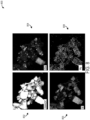
- FIG. 8 shows Transmission Electron Microscope (TEM)/Energy Dispersive X-ray Spectroscopy (EDS) maps 800 of CuV 2 O 6 in a discharged condition and FIG. 9 shows high magnification TEM/EDS Cu maps 900 of the discharged CuV 2 O 6
- Image 802 shows a high-angle annular dark field (HAADF) image of the discharged CuV 2 O 6 .
- Image 804 shows the image 802 with contrast adjusted according to EDS intensity of Cu. Bright areas of image 804 correspond to areas rich in Cu.
- image 806 corresponds to image 802 with contrast adjusted according to EDS intensity of V. Bright areas of image 806 correspond to areas rich in V.
- a fourth image 808 corresponds to image 802 with contrast adjusted according to EDS intensity of Mg.
- Bright areas of image 808 correspond to areas rich in Mg.
- Image 902 of FIG. 9 shows a portion of the discharged CuV 2 O 6 in a higher resolution than image 802 of FIG. 8 .
- Image 904 shows the image 902 with contrast adjusted according to EDS intensity of Cu.
- Bright areas of 904 correspond to areas rich in Cu.
- DFT Density Function Theory
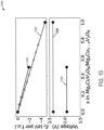
- FIG. 10 shows a comparison 1000 between the formation energy and the voltage of the magnesiation process in CuV 2 O 6 for each of the intercalation reaction and the displacement reaction.
- Plots 1002 and 1004 correspond to the intercalation reaction and plots 1006 and 1008 correspond to the displacement reaction.
- the comparison 1000 shows a calculated voltage for the displacement reaction is 2.4 V, which is about 0.5 V higher than a calculated voltage for the intercalation reaction. Additionally, for the same Mg concentrations, a formation energy of the displacement reaction is lower than a formation energy of the intercalation reaction.
- a lower formation energy for the displacement reaction indicates that the magnesiation of CuV 2 O 6 via the displacement reaction is more thermodynamically favorable than via the intercalation reaction, which is consistent with electrochemical experiments that determined that Cu nanoprecipitates were formed after the discharge cycle.
- the presence of the Cu nanoprecipitates formed via the displacement reaction suggest that the displacement reaction is more favorable than the intercalation reaction which does not produce Cu nanoprecipitates.
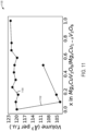
- FIG. 11 illustrates volume changes 1100 observed during the magnesiation process of CuV 2 O 6 in each of the intercalation reaction and the displacement reaction.
- Plot 1102 corresponds to the intercalation reaction
- plot 1104 corresponds to the displacement reaction.
- the volume changes 1100 for each of the intercalation reaction and the displacement reaction show a relationship between volume and different Mg concentrations.
- a larger volume change of approximately 15% is associated with the intercalation reaction.
- the larger volume change makes magnesiation of CuV 2 O 6 with the intercalation reaction undesirable for magnesium-ion batteries due to the insufficient structural stability of CuV 2 O 6 .
- magnesiation of CuV 2 O 6 with the displacement reaction yields adequate structural stability of CuV 2 O 6 .
- the technical effect of the methods described herein is to produce a magnesium-ion battery including CuV 2 O 6 as a high performing cathode active material.
- the magnesium-ion battery including CuV 2 O 6 as the cathode active material results in a high (e.g., 100 mAh/g) reversible energy capacity.
- the high voltage (e.g., 2.1V vs Mg) provided by the CuV 2 O 6 cathode active material results in a high energy density of 210 Wh/kg.
- the CuV 2 O 6 cathode active material provides good structural stability for the magnesium-ion battery due to a negligible volume change of the CuV 2 O 6 cathode active material during the charge/discharge process.
- the disclosure also provides support for a magnesium-ion battery, comprising: an anode, a cathode, and an electrolyte in fluid contact with the anode and cathode, wherein the cathode is comprised of CuV 2 O 6 and the electrolyte includes magnesium ions.
- the anode is activated carbon.
- the cathode further comprises a PTFE binder.
- the cathode wherein the magnesium ions are provided by magnesium bis(trifluoromethanesulfonimide).
- the electrolyte includes 1,1,2,2-tetrafluoroethyl-2,2,3,3,-tetrafluoropropyl ether (TTE).
- TTE 1,1,2,2-tetrafluoroethyl-2,2,3,3,-tetrafluoropropyl ether
- a discharged CuV 2 O 6 includes copper nanoprecipitates.
- the electrolyte further includes diglyme.
- the cathode further includes conductive carbon.
- the disclosure also provides support for a method of producing a magnesium-ion battery including a cathode comprised of CuV 2 O 6 , comprising: casting a cathode mixture including CuV 2 O 6 , conductive carbon, and a binder to obtain a cathode film, and assembling the magnesium-ion battery, the magnesium-ion battery including the cathode film, an anode, and an electrolyte.
- the method further comprises: mixing the CuV 2 O 6 and conductive carbon by ball milling.
- the method further comprises: charging and discharging the magnesium-ion battery, wherein discharging the magnesium-ion battery causes Mg 2+ to displace Cu 2+ from the CuV 2 O 6 .
- the method further comprises: synthesizing the CuV 2 O 6 via hydrothermal synthesis.
- the hydrothermal synthesis includes dissolving a stoichiometric ratio of CuCl 2 and NH 4 VO 3 in water to form a mixture.
- the hydrothermal synthesis includes adding HNO 3 to the mixture. In a sixth example of the method, optionally including one or more or each of the first through fifth examples, the hydrothermal synthesis includes heating the mixture to 220°C.
- Rechargeable multivalent-ion batteries are attractive alternatives to Li-ion batteries to mitigate their issues with metal resources and metal anodes.
- many ongoing challenges remain regarding their practical use due to the low solid-state mobility of multivalent ions.
- CuV 2 O 6 as a Mg cathode.
Landscapes
- Chemical & Material Sciences (AREA)
- General Chemical & Material Sciences (AREA)
- Chemical Kinetics & Catalysis (AREA)
- Electrochemistry (AREA)
- Engineering & Computer Science (AREA)
- Manufacturing & Machinery (AREA)
- Inorganic Chemistry (AREA)
- Composite Materials (AREA)
- General Physics & Mathematics (AREA)
- Condensed Matter Physics & Semiconductors (AREA)
- Physics & Mathematics (AREA)
- Materials Engineering (AREA)
- Battery Electrode And Active Subsutance (AREA)
Abstract
Systems and methods are provided for a magnesium-ion battery (1200). The magnesium-ion battery (1200) includes an anode (1206), a cathode (1202), and an electrolyte in fluid contact with the anode (1206) and cathode (1202). The cathode includes CuV2O6 and the electrolyte includes magnesium ions (1208).
Description
- The present application claims priority to
U.S. Provisional Application No. 63/612,771 entitled "MGCUV2O6 AS CATHODE MATERIALS FOR MAGNESIUM ION BATTERIES", filed on December 20, 2023 - The present description pertains generally to cathode materials for magnesium ion batteries, which can potentially be used as energy storage for applications including electric vehicles, grid-level energy storage, and portable electronics.
- In the last decades, Li-ion batteries (LIBs) have undergone significant progress and played a major role in revolutionary advances in many technologies, including energy-dense portable devices and electric vehicles by providing high energy and power. The remarkable growth of Li-ion batteries is now hampered by resource concerns regarding high quality Li and redox-active transition metals including Co and Ni. Therefore, increasing research investment is being placed in the development of alternative battery systems. Multivalent (Mg, Ca, Al, and Zn) systems have been extensively studied for many years due to their potential for high volumetric capacity enabled by the metal anode, potential lower cost, and higher availability of electroactive components (Li-, Co-, and Ni-free) compared to those of LIBs. Despite these numerous advantages, several challenges remain concerning the implementation of multivalent-ion batteries. One such challenge is the poor diffusion kinetics of multivalent ions in solid phases at room temperature, thereby necessitating the discovery of new material structures and chemistries that promote the high mobility of multivalent ions.
- Several research groups have introduced promising cathode candidates for Mg-ion batteries. Some of these compounds, especially the sulfide- and selenide-based cathodes, can provide specific capacities over 100 mAh/g (Mo6S8, Ti2S4, etc.); however, their low working voltage limits the energy content challenges. Therefore, the exploration of new compounds that reversibly store Mg at a high voltage, and with a high capacity is demanded.
- The inventors have recognized the above listed challenges and herein identified materials and method to at least partially solve the challenges. In one example, a magnesium-ion battery, comprising: an anode; a cathode; and an electrolyte in fluid contact with the anode a cathode, wherein the cathode is comprised of CuV2O6 and the electrolyte includes magnesium ions. Additionally, a method of producing a magnesium-ion battery including a cathode comprising coating a cathode mixture including CuV2O6, conductive carbon, and a binder to obtain a cathode film; and assembling the magnesium-ion battery including the cathode film, an anode, and an electrolyte. In this study, CuV2O6 is identified as a material of interest using a previously reported high-throughput computation screening method from the Materials Project Database and its properties experimentally evaluated as a cathode material for Mg-ion batteries. The CuV2O6 cathode may provide a reversible specific capacity of 100 mAh/g with an average voltage of 2.1 V vs. Mg2+/Mg, resulting in a specific energy of 210 Wh/kg, effectively doubling that of the well-known Chevrel (Mo6S8) phase.
- It should be understood that the summary above is provided to introduce in simplified form a selection of concepts that are further described in the detailed description. It is not meant to identify key or essential features of the claimed subject matter, the scope of which is defined uniquely by the claims that follow the detailed description. Furthermore, the claimed subject matter is not limited to implementations that solve any disadvantages noted above or in any part of this disclosure.
- The present disclosure will be better understood from reading the following description of non-limiting embodiments, with reference to the attached drawings, wherein below:
-
FIG. 1 illustrates a flow diagram of an example process for synthesizing pure phase CuV2O6 with a hydrothermal method; -
FIG. 2 illustrates an example of an XRD pattern of pure phase CuV2O6 synthesized via the hydrothermal method; -
FIG. 3 illustrates a flow diagram describing a process for fabricating a 2-electrode coin cell. -
FIG. 4 illustrates an example of an electrochemical cycling data of hydrothermally synthesized CuV2O6 in a cell with activated carbon anode and 0.5M Mg(TFSI)2 / 1M Diglyme / TTE electrolyte; -
FIG. 5 illustrates examples of XRD patterns of CuV2O6 in pristine, discharged, and charged conditions; -
FIG. 6 illustrates an example of Vanadium K-edge XAS spectra of pristine, discharged, and re-charged CuV2O6; -
FIG. 7 illustrates an example of Copper K-edge XAS spectra of pristine, discharged, and re-charged CuV2O6 -
FIG. 8 illustrates TEM/EDS maps of CuV2O6 in a discharged condition; -
FIG. 9 illustrates high magnification TEM/EDS maps of CuV2O6 in a discharged condition; -
FIG. 10 illustrates an example comparison of formation energy and voltage of a magnesiation process of CuV2O6 for an intercalation reaction and a displacement reaction as predicted from DFT calculations; and -
FIG. 11 illustrate an example volume change during a magnesiation process of CuV2O6 for an intercalation reaction and a displacement reaction as predicted from DFT calculations. -
FIG. 12 illustrates an example of a magnesium-ion battery including a cathode comprised of CuV2O6. - The following description relates to a merely for convenience and brevity and should not be construed as an inflexible limitation on the scope of any embodiments.
- Magnesium-ion batteries are considered a promising alternative to traditional lithium-ion batteries due to their theoretical high energy density, low cost and high availability. An illustration of a magnesium-ion battery is shown in
FIG. 12 . A significant challenge for Mg-ion batteries recognized by the inventors is the lack of high-performance cathode materials. Therefore, the development of new cathode materials that can improve the performance of Mg-ion batteries is demanded to unlock the full potential of it for a wide range of application such as electric vehicles and grid-scale energy storage. - CuV2O6 has been previously studied in the literature with an emphasis on their electrochemical properties as lithium and zinc cathodes. Surprisingly, CuV2O6 may also be used as a cathode material for magnesium ion batteries. A flowchart of an example of a hydrothermal method for synthesizing CuV2O6 for use in a magnesium-ion battery is shown in
FIG. 1 and XRD characterization of the resulting material is shown inFIG. 2 . A flowchart of an example of method for incorporation the CuV2O6 into a cathode and assembly into a magnesium-ion battery is shown inFIG 3 . As the cathode material, CuV2O6 delivers a reversible capacity of 100 mAh/g at an average voltage of 2.1 V in a Mg cell, resulting in a high energy density of 210 Wh/kg as illustrated in charging and discharging curves shown inFIG. 4 . A SEM-EDS analysis confirms that the magnesium content change during a cycling process corresponds to approximately 0.5 magnesium per formula unit. Further characterization of the charged and discharged Cu2V2O6 by XRD, XAS, and TEM is shown inFIGS. 5-9 . Additionally, CuV2O6 exhibits sufficient structural stability during a cycling process as confirmed by negligible volume change during a charge/discharge process. The proposed chemical changes in the CuV2O6 during discharging is further investigated by calculation as illustrated inFIG. 10 . - CuV2O6 was also identified as a promising Mg cathode candidate through a computational screening methodology. The following properties were calculated with density functional theory (DFT) calculations through this screening methodology. All DFT calculations were performed with the Vienna Ab initio Software Package (VASP). The DFT calculation details for the magnesiation process of CuV2O6 are as follows. Electron-ion interactions were described with the Perdew-Burke-Ernzerhof (PBE) generalized-gradient approximation (GGA) function in conjunction with projector augmented (PAW) pseudopotentials. A Hubbard U correction of Uv = 3.25 eV was used to account for strong electron-electron interactions. A plane-wave cutoff energy was set to 520 eV, and a gamma k-point mesh with a minimal density of 1000 per reciprocal atom was used to sample a Brillouin zone. Spin polarization was included in the DFT calculation. Structural relaxations were performed for 3 × 2 × 2 supercells that contain 12 formula units with forces converging to within 0.02 eV/A°.
-
FIG. 1 illustrates amethod 100 for synthesizing pure phase CuV2O6 via a hydrothermal synthesis method. At 102, themethod 100 includes dissolving a stoichiometric ratio of CuCl2 and NH4VO3 in water to form a mixture. In some examples, the water may be deionized water. In particular, 0.06 M CuCl2 and 0.12 M NH4VO3 were dissolved in deionized water in a stoichiometric proportion and mixed together with continuous stirring to ensure uniformity of the mixture. The stoichiometric proportion may provide the stoichiometry for forming CuV2O6. As such, the stoichiometric ratio may be 1 mole of copper (Cu) for every 2 moles of vanadium (V). - At 104, the
method 100 includes adding HNO3 to the mixture. Adding may include mixing a solution of HNO3 into the mixture with continuous stirring. A 0.01 M solution of HNO3 is added to the mixture by continuous stirring, such that HNO3 comprises approximately 1% by volume of the total volume of the mixture. - At 106, the
method 100 includes heating the mixture for a duration to form the material and gradually cooling the material to room temperature. Heating may include heating to an elevated temperature to cause a reaction between the CuCl2 and NH4VO3. As one example, heating may include heating to 220°C. The duration may be long enough for the reaction to go to completion. As one example, the duration may be 24 hours. For example, the mixture may be placed in a Teflon container in an autoclave where the mixture is heated to 220° C for 24 hours to facilitate the hydrothermal reaction to synthesize the material (e.g.,CuV2O6). After 24 hours, the material is gradually cooled to room temperature. For example, the material may be cooled by leaving at room temperature until the temperature of the material equilibrates. - At 108, the method includes washing the material with both water and ethanol and separating the material and the mixture to isolate a solid material. In some examples the wash water may be deionized water. After washing the material with deionized water and ethanol to remove impurities, a mixture including the deionized water, ethanol, and CuV2O6 (e.g., the material) is formed. The material and the mixture may be separated to isolate the material. Separation may include separating by a solid/liquid separation technique. For example, to isolate the solid CuV2O6, the mixture may be centrifuged to collect the solid CuV2O6. At 110, the
method 100 includes drying solid material at elevated temperature. The elevated temperature may be higher than room temperature to expedite the drying process but not high enough to cause further reactions of the material. For example, the elevated drying temperature may be 70°C. As one example, to remove any additional deionized water adhering to and/or absorbed by the solid material, the solid material is dried at 70° C overnight. Once dried, solid pure phase CuV2O6 is used to fabricate the magnesium battery. Themethod 100 then ends. - An XRD pattern 200 is shown in
FIG. 2 . The XRD pattern 200 confirms that the hydrothermal process ofFIG. 1 synthesized high purity CuV2O6. - Turning briefly to
FIG. 12 , a simplified diagram of a magnesium-ion battery 1200 is shown. Magnesium-ion battery 1200 may include acathode 1202 electrically coupled via a load orcharger 1204 to ananode 1206. An electrolyte includingmagnesium ions 1208 may be in fluid contact with both the anode and cathode. The cathode may include electroactive material in addition to conductive additive and binder. In one example, the electroactive material may be CuV2O6. In one example, the conductive additive may be carbon. As one example, the binder may be PTFE. In one example,magnesium ions 1208 of the electrolyte may be provided by magnesium salts, such as but not limited to bis(trifluoromethanesulfonimide) (Mg(TFSI)2) salts. The electrolyte may further include a solvent and one or more additives. For example, the solvent of the electrolyte may be 1,1,2,2-tetrafluoroethyl-2,2,3,3,-tetrafluoropropyl ether (TTE). In some examples, the additive may be diglyme. When charging, the magnesium ions may travel in the direction indicated byarrow 1210 and may be removed from the cathode and insert and/or intercalate into the anode. When discharging ions may travel in the direction indicated byarrow 1212 and may be removed from the anode and insert into the cathode. Insertion of the magnesium ions into the CuV2O6 electroactive material of the cathode may occur via displacement of Cu2+ into Cu0 by the Mg2+ ions as described further below. -
FIG. 3 shows amethod 300 for fabricating a 2-electrode coin cell from a material such as the CuV2O6 synthesized viamethod 100 described above. The 2-electrode coin cell may be an example of a magnesium-ion battery such as magnesium-ion battery 1200 ofFIG. 12 . At 302, themethod 300 includes transferring CuV2O6 and conductive carbon into ball mill jars and mixing CuV2O6 and conductive carbon together to form a cathode mixture. More specifically, 140 mg CuV2O6 powder and 40 mg of conductive carbon were transferred to the ball mill jars under an argon atmosphere. The CuV2O6 powder and conductive carbon were mixed with a planetary ball milling for a duration of 3 hours, the planetary ball milling being performed at a rotation speed of 300 rpm. - At 304, the
method 300 includes transferring the mixture to a glovebox and adding polytetrafluoroethylene (PTFE) to the cathode mixture. In this way, the mixture may include a binder. The binder may be a PTFE binder. After 20 mg of PTFE was added to the mixture, additional mixing of the mixture was performed in the glovebox. For example, adding may include mixing the PTFE with the cathode mixture with a mortar and pestle for an additional 30 minutes. At 306, themethod 300 includes casting the cathode mixture to obtain a homogeneous cathode film. Casting may include a process to evenly distribute the cathode mixture on a substrate, such as a current collector. As one example, casting may include performing a rolling process on the cathode mixture to obtain a homogenous cathode film. The rolling process may be performed several times (e.g., 8-10 times) on a stainless steel plate to ensure full polymerization of the binder (e.g., PTFE) and ensure homogenous distribution of all components in the mixture. - At 307,
method 300 includes assembling the magnesium ion-battery. Assembling may include constructing the magnesium-ion battery to include a cathode, an anode, and an electrolyte. In one example, assembling may include, at 308, obtaining circular samples of the homogenous cathode film and continuing the rolling process until a desired sample weight is achieved. The circular samples may be obtained by punching out circular samples with a 1 cm2 surface area from the homogenous film. The rolling process continues for each of the circular samples to reduce thickness of the circular sample and increase the surface area of the sample. Afterwards, the circular samples may be punched again to obtain circular samples with a 1 cm2 surface area. The rolling and punching process may continue iteratively until the circular sample weighs 3 mg and has the appropriate surface area (e.g., 1 cm2). Assembling may further include, for example, at 310, inserting the circular sample of the cathode film into a 2-electrode coin cell with electrolyte and testing the electrochemical performance. The electrolyte may be a 0.5M Mg(TFSI)2 / 1M diglyme/ TTE solution and the anode may include activated carbon. The electrochemical tests were performed for CuV2O6 as Mg cathodes were performed using 0.5M Mg(TFSI)2 / 1M diglyme/ TTE solution as an electrolyte and activated carbon as the anode. Testing may include charging and discharging the magnesium-ion battery. As discussed below, discharging may cause Mg2+ to displace Cu2+ from the CuV2O6 cathode material. Themethod 300 then ends. The charge/discharge curves obtained when testing the electrochemical performance are shown below inFIG. 4 . -
FIG. 4 shows charge and dischargecurves 400 for the first three cycles. Afirst plot 402 corresponds to a first charging and asecond plot 404 corresponds to a first discharging. Athird plot 406 corresponds to a second charging and afourth plot 408 corresponds to a second discharging. Afifth plot 410 corresponds to a third charging and asixth plot 412 corresponds to third discharging. The charge and dischargecurves 400 show a reversible capacity of 100 mAh/g at a rate of 2 mA/g. -
FIG. 5 showsex-situ XRD patterns 500 of CuV2O6 samples in pristine, discharged, and charged conditions. For an ex-situ analysis, the CuV2O6 samples were prepared by interrupting the cycling process at certain conditions, such as when discharged and charged. The CuV2O6 film was removed from the coin cell placed in the argon-filled glovebox at these conditions and washed multiple times with diglyme solvent to remove residual matter. - XRD is performed on the ex-situ CuV2O6 film when the CuV2O6 film is in a pristine phase, a discharge phase, and a charge phase and the
XRD patterns 500 are the results of the analysis. Afirst plot 502 corresponds to the pristine CuV2O6 film. Asecond plot 504 corresponds to the discharged CuV2O6 film. Athird plot 506 corresponds to the charged CuV2O6 film. As shown inFIG. 5 , the peak shift of CuV2O6 between the pristine phase, the discharge phase, and the charge phase is relatively small, indicating that small changes in volume occur during the cycling process. In turn, the small volume changes confirm sufficient structural reversibility of CuV2O6 as the magnesium cathode during the cycling process. - A first X-ray Absorption Spectroscopy (XAS)
spectra 600 and asecond XAS spectra 700 are shown inFIGS. 6 and7 . X-ray Absorption Spectroscopy (XAS) experiments were performed for pristine, charged, and re-charged CuV2O6 film samples to investigate redox behavior of CuV2O6 during the electrochemical cycling process in Mg-ion batteries. Turning toFIG. 6 , thefirst XAS spectra 600 is a Vanadium K-edge XAS spectra. Afirst plot 602 corresponds to the pristine CuV2O6 film, asecond plot 604 corresponds to a discharged CuV2O6 film and athird plot 606 corresponds to a charged (e.g., recharged) CuV2O6 film. Thefirst XAS spectra 600 does not show peak shifting between the pristine, charged, and recharged CuV2O6 film samples. The absence of peak shifting indicates that the oxidation state of Vanadium remains at 5+ during the cycling process. - Returning to
FIG. 7 , thesecond XAS spectra 700 is a Copper K-edge XAS spectra. Afirst plot 702 corresponds to the pristine CuV2O6 film. Asecond plot 704 corresponds to the discharged CuV2O6 film. Athird plot 706 corresponds to the charged (e.g., re-charged) CuV2O6 film. Thesecond XAS spectra 700 suggest that during magnesium cycling, a reversible redox reaction serves as a governing mechanism of CuV2O6 as a cathode material in Magnesium-ion batteries. In particular, during the charge/discharge cycles, the reversible redox reaction occurs wherein Cu2+/ Cu1+ is reduced to Cu1+/ Cu0 and Cu1+/ Cu0 is oxidized to Cu2+/Cu1+. Approximately, half of the copper (e.g., Cu2+/ Cu1+) in the CuV2O6 film samples was reduced for the observed capacity (e.g., 100 mAh/g). - An
inset graph 750 shows reference Cu K-edge XAS spectra for copper in different matrixes and oxidation states. Afirst plot 752 corresponds to Cu2+:Glycine. Asecond plot 754 corresponds to Cu2+ in CuCl2. Athird plot 756 corresponds to Cu2+ in CuO. Afourth plot 758 corresponds to Cu1+ in Cu2O. Afifth plot 760 corresponds Cu0 in a copper foil. Points A, B, C, D, and E along the spectra highlight identifying features of the XAS spectra. Comparison of the features ofgraph 750 to those shown ingraph 700 may help confirm the analysis as to the changes in copper oxidation state occurring as the CuV2O6 charges and discharges. -
FIG. 8 shows Transmission Electron Microscope (TEM)/Energy Dispersive X-ray Spectroscopy (EDS) maps 800 of CuV2O6 in a discharged condition andFIG. 9 shows high magnification TEM/EDS Cu maps 900 of the discharged CuV2O6 Image 802 shows a high-angle annular dark field (HAADF) image of the discharged CuV2O6. Image 804 shows theimage 802 with contrast adjusted according to EDS intensity of Cu. Bright areas ofimage 804 correspond to areas rich in Cu. Similarlyimage 806 corresponds to image 802 with contrast adjusted according to EDS intensity of V. Bright areas ofimage 806 correspond to areas rich in V. Afourth image 808 corresponds to image 802 with contrast adjusted according to EDS intensity of Mg. Bright areas ofimage 808 correspond to areas rich in Mg.Image 902 ofFIG. 9 shows a portion of the discharged CuV2O6 in a higher resolution thanimage 802 ofFIG. 8 .Image 904 shows theimage 902 with contrast adjusted according to EDS intensity of Cu. Bright areas of 904 correspond to areas rich in Cu. - In this way, the reversible redox reaction that occurs during the magnesium cycling was analyzed. The results of the TEM and EDS analysis shown in
FIGS. 8-9 indicate that copper nanoprecipitates were present in the discharged CuV2O6 sample, suggesting that Cu2+ is reduced to elemental Cu0 to form copper nanoprecipitates during the discharging process. The copper nanoprecipitates may be oxidized back to Cu2+ during the charging process to complete the reversible electrochemical cycle. - As described herein, Density Function Theory (DFT) calculations were performed to investigate the magnesiation process in CuV2O6 as a cathode in a magnesium-ion cell with the simulation parameters described above. In particular, magnesiation of CuV2O6 was analyzed by comparing energetics for both of an intercalation reaction and a displacement reaction between magnesium and CuV2O6. Magnesiation of CuV2O6 by the intercalation reaction is seen below in
Equation 1:
CuV2O6 + xMg → MgxCuV2O6 (1)
- Magnesiation of CuV2O6 by the displacement reaction is seen below in Equation 2:
CuV2O6 + xMg → MgxCu 1 -xV 2 O 6 + xCu (2)
- Both of the intercalation voltage and the displacement voltage were calculated with Equation 3:

-
FIG. 10 shows acomparison 1000 between the formation energy and the voltage of the magnesiation process in CuV2O6 for each of the intercalation reaction and the displacement reaction.Plots plots comparison 1000 shows a calculated voltage for the displacement reaction is 2.4 V, which is about 0.5 V higher than a calculated voltage for the intercalation reaction. Additionally, for the same Mg concentrations, a formation energy of the displacement reaction is lower than a formation energy of the intercalation reaction. A lower formation energy for the displacement reaction indicates that the magnesiation of CuV2O6 via the displacement reaction is more thermodynamically favorable than via the intercalation reaction, which is consistent with electrochemical experiments that determined that Cu nanoprecipitates were formed after the discharge cycle. The presence of the Cu nanoprecipitates formed via the displacement reaction suggest that the displacement reaction is more favorable than the intercalation reaction which does not produce Cu nanoprecipitates. -
FIG. 11 illustratesvolume changes 1100 observed during the magnesiation process of CuV2O6 in each of the intercalation reaction and the displacement reaction.Plot 1102 corresponds to the intercalation reaction andplot 1104 corresponds to the displacement reaction. In particular, thevolume changes 1100 for each of the intercalation reaction and the displacement reaction show a relationship between volume and different Mg concentrations. A larger volume change of approximately 15% is associated with the intercalation reaction. The larger volume change makes magnesiation of CuV2O6 with the intercalation reaction undesirable for magnesium-ion batteries due to the insufficient structural stability of CuV2O6. In contrast, a smaller volume change is observed with magnesiation of CuV2O6 with the displacement reaction, which is consistent with the ex-situ XRD pattern results. As such, magnesiation of CuV2O6 with the displacement reaction yields adequate structural stability of CuV2O6. - The technical effect of the methods described herein is to produce a magnesium-ion battery including CuV2O6 as a high performing cathode active material. The magnesium-ion battery including CuV2O6 as the cathode active material results in a high (e.g., 100 mAh/g) reversible energy capacity. Further, the high voltage (e.g., 2.1V vs Mg) provided by the CuV2O6 cathode active material results in a high energy density of 210 Wh/kg. Additionally, the CuV2O6 cathode active material provides good structural stability for the magnesium-ion battery due to a negligible volume change of the CuV2O6 cathode active material during the charge/discharge process.
- The disclosure also provides support for a magnesium-ion battery, comprising: an anode, a cathode, and an electrolyte in fluid contact with the anode and cathode, wherein the cathode is comprised of CuV2O6 and the electrolyte includes magnesium ions. In a first example of the system, the anode is activated carbon. In a second example of the system, optionally including the first example, the cathode further comprises a PTFE binder. In a third example of the system, optionally including one or both of the first and second examples, the cathode wherein the magnesium ions are provided by magnesium bis(trifluoromethanesulfonimide). In a fourth example of the system, optionally including one or more or each of the first through third examples, the electrolyte includes 1,1,2,2-tetrafluoroethyl-2,2,3,3,-tetrafluoropropyl ether (TTE). In a fifth example of the system, optionally including one or more or each of the first through fourth examples, a discharged CuV2O6 includes copper nanoprecipitates. In a sixth example of the system, optionally including one or more or each of the first through fifth examples, the electrolyte further includes diglyme. In a seventh example of the system, optionally including one or more or each of the first through sixth examples, the cathode further includes conductive carbon.
- The disclosure also provides support for a method of producing a magnesium-ion battery including a cathode comprised of CuV2O6, comprising: casting a cathode mixture including CuV2O6, conductive carbon, and a binder to obtain a cathode film, and assembling the magnesium-ion battery, the magnesium-ion battery including the cathode film, an anode, and an electrolyte. In a first example of the method, the method further comprises: mixing the CuV2O6 and conductive carbon by ball milling. In a second example of the method, optionally including the first example, the method further comprises: charging and discharging the magnesium-ion battery, wherein discharging the magnesium-ion battery causes Mg2+ to displace Cu2+ from the CuV2O6. In a third example of the method, optionally including one or both of the first and second examples, the method further comprises: synthesizing the CuV2O6 via hydrothermal synthesis. In a fourth example of the method, optionally including one or more or each of the first through third examples, the hydrothermal synthesis includes dissolving a stoichiometric ratio of CuCl2 and NH4VO3 in water to form a mixture. In a fifth example of the method, optionally including one or more or each of the first through fourth examples, the hydrothermal synthesis includes adding HNO3 to the mixture. In a sixth example of the method, optionally including one or more or each of the first through fifth examples, the hydrothermal synthesis includes heating the mixture to 220°C.
- The description of a range herein should be considered to have specifically disclosed all the possible subranges as well of any individual numerical values within that range to the tenth of the unit of the lower limit unless the context clearly dictates otherwise. For example, description of a range such as from 1 to 6 should be considered to have specifically disclosed subranges such as from 1 to 3, from 1 to 4, from 1 to 5, from 2 to 4, from 2 to 6, from 3 to 6 etc., as well of any individual values within that range, for example, 1.1,2, 2.3, 5, and 5.9. This applies regardless of the breadth of the range. The upper and lower limits of these intervening ranges may independently be included in the smaller ranges, and are also encompassed within the invention, subject to any specifically excluded limit in the stated range. Where the stated range includes one or both of the limits, ranges excluding either or both of those included limits are also included in the invention, unless the context clearly dictates otherwise.
- The terminology used herein is for the purpose of describing particular embodiments only and is not intended to be limiting of any embodiment. As used herein, the singular forms "a," "an" and "the" are intended to include the plural forms as well, unless the context clearly indicates otherwise. It will be further understood that the terms "comprises" and/or "comprising," when used in this specification, specify the presence of stated features, integers, steps, operations, elements, and/or components, but do not preclude the presence or addition of one or more other features, integers, steps, operations, elements, components, and/or groups thereof. As used herein, the term "and/or" includes any and all combinations of one or more of the associated listed items.
- The previously described versions of the disclosed subject matter have many advantages that were either described or would be apparent to a person of ordinary skill. Even so, these advantages or features are not required in all versions of the disclosed apparatus, systems, or methods.
- Additionally, this written description makes reference to particular features. It is to be understood that the disclosure in this specification includes all possible combinations of those particular features. Where a particular feature is disclosed in the context of a particular aspect or example, that feature can also be used, to the extent possible, in the context of other aspects and examples.
- Also, when reference is made in this application to a method having two or more defined steps or operations, the defined steps or operations can be carried out in any order or simultaneously, unless the context excludes those possibilities.
- Although specific examples of the invention have been illustrated and described for purposes of illustration, it will be understood that various modifications may be made without departing from the spirit and scope of the invention.
- In an aspect of the present disclosure, there is provided:
Rechargeable multivalent-ion batteries are attractive alternatives to Li-ion batteries to mitigate their issues with metal resources and metal anodes. However, many ongoing challenges remain regarding their practical use due to the low solid-state mobility of multivalent ions. In this study, we investigate a promising material identified by high-throughput computational screening and experimental screening, CuV2O6, as a Mg cathode. We evaluate and experimentally prove that CuV2O6 can provide an energy density of >200 Wh/kg, more than twice that of state-of-the-art Chevrel compounds. - In some aspects of the present disclosure, there are provided the following clauses:
- Clause 1: The CuV2O6 is identified as a cathode material for Magnesium ion batteries.
- Clause 2: As experimentally determined, it provides 0.5 Mg inserted every formula unit.
- Clause 3: Electrochemical experiments have shown that this material delivers a reversible capacity of 100 mAh/g at an average voltage of 2.1 V, resulting in a high energy density of 210 Wh/kg.
- Clause 4: It exhibits sufficient structural stability during the charging/discharging process.
- Clause 5: These properties make it a promising candidate for use in next-generation Mg-ion batteries, which have the potential to provide high energy density and low cost compared to existing battery technologies.
Claims (15)
- A magnesium-ion battery (1200), comprising:an anode (1206);a cathode (1202); andan electrolyte in fluid contact with the anode (1206) and cathode (1202), wherein the cathode is comprised of CuV2O6 and the electrolyte includes magnesium ions (1208).
- The magnesium-ion battery of claim 1, wherein the anode is activated carbon.
- The magnesium-ion battery of claim 1 or 2, wherein the cathode further comprises a PTFE binder.
- The magnesium-ion battery of any of claims 1 to 3, wherein the cathode wherein the magnesium ions are provided by magnesium bis(trifluoromethanesulfonimide).
- The magnesium-ion battery of any of claims 1 to 4, wherein the electrolyte includes 1,1,2,2-tetrafluoroethyl-2,2,3,3,-tetrafluoropropyl ether (TTE).
- The magnesium-ion battery of any of claims 1 to 5, wherein a discharged CuV2O6 includes copper nanoprecipitates.
- The magnesium-ion battery of any of claims 1 to 6, wherein the electrolyte further includes diglyme.
- The magnesium-ion battery of any of claims 1 to 7, wherein the cathode further includes conductive carbon.
- A method of producing a magnesium-ion battery including a cathode comprised of CuV2O6, comprising:casting (306) a cathode mixture including CuV2O6, conductive carbon, and a binder to obtain a cathode film; andassembling (307) the magnesium-ion battery, the magnesium-ion battery including the cathode film, an anode, and an electrolyte.
- The method of claim 9, further comprising mixing the CuV2O6 and conductive carbon by ball milling.
- The method of claim 9 or 10, further comprising charging and discharging the magnesium-ion battery, wherein discharging the magnesium-ion battery causes Mg2+ to displace Cu2+ from the CuV2O6.
- The method of claim any of claims 9 to 11, further comprising synthesizing the CuV2O6 via hydrothermal synthesis.
- The method of claim 12, wherein the hydrothermal synthesis includes dissolving a stoichiometric ratio of CuCl2 and NH4VO3 in water to form a mixture.
- The method of claim 13, wherein the hydrothermal synthesis includes adding HNO3 to the mixture.
- The method of claim 14, wherein the hydrothermal synthesis includes heating the mixture to 220°C.
Applications Claiming Priority (1)
| Application Number | Priority Date | Filing Date | Title |
|---|---|---|---|
| US202363612771P | 2023-12-20 | 2023-12-20 |
Publications (1)
| Publication Number | Publication Date |
|---|---|
| EP4576236A1 true EP4576236A1 (en) | 2025-06-25 |
Family
ID=93925191
Family Applications (1)
| Application Number | Title | Priority Date | Filing Date |
|---|---|---|---|
| EP24221072.2A Pending EP4576236A1 (en) | 2023-12-20 | 2024-12-18 | Mgcuv2o6 as cathode materials for magnesium ion batteries |
Country Status (1)
| Country | Link |
|---|---|
| EP (1) | EP4576236A1 (en) |
Citations (2)
| Publication number | Priority date | Publication date | Assignee | Title |
|---|---|---|---|---|
| US20190067743A1 (en) * | 2017-08-24 | 2019-02-28 | Uchicago Argonne, Llc | Halogen-free electrolytes for magnesium batteries |
| KR20210086215A (en) * | 2019-12-31 | 2021-07-08 | 한국전력공사 | Electrolyte and hybrid battery including the same |
-
2024
- 2024-12-18 EP EP24221072.2A patent/EP4576236A1/en active Pending
Patent Citations (2)
| Publication number | Priority date | Publication date | Assignee | Title |
|---|---|---|---|---|
| US20190067743A1 (en) * | 2017-08-24 | 2019-02-28 | Uchicago Argonne, Llc | Halogen-free electrolytes for magnesium batteries |
| KR20210086215A (en) * | 2019-12-31 | 2021-07-08 | 한국전력공사 | Electrolyte and hybrid battery including the same |
Non-Patent Citations (2)
| Title |
|---|
| JIANG XUE ET AL: "Hydrothermal synthesis of new CuVO2 delafossite hexagonal nanoplates", CERAMICS INTERNATIONAL, ELSEVIER, AMSTERDAM, NL, vol. 46, no. 18, 1 August 2020 (2020-08-01), pages 28219 - 28226, XP086322577, ISSN: 0272-8842, [retrieved on 20250425], DOI: 10.1016/J.CERAMINT.2020.07.322 * |
| LIU YUYI ET AL: "Graphene Oxide Wrapped CuV2O6 Nanobelts as High-Capacity and Long-Life Cathode Materials of Aqueous Zinc-Ion Batteries | ACS Nano", ACS NANO, vol. 13, no. 10, 25 September 2019 (2019-09-25), US, pages 12081 - 12089, XP093272822, ISSN: 1936-0851, Retrieved from the Internet <URL:https://pubs.acs.org/doi/10.1021/acsnano.9b06484> [retrieved on 20250425], DOI: 10.1021/acsnano.9b06484 * |
Similar Documents
| Publication | Publication Date | Title |
|---|---|---|
| Shi et al. | Unlocking the potential of P3 structure for practical Sodium-ion batteries by fabricating zero strain framework for Na+ intercalation | |
| Lee et al. | Toward a low-cost high-voltage sodium aqueous rechargeable battery | |
| Yan et al. | An innovation: Dendrite free quinone paired with ZnMn2O4 for zinc ion storage | |
| Leng et al. | Superior electrochemical performance of O3-type NaNi0. 5-xMn0. 3Ti0. 2ZrxO2 cathode material for sodium-ion batteries from Ti and Zr substitution of the transition metals | |
| Lu et al. | Enabling high-performance sodium metal anodes via A sodiophilic structure constructed by hierarchical Sb2MoO6 microspheres | |
| Li et al. | LiNi 1/3 Co 1/3 Mn 1/3 O 2 hollow nano-micro hierarchical microspheres with enhanced performances as cathodes for lithium-ion batteries | |
| Naveen et al. | Highly stable P′ 3-K0. 8CrO2 cathode with limited dimensional changes for potassium ion batteries | |
| Nguyen et al. | Magnesium stannide as a high-capacity anode for magnesium-ion batteries | |
| Nie et al. | Prussian blue analogues: a new class of anode materials for lithium ion batteries | |
| Hou et al. | Hollow opening nanoflowers MoS2-CuS-EG cathodes for high-performance hybrid Mg/Li-ion batteries | |
| Quyen et al. | Carbon coated NaLi0. 2Mn0. 8O2 as a superb cathode material for sodium ion batteries | |
| Pleuksachat et al. | Dynamic phase transition behavior of a LiMn0. 5Fe0. 5PO4 olivine cathode material for lithium-ion batteries revealed through in-situ X-ray techniques | |
| Park et al. | Rechargeable Na/Ni batteries based on the Ni (OH) 2/NiOOH redox couple with high energy density and good cycling performance | |
| Yu et al. | Maximized crystal water content and charge-shielding effect in layered vanadate render superior aqueous zinc-ion battery | |
| Ying et al. | Insight into pseudocapacitive-diffusion mixed kinetics and conversion-alloying hybrid mechanisms of low-cost Zn-Mn perovskite fluorides anodes for powerful Li-ion/dual-ion storage | |
| Wang et al. | Surface engineering with ammonium niobium oxalate: A multifunctional strategy to enhance electrochemical performance and thermal stability of Ni-rich cathode materials at 4.5 V cutoff potential | |
| Benmayza et al. | Electrochemical and thermal studies of bismuth electrodes for magnesium-ion cells | |
| Maeyoshi et al. | Improving cycling stability of vanadium sulfide (VS4) as a Li battery cathode material using a localized high-concentration carbonate-based electrolyte | |
| Huang et al. | Mg-substituted Prussian blue as a low-strain cathode material for aqueous Fe-ion batteries | |
| Zhang et al. | Green and facile synthesis of porous ZnCO3 as a novel anode material for advanced lithium-ion batteries | |
| Soares et al. | Weyl semimetal orthorhombic Td-WTe2 as an electrode material for sodium-and potassium-ion batteries | |
| Jiao et al. | Highly stable anode-free sodium batteries enabled by mechanically deformable nucleation interface | |
| US10177404B2 (en) | Active material for rechargeable battery | |
| Wang et al. | Facile synthesis and electrochemical performance of the nanoscaled FePy anode | |
| Kim et al. | Multifunctional surface modification with Co-free spinel structure on Ni-rich cathode material for improved electrochemical performance |
Legal Events
| Date | Code | Title | Description |
|---|---|---|---|
| PUAI | Public reference made under article 153(3) epc to a published international application that has entered the european phase |
Free format text: ORIGINAL CODE: 0009012 |
|
| STAA | Information on the status of an ep patent application or granted ep patent |
Free format text: STATUS: THE APPLICATION HAS BEEN PUBLISHED |
|
| AK | Designated contracting states |
Kind code of ref document: A1 Designated state(s): AL AT BE BG CH CY CZ DE DK EE ES FI FR GB GR HR HU IE IS IT LI LT LU LV MC ME MK MT NL NO PL PT RO RS SE SI SK SM TR |
|
| STAA | Information on the status of an ep patent application or granted ep patent |
Free format text: STATUS: REQUEST FOR EXAMINATION WAS MADE |
|
| 17P | Request for examination filed |
Effective date: 20251208 |