EP4576050A1 - Apparatus for mounting a display board - Google Patents
Apparatus for mounting a display board Download PDFInfo
- Publication number
- EP4576050A1 EP4576050A1 EP24221457.5A EP24221457A EP4576050A1 EP 4576050 A1 EP4576050 A1 EP 4576050A1 EP 24221457 A EP24221457 A EP 24221457A EP 4576050 A1 EP4576050 A1 EP 4576050A1
- Authority
- EP
- European Patent Office
- Prior art keywords
- base member
- display board
- region
- clamp member
- clamping
- Prior art date
- Legal status (The legal status is an assumption and is not a legal conclusion. Google has not performed a legal analysis and makes no representation as to the accuracy of the status listed.)
- Pending
Links
Images



Classifications
-
- G—PHYSICS
- G09—EDUCATION; CRYPTOGRAPHY; DISPLAY; ADVERTISING; SEALS
- G09F—DISPLAYING; ADVERTISING; SIGNS; LABELS OR NAME-PLATES; SEALS
- G09F19/00—Advertising or display means not otherwise provided for
- G09F19/22—Advertising or display means on roads, walls or similar surfaces, e.g. illuminated
- G09F19/227—Advertising or display means on roads, walls or similar surfaces, e.g. illuminated on windows
-
- G—PHYSICS
- G09—EDUCATION; CRYPTOGRAPHY; DISPLAY; ADVERTISING; SEALS
- G09F—DISPLAYING; ADVERTISING; SIGNS; LABELS OR NAME-PLATES; SEALS
- G09F7/00—Signs, name or number plates, letters, numerals, or symbols; Panels or boards
- G09F7/18—Means for attaching signs, plates, panels, or boards to a supporting structure
-
- G—PHYSICS
- G09—EDUCATION; CRYPTOGRAPHY; DISPLAY; ADVERTISING; SEALS
- G09F—DISPLAYING; ADVERTISING; SIGNS; LABELS OR NAME-PLATES; SEALS
- G09F15/00—Boards, hoardings, pillars, or like structures for notices, placards, posters, or the like
- G09F15/0006—Boards, hoardings, pillars, or like structures for notices, placards, posters, or the like planar structures comprising one or more panels
- G09F15/0018—Boards, hoardings, pillars, or like structures for notices, placards, posters, or the like planar structures comprising one or more panels panel clamping or fastening means
-
- G—PHYSICS
- G09—EDUCATION; CRYPTOGRAPHY; DISPLAY; ADVERTISING; SEALS
- G09F—DISPLAYING; ADVERTISING; SIGNS; LABELS OR NAME-PLATES; SEALS
- G09F7/00—Signs, name or number plates, letters, numerals, or symbols; Panels or boards
- G09F7/18—Means for attaching signs, plates, panels, or boards to a supporting structure
- G09F7/20—Means for attaching signs, plates, panels, or boards to a supporting structure for adjustably mounting
-
- G—PHYSICS
- G09—EDUCATION; CRYPTOGRAPHY; DISPLAY; ADVERTISING; SEALS
- G09F—DISPLAYING; ADVERTISING; SIGNS; LABELS OR NAME-PLATES; SEALS
- G09F7/00—Signs, name or number plates, letters, numerals, or symbols; Panels or boards
- G09F7/18—Means for attaching signs, plates, panels, or boards to a supporting structure
- G09F2007/1847—Brackets to grip the sign board
-
- G—PHYSICS
- G09—EDUCATION; CRYPTOGRAPHY; DISPLAY; ADVERTISING; SEALS
- G09F—DISPLAYING; ADVERTISING; SIGNS; LABELS OR NAME-PLATES; SEALS
- G09F7/00—Signs, name or number plates, letters, numerals, or symbols; Panels or boards
- G09F7/18—Means for attaching signs, plates, panels, or boards to a supporting structure
- G09F2007/1852—Means for attaching signs, plates, panels, or boards to a supporting structure for fastening magnetically or by suction or the like
-
- G—PHYSICS
- G09—EDUCATION; CRYPTOGRAPHY; DISPLAY; ADVERTISING; SEALS
- G09F—DISPLAYING; ADVERTISING; SIGNS; LABELS OR NAME-PLATES; SEALS
- G09F7/00—Signs, name or number plates, letters, numerals, or symbols; Panels or boards
- G09F7/18—Means for attaching signs, plates, panels, or boards to a supporting structure
- G09F2007/1856—Means for attaching signs, plates, panels, or boards to a supporting structure characterised by the supporting structure
Definitions
- the present invention relates to apparatus for mounting a display board to a support surface and in particular, but not exclusively, to apparatus for mounting an advertising board to a window of a building.
- apparatus for mounting a display board to a support surface comprising:
- the clamp member is coupled to the base member by one or more hinges to be rotatable between the open and closed positions.
- the base member comprises an elongate base wall region for supporting the edge region of the display board, and an elongate rear wall region extending along the base wall region for limiting longitudinal movement of the display board when inserted into the base member from an open front region thereof.
- the base member comprises opposed upper and lower wall regions extending from the base wall region for limiting lateral movement of the display board when received in the base member.
- the clamp member comprises an elongate clamping wall region and the locking portion comprises opposed upper and lower tabs extending inwardly and substantially perpendicularly from the clamping wall region to engage an outer surface of the base member and lock the clamp member in the closed position.
- each tab is substantially resilient and comprises a projection at a free end region thereof for engaging a respective edge region of the base member when the clamp member is in the closed position.
- the clamp member comprises a plurality of projections for engaging and gripping the display board when the clamp member is in the closed position.
- the plurality of projections comprises two longitudinally oriented rows of spaced apart and parallel teeth disposed on an inner surface of the elongate clamping wall region of the clamp member.
- the base member comprises at least one longitudinally oriented row of teeth disposed on an inner surface of the elongate base wall region locatable between the two rows of teeth of the clamp member when the same is in the closed position.
- the mounting portion comprising a plurality of suction cup assemblies coupled to the base member of the clamping portion.
- each suction cup assembly is pivotally coupled to the base member by a hinge pin or bolt.
- each suction cup assembly comprises a plurality of spaced apart and parallel arms extending therefrom and pivotally coupled to a corresponding pair of lugs extending outwardly from the base member.
- each arm extends from a perimetric region of the respective suction cup assembly and at an obtuse angle.
- each arm extends towards a centre region of the base member.
- each suction cup assembly comprises a substantially rigid concave body, a resiliently deformable cup part mounted therein, and a lever-actuated mechanism for moving the cup part with respect to the cup body and the support surface to thereby create or release a vacuum inside the cup part to mount or remove the apparatus on or from the support surface.
- the mounting portion comprises at least one resilient element for resiliently reacting to a force applied laterally to the display board in use to thereby return the display board to a neutral position when no force is being applied laterally to the display board.
- the at least one resilient element comprises at least one spring located between the mounting portion and the clamping portion.
- an assembly comprising apparatus according to the first aspect of the present invention and a display board.
- apparatus 100 for mounting a display board 200, e.g. an advertising board, to a window of a building, includes a clamping portion 102 and a mounting portion 104.
- the clamping portion 102 is configured to receive and releasably hold an edge region of a substantially planar advertising board to allow the same to be supported with respect to a window on which the mounting portion 104 is securely mounted.
- the clamping portion 102 comprises a fixed elongate base member 106 for receiving an edge region of an advertising board, and a moveable elongate clamp member 108 coupled to the base member 106 by a plurality of spaced apart hinges 110 to allow the clamp member 108 to rotate with respect to the base member 106 between open and closed positions.
- Figures 2 and 3 illustrate the clamping portion 102 in an open state for receiving or removing an end region of an advertising board
- Figures 4 and 5 illustrate the clamping portion 102 in a closed state for securely clamping the edge region of the advertising board therein.
- the base member 106 includes a base wall region 112 for supporting the edge region of the advertising board, and a rear wall region 114 for limiting movement of the advertising board when the same is slidably inserted into and onto the base member 106 from an open front region thereof.
- the rear wall region 114 acts as a stop to indicate to an installer that the edge region of the advertising board has been fully inserted into the base member 106 and the clamp member 108 can then be closed onto the board to clamp the same between the clamp member and the base member.
- the base member 106 also includes opposed upper and lower wall regions 116,118 to limit vertical movement of the board when received in the base member and also to help guide the board into the base member when slidably inserted therein.
- the clamp member 108 includes a clamping wall region 120 to engage the edge region of the advertising board when in the closed position and clamp it against the base member 106.
- the clamping wall region 120 includes a plurality of projections 122 to grip the advertising board and prevent the same slipping when clamped.
- the projections 122 comprise at least one row of teeth and preferably, as illustrated, two or more rows of teeth to securely engage and clamp the advertising board.
- the base member 106 may also include corresponding teeth, such as one row of teeth that locates in between two rows of teeth inside the clamp member 108 when the same is in the closed position with respect to the base member 106.
- the projections 122 may comprise intermittent and longitudinally spaced apart set of projections arranged in a single row or two or more parallel rows. Alternatively, the projections 122 may comprise a pattern of domed protrusions for example.
- the clamp member 108 also includes opposed upper and lower wall regions or tabs 124,126 extending inwardly and substantially perpendicularly from the elongate clamping wall region 120 to respectively slide over the upper and lower wall regions 116,118 of the base member 106 as the clamp member 108 is being closed.
- Each of the upper and lower wall regions or tabs 124,126 of the clamp member 108 includes an inwardly extending projection/rib 128 at its free end configured to snap over the respective edge of the base member and engage the outer surface of the base wall region 112 of the base member 106 when the clamp member 108 is in the closed position.
- This locking portion of the apparatus thereby releasably locks the clamp member 108 in the closed position with respect to the base member 106 and prevents the clamping portion 102 unintentionally opening in use.
- the upper and lower wall regions or tabs 124,126 are substantially resilient to allow them to flex outwardly whilst the clamp member 108 is being closed and then snap back when the respective projection/rib 128 has cleared the respective wall region, whilst also allowing them to be manually urged upwardly and downwardly respectively to clear the projection/rib 128 from the edge of the base member and allow the clamp member 108 to be unlocked and opened with respect to the base member 106.
- a hasp and staple assembly or the like may be provided to allow a padlock or the like to lock the clamp member 108 in the closed position and prevent the clamping portion 102 being maliciously opened by an unauthorised person.
- the clamp member 108 may not be rotatably coupled to the base member 106 by hinges but may be separate from the base member when the clamping portion 102 is in an open state and slidably engage with the base member 108 when in the closed state, e.g.
- the clamp member may be translated towards the base member, instead of being rotated with respect to the base member about a hinge axis, and clipped on to the base member via, for example, a similar snap-fit arrangement as described above.
- An additional wall region or tabs extending from the clamping wall region 120 may be required for engagement with the base wall region 112 of the base member 106 to constrain the clamp member with respect to the base member in the forward-aft direction when the clamping portion is in a closed state.
- separate clips may be used to securely couple the upper and lower end regions of the base member and clamp member together when in the closed position and clamping the edge region of the advertising board therebetween.
- two longitudinally spaced apart pairs of lugs 130,132 extend rearwardly from the rear wall region 114 of the base member 106. Adjacent ones of each pair of lugs are laterally spaced apart and are substantially parallel with each other. The adjacent lugs of each pair include laterally aligned through holes for mounting a bolt or hinge pin 134 through each pair of lugs.
- a suction cup assembly 136 is pivotally coupled to each one of the two pairs of lugs 130,132 by a respective one of the bolts or hinge pins 134 extending through holes in the free end regions of a corresponding pair of spaced apart arms 138 extending from a substantially rigid concave body 140 of each suction cup assembly.
- Each suction cup assembly 136 further includes a resiliently deformable cup part 142 for engaging a substantially smooth and planar support surface, such as a window pane, and a lever-actuated mechanism 144 for moving the cup part 142 with respect to the support surface to thereby create or release a vacuum inside the cup to mount or remove the apparatus on or from the support surface.
- the coupling/s between each suction cup assembly 136 and the base member 106 of the clamping portion 102 may include a resilient element, such as a spring, to allow the clamping portion 102 to resiliently move, particularly laterally, with respect to the mounting portion 104 to prevent the apparatus from being damaged by strong wind, for example, or if impacted by a passer-by or vehicle either maliciously or unintentionally.
- a compression spring may be located at each end of each bolt or hinge pin and between the outer surface of the base member lugs 130,132 and the bolt head and nut or washer respectively to thereby allow the clamping portion 102 (and advertising board clamped therein) to move/rotate laterally with respect to the mounting portion 104 when a lateral load is applied to the board, and to spring back to a neutral position when no load is being applied to the board.
- the lugs 130,132 are located to each side and proximal to a centre of the elongate base member 106 and the arms 138 are angled away from the central location, i.e. upwardly and downwardly from each lug respectively, which allows the suction cups to be located on a relatively small support area providing more flexibility of use.
- the arms 138 extend from a perimetric region of each respective suction cup and the lever-actuated mechanism 144 is located substantially centrally to be easily accessible and more effective.
- Certain embodiments of the present invention therefore provide apparatus for removably mounting an advertising board to a substantially smooth surface of a building, such as a window pane, without requiring tools, specialist skills, multiple people, or compromising the integrity of the building or surrounding land.
- the apparatus is reusable and eliminates the need for a conventional timber support structure or post which can be easily damaged by wind or maliciously and is typically only used once before being discarded so the apparatus according to certain embodiments of the present invention is also environmentally friendly.
Landscapes
- Physics & Mathematics (AREA)
- General Physics & Mathematics (AREA)
- Engineering & Computer Science (AREA)
- Theoretical Computer Science (AREA)
- Business, Economics & Management (AREA)
- Accounting & Taxation (AREA)
- Marketing (AREA)
- Clamps And Clips (AREA)
- Devices For Indicating Variable Information By Combining Individual Elements (AREA)
- Hooks, Suction Cups, And Attachment By Adhesive Means (AREA)
Abstract
The present application describes apparatus (100) for mounting a display board to a support surface, comprising a mounting portion (104) for mounting the apparatus to the support surface, a clamping portion (102) for clamping an edge region of the display board to the apparatus, wherein the clamping portion comprises a base member (106) for receiving the edge region of the display board and a clamp member (108) moveable between an open position and a closed position with respect to the base member, and a locking portion (124,126,128) for releasably locking the clamp member in the closed position.
Description
- The present invention relates to apparatus for mounting a display board to a support surface and in particular, but not exclusively, to apparatus for mounting an advertising board to a window of a building.
- Remotely advertising private and commercial properties online for sale or rent is now commonplace and even viewing such buildings remotely is now possible. However, there is still a need and desire to locally demonstrate which properties are available for sale or rent by local advertising at the property itself. Local advertising captures the attention of more people who may never have actively searched for or identified that property online. Local advertising typically involves displaying a conventional advertising board outside the property and mounting the board on a stake inserted into the ground or fixing the board to a wall of the building.
- However, whilst conventional advertising boards are relatively temporary, they can be deleterious to the building or surrounding land, particularly if the board or timber supporting structure is fixed to the building by screws or the like. They require skilled personnel to build and mount the supporting structure to the building or to fix the stake in the ground, and typically more than one person is required. The timber can be costly and is generally not reused so is environmentally unfriendly. The timber is relatively weak and the advertising boards and supporting structure are often seen on the ground or broken, and also can be easily and maliciously taken down, stolen or damaged. They can also be a hazard to pedestrians, particularly in high wind conditions. Furthermore, modern commercial office buildings, for example, are now substantially glazed and include little or no accessible substrate to drill into and fix a timber supporting structure to for mounting an advertising board to the building, particularly so that it extends outwardly from the building for optimal visibility by people passing by.
- It is an aim of certain embodiments of the present invention to provide apparatus for removably mounting an advertising board to a building without compromising the integrity of the building itself.
- It is an aim of certain embodiments of the present invention to provide apparatus for removably mounting an advertising board to a window of a building.
- It is an aim of certain embodiments of the present invention to provide a reusable apparatus for removably mounting an advertising board to a building without requiring more than one person, tools or specialist skills.
- According to a first aspect of the present invention there is provided apparatus for mounting a display board to a support surface, comprising:
- a mounting portion for mounting the apparatus to the support surface;
- a clamping portion for clamping an edge region of the display board to the apparatus, wherein the clamping portion comprises a base member for receiving the edge region of the display board and a clamp member moveable between an open position and a closed position with respect to the base member; and
- a locking portion for releasably locking the clamp member in the closed position.
- Optionally, the clamp member is coupled to the base member by one or more hinges to be rotatable between the open and closed positions.
- Optionally, the base member comprises an elongate base wall region for supporting the edge region of the display board, and an elongate rear wall region extending along the base wall region for limiting longitudinal movement of the display board when inserted into the base member from an open front region thereof.
- Optionally, the base member comprises opposed upper and lower wall regions extending from the base wall region for limiting lateral movement of the display board when received in the base member.
- Optionally, the clamp member comprises an elongate clamping wall region and the locking portion comprises opposed upper and lower tabs extending inwardly and substantially perpendicularly from the clamping wall region to engage an outer surface of the base member and lock the clamp member in the closed position. Optionally, each tab is substantially resilient and comprises a projection at a free end region thereof for engaging a respective edge region of the base member when the clamp member is in the closed position.
- Optionally, the clamp member comprises a plurality of projections for engaging and gripping the display board when the clamp member is in the closed position.
- Optionally, the plurality of projections comprises two longitudinally oriented rows of spaced apart and parallel teeth disposed on an inner surface of the elongate clamping wall region of the clamp member.
- Optionally, the base member comprises at least one longitudinally oriented row of teeth disposed on an inner surface of the elongate base wall region locatable between the two rows of teeth of the clamp member when the same is in the closed position.
- Optionally, the mounting portion comprising a plurality of suction cup assemblies coupled to the base member of the clamping portion.
- Optionally, each suction cup assembly is pivotally coupled to the base member by a hinge pin or bolt.
- Optionally, each suction cup assembly comprises a plurality of spaced apart and parallel arms extending therefrom and pivotally coupled to a corresponding pair of lugs extending outwardly from the base member.
- Optionally, each arm extends from a perimetric region of the respective suction cup assembly and at an obtuse angle.
- Optionally, each arm extends towards a centre region of the base member.
- Optionally, each suction cup assembly comprises a substantially rigid concave body, a resiliently deformable cup part mounted therein, and a lever-actuated mechanism for moving the cup part with respect to the cup body and the support surface to thereby create or release a vacuum inside the cup part to mount or remove the apparatus on or from the support surface.
- Optionally, the mounting portion comprises at least one resilient element for resiliently reacting to a force applied laterally to the display board in use to thereby return the display board to a neutral position when no force is being applied laterally to the display board.
- Optionally, the at least one resilient element comprises at least one spring located between the mounting portion and the clamping portion.
- According to a second aspect of the present invention there is provided an assembly comprising apparatus according to the first aspect of the present invention and a display board.
- Certain embodiments of the present invention will now be described with reference to the accompanying drawings in which:
-
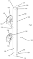
Figure 1 illustrates an assembly including an advertising board and apparatus according to certain embodiments of the present invention for mounting the advertising board to a window of a building; -
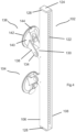
Figure 2 illustrates a front side of the apparatus in an open configuration; -
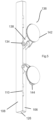
Figure 3 illustrates a rear side of the apparatus in the open configuration; -
Figure 4 illustrates the front side of the apparatus in a closed configuration; -
Figure 5 illustrates the rear side of the apparatus in the closed configuration; and -
Figure 6 illustrates an exploded view of the assembly ofFigure 1 . - As illustrated in
Figure 1 ,apparatus 100 according to certain embodiments of the present invention for mounting adisplay board 200, e.g. an advertising board, to a window of a building, includes aclamping portion 102 and amounting portion 104. Theclamping portion 102 is configured to receive and releasably hold an edge region of a substantially planar advertising board to allow the same to be supported with respect to a window on which themounting portion 104 is securely mounted. - As illustrated in
Figures 2 and3 , theclamping portion 102 comprises a fixedelongate base member 106 for receiving an edge region of an advertising board, and a moveableelongate clamp member 108 coupled to thebase member 106 by a plurality of spaced aparthinges 110 to allow theclamp member 108 to rotate with respect to thebase member 106 between open and closed positions.Figures 2 and3 illustrate theclamping portion 102 in an open state for receiving or removing an end region of an advertising board, andFigures 4 and5 illustrate theclamping portion 102 in a closed state for securely clamping the edge region of the advertising board therein. - The
base member 106 includes abase wall region 112 for supporting the edge region of the advertising board, and arear wall region 114 for limiting movement of the advertising board when the same is slidably inserted into and onto thebase member 106 from an open front region thereof. Therear wall region 114 acts as a stop to indicate to an installer that the edge region of the advertising board has been fully inserted into thebase member 106 and theclamp member 108 can then be closed onto the board to clamp the same between the clamp member and the base member. Thebase member 106 also includes opposed upper and lower wall regions 116,118 to limit vertical movement of the board when received in the base member and also to help guide the board into the base member when slidably inserted therein. - The
clamp member 108 includes aclamping wall region 120 to engage the edge region of the advertising board when in the closed position and clamp it against thebase member 106. Theclamping wall region 120 includes a plurality ofprojections 122 to grip the advertising board and prevent the same slipping when clamped. Aptly, theprojections 122 comprise at least one row of teeth and preferably, as illustrated, two or more rows of teeth to securely engage and clamp the advertising board. Thebase member 106 may also include corresponding teeth, such as one row of teeth that locates in between two rows of teeth inside theclamp member 108 when the same is in the closed position with respect to thebase member 106. Theprojections 122 may comprise intermittent and longitudinally spaced apart set of projections arranged in a single row or two or more parallel rows. Alternatively, theprojections 122 may comprise a pattern of domed protrusions for example. - The
clamp member 108 also includes opposed upper and lower wall regions or tabs 124,126 extending inwardly and substantially perpendicularly from the elongateclamping wall region 120 to respectively slide over the upper and lower wall regions 116,118 of thebase member 106 as theclamp member 108 is being closed. Each of the upper and lower wall regions or tabs 124,126 of theclamp member 108 includes an inwardly extending projection/rib 128 at its free end configured to snap over the respective edge of the base member and engage the outer surface of thebase wall region 112 of thebase member 106 when theclamp member 108 is in the closed position. This locking portion of the apparatus thereby releasably locks theclamp member 108 in the closed position with respect to thebase member 106 and prevents theclamping portion 102 unintentionally opening in use. The upper and lower wall regions or tabs 124,126 are substantially resilient to allow them to flex outwardly whilst theclamp member 108 is being closed and then snap back when the respective projection/rib 128 has cleared the respective wall region, whilst also allowing them to be manually urged upwardly and downwardly respectively to clear the projection/rib 128 from the edge of the base member and allow theclamp member 108 to be unlocked and opened with respect to thebase member 106. Other suitable locking arrangements may be used to ensure the clamp member does not unintentionally open in use, such as projections and recesses, clips, latches, or the like. A hasp and staple assembly or the like may be provided to allow a padlock or the like to lock theclamp member 108 in the closed position and prevent theclamping portion 102 being maliciously opened by an unauthorised person. Alternatively, for example to accommodate different thicknesses of advertising board, theclamp member 108 may not be rotatably coupled to thebase member 106 by hinges but may be separate from the base member when theclamping portion 102 is in an open state and slidably engage with thebase member 108 when in the closed state, e.g. the clamp member may be translated towards the base member, instead of being rotated with respect to the base member about a hinge axis, and clipped on to the base member via, for example, a similar snap-fit arrangement as described above. An additional wall region or tabs extending from theclamping wall region 120 may be required for engagement with thebase wall region 112 of thebase member 106 to constrain the clamp member with respect to the base member in the forward-aft direction when the clamping portion is in a closed state. Alternatively, separate clips may be used to securely couple the upper and lower end regions of the base member and clamp member together when in the closed position and clamping the edge region of the advertising board therebetween. - As illustrated, two longitudinally spaced apart pairs of lugs 130,132 extend rearwardly from the
rear wall region 114 of thebase member 106. Adjacent ones of each pair of lugs are laterally spaced apart and are substantially parallel with each other. The adjacent lugs of each pair include laterally aligned through holes for mounting a bolt orhinge pin 134 through each pair of lugs. Asuction cup assembly 136 is pivotally coupled to each one of the two pairs of lugs 130,132 by a respective one of the bolts or hingepins 134 extending through holes in the free end regions of a corresponding pair of spaced apartarms 138 extending from a substantially rigidconcave body 140 of each suction cup assembly. Eachsuction cup assembly 136 further includes a resilientlydeformable cup part 142 for engaging a substantially smooth and planar support surface, such as a window pane, and a lever-actuatedmechanism 144 for moving thecup part 142 with respect to the support surface to thereby create or release a vacuum inside the cup to mount or remove the apparatus on or from the support surface. Aptly, the coupling/s between eachsuction cup assembly 136 and thebase member 106 of the clampingportion 102 may include a resilient element, such as a spring, to allow the clampingportion 102 to resiliently move, particularly laterally, with respect to the mountingportion 104 to prevent the apparatus from being damaged by strong wind, for example, or if impacted by a passer-by or vehicle either maliciously or unintentionally. For example, a compression spring may be located at each end of each bolt or hinge pin and between the outer surface of the base member lugs 130,132 and the bolt head and nut or washer respectively to thereby allow the clamping portion 102 (and advertising board clamped therein) to move/rotate laterally with respect to the mountingportion 104 when a lateral load is applied to the board, and to spring back to a neutral position when no load is being applied to the board. - The lugs 130,132 are located to each side and proximal to a centre of the
elongate base member 106 and thearms 138 are angled away from the central location, i.e. upwardly and downwardly from each lug respectively, which allows the suction cups to be located on a relatively small support area providing more flexibility of use. Thearms 138 extend from a perimetric region of each respective suction cup and the lever-actuatedmechanism 144 is located substantially centrally to be easily accessible and more effective. - In use, the
suction cups 136 of theapparatus 100 are offered up to a window pane and mounted thereto by actuating the levers to create a vacuum within each cup and securely attach the apparatus to the window pane. Theclamp member 108 is moved to the open position with respect to thebase member 106 and the advertising board is slidably received into and onto the base member. Theclamp member 108 is then rotated towards the base member and in turn the closed position such that the edge region of the advertising board is clamped between the rows of teeth provided on the inner surfaces of the base member and clamp member. The teeth engage into the resilient material of the advertising board to securely grip the same and clamp it to the apparatus. The clamp member is locked in the closed position via the upper and lower tabs - An alternative embodiment of the present invention may include a differently conformed mounting portion for mounting the clamping portion to a different type of support surface other than a window pane. For example, the mounting portion may comprise one or more clamp assemblies coupled to the clamping portion by arms or stems or the like, wherein the or each clamp assembly comprises a bracket or clamp arrangement for mounting the apparatus to a lamppost, scaffolding pole, or the like. Further alternatively, the mounting portion may comprise magnets coupled to the lugs of the base member, and/or by arms or stems or the like, for mounting the apparatus on a metallic support surface, such as the corrugated wall panels of an industrial unit or the like. Further alternatively, the suction cup assemblies may be removable from the arms and the parallel arms may be connected together at their free ends by a bridging region including a hole therethrough. The holes may be used to screw the clamping portion of the apparatus to a conventional timber post or stake for example or a fence post or the like. Further alternatively, when the suction cup assemblies are used to mount the apparatus to a window pane, the apparatus may include one or more straps for trapping between the window and its frame to thereby tether the apparatus to the building and provide a secondary/additional form of security.
- Aptly, the
apparatus 100 is made of a metallic or plastics material, such as stainless steel, aluminium, acrylonitrile styrene butadiene (ABS) or the like and may be formed by injection moulding, additive manufacturing, or the like. Aptly, the apparatus is configured to hold a standard sign that may measure 400 x 600mm and have a thickness that may vary but is typically around 1 0mm, and which may be made as a sandwich board in plastics. - Certain embodiments of the present invention therefore provide apparatus for removably mounting an advertising board to a substantially smooth surface of a building, such as a window pane, without requiring tools, specialist skills, multiple people, or compromising the integrity of the building or surrounding land. The apparatus is reusable and eliminates the need for a conventional timber support structure or post which can be easily damaged by wind or maliciously and is typically only used once before being discarded so the apparatus according to certain embodiments of the present invention is also environmentally friendly.
Claims (15)
- Apparatus for mounting a display board to a support surface, comprising:a mounting portion for mounting the apparatus to the support surface;a clamping portion for clamping an edge region of the display board to the apparatus, wherein the clamping portion comprises a base member for receiving the edge region of the display board and a clamp member moveable between an open position and a closed position with respect to the base member; anda locking portion for releasably locking the clamp member in the closed position.
- The apparatus according to claim 1, wherein the clamp member is coupled to the base member by one or more hinges to be rotatable between the open and closed positions.
- The apparatus according to claim 1 or 2, wherein the base member comprises an elongate base wall region for supporting the edge region of the display board, and an elongate rear wall region extending along the base wall region for limiting longitudinal movement of the display board when inserted into the base member from an open front region thereof.
- The apparatus according to claim 3, wherein the base member comprises opposed upper and lower wall regions extending from the base wall region for limiting lateral movement of the display board when received in the base member.
- The apparatus according to claim 4, wherein the clamp member comprises an elongate clamping wall region and the locking portion comprises opposed upper and lower tabs extending inwardly and substantially perpendicularly from the clamping wall region to engage an outer surface of the base member and lock the clamp member in the closed position.
- The apparatus according to claim 5, wherein each tab is substantially resilient and comprises a projection at a free end region thereof for engaging a respective edge region of the base member when the clamp member is in the closed position.
- The apparatus according to claim 5 or 6, wherein the clamp member comprises a plurality of projections for engaging and gripping the display board when the clamp member is in the closed position.
- The apparatus according to claim 7, wherein the plurality of projections comprises two longitudinally oriented rows of spaced apart and parallel teeth disposed on an inner surface of the elongate clamping wall region of the clamp member.
- The apparatus according to claim 8, wherein the base member comprises at least one longitudinally oriented row of teeth disposed on an inner surface of the elongate base wall region locatable between the two rows of teeth of the clamp member when the same is in the closed position.
- The apparatus according to any preceding claim, wherein the mounting portion comprising a plurality of suction cup assemblies coupled to the base member of the clamping portion, and wherein optionally each suction cup assembly is pivotally coupled to the base member by a hinge pin or bolt.
- The apparatus according to claim 10, wherein each suction cup assembly comprises a plurality of spaced apart and parallel arms extending therefrom and pivotally coupled to a corresponding pair of lugs extending outwardly from the base member, and wherein optionally each arm extends from a perimetric region of the respective suction cup assembly and at an obtuse angle.
- The apparatus according to claim 11, wherein each arm extends towards a centre region of the base member.
- The apparatus according to any of claims 10 to 12, wherein each suction cup assembly comprises a substantially rigid concave body, a resiliently deformable cup part mounted therein, and a lever-actuated mechanism for moving the cup part with respect to the cup body and the support surface to thereby create or release a vacuum inside the cup part to mount or remove the apparatus on or from the support surface.
- The apparatus according to any preceding claim, wherein the mounting portion comprises at least one resilient element for resiliently reacting to a force applied laterally to the display board in use to thereby return the display board to a neutral position when no force is being applied laterally to the display board, and wherein optionally the at least one resilient element comprises at least one spring located between the mounting portion and the clamping portion.
- An assembly comprising apparatus according to any preceding claim and a display board.
Applications Claiming Priority (1)
| Application Number | Priority Date | Filing Date | Title |
|---|---|---|---|
| GBGB2319609.0A GB202319609D0 (en) | 2023-12-20 | 2023-12-20 | A display device for a planar advertising board |
Publications (1)
| Publication Number | Publication Date |
|---|---|
| EP4576050A1 true EP4576050A1 (en) | 2025-06-25 |
Family
ID=89662698
Family Applications (1)
| Application Number | Title | Priority Date | Filing Date |
|---|---|---|---|
| EP24221457.5A Pending EP4576050A1 (en) | 2023-12-20 | 2024-12-19 | Apparatus for mounting a display board |
Country Status (3)
| Country | Link |
|---|---|
| EP (1) | EP4576050A1 (en) |
| GB (2) | GB202319609D0 (en) |
| IE (1) | IE20240770A2 (en) |
Citations (6)
| Publication number | Priority date | Publication date | Assignee | Title |
|---|---|---|---|---|
| US5390889A (en) * | 1993-11-12 | 1995-02-21 | Hiscock; Anthony S. | Poster clamp |
| DE29611662U1 (en) * | 1996-03-11 | 1996-10-24 | Malessa, Martin, 51067 Köln | Modular advertising device with suction cups |
| US5664749A (en) * | 1995-10-05 | 1997-09-09 | Fasteners For Retail, Inc. | Adjustable sign holders |
| KR200474231Y1 (en) * | 2013-07-26 | 2014-09-05 | 강창기 | An absorbing device for fixing a banner |
| US9898940B2 (en) * | 2015-03-20 | 2018-02-20 | K-International, Inc. | Ladderless cleat and track banner hanger for vertical surface |
| US10334968B2 (en) * | 2016-09-07 | 2019-07-02 | T.M. Shea Products, Inc. | Bracket assemblies for signage systems and merchandising display systems |
Family Cites Families (5)
| Publication number | Priority date | Publication date | Assignee | Title |
|---|---|---|---|---|
| CA2035706C (en) * | 1991-02-05 | 1999-03-16 | Adrian W. Pynenburg | Snap closing panel holder |
| US7086346B1 (en) * | 2004-09-16 | 2006-08-08 | Van Horn Steven M | Apparatus as a flag or banner pole clip |
| US8196325B2 (en) * | 2007-04-30 | 2012-06-12 | Rose Displays, Ltd | Front loading frame display arrangement |
| CA2704324A1 (en) * | 2010-05-17 | 2011-11-17 | Roman Semeniuk | Hanger for sheet material |
| KR101993691B1 (en) * | 2018-07-16 | 2019-06-27 | 이장복 | Prevention of pollution function improved mold type signpost and coupler of signpost |
-
2023
- 2023-12-20 GB GBGB2319609.0A patent/GB202319609D0/en not_active Ceased
-
2024
- 2024-04-29 GB GB2405978.4A patent/GB2639678A/en active Pending
- 2024-12-19 EP EP24221457.5A patent/EP4576050A1/en active Pending
- 2024-12-19 IE IE20240770A patent/IE20240770A2/en unknown
Patent Citations (6)
| Publication number | Priority date | Publication date | Assignee | Title |
|---|---|---|---|---|
| US5390889A (en) * | 1993-11-12 | 1995-02-21 | Hiscock; Anthony S. | Poster clamp |
| US5664749A (en) * | 1995-10-05 | 1997-09-09 | Fasteners For Retail, Inc. | Adjustable sign holders |
| DE29611662U1 (en) * | 1996-03-11 | 1996-10-24 | Malessa, Martin, 51067 Köln | Modular advertising device with suction cups |
| KR200474231Y1 (en) * | 2013-07-26 | 2014-09-05 | 강창기 | An absorbing device for fixing a banner |
| US9898940B2 (en) * | 2015-03-20 | 2018-02-20 | K-International, Inc. | Ladderless cleat and track banner hanger for vertical surface |
| US10334968B2 (en) * | 2016-09-07 | 2019-07-02 | T.M. Shea Products, Inc. | Bracket assemblies for signage systems and merchandising display systems |
Also Published As
| Publication number | Publication date |
|---|---|
| GB2639678A (en) | 2025-10-01 |
| GB202405978D0 (en) | 2024-06-12 |
| IE20240770A2 (en) | 2025-09-10 |
| GB202319609D0 (en) | 2024-01-31 |
Similar Documents
| Publication | Publication Date | Title |
|---|---|---|
| US7559715B2 (en) | Hurricane panel fastening device | |
| US4547009A (en) | Strike plate and hinge for a high security door system | |
| AU2015101235B4 (en) | Handle | |
| US5623778A (en) | Weatherized posting board assembly | |
| US5364140A (en) | Door security device | |
| US20150191949A1 (en) | Door Barricade | |
| US11808068B2 (en) | Door locking device | |
| US5282539A (en) | Gun rack | |
| US4585259A (en) | Portable door locking device | |
| US5496081A (en) | Door security device | |
| US6560925B1 (en) | Door security device with glue on attachment | |
| US7415787B2 (en) | License plate frame | |
| US4903934A (en) | Picture frame fastening means | |
| US7178300B2 (en) | Latch-type tile mounting system | |
| US5360246A (en) | Latch plate for storage lockers | |
| JP2013529268A (en) | Door fixing bracket assembly | |
| GB2639678A (en) | Apparatus for mounting a display board | |
| US7232163B2 (en) | Sliding door lock | |
| US20090183658A1 (en) | Vault cover with vault door and spring-biased support arm | |
| CN211549195U (en) | Storage door lock | |
| AU2016203527B2 (en) | Door lock | |
| JP3427705B2 (en) | Distribution board inner lid mounting structure | |
| US6131968A (en) | Lock system for shed | |
| GB2099898A (en) | Door assembly | |
| US20240360699A1 (en) | Door lock device |
Legal Events
| Date | Code | Title | Description |
|---|---|---|---|
| PUAI | Public reference made under article 153(3) epc to a published international application that has entered the european phase |
Free format text: ORIGINAL CODE: 0009012 |
|
| STAA | Information on the status of an ep patent application or granted ep patent |
Free format text: STATUS: THE APPLICATION HAS BEEN PUBLISHED |
|
| AK | Designated contracting states |
Kind code of ref document: A1 Designated state(s): AL AT BE BG CH CY CZ DE DK EE ES FI FR GB GR HR HU IE IS IT LI LT LU LV MC ME MK MT NL NO PL PT RO RS SE SI SK SM TR |
|
| STAA | Information on the status of an ep patent application or granted ep patent |
Free format text: STATUS: THE APPLICATION IS DEEMED TO BE WITHDRAWN |