EP4575888A1 - Integrated circuit card able to boot in a user mode and in a maintenance mode - Google Patents
Integrated circuit card able to boot in a user mode and in a maintenance mode Download PDFInfo
- Publication number
- EP4575888A1 EP4575888A1 EP23307375.8A EP23307375A EP4575888A1 EP 4575888 A1 EP4575888 A1 EP 4575888A1 EP 23307375 A EP23307375 A EP 23307375A EP 4575888 A1 EP4575888 A1 EP 4575888A1
- Authority
- EP
- European Patent Office
- Prior art keywords
- integrated circuit
- reset
- circuit card
- maintenance
- user
- Prior art date
- Legal status (The legal status is an assumption and is not a legal conclusion. Google has not performed a legal analysis and makes no representation as to the accuracy of the status listed.)
- Pending
Links
Images


Classifications
-
- G—PHYSICS
- G06—COMPUTING OR CALCULATING; COUNTING
- G06K—GRAPHICAL DATA READING; PRESENTATION OF DATA; RECORD CARRIERS; HANDLING RECORD CARRIERS
- G06K19/00—Record carriers for use with machines and with at least a part designed to carry digital markings
- G06K19/06—Record carriers for use with machines and with at least a part designed to carry digital markings characterised by the kind of the digital marking, e.g. shape, nature, code
- G06K19/067—Record carriers with conductive marks, printed circuits or semiconductor circuit elements, e.g. credit or identity cards also with resonating or responding marks without active components
- G06K19/07—Record carriers with conductive marks, printed circuits or semiconductor circuit elements, e.g. credit or identity cards also with resonating or responding marks without active components with integrated circuit chips
-
- G—PHYSICS
- G06—COMPUTING OR CALCULATING; COUNTING
- G06K—GRAPHICAL DATA READING; PRESENTATION OF DATA; RECORD CARRIERS; HANDLING RECORD CARRIERS
- G06K7/00—Methods or arrangements for sensing record carriers, e.g. for reading patterns
- G06K7/0013—Methods or arrangements for sensing record carriers, e.g. for reading patterns by galvanic contacts, e.g. card connectors for ISO-7816 compliant smart cards or memory cards, e.g. SD card readers
Definitions
- the present disclosure relates to integrated circuit cards.
- Integrated circuit cards especially cards compliant with the ISO7816-3 standard, may be subject to various issues (tearing, security breaches, etc.).
- terms "ISO7816-3" or “ISO7816-3 standard” refers to the standard “ISO/IEC 7816-3 Novembre 2006”.
- an analysis may be performed in order to find out what happened in the faulty card.
- the memory of the card may be dumped.
- the predefined period goes from 400 clock cycles after the reset time to 40000 clock cycles after the reset time.
- the predefined word is coded on a single byte and/or has a hexadecimal value of A5.
- the set of maintenance commands include commands requesting a status of the integrated circuit card, wherein the status comprises at least one of the following data:
- Another object of the present disclosure is a reader comprising:
- the predefined period goes from 400 clock cycles after the reset time to 40000 clock cycles after the reset time.
- the predefined word is coded on a single byte and/or has a hexadecimal value of A5.
- a further object of the present disclosure is a method implemented by an integrated circuit card, the method comprising:
- a system comprises an integrated circuit card (ICC) 1 and a reader 2.
- ICC integrated circuit card
- the electrical interface 10 comprises electrical contacts, each of the electrical contacts being able to carry a digital signal.
- a digital signal can have two states: a low state and a high state. A transition from the low state to the high state is called a rising edge, whereas a transition from the high state to the low state is called a falling edge.
- the electrical contacts further comprise:
- the maintenance OS is different from the user OS.
- the maintenance OS comprises code instructions for processing a set of maintenance command more restricted than the set of user commands.
- the boot manager 16 may be the processor 14, a component of the processor 14, or a circuit distinct from the processor 14 as shown in figure1 .
- Boot manager may be also a specific module or function containing specific code instructions which when executed by the processor cause the management of the booting modes (make the integrated circuit to boot into maintenance mode or into user).
- the electrical contacts of the reader 2 are eight in number and meets all the requirements already described above in relation with the ICC 1.
- the user reset sequence implemented by the controller 22 of the reader 2 comprises the follows steps, while the electric interface 20 of the reader 2 is connected to the electrical interface 10 of the ICC 1.
- the controller 22 causes a power signal carried by the power contact VCC to have a rising edge at a time referred to as "powering time". As explained before, a rising edge is a signal transition from the low state to the high state.
- the controller 22 causes a clock signal carried by the clock contact CLK to have a rising edge at a time Ta, referred to as "clock starting time Ta" hereinafter. Ta is after the powering time.
- the controller 22 causes an input/output signal carried by the input/output contact I/O to have a rising edge at a time which is subsequent to the clock starting time Ta and delayed from Ta by a delay t a .
- the delay t a is lower or equal to 200/f, where f is a clock frequency used for communications between the reader 2 and the ICC 1.
- the delay t a has a duration lower or equal to 200 clock cycles and the input/output signal has to have a rising edge within 200 clock cycles (delay t a ) after the clock starting time Ta (at time Ta + t a ).
- the clock signal is provided by the reader 2 to the ICC 1 and consequently the clock cycle is controlled by the reader 2.
- the controller 22 causes a reset signal carried by the reset contact RST to have a rising edge at a time Tb, referred to as "reset time Tb" hereinafter.
- the reset time Tb is after the clock starting time Ta and delayed from Ta by a delay t b .
- the delay t b between Ta and Tb is at least 400 clock cycles ( t b is greater or equal to 400/f).
- the controller 22 causes the input/output signal to have a falling edge at a time subsequent to Tb, and delayed from Tb by a delay t c .
- the delay tc is included in a predefined range. Therefore, the time of the falling edge of the input/output signal is included in a predefined period after the reset time Tb, said predefined period having a duration equal to the duration of the predefined range.
- the predefined range is as follows: 400 / f ⁇ t c ⁇ 40000 / f
- the predefined period goes from 400 clock cycles after the reset time Tb to 40000 clock cycles after the reset time Tb.
- the controller 22 waits for an answer from the ICC 1 via the input/output contact.
- the answer from the ICC 1 via the input/output contact shall begin between 400 and 40000 clock cycles (delay t c ) after the reset time Tb (at time Tb + t c ).
- the controller 22 expects the answer to start within the predefined period mentioned above.
- the reader 2 expects ICC 1 to cause the input / output signal to have a falling edge.
- the entity e.g. ICC 1 that set the input / output signal to have a falling edge will be the entity that will be in transmission mode and will have the control to manage the input/output signal while the other entity (e.g. reader 2) will be in reception mode and will only have access read only on the input / output contact.
- This user reset sequence complies with the requirements of the ISO 7816 standard.
- the maintenance reset sequence implemented by the controller 22 of the reader 2 comprises the follows steps, while the electric contacts of the reader 2 are connected to the electrical contacts of the ICC 1.
- the controller 22 causes a power signal carried by the power contact VCC to have a rising edge at the powering time, like in the user reset sequence.
- the controller 22 causes a clock signed carried by the clock contact CLK to have a rising edge at the clock starting time Ta, like in the user reset sequence.
- the controller 22 causes an input/output signal carried by the input/output contact I/O to have a rising edge at a time which is subsequent to the clock enabling time Ta and delayed from Ta by a delay t a , like in the user reset sequence.
- the controller 22 causes a reset signal carried by the reset contact RST to have a rising edge at the reset time Tb, like in the user reset sequence.
- the controller 22 causes the input/output signal to have a falling edge at a time subsequent to Tb, and delayed from Tb by a delay t c .
- the delay tc is included in the predefined range already discussed above.
- the controller 22 Instead of waiting an answer from the ICC 1, the controller 22 causes a predefined word to be sent to the input/output contact within the predefined period after the reset time (Tb) already discussed above in relation with the user reset sequence.
- this predefined period goes from 400 clock cycles after the reset time Tb to 40000 clock cycles after the reset time Tb.
- generating the '5A' character requires 12 ETU (for Elementary Time Unit, which is the nominal bit duration) including: 1 ETU to encode 1 start bit (state L), 8 ETU is required to encode one character ('5A' character), 1 ETU for parity bit, and 2 ETU for the guard time (state H).
- one ETU is equal to 372 clock cycles.
- the duration to send the predefined word coded on a single byte is this example (e.g. character "5A") will be equal to 4464 clock cycles (12 ETU multiplied by 372 clock cycles).
- the predefined word starts to be sent by the reader 2 at the starting time of this predefined period, i.e. at 400 clock cycles after the reset time Tb.
- the predefined word is sent later than this starting time, as long as the transmission of the predefined word is over before or at the ending time of the predefined period (i.e. at 40000 clock cycles after the reset time Tb).
- the time to send the predefined word can be equal to 400 clock cycles ⁇ T, where T is in clock cycles unit.
- the maximum value of T is 35536 and its minimum value is -400.
- the predefined word shall be sent between 400 clock cycles and 35536 clock cycles after the reset time Tb.
- the time to send the predefined word is configurable, stored in the memory 12 of the reader 2 and may be configured during the personalization. The configuration of the time to send the predefined word is done by adjusting the value T which shall belong to the time interval of 400 clock cycles after the reset time Tb and 35536 clock cycles after the reset time Tb.
- a method performed by the ICC 1 comprises the steps below.
- the boot manager 16 detects a reset sequence implemented by the reader 2 while the reader 2 is connected to the ICC 1.
- Detecting the maintenance reset sequence comprises detecting that the reader 2 has controlled the state of the digital signals carried by the electric contacts of the reader 2 as explained above in relation with figure 4 . Moreover, detecting the maintenance reset sequence comprises detecting that the reader 2 has sent the predefined word within the predefined period. This implies that: i) the reader 2 must have sent a word within said predefined period and ii) said word must match in length and value with the predefined word.
- the boot manager 16 may read the predefined word using a retry mechanism.
- the retry mechanism consists in watching the input/output line if there is a start bit that indicates a character has arrived.
- the number of retries can be stored in the memory 12 of the ICC 1, and may be configured during personalization. A smaller number for retries will decrease the time overhead dedicated to the detection of the predefined word. However, abigger number of retry will increase time overhead but reduce the risk of a missed detection of the predefined word.
- the ICC 1 may send the first byte of ATR (for Answer To Reset) ISO7816-3, noted TS byte.
- the TS byte has a hexadecimal value of '3B' and indicates "state H encodes value 1 and moment 2 of character frame conveys the least significant bit (lsb first)" based on ISO7816-3 standard.
- the boot manager 16 may choose the TS byte to be sent before starting the user OS or the maintenance OS.
- the boot manager 16 causes the ICC 1 to boot in the user mode. This implies that the user OS is selectively started (step 104).
- the boot manager 16 may send to the reader 2 via the input/output contact data indicating that the ICC 1 has booted or is booting in the user mode. These data correspond to a user mode Answer To Reset (user mode ATR).
- the boot manager 16 causes the ICC 1 to boot in the maintenance mode. This implies that the maintenance OS is selectively started (step 105).
- the boot manager 16 may send to the reader 2 via the input/output contact data indicating that the ICC 1 has booted or is booting in the maintenance mode (107). These data correspond to a specific ATR that is different from the user mode ATR. It indicates to the reader 2 that the ICC 1 has booted or is booting in the maintenance mode.
- the boot manager may detect at step 100 that the reader 2 has implemented a sequence different from the user reset sequence and from the maintenance reset sequence. In this case, steps 104, 105 are not performed. In other words, the boot managers ensures that neither the user OS nor the maintenance OS is booted.
- the ICC 1 is response the set of maintenance commands only, the set of maintenance commands being more restricted than the set of user commands.
- the maintenance commands may include an authentication command.
- the ICC 1 checks whether the reader 2 has the right to interact with the ICC 1 in the maintenance mode. Such a process outputs an authentication result indicated whether the authentication processed has succeeded or failed.
- the ICC 1 may reset and/or switch into the user mode by starting the user OS.
- the maintenance OS waits for further maintenance commands.
- the maintenance commands may include status commands requesting various statuses of the ICC 1.
- the maintenance command may comprise four status commands requesting the following statuses, respectively.
- a first status is a tearing event status comprising data describing tearing events detected by the ICC 1.
- Said data may include multiple tearing events (write, transaction, unitary recovery, trans recovery) associated with memory 12 addresses and occurrences.
- a second status is a memory 12 leak event status comprising data describing memory 12 leaks in a memory 12 of the ICC 1.
- Said data may include a number of garbage collections performed, information on the deleted objects owner(s), on number of deleted objects for each owner.
- a third status is a security status comprising data describing security violations detected by the ICC 1.
- Said data may report a number of occurrences of the following events: a security reset due to a high supply (VCC) violation, a security reset due to a high frequency violation, a security reset due to a low frequency violation.
- Said data may also provide the address and the number of occurrences of a memory 12 violation on erasing or on programming.
- Said data may also provide a number of stack overflows that occurred in the ICC 1.
- a fourth status is a card endurance status comprising data describing a level of endurance of the memory 12 of the ICC 1. This data may report a number of consumed sectors.
- the set of maintenance commands may consist of the authentication command and of at least one of the status commands described above.
Landscapes
- Engineering & Computer Science (AREA)
- Physics & Mathematics (AREA)
- General Physics & Mathematics (AREA)
- Theoretical Computer Science (AREA)
- Artificial Intelligence (AREA)
- Computer Vision & Pattern Recognition (AREA)
- Computer Hardware Design (AREA)
- Microelectronics & Electronic Packaging (AREA)
- Storage Device Security (AREA)
Abstract
Description
- The present disclosure relates to integrated circuit cards.
- Integrated circuit cards, especially cards compliant with the ISO7816-3 standard, may be subject to various issues (tearing, security breaches, etc.). In the present disclosure, terms "ISO7816-3" or "ISO7816-3 standard" refers to the standard "ISO/IEC 7816-3 Novembre 2006".
- When an issue occurs in an integrated circuit card, an analysis may be performed in order to find out what happened in the faulty card. For that purpose, the memory of the card may be dumped.
- However, this procedure is long, and dumping the memory dump may not provide sufficient information to understand what happened in the fault card.
- A goal of the present disclosure is to allow easy diagnosis of an integrated circuit card.
- This goal is achieved by an integrated circuit card comprising:
- an electrical interface for communicating with a reader, wherein the electrical interface includes a reset contact and an input/output contact;
- a boot manager configured to:
- ∘ detect a reset sequence implemented by the reader while the reader is connected to electrical interface,
- ∘ whenever the detected reset sequence is a user reset sequence, cause the integrated circuit card to boot in a user mode wherein the integrated circuit card is responsive to a set of user commands;
- ∘ whenever the detected reset sequence is a maintenance reset sequence, cause the integrated circuit to boot in a maintenance mode wherein the integrated circuit card is responsive to a set of maintenance commands only, the set of maintenance commands being more restricted than the set of user commands;
- causing a reset signal carried by the reset contact to have a rising edge at a reset time,
- sending a predefined word to the integrated circuit card via the input/output contact within a predefined period after the reset time; and
- causing the reset signal to have a rising edge at the reset time,
- causing a signal carried by the input/output contact to have a falling edge at a subsequent time included in the predefined period after the reset time, and
- waiting for an answer from the integrated circuit card via the input/output contact after the subsequent time.
- The integrated circuit card may further comprise optional features which are detailed below, taken alone or combined whenever possible.
- Preferably, the predefined period goes from 400 clock cycles after the reset time to 40000 clock cycles after the reset time.
- Preferably, the predefined word is coded on a single byte and/or has a hexadecimal value of A5.
- Preferably:
- the electrical interface comprises a clock contact, and
- the user reset sequence comprises causing a clock signal carried by the clock contact to have a rising edge at a clock starting time before the reset time.
- Preferably, a delay from the clock starting time to the reset time is greater or equal to 400 clock cycles.
- Preferably, the user reset sequence comprises causing an input/output signal carried by the input/output electric contact to have a rising edge at a time between the clock starting time and the reset time.
- Preferably, a delay ta from the clock starting time to the time of the rising edge of the input/output signal is lower or equal to 200 clock cycles.
- Preferably:
- the electrical interface includes a power contact for supplying the integrated circuit card with power, and
- the user reset sequence comprises causing a power signal carried by the power contact to have a rising edge before the clock starting time.
- Preferably:
- the set of maintenance commands do not comprise any command modifying contents of the integrated circuit card, and
- the set of user commands comprises at least one commands modifying contents of the integrated circuit card.
- Preferably the set of maintenance commands include commands requesting a status of the integrated circuit card, wherein the status comprises at least one of the following data:
- data describing tearing events detected by the integrated circuit card,
-
data describing memory 12 leaks in amemory 12 of the integrated circuit card, - data describing security violations detected by the integrated circuit card, and
- data describing a level of endurance of a
memory 12 of the integrated circuit card. - Preferably:
- booting in the user mode comprises starting a user operating system comprising code instructions for processing the set of user commands,
- booting in the maintenance mode comprises starting a maintenance operating system comprising code instructions for processing the set of maintenance commands, wherein the maintenance operating system is different from the user operating system.
- Another object of the present disclosure is a reader comprising:
- an electrical interface for communicating with an integrated circuit card, wherein the electrical interface comprises a reset contact and an input/output contact;
- a controller configured to implement:
- ∘ a user reset sequence causing the integrated circuit card to boot in a user mode wherein the integrated circuit card is responsive to a set of user commands, and
- ∘ a maintenance reset sequence causing the integrated circuit card to boot in a maintenance mode wherein the integrated circuit card is responsive to a set of maintenance commands only, wherein the set of maintenance commands is more restricted than the set of user commands;
- causing a reset signal carried by the reset contact to have a rising edge at a reset time,
- sending a predefined word to the integrated circuit card via the input/output contact within a predefined period after the reset time; and
- causing the reset signal to have a rising edge at the reset time,
- causing a signal carried by the input/output contact to have a falling edge at a subsequent time included in the predefined period after the reset time, and
- waiting for an answer from the integrated circuit card via the input/output contact after the subsequent time.
- The reader may further comprise optional features which are detailed below, taken alone or combined whenever possible.
- Preferably, the predefined period goes from 400 clock cycles after the reset time to 40000 clock cycles after the reset time.
- Preferably, the predefined word is coded on a single byte and/or has a hexadecimal value of A5.
- A further object of the present disclosure is a method implemented by an integrated circuit card, the method comprising:
- detecting a reset sequence implemented by a reader while the reader is connected to the integrated circuit card,
- whenever the detected reset sequence is a user reset sequence, causing the integrated circuit card to boot in a user mode wherein the integrated circuit card is responsive to a set of user commands less restricted than a set of maintenance commands;
- whenever the detected reset sequence is a maintenance reset sequence, causing the integrated circuit card to boot in a maintenance mode wherein the integrated circuit card is responsive to the set of maintenance commands only, wherein the set of maintenance commands is more restricted than the set of user commands,
- causing a reset signal carried by the reset contact to have a rising edge at a reset time,
- sending a predefined word to the integrated circuit card via the input/output contact within a predefined period after the reset time; and
- causing the reset signal to have a rising edge at the reset time,
- causing a signal carried by the input/output contact to have a falling edge at a subsequent time included in the predefined period after the reset time, and
- waiting for an answer from the integrated circuit card via the input/output contact after the subsequent time.
- Further details, features and advantages are explained in more detail below with the aid of exemplary embodiments that are illustrated in the figures.
-
Figure 1 schematically depicts a system comprising an integrated circuit card and a reader according to an embodiment. -
Figure 2 depicts electrical contacts of an integrated circuit card compliant with the ISO7816-3 standard. -
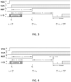
Figure 3 shows a user reset sequence for causing an integrated circuit card to boot in a normal mode. -
Figure 4 shows a user reset sequence for causing an integrated circuit card to boot in a maintenance mode. -
Figure 5 shows steps of a method implemented by a integrated circuit card according to an embodiment. - Referring to
figures 1 and 2 , a system comprises an integrated circuit card (ICC) 1 and areader 2. - The
ICC 1 comprises anelectrical interface 10 for communicating with thereader 2. - The
electrical interface 10 comprises electrical contacts, each of the electrical contacts being able to carry a digital signal. A digital signal can have two states: a low state and a high state. A transition from the low state to the high state is called a rising edge, whereas a transition from the high state to the low state is called a falling edge. - The
electrical interface 10 comprises: - a power contact for supplying the
ICC 1 with power, - a clock contact for carrying a clock signal,
- a reset contact,
- an input/output contact which providing a data communication channel between the
ICC 1 and thereader 2. Within the scope of this disclosure, the expression "I/O line" should be read as equivalent to words or notion linked to "input / output contact" or "data communication channel between ICC1 and thereader 2 provided by the input / output contact". - In the ISO7816-3 standard, the power contact is designated VCC or C1, the clock contact is designated CLK or C3, the reset contact is designated RST or C2, and the input/output contact is designated I/O or C7.
- The input/output contact I/O is bidirectional. Therefore, the
ICC 1 can receive data sent by thereader 2 via the input/output contact I/O and send data to thereader 2 via the input/output contact I/O. - When the
ICC 1 complies with the ISO7816-3 standard, the electrical contacts further comprise: - a ground contact, designated GND or C5, providing an electrical ground,
- a VPP or C6 contact, dedicated to program EEPROM of first generation ICCs. On new generation cards this contact may be no longer used.
- two RFU contacts C4, C8, reserved for further use.
- The
ICC 1 further comprises amemory 12. Thememory 12 stores two different computer programs: a user operating system (user OS) and a maintenance operating system (maintenance OS). - The
memory 12 may for instance be anEEPROM memory 12. - The user OS comprises code instructions for processing a set of user commands issued by the
reader 2 and transmitted to theICC 1 via the input/output contact I/O. When the user OS is running, theICC 1 is responsive to said user commands. At least one of the user commands may for instance request theICC 1 to participate to known cryptographic methods. Typically, some of the user commands may modify the contents of thememory 12. - The user OS comprises further code instructions for writing log data in the
memory 12. The log data provide information about events detected by theICC 1 and considered to be abnormal. - The log data may comprise:
- data describing tearing events detected by the
ICC 1, -
data describing memory 12 leaks in thememory 12 of theICC 1, - data describing security violations detected by the
ICC 1, and - data describing a level of endurance of the
memory 12. - The maintenance OS is different from the user OS. The maintenance OS comprises code instructions for processing a set of maintenance command more restricted than the set of user commands.
- The restricted character of the set of maintenance commands can be illustrated by the number of maintenance commands, which may be much lower than the number of user commands.
- Alternately of additionally, the restricted character of the set of maintenance commands can be illustrated by the nature of the maintenance commands. Advantageously, the set of maintenance commands do not comprise any command modifying the contents of the
memory 12. - The
ICC 1 further comprises aprocessor 14 for executing either the user OS or the maintenance OS. - The
ICC 1 further comprises aboot manager 16. A function played by a controller 22 (located in the reader 2) is to cause the integrated circuit to boot in a maintenance mode or in a user mode according to a method which will be described later. Booting in the maintenance mode comprises selectively starting the maintenance OS (the user OS is not started) whereas booting in the user mode comprises selectively starting the user OS (the maintenance OS is not started). - The
boot manager 16 may be theprocessor 14, a component of theprocessor 14, or a circuit distinct from theprocessor 14 as shown infigure1 . Boot manager may be also a specific module or function containing specific code instructions which when executed by the processor cause the management of the booting modes (make the integrated circuit to boot into maintenance mode or into user). - The
reader 2 comprises as well anelectrical interface 20 for communicating with theICC 1. - The
electrical interface 20 comprises electrical contacts. The electrical contacts are similar in number and in type to the electrical contacts of theICC 1. Each electrical contact of thereader 2 is adapted to be electrically connected to a corresponding electrical contact of theICC 1. - In particular, when the input/output contact I/O of the
reader 2 contacts the input/output contact I/O of theICC 1, both contacts form and allow the establishment of a communication channel between thereader 2 and theICC 1. - When the
reader 2 complies with the ISO7816-3 standard, the electrical contacts of thereader 2 are eight in number and meets all the requirements already described above in relation with theICC 1. - The
reader 2 may further comprise a slot for receiving at least in part theICC 1. When theICC 1 is received in the slot, the electrical contacts of theICC 1 are in contact with the electrical contacts of thereader 2. - The
reader 2 further comprises acontroller 22. A function played by thecontroller 22 is to implement a user reset sequence or a maintenance reset sequence for resetting theICC 1. Both sequences involve causing the electrical interface 20 (and therefore theelectrical interface 10 when theICC 1 is connected to the reader 2) to carry specific digital signals. - The maintenance reset sequence causes the
ICC 1 to boot the maintenance OS. As a result of this sequence, the ICC is set in a maintenance mode wherein theICC 1 is responsive to the set of maintenance commands only. - The user reset sequence causes the integrated circuit to boot the user OS. As a result of this sequence, the
ICC 1 is set in a user mode wherein theICC 1 is responsive to a set of user commands less restricted than the set of maintenance commands. In a user mode the set of user commands comprises at least one command one commands modifying contents of the integrated circuit card (1). - With reference to
figure 3 , the user reset sequence implemented by thecontroller 22 of thereader 2 comprises the follows steps, while theelectric interface 20 of thereader 2 is connected to theelectrical interface 10 of theICC 1. - At the beginning of the user reset sequence, all digital signals carried by all the electric contacts of the
reader 2 and of theICC 1 are at in the low state. - The
controller 22 causes a power signal carried by the power contact VCC to have a rising edge at a time referred to as "powering time". As explained before, a rising edge is a signal transition from the low state to the high state. - Then, the
controller 22 causes a clock signal carried by the clock contact CLK to have a rising edge at a time Ta, referred to as "clock starting time Ta" hereinafter. Ta is after the powering time. - Then, the
controller 22 causes an input/output signal carried by the input/output contact I/O to have a rising edge at a time which is subsequent to the clock starting time Ta and delayed from Ta by a delay ta . The delay ta is lower or equal to 200/f, where f is a clock frequency used for communications between thereader 2 and theICC 1. In other words, the delay ta has a duration lower or equal to 200 clock cycles and the input/output signal has to have a rising edge within 200 clock cycles (delay ta ) after the clock starting time Ta (at time Ta + ta ). The clock signal is provided by thereader 2 to theICC 1 and consequently the clock cycle is controlled by thereader 2. - Then, the
controller 22 causes a reset signal carried by the reset contact RST to have a rising edge at a time Tb, referred to as "reset time Tb" hereinafter. The reset time Tb is after the clock starting time Ta and delayed from Ta by a delay tb . The delay tb between Ta and Tb is at least 400 clock cycles (tb is greater or equal to 400/f). - Then, the
controller 22 causes the input/output signal to have a falling edge at a time subsequent to Tb, and delayed from Tb by a delay tc. The delay tc is included in a predefined range. Therefore, the time of the falling edge of the input/output signal is included in a predefined period after the reset time Tb, said predefined period having a duration equal to the duration of the predefined range. - When the
reader 2 complies with the ISO7816-3 standard, the predefined range is as follows:
- In that case, the predefined period goes from 400 clock cycles after the reset time Tb to 40000 clock cycles after the reset time Tb.
- From this point on, the
controller 22 waits for an answer from theICC 1 via the input/output contact. In other words, the answer from theICC 1 via the input/output contact shall begin between 400 and 40000 clock cycles (delay tc ) after the reset time Tb (at time Tb + tc). - The
controller 22 expects the answer to start within the predefined period mentioned above. In other words thereader 2 expectsICC 1 to cause the input / output signal to have a falling edge. Generally, the entity (e.g. ICC 1) that set the input / output signal to have a falling edge will be the entity that will be in transmission mode and will have the control to manage the input/output signal while the other entity (e.g. reader 2) will be in reception mode and will only have access read only on the input / output contact. - This user reset sequence complies with the requirements of the ISO 7816 standard.
- With reference to
figure 4 , the maintenance reset sequence implemented by thecontroller 22 of thereader 2 comprises the follows steps, while the electric contacts of thereader 2 are connected to the electrical contacts of theICC 1. - At the beginning of the maintenance reset sequence, all digital signals carried by all the electric contacts of the
reader 2 are at in the low state. - The
controller 22 causes a power signal carried by the power contact VCC to have a rising edge at the powering time, like in the user reset sequence. - Then, the
controller 22 causes a clock signed carried by the clock contact CLK to have a rising edge at the clock starting time Ta, like in the user reset sequence. - Then, the
controller 22 causes an input/output signal carried by the input/output contact I/O to have a rising edge at a time which is subsequent to the clock enabling time Ta and delayed from Ta by a delay ta , like in the user reset sequence. - Then, the
controller 22 causes a reset signal carried by the reset contact RST to have a rising edge at the reset time Tb, like in the user reset sequence. - Then, the
controller 22 causes the input/output signal to have a falling edge at a time subsequent to Tb, and delayed from Tb by a delay tc. The delay tc is included in the predefined range already discussed above. - Instead of waiting an answer from the
ICC 1, thecontroller 22 causes a predefined word to be sent to the input/output contact within the predefined period after the reset time (Tb) already discussed above in relation with the user reset sequence. - As a reminder, when the
reader 2 complies with the ISO7816-3 standard, this predefined period goes from 400 clock cycles after the reset time Tb to 40000 clock cycles after the reset time Tb. - The predefined word may be coded on a single byte. In that case, the predefined word is of the "char" type (character). A byte is the smallest piece of information which can be transferred from the
reader 2 to the integrated card, when said devices complies with the ISO7816-3 standard. - The predefined word may have a hexadecimal value of A5.
- For example, generating the '5A' character requires 12 ETU (for Elementary Time Unit, which is the nominal bit duration) including: 1 ETU to encode 1 start bit (state L), 8 ETU is required to encode one character ('5A' character), 1 ETU for parity bit, and 2 ETU for the guard time (state H). For example, one ETU is equal to 372 clock cycles. The duration to send the predefined word coded on a single byte is this example (e.g. character "5A") will be equal to 4464 clock cycles (12 ETU multiplied by 372 clock cycles).
- In an embodiment, the predefined word starts to be sent by the
reader 2 at the starting time of this predefined period, i.e. at 400 clock cycles after the reset time Tb. - In another embodiment, the predefined word is sent later than this starting time, as long as the transmission of the predefined word is over before or at the ending time of the predefined period (i.e. at 40000 clock cycles after the reset time Tb).
- When the predefined word is coded on a single byte, the time to send the predefined word can be equal to 400 clock cycles ± T, where T is in clock cycles unit. The maximum value of T is 35536 and its minimum value is -400. In other word the predefined word shall be sent between 400 clock cycles and 35536 clock cycles after the reset time Tb. The time to send the predefined word is configurable, stored in the
memory 12 of thereader 2 and may be configured during the personalization. The configuration of the time to send the predefined word is done by adjusting the value T which shall belong to the time interval of 400 clock cycles after the reset time Tb and 35536 clock cycles after the reset time Tb. - With reference to the
figure 5 a method performed by theICC 1 comprises the steps below. - In a
step 100, theboot manager 16 detects a reset sequence implemented by thereader 2 while thereader 2 is connected to theICC 1. - In practice, the reset sequence detected by the
boot manager 16 may be the user reset sequence described above, the maintenance reset sequence described above, or another sequence. - Detecting the user reset sequence comprises detecting that the
reader 2 has controlled the state of the digital signals carried by the electric contacts of thereader 2 as explained above in relation withfigure 3 . In particular, detecting the user reset sequence comprises detecting that thereader 2 has not sent the above discussed predefined word within the predefined period. - Detecting the maintenance reset sequence comprises detecting that the
reader 2 has controlled the state of the digital signals carried by the electric contacts of thereader 2 as explained above in relation withfigure 4 . Moreover, detecting the maintenance reset sequence comprises detecting that thereader 2 has sent the predefined word within the predefined period. This implies that: i) thereader 2 must have sent a word within said predefined period and ii) said word must match in length and value with the predefined word. - The
boot manager 16 may read the predefined word using a retry mechanism. In case of a mis-synchronization in thereader 2 or the card, there might be different timings between thereader 2 sending the predefined word and the card reading the input/output contact. The retry mechanism consists in watching the input/output line if there is a start bit that indicates a character has arrived. The number of retries can be stored in thememory 12 of theICC 1, and may be configured during personalization. A smaller number for retries will decrease the time overhead dedicated to the detection of the predefined word. However, abigger number of retry will increase time overhead but reduce the risk of a missed detection of the predefined word. - In a
step 102, theICC 1 may send the first byte of ATR (for Answer To Reset) ISO7816-3, noted TS byte. The TS byte has a hexadecimal value of '3B' and indicates "state H encodesvalue 1 andmoment 2 of character frame conveys the least significant bit (lsb first)" based on ISO7816-3 standard. Theboot manager 16 may choose the TS byte to be sent before starting the user OS or the maintenance OS. - If the reset sequence detected by the
boot manager 16 atstep 100 is the user reset sequence, theboot manager 16 causes theICC 1 to boot in the user mode. This implies that the user OS is selectively started (step 104). - In a
step 106, theboot manager 16 may send to thereader 2 via the input/output contact data indicating that theICC 1 has booted or is booting in the user mode. These data correspond to a user mode Answer To Reset (user mode ATR). - If the reset sequence detected by the
boot manager 16 atstep 100 is the maintenance reset sequence, theboot manager 16 causes theICC 1 to boot in the maintenance mode. This implies that the maintenance OS is selectively started (step 105). - Moreover, the
boot manager 16 may send to thereader 2 via the input/output contact data indicating that theICC 1 has booted or is booting in the maintenance mode (107). These data correspond to a specific ATR that is different from the user mode ATR. It indicates to thereader 2 that theICC 1 has booted or is booting in the maintenance mode. - The boot manager may detect at
step 100 that thereader 2 has implemented a sequence different from the user reset sequence and from the maintenance reset sequence. In this case, steps 104, 105 are not performed. In other words, the boot managers ensures that neither the user OS nor the maintenance OS is booted. - Once the
ICC 1 has booted in the maintenance mode, theICC 1 is response the set of maintenance commands only, the set of maintenance commands being more restricted than the set of user commands. - The maintenance commands may include an authentication command. When processing such an authentication command, the
ICC 1 checks whether thereader 2 has the right to interact with theICC 1 in the maintenance mode. Such a process outputs an authentication result indicated whether the authentication processed has succeeded or failed. - If the authentication result indicates that the authentication has failed, the
ICC 1 may reset and/or switch into the user mode by starting the user OS. - If the authentication result indicates that the authentication has succeeded, the maintenance OS waits for further maintenance commands.
- The maintenance commands may include status commands requesting various statuses of the
ICC 1. The maintenance command may comprise four status commands requesting the following statuses, respectively. - A first status is a tearing event status comprising data describing tearing events detected by the
ICC 1. Said data may include multiple tearing events (write, transaction, unitary recovery, trans recovery) associated withmemory 12 addresses and occurrences. - A second status is a
memory 12 leak event status comprisingdata describing memory 12 leaks in amemory 12 of theICC 1. Said data may include a number of garbage collections performed, information on the deleted objects owner(s), on number of deleted objects for each owner. - A third status is a security status comprising data describing security violations detected by the
ICC 1. Said data may report a number of occurrences of the following events: a security reset due to a high supply (VCC) violation, a security reset due to a high frequency violation, a security reset due to a low frequency violation. Said data may also provide the address and the number of occurrences of amemory 12 violation on erasing or on programming. Said data may also provide a number of stack overflows that occurred in theICC 1. - A fourth status is a card endurance status comprising data describing a level of endurance of the
memory 12 of theICC 1. This data may report a number of consumed sectors. - The set of maintenance commands may consist of the authentication command and of at least one of the status commands described above.
Claims (15)
- An integrated circuit card (1) comprising:• an electrical interface (10) for communicating with a reader (2), wherein the electrical interface includes a reset contact (RST) and an input/output contact (I/O);• a boot manager (16) configured to:wherein the maintenance reset sequence comprises:∘ detect a reset sequence implemented by the reader (2) while the reader (2) is connected to electrical interface (10),∘ whenever the detected reset sequence is a user reset sequence, cause the integrated circuit card (1) to boot in a user mode wherein the integrated circuit card (1) is responsive to a set of user commands;∘ whenever the detected reset sequence is a maintenance reset sequence, cause the integrated circuit to boot in a maintenance mode wherein the integrated circuit card (1) is responsive to a set of maintenance commands only, the set of maintenance commands being more restricted than the set of user commands;• causing a reset signal carried by the reset contact to have a rising edge at a reset time (Tb),• sending a predefined word to the integrated circuit card (1) via the input/output contact within a predefined period after the reset time (Tb); andwherein the user reset sequence does not comprise sending the predefined word, and comprises:• causing the reset signal to have a rising edge at the reset time (Tb),• causing a signal carried by the input/output contact to have a falling edge at a subsequent time included in the predefined period after the reset time (Tb), and• waiting for an answer from the integrated circuit card (1) via the input/output contact after the subsequent time.
- The integrated circuit card (1) of claim 1, wherein the predefined period goes from 400 clock cycles after the reset time (Tb) to 40000 clock cycles after the reset time (Tb).
- The integrated circuit card (1) of any one of claims 1 and 2, wherein the predefined word is coded on a single byte and/or has a hexadecimal value of A5.
- The integrated circuit card (1) of any one of claims 1 to 3, wherein:• the electrical interface (10) comprises a clock contact (CLK), and• the user reset sequence comprises causing a clock signal carried by the clock contact (CLK) to have a rising edge at a clock starting time (Ta) before the reset time (Tb).
- The integrated circuit card (1) of claim 4, wherein a delay (tb ) from the clock starting time (Ta) to the reset time (Tb) is greater or equal to 400 clock cycles.
- The integrated circuit card (1) of any one of claims 4 to 5, wherein the user reset sequence comprises causing an input/output signal carried by the input/output electric contact to have a rising edge at a time between the clock starting time (Ta) and the reset time (Tb).
- The integrated circuit card (1) of claim 6, wherein a delay (ta ) from the clock starting time (Ta) to the time of the rising edge of the input/output signal is lower or equal to 200 clock cycles.
- The integrated circuit card (1) of any one of claims 4 to 7, wherein:• the electrical interface (10) includes a power contact (VCC) for supplying the integrated circuit card (1) with power, and• the user reset sequence comprises causing a power signal carried by the power contact to have a rising edge before the clock starting time.
- The integrated circuit card (1) of any one of claim 1 to 8, wherein:• the set of maintenance commands do not comprise any command modifying contents of the integrated circuit card (1), and• the set of user commands comprises at least one commands modifying contents of the integrated circuit card (1).
- The integrated circuit card (1) of any one of claims 1 to 9, wherein the set of maintenance commands include commands requesting a status of the integrated circuit card (1), wherein the status comprises at least one of the following data:• data describing tearing events detected by the integrated circuit card (1),• data describing memory 12 leaks in a memory 12 of the integrated circuit card (1),• data describing security violations detected by the integrated circuit card (1), and• data describing a level of endurance of a memory 12 of the integrated circuit card (1).
- The integrated circuit card (1) of any one of claims 1 to 10, wherein:• booting in the user mode comprises starting a user operating system comprising code instructions for processing the set of user commands,• booting in the maintenance mode comprises starting a maintenance operating system comprising code instructions for processing the set of maintenance commands, wherein the maintenance operating system is different from the user operating system.
- A reader (2) comprising:• an electrical interface (20) for communicating with an integrated circuit card (1), wherein the electrical interface (20) comprises a reset contact (RST) and an input/output contact (I/O);• a controller (22) configured to implement:wherein the maintenance reset sequence comprises:∘ a user reset sequence causing the integrated circuit card (1) to boot in a user mode wherein the integrated circuit card (1) is responsive to a set of user commands, and∘ a maintenance reset sequence causing the integrated circuit card (1) to boot in a maintenance mode wherein the integrated circuit card (1) is responsive to a set of maintenance commands only, wherein the set of maintenance commands is more restricted than the set of user commands;• causing a reset signal carried by the reset contact to have a rising edge at a reset time (Tb),• sending a predefined word to the integrated circuit card (1) via the input/output contact within a predefined period after the reset time (Tb); andwherein the user reset sequence does not comprise sending the predefined word, and comprises:• causing the reset signal to have a rising edge at the reset time (Tb),• causing a signal carried by the input/output contact to have a falling edge at a subsequent time included in the predefined period after the reset time (Tb), and• waiting for an answer from the integrated circuit card (1) via the input/output contact after the subsequent time.
- The reader (2) of claim 12, wherein the predefined period goes from 400 clock cycles after the reset time to 40000 clock cycles after the reset time.
- The reader (2) of any one of claims 12 to 13, wherein the predefined word is coded on a single byte and/or has a hexadecimal value of A5.
- A method implemented by an integrated circuit card (1), the method comprising:• detecting (100) a reset sequence implemented by a reader (2) while the reader (2) is connected to the integrated circuit card (1),• whenever the detected reset sequence is a user reset sequence, causing the integrated circuit card (1) to boot (104) in a user mode wherein the integrated circuit card (1) is responsive to a set of user commands less restricted than a set of maintenance commands;• whenever the detected reset sequence is a maintenance reset sequence, causing the integrated circuit card (1) to boot (105) in a maintenance mode wherein the integrated circuit card (1) is responsive to the set of maintenance commands only, wherein the set of maintenance commands is more restricted than the set of user commands,wherein the maintenance reset sequence comprises:• causing a reset signal carried by the reset contact to have a rising edge at a reset time (Tb),• sending a predefined word to the integrated circuit card (1) via the input/output contact within a predefined period after the reset time (Tb); andwherein the user reset sequence does not comprise sending the predefined word, and comprises:• causing the reset signal to have a rising edge at the reset time (Tb),• causing a signal carried by the input/output contact to have a falling edge at a subsequent time included in the predefined period after the reset time (Tb), and• waiting for an answer from the integrated circuit card (1) via the input/output contact after the subsequent time.
Priority Applications (1)
| Application Number | Priority Date | Filing Date | Title |
|---|---|---|---|
| EP23307375.8A EP4575888A1 (en) | 2023-12-22 | 2023-12-22 | Integrated circuit card able to boot in a user mode and in a maintenance mode |
Applications Claiming Priority (1)
| Application Number | Priority Date | Filing Date | Title |
|---|---|---|---|
| EP23307375.8A EP4575888A1 (en) | 2023-12-22 | 2023-12-22 | Integrated circuit card able to boot in a user mode and in a maintenance mode |
Publications (1)
| Publication Number | Publication Date |
|---|---|
| EP4575888A1 true EP4575888A1 (en) | 2025-06-25 |
Family
ID=90362083
Family Applications (1)
| Application Number | Title | Priority Date | Filing Date |
|---|---|---|---|
| EP23307375.8A Pending EP4575888A1 (en) | 2023-12-22 | 2023-12-22 | Integrated circuit card able to boot in a user mode and in a maintenance mode |
Country Status (1)
| Country | Link |
|---|---|
| EP (1) | EP4575888A1 (en) |
Citations (1)
| Publication number | Priority date | Publication date | Assignee | Title |
|---|---|---|---|---|
| US20070095924A1 (en) * | 2003-12-17 | 2007-05-03 | Laurent Degauque | Fully simultaneous information on variation in status for an object with a dual interface |
-
2023
- 2023-12-22 EP EP23307375.8A patent/EP4575888A1/en active Pending
Patent Citations (1)
| Publication number | Priority date | Publication date | Assignee | Title |
|---|---|---|---|---|
| US20070095924A1 (en) * | 2003-12-17 | 2007-05-03 | Laurent Degauque | Fully simultaneous information on variation in status for an object with a dual interface |
Non-Patent Citations (1)
| Title |
|---|
| EMVCO: "Book 1 - Application Independent ICC to Terminal Interface Requirements", vol. 4,3 ; Contact, 30 November 2011 (2011-11-30), pages 1 - 189, XP061034461, Retrieved from the Internet <URL:https://www.emvco.com/wp-content/uploads/documents/EMV_v4.3_Book_1_ICC_to_Terminal_Interface_2012060705394541.pdf> [retrieved on 20200106] * |
Similar Documents
| Publication | Publication Date | Title |
|---|---|---|
| EP0800682B1 (en) | Chip card reader | |
| US20150012672A1 (en) | Ic card and ic card system having suspend/resume functions | |
| US10496912B2 (en) | Electronic unit with a secure element and method carried out in such an electronic unit facilitating communication with the secure element | |
| IL98077A (en) | Method and coupler for interfacing a portable data carrier with a host processor | |
| EP1615164B1 (en) | IC card with self-diagnostic function | |
| CN113361293A (en) | Card swiping method, card controller, electronic device and storage medium | |
| US6814295B2 (en) | Frequency sensor for each interface of a data carrier | |
| US9495315B2 (en) | Information processing device and data communication method | |
| US7014121B2 (en) | Method of self-detecting and dynamically displaying detected results for a card reader used to read flash memory cards | |
| EP0855672B1 (en) | Ic card reader/writer and its control method | |
| CN102722430A (en) | Method and device for detecting hot plug of secure digital card | |
| EP3365833B1 (en) | A method performed by an electronic device capable of communicating with a reader with improved self-testing | |
| EP2500845A2 (en) | Portable electronic apparatus | |
| KR20080018868A (en) | How to switch between memory card and memory card control | |
| US6760858B1 (en) | Method enabling an exchange of data between a smart card and an apparatus | |
| US20080093452A1 (en) | Method For Communicating By A Detector Of The Presence Of Chip Cards In A Reader Chip Cards And A Reading Device Communicating By The Presence Detector | |
| JP2004185419A (en) | Portable electronic medium, system for issuing portable electronic medium, processing method, and issuing method | |
| US11386192B2 (en) | Authentication token and method of operating the same | |
| JP2005025509A (en) | IC card system | |
| KR20030002149A (en) | Combi card | |
| JPH0289274A (en) | Memory card | |
| CN119988288A (en) | Driving method of SAM card device, SAM card device and storage medium | |
| JPH11282992A (en) | IC card | |
| JP2005122579A (en) | IC card and IC card software program compatible with multiple communication protocols | |
| JPH10307894A (en) | Method for discriminating ic card |
Legal Events
| Date | Code | Title | Description |
|---|---|---|---|
| PUAI | Public reference made under article 153(3) epc to a published international application that has entered the european phase |
Free format text: ORIGINAL CODE: 0009012 |
|
| STAA | Information on the status of an ep patent application or granted ep patent |
Free format text: STATUS: THE APPLICATION HAS BEEN PUBLISHED |
|
| AK | Designated contracting states |
Kind code of ref document: A1 Designated state(s): AL AT BE BG CH CY CZ DE DK EE ES FI FR GB GR HR HU IE IS IT LI LT LU LV MC ME MK MT NL NO PL PT RO RS SE SI SK SM TR |
|
| STAA | Information on the status of an ep patent application or granted ep patent |
Free format text: STATUS: REQUEST FOR EXAMINATION WAS MADE |
|
| STAA | Information on the status of an ep patent application or granted ep patent |
Free format text: STATUS: EXAMINATION IS IN PROGRESS |
|
| 17P | Request for examination filed |
Effective date: 20251006 |
|
| 17Q | First examination report despatched |
Effective date: 20251110 |
|
| P01 | Opt-out of the competence of the unified patent court (upc) registered |
Free format text: CASE NUMBER: UPC_APP_0005841_4575888/2026 Effective date: 20260217 |