EP4575731A1 - Active capacitive pen with magnetic rail cap - Google Patents
Active capacitive pen with magnetic rail cap Download PDFInfo
- Publication number
- EP4575731A1 EP4575731A1 EP24151264.9A EP24151264A EP4575731A1 EP 4575731 A1 EP4575731 A1 EP 4575731A1 EP 24151264 A EP24151264 A EP 24151264A EP 4575731 A1 EP4575731 A1 EP 4575731A1
- Authority
- EP
- European Patent Office
- Prior art keywords
- cartridge
- main bracket
- magnet
- circuit board
- bracket
- Prior art date
- Legal status (The legal status is an assumption and is not a legal conclusion. Google has not performed a legal analysis and makes no representation as to the accuracy of the status listed.)
- Pending
Links
Images


Classifications
-
- G—PHYSICS
- G06—COMPUTING OR CALCULATING; COUNTING
- G06F—ELECTRIC DIGITAL DATA PROCESSING
- G06F3/00—Input arrangements for transferring data to be processed into a form capable of being handled by the computer; Output arrangements for transferring data from processing unit to output unit, e.g. interface arrangements
- G06F3/01—Input arrangements or combined input and output arrangements for interaction between user and computer
- G06F3/03—Arrangements for converting the position or the displacement of a member into a coded form
- G06F3/033—Pointing devices displaced or positioned by the user, e.g. mice, trackballs, pens or joysticks; Accessories therefor
- G06F3/0354—Pointing devices displaced or positioned by the user, e.g. mice, trackballs, pens or joysticks; Accessories therefor with detection of two-dimensional [2D] relative movements between the device, or an operating part thereof, and a plane or surface, e.g. 2D mice, trackballs, pens or pucks
- G06F3/03545—Pens or stylus
-
- B—PERFORMING OPERATIONS; TRANSPORTING
- B43—WRITING OR DRAWING IMPLEMENTS; BUREAU ACCESSORIES
- B43K—IMPLEMENTS FOR WRITING OR DRAWING
- B43K23/00—Holders or connectors for writing implements; Means for protecting the writing-points
- B43K23/08—Protecting means, e.g. caps
-
- G—PHYSICS
- G06—COMPUTING OR CALCULATING; COUNTING
- G06F—ELECTRIC DIGITAL DATA PROCESSING
- G06F3/00—Input arrangements for transferring data to be processed into a form capable of being handled by the computer; Output arrangements for transferring data from processing unit to output unit, e.g. interface arrangements
- G06F3/01—Input arrangements or combined input and output arrangements for interaction between user and computer
- G06F3/03—Arrangements for converting the position or the displacement of a member into a coded form
- G06F3/033—Pointing devices displaced or positioned by the user, e.g. mice, trackballs, pens or joysticks; Accessories therefor
- G06F3/039—Accessories therefor, e.g. mouse pads
-
- G—PHYSICS
- G06—COMPUTING OR CALCULATING; COUNTING
- G06F—ELECTRIC DIGITAL DATA PROCESSING
- G06F3/00—Input arrangements for transferring data to be processed into a form capable of being handled by the computer; Output arrangements for transferring data from processing unit to output unit, e.g. interface arrangements
- G06F3/01—Input arrangements or combined input and output arrangements for interaction between user and computer
- G06F3/03—Arrangements for converting the position or the displacement of a member into a coded form
- G06F3/041—Digitisers, e.g. for touch screens or touch pads, characterised by the transducing means
- G06F3/044—Digitisers, e.g. for touch screens or touch pads, characterised by the transducing means by capacitive means
-
- H—ELECTRICITY
- H01—ELECTRIC ELEMENTS
- H01M—PROCESSES OR MEANS, e.g. BATTERIES, FOR THE DIRECT CONVERSION OF CHEMICAL ENERGY INTO ELECTRICAL ENERGY
- H01M50/00—Constructional details or processes of manufacture of the non-active parts of electrochemical cells other than fuel cells, e.g. hybrid cells
- H01M50/20—Mountings; Secondary casings or frames; Racks, modules or packs; Suspension devices; Shock absorbers; Transport or carrying devices; Holders
- H01M50/247—Mountings; Secondary casings or frames; Racks, modules or packs; Suspension devices; Shock absorbers; Transport or carrying devices; Holders specially adapted for portable devices, e.g. mobile phones, computers, hand tools or pacemakers
Definitions
- This invention involves the technical field of capacitive pen, and it concretely involves the improvement to a kind of active capacitive pen.
- Capacitive pen is a kind of pen that is made of conductive material, it has the characteristics of conduction and is used for touching to control capacitive screen, so as to finish operation of human-computer dialogue, and capacitive pen is a kind of auxiliary device for finishing human-computer dialogue through simulating human body by conductive material.
- capacitive pen does not simply substitute the operating function of finger, and more and more specialized personnels try to work on mobile equipment by active capacitive pen.
- this invention provides a kind of active capacitive pen with magnetic rail cap, which can cover the charging port while effectively taking into consideration its appearance, magnetic slide rail is adopted to greatly improve the operating feel, and it further solves the problem of not so good-looking exposed charging port, it is inappropriate to simply cover it, separated cap could be easily lost, and the experience of pulling feel is poor.
- a kind of active capacitive pen with magnetic rail cap it includes penholder, there is pen tip at the end of the said penholder, there is charging seat at the other end of the penholder that is far from the pen tip, there are main bracket and auxiliary bracket in the said penholder, a circuit board is fixed at the middle segment of the main bracket to match with the auxiliary bracket, one end of the circuit board is linked with the charging seat, the other end of the circuit board is linked with battery trough, which is mounted on the main bracket, there is induction coil on the said circuit board that is close to the main bracket, there is magnet trough at that position that is close to the induction coil, magnet set is installed in the magnet trough, there is touch induction needle on the circuit board, there is induction part at the position that corresponds to the said touch induction needle, and there is shielding layer outside the said
- the said cartridge assembly includes cartridge, upper cover of cartridge, lower cover of cartridge and cartridge FPC board.
- the said lower cover of cartridge is set at the front end of main bracket, the upper cover of cartridge and lower cover of cartridge are linked by matching to fix the cartridge, the line pins on the said cartridge FPC board are all electrically connected with the ground wire, first level signal line and second level signal line, and the exterior of the said upper cover of cartridge and lower cover of cartridge is fixed with the shielding tube through thread.
- charging seat, guide rail part and protecting crust at the tail of the said main bracket
- the said charging seat is interspersed to be fixed into the installation trough of the main bracket
- tailstock FPC board at the said charging seat
- the said tailstock FPC board is electrically connected with the circuit board through pin
- the said protecting crust covers onto the terminal exterior of the main bracket
- the said protecting crust is fixed to the main bracket through screw
- two guide rails for the said guide rail part they penetrates through the hole corresponding to one end of the protecting crust respectively, and they are hooked with the inner step of the protecting crust through the barb at the end of the guide rail part.
- the said magnet set includes magnet a and magnet b, the said magnet a is set into the end groove of the main bracket, the two said magnets b are respectively set into the root of the guide rail part, and they are located in the same horizontal plane as magnet a but their magnetism repels each other.
- this invention provides a kind of active capacitive pen with magnetic rail cap, and it has the following advantageous effect:
- There are charging seat, guide rail part and protecting crust at the tail of the main bracket the said charging seat is interspersed to be fixed into the installation trough of the main bracket, there is tailstock FPC board at the charging seat, the tailstock FPC board is electrically connected with the circuit board through pin, the said protecting crust covers onto the terminal exterior of the main bracket, the protecting crust is fixed to the main bracket through screw, there are two guide rails for the guide rail part, they penetrate through the hole corresponding to one end of the protecting crust respectively, and they are hooked with the inner step of the protecting crust through the barb at the end of the guide rail part, so as to realize covering the charging port while effectively taking into consideration its appearance, magnetic slide rail is adopted, so that it has the advantage of greatly improving the operating feel, and it further solves the problems of exposed charging port being not good-looking, simply covering being inappropriate, separated cap being prone to loss and experience of pulling feel being poor.
- this invention provides patent drawings, which are a part of the contents disclosed in this invention, they are mainly used for illustrating the example, and they can match with relevant description in the specification to explain the operation principle of example, by referencing those contents through matching, ordinary technical personnel of this domain should be capable of understanding other possible modes of carrying out and the advantages of this invention, the assemblies in drawings are not drawn in proportion, and similar assembly symbols are usually used for showing similar assemblies.
- a kind of active capacitive pen with magnetic rail cap is provided.
- this invention is further illustrated, as shown in Fig. 1-4 , according to a kind of active capacitive pen with magnetic rail cap in the example of this invention, it includes penholder 1, the material of penholder 1 is plastic or other nonmetallic or non-conductive material, there is pen tip 2 at end of the said penholder 1, there is charging seat 3 at the other end of the penholder 1 that is far from the pen tip 2, there are main bracket 4 and auxiliary bracket 5 in the penholder 1, a circuit board 6 is fixed at the middle segment of the main bracket 4 to match with the auxiliary bracket 5, one end of the circuit board 6 is linked with the charging seat 3, the other end of the circuit board 6 is linked with battery trough 10, which is mounted on the main bracket 4, there is induction coil 7 on the circuit board 6 that is close to the main bracket 4, there is magnet trough at that position that is close to the induction coil 7, magnet set 12 is installed in the magnet trough, there is touch induction needle 61 on the circuit board 6, there is induction part
- cartridge assembly 9 in the said pen tip 2
- the said cartridge assembly 9 includes cartridge 91, upper cover of cartridge 92, lower cover of cartridge 93 and cartridge FPC board 94
- the said lower cover of cartridge 93 is set at the front end of the main bracket 4
- the upper cover of cartridge 92 and lower cover of cartridge 93 are linked by matching to fix the cartridge 91
- the line pins on the said cartridge FPC board 94 are all electrically connected with the ground wire, first level signal line and second level signal line.
- Such an active capacitive pen is charged by magnetic wireless charging, the technical requirements for charging by adsorption on IPAD is simplified, its factory cost is greatly lowered, and more options are offered to users, and there is shielding tube 95 fixed to the upper cover of cartridge 92 and lower cover of cartridge 93 through thread.
- charging seat 41, guide rail part 42 and protecting crust 45 at the tail of the said main bracket 4 there are charging seat 41, guide rail part 42 and protecting crust 45 at the tail of the said main bracket 4, the said charging seat 41 is interspersed to be fixed into the installation trough of the main bracket 4, there is tailstock FPC board 411 at the said charging seat 41, the said tailstock FPC board 411 is electrically connected with the circuit board 6 through pin, the said protecting crust 45 covers onto the terminal exterior of the main bracket 4, the said protecting crust 45 is fixed to the main bracket 4 through screw, there are two guide rails for the said guide rail part 42, they penetrate through the hole corresponding to one end of the protecting crust 45 respectively, and they are hooked with the inner step of the protecting crust 45 through the barb at the end of the guide rail part 42.
- the said magnet set 12 includes magnet a121 and magnet b122, the said magnet a121 is set into the end groove of the main bracket 4, the two said magnets b 122 are respectively set into the root of the guide rail part42, and they are located in the same horizontal plane as magnet a121 but their magnetism repels each other.
- the magnet set that is set facilitates the capacitive pen to be adsorbed onto different equipment.
- the charging seat 41 is interspersed to be fixed into the installation trough of the main bracket 4, there is tailstock FPC board 411 at the charging seat 41, the said tailstock FPC board 411 is electrically connected with the circuit board 6 through pin, the said protecting crust 45 covers onto the terminal exterior of the main bracket 4, the protecting crust 45 is fixed to the main bracket 4 through screw, there are two guide rails for the said guide rail part 42, they penetrate through the hole corresponding to one end of the protecting crust 45 respectively, and they are hooked with the inner step of the protecting crust 45 through the barb at the end of the guide rail part 42.
- terminologies in this invention including “installation”, “setting”, “connection”, “fixing” and “rotary splicing” should be broadly understood, for example, it can be either permanent connection or detachable connection or being an integral whole; it can be either mechanical connection or electrical connection; it can be either direct connection or indirect connection through intermediate medium, it can be either the connection inside two elements or mutual interactive relationship between two elements, and except separately and explicitly restricted, for ordinary technical personnel in this domain, concrete meaning of the above terminologies in this invention can be understood according to concrete circumstances.
Landscapes
- Engineering & Computer Science (AREA)
- General Engineering & Computer Science (AREA)
- Theoretical Computer Science (AREA)
- General Physics & Mathematics (AREA)
- Physics & Mathematics (AREA)
- Human Computer Interaction (AREA)
- Computer Hardware Design (AREA)
- General Chemical & Material Sciences (AREA)
- Electrochemistry (AREA)
- Chemical Kinetics & Catalysis (AREA)
- Chemical & Material Sciences (AREA)
- Life Sciences & Earth Sciences (AREA)
- Biophysics (AREA)
- Charge And Discharge Circuits For Batteries Or The Like (AREA)
- Mechanical Pencils And Projecting And Retracting Systems Therefor, And Multi-System Writing Instruments (AREA)
Abstract
An active capacitive pen with magnetic rail cap includes a penholder, with a pen tip at one end and a seat at the other end away from the pen tip. The penholder houses multiple brackets and auxiliary brackets. A circuit board is securely positioned in the middle segment of the bracket to align with the auxiliary bracket. One end of the circuit board connects to the charging seat, and the other end connects to the battery trough, which is affixed to the primary bracket. An induction coil is situated on the circuit board, adjacent to the main bracket, with a magnet trough in close proximity. The magnet trough accommodates a magnet set. A touch induction needle is positioned on the circuit board, and an induction part corresponds to the touch induction needle's location. A shielding layer surrounds both the main bracket and auxiliary bracket.
Description
- This invention involves the technical field of capacitive pen, and it concretely involves the improvement to a kind of active capacitive pen.
- Capacitive pen is a kind of pen that is made of conductive material, it has the characteristics of conduction and is used for touching to control capacitive screen, so as to finish operation of human-computer dialogue, and capacitive pen is a kind of auxiliary device for finishing human-computer dialogue through simulating human body by conductive material. With the development of APP, the current capacitive pen does not simply substitute the operating function of finger, and more and more specialized personnels try to work on mobile equipment by active capacitive pen.
- Users become more and more familiar with active capacitive pen, and their requirements to appearance of pen get higher and higher, some people consider that exposed charging port is not so good-looking, it is inappropriate to simply cover it, separated cap could be easily lost, and the experience of pulling feel is poor.
- In order to meet the requirements of clients for solving the above problems, a kind of active capacitive pen with magnetic rail cap is introduced.
- Aimed at the shortcoming of existing technique, this invention provides a kind of active capacitive pen with magnetic rail cap, which can cover the charging port while effectively taking into consideration its appearance, magnetic slide rail is adopted to greatly improve the operating feel, and it further solves the problem of not so good-looking exposed charging port, it is inappropriate to simply cover it, separated cap could be easily lost, and the experience of pulling feel is poor.
- In order to realize covering the charging port while effectively taking into consideration its appearance, magnetic slide rail is adopted, it has the advantage of greatly improving the operating feel, and the concrete technical scheme adopted in this invention is as follows:
A kind of active capacitive pen with magnetic rail cap, it includes penholder, there is pen tip at the end of the said penholder, there is charging seat at the other end of the penholder that is far from the pen tip, there are main bracket and auxiliary bracket in the said penholder, a circuit board is fixed at the middle segment of the main bracket to match with the auxiliary bracket, one end of the circuit board is linked with the charging seat, the other end of the circuit board is linked with battery trough, which is mounted on the main bracket, there is induction coil on the said circuit board that is close to the main bracket, there is magnet trough at that position that is close to the induction coil, magnet set is installed in the magnet trough, there is touch induction needle on the circuit board, there is induction part at the position that corresponds to the said touch induction needle, and there is shielding layer outside the said main bracket and auxiliary bracket. - Further, there is cartridge assembly in the said pen tip, the said cartridge assembly includes cartridge, upper cover of cartridge, lower cover of cartridge and cartridge FPC board. The said lower cover of cartridge is set at the front end of main bracket, the upper cover of cartridge and lower cover of cartridge are linked by matching to fix the cartridge, the line pins on the said cartridge FPC board are all electrically connected with the ground wire, first level signal line and second level signal line, and the exterior of the said upper cover of cartridge and lower cover of cartridge is fixed with the shielding tube through thread.
- Further, there are charging seat, guide rail part and protecting crust at the tail of the said main bracket, the said charging seat is interspersed to be fixed into the installation trough of the main bracket, there is tailstock FPC board at the said charging seat, the said tailstock FPC board is electrically connected with the circuit board through pin, the said protecting crust covers onto the terminal exterior of the main bracket, the said protecting crust is fixed to the main bracket through screw, there are two guide rails for the said guide rail part, they penetrates through the hole corresponding to one end of the protecting crust respectively, and they are hooked with the inner step of the protecting crust through the barb at the end of the guide rail part.
- Further, the said magnet set includes magnet a and magnet b, the said magnet a is set into the end groove of the main bracket, the two said magnets b are respectively set into the root of the guide rail part, and they are located in the same horizontal plane as magnet a but their magnetism repels each other.
- Further, there is buffer cushion between the protecting crust and guide rail part, and crust cap covers the exterior of the said guide rail part.
- Further, there is battery in the said battery trough, there is rectangular hole below the said battery trough, and there is iron block in the rectangular hole.
- Compared with existing technique, this invention provides a kind of active capacitive pen with magnetic rail cap, and it has the following advantageous effect:
There are charging seat, guide rail part and protecting crust at the tail of the main bracket, the said charging seat is interspersed to be fixed into the installation trough of the main bracket, there is tailstock FPC board at the charging seat, the tailstock FPC board is electrically connected with the circuit board through pin, the said protecting crust covers onto the terminal exterior of the main bracket, the protecting crust is fixed to the main bracket through screw, there are two guide rails for the guide rail part, they penetrate through the hole corresponding to one end of the protecting crust respectively, and they are hooked with the inner step of the protecting crust through the barb at the end of the guide rail part, so as to realize covering the charging port while effectively taking into consideration its appearance, magnetic slide rail is adopted, so that it has the advantage of greatly improving the operating feel, and it further solves the problems of exposed charging port being not good-looking, simply covering being inappropriate, separated cap being prone to loss and experience of pulling feel being poor. - In order to more clearly illustrate the technical scheme in the example of this invention or existing technique, the patent drawings that need to be used in the example are then briefly introduced, the patent drawings described hereunder are obviously only some examples of this invention, and for ordinary technical personnel in this domain, on the prerequisite of not performing creative labor, other drawings can be obtained according to these patent drawings.
-
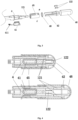
Fig. 1 is the schematic diagram for structure of this invention; -
Fig. 2 is the schematic diagram for internal structure of this invention; -
Fig. 3 is the schematic diagram for structure ofmain bracket 4 in this invention; -
Fig. 4 is the schematic diagram for internal structure ofmain bracket 4 in this invention. - Where:
penholder 1,pen tip 2,charging seat 3,main bracket 4,auxiliary bracket 5,circuit board 6,induction coil 7,shielding layer 8,cartridge assembly 9,battery trough 10,touch induction needle 61,induction part 62, cartridge 91, upper cover ofcartridge 92, lower cover ofcartridge 93,cartridge FPC board 94,shielding tube 95,charging seat 41,guide rail part 42, magnet a43, magnet b44, protectingcrust 45,crust cap 46,iron block 11,magnet set 12. - In order to further illustrate each example, this invention provides patent drawings, which are a part of the contents disclosed in this invention, they are mainly used for illustrating the example, and they can match with relevant description in the specification to explain the operation principle of example, by referencing those contents through matching, ordinary technical personnel of this domain should be capable of understanding other possible modes of carrying out and the advantages of this invention, the assemblies in drawings are not drawn in proportion, and similar assembly symbols are usually used for showing similar assemblies.
- According to the examples of this invention, a kind of active capacitive pen with magnetic rail cap is provided.
- Combined with the patent drawing and description of the preferred embodiments, this invention is further illustrated, as shown in
Fig. 1-4 , according to a kind of active capacitive pen with magnetic rail cap in the example of this invention, it includespenholder 1, the material ofpenholder 1 is plastic or other nonmetallic or non-conductive material, there ispen tip 2 at end of the saidpenholder 1, there is chargingseat 3 at the other end of thepenholder 1 that is far from thepen tip 2, there aremain bracket 4 andauxiliary bracket 5 in thepenholder 1, acircuit board 6 is fixed at the middle segment of themain bracket 4 to match with theauxiliary bracket 5, one end of thecircuit board 6 is linked with thecharging seat 3, the other end of thecircuit board 6 is linked withbattery trough 10, which is mounted on themain bracket 4, there isinduction coil 7 on thecircuit board 6 that is close to themain bracket 4, there is magnet trough at that position that is close to theinduction coil 7,magnet set 12 is installed in the magnet trough, there istouch induction needle 61 on thecircuit board 6, there isinduction part 62 at the position that corresponds to thetouch induction needle 61, and there isshielding layer 8 outside themain bracket 4 andauxiliary bracket 5. - As shown in
Fig.2 , it is a kind of optimal embodiment of this invention, there iscartridge assembly 9 in the saidpen tip 2, the saidcartridge assembly 9 includes cartridge 91, upper cover ofcartridge 92, lower cover ofcartridge 93 andcartridge FPC board 94, the said lower cover ofcartridge 93 is set at the front end of themain bracket 4, the upper cover ofcartridge 92 and lower cover ofcartridge 93 are linked by matching to fix the cartridge 91, and the line pins on the saidcartridge FPC board 94 are all electrically connected with the ground wire, first level signal line and second level signal line. Such an active capacitive pen is charged by magnetic wireless charging, the technical requirements for charging by adsorption on IPAD is simplified, its factory cost is greatly lowered, and more options are offered to users, and there isshielding tube 95 fixed to the upper cover ofcartridge 92 and lower cover ofcartridge 93 through thread. - As shown in
Fig.2 ,Fig.3 and Fig.4 , it is a kind of optimal embodiment of this invention, there are chargingseat 41,guide rail part 42 and protectingcrust 45 at the tail of the saidmain bracket 4, the saidcharging seat 41 is interspersed to be fixed into the installation trough of themain bracket 4, there is tailstock FPCboard 411 at the saidcharging seat 41, the said tailstock FPCboard 411 is electrically connected with thecircuit board 6 through pin, the said protectingcrust 45 covers onto the terminal exterior of themain bracket 4, the said protectingcrust 45 is fixed to themain bracket 4 through screw, there are two guide rails for the saidguide rail part 42, they penetrate through the hole corresponding to one end of the protectingcrust 45 respectively, and they are hooked with the inner step of the protectingcrust 45 through the barb at the end of theguide rail part 42. - As shown in
Fig.3 and Fig.4 , it is a kind of optimal embodiment of this invention, the saidmagnet set 12 includes magnet a121 and magnet b122, the said magnet a121 is set into the end groove of themain bracket 4, the two saidmagnets b 122 are respectively set into the root of the guide rail part42, and they are located in the same horizontal plane as magnet a121 but their magnetism repels each other. The magnet set that is set facilitates the capacitive pen to be adsorbed onto different equipment. - As shown in
Fig.3 , it is a kind of optimal embodiment of this invention, there is buffer cushion between the protectingcrust 45 andguide rail part 42, andcrust cap 46 covers the exterior of the saidguide rail part 42. - As shown in
Fig.3 , it is a kind of optimal example of this invention, there is battery in the saidbattery trough 10, the battery is electrically connected withcircuit board 6, there is rectangular hole below the saidbattery trough 10, and there isiron block 11 in the rectangular hole. - Working principle: the
charging seat 41 is interspersed to be fixed into the installation trough of themain bracket 4, there is tailstockFPC board 411 at thecharging seat 41, the said tailstock FPCboard 411 is electrically connected with thecircuit board 6 through pin, the said protectingcrust 45 covers onto the terminal exterior of themain bracket 4, the protectingcrust 45 is fixed to themain bracket 4 through screw, there are two guide rails for the saidguide rail part 42, they penetrate through the hole corresponding to one end of the protectingcrust 45 respectively, and they are hooked with the inner step of the protectingcrust 45 through the barb at the end of theguide rail part 42. It realizes covering the charging port while effectively taking into consideration the appearance, magnetic slide rail is adopted, it has the advantage of greatly improving the operating feel, and it further solves the problems of exposed charging port being not so good-looking, simple covering being inappropriate, separated cap being prone to loss and the experience of pulling feel being poor. - Except separately and explicitly stipulated and restricted, the terminologies in this invention, including "installation", "setting", "connection", "fixing" and "rotary splicing" should be broadly understood, for example, it can be either permanent connection or detachable connection or being an integral whole; it can be either mechanical connection or electrical connection; it can be either direct connection or indirect connection through intermediate medium, it can be either the connection inside two elements or mutual interactive relationship between two elements, and except separately and explicitly restricted, for ordinary technical personnel in this domain, concrete meaning of the above terminologies in this invention can be understood according to concrete circumstances.
- The above are only relatively good example of this invention, they are not used for restricting this invention, and any modification, equivalent substitution and improvement (etc.) made within the spirit and principle of this invention should all be included in the scope of protection of this invention.
Claims (7)
- An active capacitive pen with magnetic rail cap, comprising a penholder (1), and there is pen tip (2) at the end of the said penholder(1), which is characterized by: there is charging seat (3) at the other end of the penholder (1) that is far from the pen tip (2), there are main bracket (4) and auxiliary bracket (5) in the said penholder (1), a circuit board (6) is fixed at the middle segment of the main bracket (4) to match with the auxiliary bracket (5), one end of the circuit board (6) is linked with the charging seat (3), there are charging seat (41), guide rail part (42) and protecting crust (45) at the tail of the said main bracket (4), the said charging seat (41) is interspersed to be fixed into the installation trough of the main bracket (4), there is tailstock FPC board (411) at the said charging seat (41), the said tailstock FPC board (411) is electrically connected with the circuit board (6) through pin, the said protecting crust (45) covers onto the terminal exterior of the main bracket (4), the said protecting crust (45) is fixed to the main bracket (4) through screw, there are two guide rails for the said guide rail part (42), they penetrates through the hole corresponding to one end of the protecting crust (45) respectively, and they are hooked with the inner step of the protecting crust (45) through the barb at the end of the guide rail part (42).
- The active capacitive pen with magnetic rail cap said according to claim 1, characterized in that there is cartridge assembly (9) in the said pen tip (2), the said cartridge assembly (9) includes cartridge (91), upper cover of cartridge (92), lower cover of cartridge (93) and cartridge FPC board (94). The said lower cover of cartridge (93) is set at the front end of main bracket (4), the upper cover of cartridge (92) and lower cover of cartridge (93) are linked by matching to fix the cartridge (91), and the line pins on the said cartridge FPC board (94) are all electrically connected with the ground wire, first level signal line and second level signal line.
- The active capacitive pen with magnetic rail cap said according to claim 2, characterized in that the exteriors of the said upper cover of cartridge (92) and lower cover of cartridge (93) are fixed with shielding tube (95) through thread.
- The active capacitive pen with magnetic rail cap said according to claim 1, characterized in that the other end of the said circuit board (6) is connected with battery trough (10), which (10) is mounted onto the main bracket (4), there is induction coil (7) for the said circuit board (6) where is close to the main bracket, there is magnet trough at the position where is close to the induction coil (7), magnet set (12) is mounted in the magnet trough, there is touch induction needle (61) on the circuit board (6), there is induction part (62) at that position corresponding to the said touch induction needle (61), and there is shielding layer (8) at the exterior of the said main bracket (4) and auxiliary bracket (5).
- The active capacitive pen with magnetic rail cap said according to claim 4, characterized in that the said magnet set (12) includes magnet a(121) and magnet b(122), the said magnet a(121) is set into the end groove of the main bracket (4), the two said magnets b(122) are respectively set into the root of the guide rail part(42), and they are located in the same horizontal plane as magnet a(121) but their magnetism repels each other.
- The active capacitive pen with magnetic rail cap said according to claim 1, characterized in that there is buffer cushion between the protecting crust (45) and guide rail part (42), and crust cap (46) covers the exterior of the said guide rail part (42).
- The active capacitive pen with magnetic rail cap said according to claim 4, characterized in that there is battery in the said battery trough (10), there is rectangular hole below the said battery trough (10) and there is iron block (11) in the rectangular hole.
Applications Claiming Priority (1)
| Application Number | Priority Date | Filing Date | Title |
|---|---|---|---|
| CN202311774822.0A CN118170266A (en) | 2023-11-28 | 2023-12-21 | Active capacitive stylus with magnetic track cap |
Publications (1)
| Publication Number | Publication Date |
|---|---|
| EP4575731A1 true EP4575731A1 (en) | 2025-06-25 |
Family
ID=89618918
Family Applications (1)
| Application Number | Title | Priority Date | Filing Date |
|---|---|---|---|
| EP24151264.9A Pending EP4575731A1 (en) | 2023-12-21 | 2024-01-11 | Active capacitive pen with magnetic rail cap |
Country Status (4)
| Country | Link |
|---|---|
| US (1) | US20250208723A1 (en) |
| EP (1) | EP4575731A1 (en) |
| JP (1) | JP7631631B1 (en) |
| GB (1) | GB2636879A (en) |
Citations (3)
| Publication number | Priority date | Publication date | Assignee | Title |
|---|---|---|---|---|
| US20180188833A1 (en) * | 2017-01-03 | 2018-07-05 | Griffin Technology, Llc | Protective sleeve for touchscreen stylus |
| US20190278389A1 (en) * | 2018-03-07 | 2019-09-12 | Jing Mold Electronics Technology (Shenzhen) Co., Ltd. | Capacitive Touch Pen |
| US20210255716A1 (en) * | 2020-08-13 | 2021-08-19 | Shenzhen Jinji Digital Technology Co.,Ltd | Intelligent stylus with battery level indicator |
Family Cites Families (13)
| Publication number | Priority date | Publication date | Assignee | Title |
|---|---|---|---|---|
| TWM512740U (en) | 2015-05-01 | 2015-11-21 | Waltop Int Corp | Charging type capacitance touch pen |
| US10168804B2 (en) | 2015-09-08 | 2019-01-01 | Apple Inc. | Stylus for electronic devices |
| TWM517858U (en) | 2015-09-16 | 2016-02-21 | Waltop Int Corp | Portable electronic device and miniaturized charging type capacitor touch pen thereof |
| TWI771371B (en) * | 2017-04-27 | 2022-07-21 | 日商和冠股份有限公司 | rechargeable electronic pen |
| JP7074473B2 (en) | 2017-12-26 | 2022-05-24 | 株式会社ワコム | Electronic pen |
| JP7412058B2 (en) * | 2019-03-13 | 2024-01-12 | 株式会社ワコム | Adapter attached to the electronic pen body |
| CN210246354U (en) * | 2019-08-01 | 2020-04-03 | 深圳市千分一智能技术有限公司 | Protective structure and touch-control pen of mouth charge |
| CN210691275U (en) | 2019-12-30 | 2020-06-05 | 深圳市千分一智能技术有限公司 | Touch control pen |
| CN210864654U (en) * | 2020-01-09 | 2020-06-26 | 黄凤波 | Magnetic slip cap module of active capacitance pen |
| CN212219712U (en) | 2020-01-23 | 2020-12-25 | 深圳市柔宇科技有限公司 | Note book |
| CN215450140U (en) * | 2021-08-10 | 2022-01-07 | 迎客松笔业科技研发中心深圳有限公司 | Active capacitance pen with sliding hidden charging port |
| CN215450139U (en) * | 2021-08-10 | 2022-01-07 | 迎客松笔业科技研发中心深圳有限公司 | Active capacitance pen with sliding hidden charging port |
| US11609648B1 (en) * | 2021-10-29 | 2023-03-21 | Chicony Electronics Co., Ltd. | Stylus pen |
-
2024
- 2024-01-10 US US18/409,416 patent/US20250208723A1/en active Pending
- 2024-01-10 GB GB2400369.1A patent/GB2636879A/en active Pending
- 2024-01-10 JP JP2024001596A patent/JP7631631B1/en active Active
- 2024-01-11 EP EP24151264.9A patent/EP4575731A1/en active Pending
Patent Citations (3)
| Publication number | Priority date | Publication date | Assignee | Title |
|---|---|---|---|---|
| US20180188833A1 (en) * | 2017-01-03 | 2018-07-05 | Griffin Technology, Llc | Protective sleeve for touchscreen stylus |
| US20190278389A1 (en) * | 2018-03-07 | 2019-09-12 | Jing Mold Electronics Technology (Shenzhen) Co., Ltd. | Capacitive Touch Pen |
| US20210255716A1 (en) * | 2020-08-13 | 2021-08-19 | Shenzhen Jinji Digital Technology Co.,Ltd | Intelligent stylus with battery level indicator |
Also Published As
| Publication number | Publication date |
|---|---|
| GB2636879A (en) | 2025-07-02 |
| JP2025100266A (en) | 2025-07-03 |
| JP7631631B1 (en) | 2025-02-19 |
| GB202400369D0 (en) | 2024-02-21 |
| US20250208723A1 (en) | 2025-06-26 |
Similar Documents
| Publication | Publication Date | Title |
|---|---|---|
| RU2672134C2 (en) | Portable terminal and method for providing haptic effect for input unit | |
| CN212966102U (en) | A smart stylus with a battery indicator | |
| EP4575731A1 (en) | Active capacitive pen with magnetic rail cap | |
| CN109271050A (en) | A kind of flexible display panels and flexible display apparatus | |
| CN105677064B (en) | capacitance pen | |
| CN107515685A (en) | Stylus and electronic equipment package with touch function | |
| CN106020567B (en) | The infrared electronic white board system controlled by Intelligent penholder and multifunctional intellectual interaction pen | |
| CN208954061U (en) | Touch screen and display device | |
| CN206236030U (en) | A kind of active capacitive touch pen | |
| CN201294509Y (en) | Touch-sensitive button controlling means | |
| CN118170266A (en) | Active capacitive stylus with magnetic track cap | |
| CN210091124U (en) | Touch control pen | |
| CN206532258U (en) | A kind of active capacitive touch pen | |
| CN214202341U (en) | Capacitive touch screen with knob | |
| CN106502471B (en) | Handwriting drawing screen | |
| CN204578969U (en) | Multi-level electromagnetic shielding system | |
| CN212569716U (en) | Portable telescopic plate capacitance pen | |
| CN204595792U (en) | Condenser type computer drawing pen external member | |
| CN204178270U (en) | The writing function Multimedia System of meeting teaching band | |
| CN203574771U (en) | Touching-type television and computer combined machine | |
| CN104965610A (en) | Page turner | |
| CN210924534U (en) | Suspension touch control touch screen | |
| CN209708095U (en) | Hand-written electric structure | |
| CN208511852U (en) | A kind of hand trip auxiliary touch screen device | |
| CN207218527U (en) | A kind of circuit for improving Switching Power Supply interference AM receiver |
Legal Events
| Date | Code | Title | Description |
|---|---|---|---|
| STAA | Information on the status of an ep patent application or granted ep patent |
Free format text: STATUS: UNKNOWN |
|
| PUAI | Public reference made under article 153(3) epc to a published international application that has entered the european phase |
Free format text: ORIGINAL CODE: 0009012 |
|
| STAA | Information on the status of an ep patent application or granted ep patent |
Free format text: STATUS: THE APPLICATION HAS BEEN PUBLISHED |
|
| AK | Designated contracting states |
Kind code of ref document: A1 Designated state(s): AL AT BE BG CH CY CZ DE DK EE ES FI FR GB GR HR HU IE IS IT LI LT LU LV MC ME MK MT NL NO PL PT RO RS SE SI SK SM TR |