EP4575655A1 - Feeding device and image forming system including same - Google Patents
Feeding device and image forming system including same Download PDFInfo
- Publication number
- EP4575655A1 EP4575655A1 EP24219759.8A EP24219759A EP4575655A1 EP 4575655 A1 EP4575655 A1 EP 4575655A1 EP 24219759 A EP24219759 A EP 24219759A EP 4575655 A1 EP4575655 A1 EP 4575655A1
- Authority
- EP
- European Patent Office
- Prior art keywords
- feeding
- control unit
- sheet
- heater
- fan
- Prior art date
- Legal status (The legal status is an assumption and is not a legal conclusion. Google has not performed a legal analysis and makes no representation as to the accuracy of the status listed.)
- Pending
Links
Images



Classifications
-
- G—PHYSICS
- G03—PHOTOGRAPHY; CINEMATOGRAPHY; ANALOGOUS TECHNIQUES USING WAVES OTHER THAN OPTICAL WAVES; ELECTROGRAPHY; HOLOGRAPHY
- G03G—ELECTROGRAPHY; ELECTROPHOTOGRAPHY; MAGNETOGRAPHY
- G03G21/00—Arrangements not provided for by groups G03G13/00 - G03G19/00, e.g. cleaning, elimination of residual charge
- G03G21/20—Humidity or temperature control also ozone evacuation; Internal apparatus environment control
-
- B—PERFORMING OPERATIONS; TRANSPORTING
- B65—CONVEYING; PACKING; STORING; HANDLING THIN OR FILAMENTARY MATERIAL
- B65H—HANDLING THIN OR FILAMENTARY MATERIAL, e.g. SHEETS, WEBS, CABLES
- B65H1/00—Supports or magazines for piles from which articles are to be separated
- B65H1/04—Supports or magazines for piles from which articles are to be separated adapted to support articles substantially horizontally, e.g. for separation from top of pile
-
- B—PERFORMING OPERATIONS; TRANSPORTING
- B65—CONVEYING; PACKING; STORING; HANDLING THIN OR FILAMENTARY MATERIAL
- B65H—HANDLING THIN OR FILAMENTARY MATERIAL, e.g. SHEETS, WEBS, CABLES
- B65H3/00—Separating articles from piles
- B65H3/46—Supplementary devices or measures to assist separation or prevent double feed
- B65H3/48—Air blast acting on edges of, or under, articles
-
- G—PHYSICS
- G03—PHOTOGRAPHY; CINEMATOGRAPHY; ANALOGOUS TECHNIQUES USING WAVES OTHER THAN OPTICAL WAVES; ELECTROGRAPHY; HOLOGRAPHY
- G03G—ELECTROGRAPHY; ELECTROPHOTOGRAPHY; MAGNETOGRAPHY
- G03G21/00—Arrangements not provided for by groups G03G13/00 - G03G19/00, e.g. cleaning, elimination of residual charge
- G03G21/20—Humidity or temperature control also ozone evacuation; Internal apparatus environment control
- G03G21/203—Humidity
-
- G—PHYSICS
- G03—PHOTOGRAPHY; CINEMATOGRAPHY; ANALOGOUS TECHNIQUES USING WAVES OTHER THAN OPTICAL WAVES; ELECTROGRAPHY; HOLOGRAPHY
- G03G—ELECTROGRAPHY; ELECTROPHOTOGRAPHY; MAGNETOGRAPHY
- G03G21/00—Arrangements not provided for by groups G03G13/00 - G03G19/00, e.g. cleaning, elimination of residual charge
- G03G21/20—Humidity or temperature control also ozone evacuation; Internal apparatus environment control
- G03G21/206—Conducting air through the machine, e.g. for cooling, filtering, removing gases like ozone
-
- B—PERFORMING OPERATIONS; TRANSPORTING
- B41—PRINTING; LINING MACHINES; TYPEWRITERS; STAMPS
- B41J—TYPEWRITERS; SELECTIVE PRINTING MECHANISMS, i.e. MECHANISMS PRINTING OTHERWISE THAN FROM A FORME; CORRECTION OF TYPOGRAPHICAL ERRORS
- B41J11/00—Devices or arrangements of selective printing mechanisms, e.g. ink-jet printers or thermal printers, for supporting or handling copy material in sheet or web form
- B41J11/0015—Devices or arrangements of selective printing mechanisms, e.g. ink-jet printers or thermal printers, for supporting or handling copy material in sheet or web form for treating before, during or after printing or for uniform coating or laminating the copy material before or after printing
-
- B—PERFORMING OPERATIONS; TRANSPORTING
- B41—PRINTING; LINING MACHINES; TYPEWRITERS; STAMPS
- B41J—TYPEWRITERS; SELECTIVE PRINTING MECHANISMS, i.e. MECHANISMS PRINTING OTHERWISE THAN FROM A FORME; CORRECTION OF TYPOGRAPHICAL ERRORS
- B41J13/00—Devices or arrangements of selective printing mechanisms, e.g. ink-jet printers or thermal printers, specially adapted for supporting or handling copy material in short lengths, e.g. sheets
- B41J13/0009—Devices or arrangements of selective printing mechanisms, e.g. ink-jet printers or thermal printers, specially adapted for supporting or handling copy material in short lengths, e.g. sheets control of the transport of the copy material
- B41J13/0018—Devices or arrangements of selective printing mechanisms, e.g. ink-jet printers or thermal printers, specially adapted for supporting or handling copy material in short lengths, e.g. sheets control of the transport of the copy material in the sheet input section of automatic paper handling systems
-
- B—PERFORMING OPERATIONS; TRANSPORTING
- B65—CONVEYING; PACKING; STORING; HANDLING THIN OR FILAMENTARY MATERIAL
- B65H—HANDLING THIN OR FILAMENTARY MATERIAL, e.g. SHEETS, WEBS, CABLES
- B65H2220/00—Function indicators
- B65H2220/01—Function indicators indicating an entity as a function of which control, adjustment or change is performed, i.e. input
-
- B—PERFORMING OPERATIONS; TRANSPORTING
- B65—CONVEYING; PACKING; STORING; HANDLING THIN OR FILAMENTARY MATERIAL
- B65H—HANDLING THIN OR FILAMENTARY MATERIAL, e.g. SHEETS, WEBS, CABLES
- B65H2220/00—Function indicators
- B65H2220/02—Function indicators indicating an entity which is controlled, adjusted or changed by a control process, i.e. output
-
- B—PERFORMING OPERATIONS; TRANSPORTING
- B65—CONVEYING; PACKING; STORING; HANDLING THIN OR FILAMENTARY MATERIAL
- B65H—HANDLING THIN OR FILAMENTARY MATERIAL, e.g. SHEETS, WEBS, CABLES
- B65H2515/00—Physical entities not provided for in groups B65H2511/00 or B65H2513/00
- B65H2515/20—Volume; Volume flow
-
- B—PERFORMING OPERATIONS; TRANSPORTING
- B65—CONVEYING; PACKING; STORING; HANDLING THIN OR FILAMENTARY MATERIAL
- B65H—HANDLING THIN OR FILAMENTARY MATERIAL, e.g. SHEETS, WEBS, CABLES
- B65H2515/00—Physical entities not provided for in groups B65H2511/00 or B65H2513/00
- B65H2515/40—Temperature; Thermal conductivity
-
- B—PERFORMING OPERATIONS; TRANSPORTING
- B65—CONVEYING; PACKING; STORING; HANDLING THIN OR FILAMENTARY MATERIAL
- B65H—HANDLING THIN OR FILAMENTARY MATERIAL, e.g. SHEETS, WEBS, CABLES
- B65H2515/00—Physical entities not provided for in groups B65H2511/00 or B65H2513/00
- B65H2515/805—Humidity
-
- B—PERFORMING OPERATIONS; TRANSPORTING
- B65—CONVEYING; PACKING; STORING; HANDLING THIN OR FILAMENTARY MATERIAL
- B65H—HANDLING THIN OR FILAMENTARY MATERIAL, e.g. SHEETS, WEBS, CABLES
- B65H2801/00—Application field
- B65H2801/03—Image reproduction devices
- B65H2801/12—Single-function printing machines, typically table-top machines
Definitions
- the present disclosure relates to a feeding device and an image forming system which includes such a feeding device.
- sheets are fed one by one from a bundle of a plurality of sheets which are set.
- the image forming apparatus prints an image on the sheet which is fed.
- the sheets are coated paper
- the sheets which are set are difficult to separate from each other. If the set sheets are not separated from each other, simultaneous feeding disadvantageously occurs when the sheet is fed.
- control unit When the control unit receives a feeding start command from a feeding destination of the sheet, if the sheet to be fed by the feeding unit is coated paper, the control unit recognizes an internal environment of the feeding device based on an output of the temperature and humidity sensor and performs condition determination processing to determine whether the internal environment satisfies a predetermined condition. When the control unit determines that the predetermined condition is satisfied in the condition determination processing, the control unit starts driving of the fan and the heater and then causes the feeding unit to start the feeding of the sheet. When the feeding of the sheet in a state where the fan and the heater are driven is completed, the control unit stops the driving of the heater and continues the driving of the fan regardless of whether the internal environment satisfies the predetermined condition.
- a feeding device 100 according to an embodiment of the present disclosure and an image forming system 100S which includes the feeding device 100 will be described below with reference to FIGS. 1 to 10 .
- the feeding device 100 is placed on a floor surface together with the image forming apparatus 1000.
- a direction perpendicular to the floor surface (flat surface) on which the feeding device 100 is placed is the up/down direction of the feeding device 100.
- the feeding device 100 may be removable with respect to the image forming apparatus 1000.
- the feeding device 100 is, for example, an optional device.
- the feeding device 100 when viewed from the front of the image forming apparatus 1000 is arranged on the right side of the image forming apparatus 1000.
- the feeding direction Df is one direction of horizontal directions orthogonal to the up/down direction.
- a direction which is horizontally orthogonal to the feeding direction Df corresponds to the width direction of the feeding device 100.
- the width direction of the feeding device 100 is identified with a symbol Dw.
- the width direction Dw is also the forward/backward direction of the feeding device 100.
- the image forming apparatus 1000 prints an image on the sheet S fed from the feeding device 100.
- the printing system of the image forming apparatus 1000 is an electrophotographic system.
- the printing system of the image forming apparatus 1000 may be an inkjet system.
- the image forming apparatus 1000 coveys the sheet S fed from the feeding device 100 along a conveyance path.
- the image forming apparatus 1000 prints the image on the sheet S being conveyed.
- the conveyance path of the sheet S is represented by an arrow with dashed lines.
- the image forming apparatus 1000 includes a photosensitive drum 1001 and a transfer roller 1002.
- the photosensitive drum 1001 carries a toner image on its circumferential surface.
- the transfer roller 1002 is pressed against the photosensitive drum 1001 to form a transfer nip between itself and the photosensitive drum 1001.
- the transfer roller 1002 is rotated together with the photosensitive drum 1001.
- the sheet S being conveyed enters the transfer nip, and thus transfer processing is performed on the sheet S, with the result that the toner image is transferred to the sheet S.
- the feeding device 100 includes, as a sheet storage region, a region between the front frame Ff and the rear frame Fr in the width direction Dw.
- the sheet storage region is covered by an upper surface cover CV (see FIGS. 1 and 2 ) from above.
- the feeding device 100 includes the upper surface cover CV.
- the upper surface cover CV corresponds to a "cover".
- Each of the winding drums 21 is supported rotatably around the same axis line extending in the width direction Dw.
- the winding drums 21 are attached to the same rotation shaft 210, and are rotated together with the rotation shaft 210.
- the rotation shaft 210 is coupled to an unillustrated winding motor, and the winding motor is driven to rotate the rotation shaft 210.
- Each of the winding drums 21 is rotated in forward and reverse directions to wind and unwind the wire 20. In other words, the set plate 1 is raised and lowered.
- the pickup roller 31 is rotatably supported. In a state where the sheet S is set on the set plate 1, the pickup roller 31 is arranged in such a position that the pickup roller 31 can make contact with a downstream side end portion of the sheet S in the feeding direction Df from above. The pickup roller 31 makes contact with the sheet S set on the set plate 1 from above, and is rotated in this state to pull out the sheet S from the set plate 1.
- the conveyance roller pair 32 is rotatably supported.
- the conveyance roller pair 32 is a pair of rollers which are pressed against each other.
- the conveyance roller pair 32 is arranged on the downstream side in the feeding direction Df with respect to the pickup roller 31.
- the conveyance roller pair 32 nips the sheet S pulled out from the set plate 1 by the pickup roller 31, and is rotated. In this way, the conveyance roller pair 32 conveys the sheet S toward the image forming apparatus 1000.
- the number of conveyance roller pairs 32 which are installed is not particularly limited, and can be changed according to, for example, the length of the conveyance path for the sheet S from the pickup roller 31 to the image forming apparatus 1000.
- the raising/lowering mechanism 2 raises the set plate 1 to cause the sheet S in the uppermost layer on the set plate 1 to make contact with the pickup roller 31.
- the raising/lowering mechanism 2 raises the set plate 1 and stops the raising repeatedly. In this way, the contact of the sheet S in the uppermost layer on the set plate 1 with the pickup roller 31 is maintained.
- the feeding device 100 includes width-direction restriction cursors 4 and 5.
- the width-direction restriction cursors 4 and 5 are supported to be able to reciprocate in the width direction Dw.
- the width-direction restriction cursors 4 and 5 are arranged opposite each other in the width direction Dw with a distance provided therebetween. The user performs an operation, and thus the width-direction restriction cursors 4 and 5 are moved in the width direction Dw.
- the width-direction restriction cursors 4 and 5 are moved in the width direction Dw in conjunction with each other.
- the width-direction restriction cursor 4 is moved backward, the width-direction restriction cursor 4 is moved forward, and thus the distance between the width-direction restriction cursors 4 and 5 in the width direction Dw is decreased.
- the width-direction restriction cursor 4 is moved forward, the width-direction restriction cursor 5 is moved backward, and thus the distance between the width-direction restriction cursors 4 and 5 in the width direction Dw is increased.
- the width-direction restriction cursors 4 and 5 are moved in the width direction Dw to make contact with end edges of the sheet S on the set plate 1 in the width direction Dw.
- the width-direction restriction cursor 4 is moved from forward to backward to make contact with the end edge of the sheet S on the set plate 1 from forward.
- the width-direction restriction cursor 5 is moved from backward to forward to make contact with the end edge of the sheet S on the set plate 1 from backward. In this way, the width-direction restriction cursors 4 and 5 restrict a displacement of the sheet S on the set plate 1 in the width direction Dw.
- the feeding device 100 further includes a rear end restriction cursor RC.
- the rear end restriction cursor RC is supported to be able to reciprocate in the left/right direction. The user performs an operation, and thus the rear end restriction cursor RC is moved in the left/right direction.
- the rear end restriction cursor RC is moved from the upstream side to the downstream side in the feeding direction Df to make contact with the back end edge of the sheet S on the set plate 1. In this way, the rear end restriction cursor RC restricts a displacement of the sheet S on the set plate 1 to the upstream side in the feeding direction Df.
- the set plate 1 When the set plate 1 is viewed from above, the set plate 1 includes an opening (the symbol of which is omitted) on the movement paths of the width-direction restriction cursors 4 and 5, and also includes an opening (the symbol of which is omitted) on the movement path of the rear end restriction cursor RC. Hence, even when the width-direction restriction cursors 4 and 5 are moved in the width direction Dw, the width-direction restriction cursors 4 and 5 do not make contact with the set plate 1. Even when the rear end restriction cursor RC is moved in the left/right direction, the rear end restriction cursor RC does not make contact with the set plate 1.
- the set plate 1 when the set plate 1 is viewed from above, even if the sheet S is smaller than the set plate 1, the width-direction restriction cursors 4 and 5 can be brought into contact with the end edges of the sheet S without making contact with the set plate 1, and the rear end restriction cursor RC can be brought into contact with the end edge of the sheet S without making contact with the set plate 1.
- the set plate 1 is hatched.
- the feeding device 100 includes a dehumidification unit D.
- the dehumidification unit D blows heated air to the sheet storage region on the set plate 1.
- the dehumidification unit D applies the hot air to the sheets S on the set plate 1.
- the dehumidification unit D performs dehumidification for the sheets S on the set plate 1.
- the dehumidification unit D includes a fan 6 and a heater 7.
- the fan 6 is driven to blow the air to the sheets S on the set plate 1.
- the heater 7 is arranged on the path of an airflow generated by the fan 6. The heater 7 heats the air to be blown to the sheets S on the set plate 1. In this way, the fan 6 and the heater 7 are driven to apply the hot air to the sheets S on the set plate 1, and thus dehumidification is performed for the sheets S on the set plate 1.
- the fan 6 and the heater 7 are arranged in the width-direction restriction cursor 5 on the back side.
- the width-direction restriction cursor 5 corresponds to a " restriction cursor”.
- the fan 6 and the heater 7 are arranged outward of the width-direction restriction cursor 5 in the width direction Dw.
- the "outward" of the width-direction restriction cursor 5 in the width direction Dw refers to the opposite side of the width-direction restriction cursor 5 (that is, the back side of the width-direction restriction cursor 5) to the side of the sheet storage region in the width direction Dw.
- a vent 50 which penetrates in the width direction Dw is formed.
- the hot air generated by the fan 6 and the heater 7 flows to the sheet storage region on the set plate 1 via the vent 50.
- the number of fans 6 are two.
- the two fans 6 are arranged along the feeding direction Df.
- the number of heaters 7 is one.
- the one heater 7 is assigned to the fan 6 of the two fans 6 located on the downstream side in the feeding direction Df.
- the one fan 6 heats the air to be blown by the fan 6 of the two fans 6 located on the downstream side in the feeding direction Df.
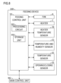
- the feeding device 100 includes a feeding control unit 10.
- the feeding control unit 10 corresponds to a "control unit”.
- the feeding control unit 10 includes a processing circuit 101 of a CPU, an ASIC and the like.
- the feeding control unit 10 includes a storage unit 102 of a ROM, a RAM, a HDD, an SSD and the like.
- the feeding control unit 10 is connected to a main control unit MC in the image forming apparatus 1000.
- the feeding control unit 10 communicates with the main control unit MC.
- the main control unit MC receives, from the user, a job setting related to a job for feeding the sheet S with the feeding device 100 (hereinafter simply referred to as the job).
- the job For example, in the image forming apparatus 1000, an operation panel (not shown) is provided, and the operation panel receives the job setting from the user.
- the main control unit MC recognizes the details of the job setting received by the operation panel.
- the main control unit MC transmits, to the feeding control unit 10, a control instruction based on the job setting indicated by the user.
- the feeding control unit 10 controls, based on the control instruction from the main control unit MC, processing for feeding the sheet S with the feeding device 100 (in other words, processing for feeding the sheet S from the feeding device 100 to the image forming apparatus 1000).
- the main control unit MC transmits a feeding start command for the sheet S to the feeding control unit 10.
- the feeding control unit 10 receives the feeding start command from the image forming apparatus 1000 which is the feeding destination of the sheet S.
- the feeding control unit 10 causes the feeding unit 3 to start the feeding of the sheet S.
- the feeding control unit 10 rotates the rotation member (the pickup roller 31 and the conveyance roller pair 32) of the feeding unit 3.
- the feeding control unit 10 raises the set plate 1 to cause the sheet S in the uppermost layer on the set plate 1 to make contact with the pickup roller 31. In this way, the sheet S on the set plate 1 is fed to the image forming apparatus 1000.
- the feeding control unit 10 controls dehumidification processing for the sheets S performed by the dehumidification unit D. In other words, the feeding control unit 10 controls the driving of the fan 6. The feeding control unit 10 controls the driving of the heater 7. The dehumidification processing for the sheets S performed by the dehumidification unit D will be described in detail later.
- the feeding device 100 includes a temperature sensor 12.
- the temperature sensor 12 detects an external temperature of the feeding device 100.
- the temperature sensor 12 is connected to the feeding control unit 10.
- the feeding control unit 10 detects the external temperature of the feeding device 100 based on the output of the temperature sensor 12.
- an outside air temperature detection sensor is provided in the image forming apparatus 1000, and the outside air temperature detection sensor is connected to the main control unit MC.
- the temperature sensor 12 may be omitted, and the main control unit MC may transmit information indicating an outside air temperature (that is, the external temperature of the feeding device 100) to the feeding control unit 10.
- the feeding device 100 includes an opening/closing sensor 13.
- the opening/closing sensor 13 outputs a value corresponding to the opened/closed state of the upper surface cover CV. For example, when the upper surface cover CV is opened, the output value of the opening/closing sensor 13 is changed.
- the opening/closing sensor 13 is connected to the feeding control unit 10.
- the feeding control unit 10 detects, based on the output of the opening/closing sensor 13, that the upper surface cover CV has been opened and that the upper surface cover CV has been closed.
- the feeding device 100 includes a heater temperature sensor 70 (for example, a thermistor).
- the heater temperature sensor 70 detects the temperature of the heater 7.
- the heater temperature sensor 70 is connected to the feeding control unit 10.
- the feeding control unit 10 detects the temperature of the heater 7 based on the output of the heater temperature sensor 70.
- Various types of sheets S are used in the job.
- coated paper may be used.
- the sheet S used in the job is the coated paper, depending on the internal temperature and the internal humidity of the feeding device 100, the wetness of the sheets S is increased, and thus the sheets S stacked on the set plate 1 are difficult to separate from each other. In this way, when the sheet S on the set plate 1 is fed, simultaneous feeding in which a plurality of sheets S are fed together easily occurs.
- the dehumidification unit D is provided in the feeding device 100.
- the dehumidification unit D performs dehumidification for the sheets S on the set plate 1. In this way, the simultaneous feeding of the sheets S is suppressed.
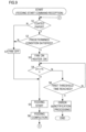
- the feeding control unit 10 When the feeding control unit 10 receives a feeding start command from the feeding destination of the sheet S (that is, the image forming apparatus 1000), the flow shown in FIG. 9 is started. At the start of the flow shown in FIG. 9 , the fan 6 may be driven or the fan 6 may not be driven. On the other hand, the heater 7 is not driven.
- the feeding control unit 10 determines an absolute humidity based on the output of the temperature and humidity sensor 11.
- the feeding control unit 10 acquires the absolute humidity based on the output of the temperature and humidity sensor 11 as the internal environment of the feeding device 100.
- the feeding control unit 10 performs, as the condition determination processing, processing for determining that the predetermined condition is satisfied when the absolute humidity based on the output of the temperature and humidity sensor 11 is higher than a threshold humidity.
- the feeding control unit 10 determines that the predetermined condition is not satisfied when the absolute humidity based on the output of the temperature and humidity sensor 11 is equal to or less than the threshold humidity.
- the condition determination processing is processing for determining whether the simultaneous feeding of the sheets S easily occurs.
- a state where the simultaneous feeding of the sheets S easily occurs refers to a state where the absolute humidity based on the output of the temperature and humidity sensor 11 is higher than the threshold humidity.
- step S2 the feeding control unit 10 determines that the predetermined condition is satisfied, the processing transfers to step S3.
- the processing transfers to step S3.
- the processing transfers to step S3.
- step S3 the feeding control unit 10 starts the driving of the fan 6 (fan: on).
- the feeding control unit 10 drives the fan 6 at a predetermined reference rotation speed.
- the feeding control unit 10 performs PWM control to drive the fan 6.
- the feeding control unit 10 also starts the driving of the heater 7 (heater: on).
- the feeding control unit 10 determines that the predetermined condition is satisfied in the condition determination processing, the feeding control unit 10 measures a first elapsed time that is a time which has elapsed since the start of the driving of the heater 7. In other words, when the processing transfers to step S3, the feeding control unit 10 starts the measurement of the first elapsed time.
- step S4 the feeding control unit 10 determines whether the temperature (HT) of the heater 7 is higher than a threshold temperature (Tt).
- Tt a threshold temperature
- the processing transfers to step S5.
- the threshold temperature is a temperature (external temperature + 10°) which is 10 degrees higher than the external temperature of the feeding device 100. In other words, the threshold temperature is changed depending on the external temperature of the feeding device 100.
- step S5 the feeding control unit 10 causes the feeding unit 3 to start the feeding of the sheet S.
- the feeding control unit 10 determines that the predetermined condition is satisfied in the condition determination processing, the feeding control unit 10 starts the driving of the fan 6 and the heater 7, and then causes the feeding unit 3 to start the feeding of the sheet S.
- the feeding control unit 10 causes the feeding unit 3 to feed the sheet S in a state where the upper surface cover CV is closed.
- step S6 the feeding of the sheet S is completed, the feeding control unit 10 stops the feeding operation of the feeding unit 3.
- step S1 the feeding control unit 10 determines that the sheet S to be fed by the feeding unit 3 is not the coated paper, the processing transfers to step S7.
- step S7 the feeding control unit 10 does not drive the fan 6 (fan: off). Thereafter, the processing transfers to step S5.
- step S7 the feeding control unit 10 stops the driving of the fan 6.
- step S7 the driving of the fan 6 is stopped, the feeding control unit 10 maintains the stop of the driving of the fan 6. In any case, when the sheet S to be fed by the feeding unit 3 is not the coated paper, the feeding control unit 10 does not drive the fan 6 and the heater 7.
- step S2 the feeding control unit 10 determines that the predetermined condition is not satisfied, the processing transfers to step S7.
- the feeding control unit 10 determines that the predetermined condition is not satisfied in the condition determination processing, even if the sheet S to be fed by the feeding unit 3 is the coated paper, the feeding control unit 10 does not drive the fan 6 and the heater 7.
- step S4 the feeding control unit 10 determines that the temperature of the heater 7 is equal to or less than the threshold temperature (HT ⁇ Tt), the processing transfers to step S8.
- step S8 the feeding control unit 10 determines whether the first elapsed time has reached a first threshold time. When the feeding control unit 10 determines that the first elapsed time has not reached the first threshold time, the processing transfers to step S4. When the feeding control unit 10 determines that the first elapsed time has reached the first threshold time, the processing transfers to step S9.
- step S9 the feeding control unit 10 performs error notification processing for notifying information indicating that an abnormality occurs in the heater 7. Specifically, when the temperature of the heater 7 reaches the threshold temperature before the first elapsed time reaches the first threshold time, the feeding control unit 10 causes the feeding unit 3 to start the feeding of the sheet S. On the other hand, even when the first elapsed time reaches the first threshold time, if the temperature of the heater 7 does not reach the threshold temperature, the feeding control unit 10 performs the error notification processing.
- the feeding control unit 10 performs, as the error notification processing, processing for transmitting, to the main control unit MC, the information indicating that an abnormality occurs in the heater 7.
- the main control unit MC receives the error notification from the feeding control unit 10, the main control unit MC performs, for example, processing for displaying an error message on the operation panel.
- step S6 When the feeding of the sheet S is completed, the processing transfers from step S6 to step S10 (see FIG. 10 ).
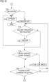
- step S10 the feeding control unit 10 determines whether the fan 6 is driven. That the fan 6 is driven at this point means that the heater 7 is also driven. On the other hand, that the fan 6 is not driven at this point means that the heater 7 is also not driven.
- step S10 the feeding control unit 10 determines that the fan 6 is not driven, the processing transfers to step S11.
- step S11 the feeding control unit 10 is brought into a standby state, and is kept on standby until the reception of a new feeding start command.
- the feeding control unit 10 does not drive the fan 6 and the heater 7.
- the feeding control unit 10 does not drive the heater 7 after the completion of the feeding of the sheet S until the reception of the subsequent feeding start command.
- step S10 the feeding control unit 10 determines that the fan 6 is driven
- the processing transfers to step S12.
- step S12 the feeding control unit 10 stops the driving of the heater 7 (heater: off).
- the feeding control unit 10 stops the driving of the heater 7 regardless of whether the internal environment of the feeding device 100 satisfies the predetermined condition (that is, regardless of whether the absolute humidity based on the temperature and humidity sensor 11 is higher than the threshold humidity).
- the feeding control unit 10 continues the driving of the fan 6. In other words, at this point, the fan 6 is driven in a state where the driving of the heater 7 is stopped.
- the feeding control unit 10 measures a second elapsed time that is a time which has elapsed since the stop of the driving of the heater 7. In other words, when the processing transfers to step S12, the feeding control unit 10 starts the measurement of the second elapsed time.
- step S13 the feeding control unit 10 determines whether the second elapsed time has reached a second threshold time.
- the processing transfers to step S14.
- step S14 the feeding control unit 10 stops the driving of the fan 6 (fan: off). Thereafter, the processing transfers to step S11.
- step S13 the feeding control unit 10 determines that the second elapsed time has not reached the second threshold time
- the processing transfers to step S15.
- step S15 the feeding control unit 10 determines whether the upper surface cover CV has been opened. The feeding control unit 10 detects that the upper surface cover CV has been opened based on the output of the opening/closing sensor 13.
- step S15 the feeding control unit 10 determines that the upper surface cover CV has not been opened, the processing transfers to step S16.
- step S16 the feeding control unit 10 determines whether the subsequent feeding start command (that is, a new feeding start command) has been received from the main control unit MC.
- step S16 the feeding control unit 10 determines that the subsequent feeding start command has been received from the main control unit MC, the processing transfers to step S1 (see FIG. 9 ).
- step S13 the processing transfers to step S13. In other words, when the second elapsed time reaches the second threshold time after the stop of the driving of the heater 7 before the reception of the subsequent feeding start command from the main control unit MC, the feeding control unit 10 stops the driving of the fan 6.
- step S15 the feeding control unit 10 determines that the upper surface cover CV has been opened, the processing transfers to step S17.
- step S17 while the fan 6 is being driven, the feeding control unit 10 switches the rotation speed of the fan 6 to a low speed (fan: low speed).
- the feeding control unit 10 drives the fan 6 at a rotation speed lower than the reference rotation speed which is a rotation speed before the upper surface cover CV has been opened. Thereafter, the processing transfers to step S13.
- the feeding control unit 10 drives the fan 6 at a rotation speed lower than a rotation speed before the upper surface cover CV has been opened.
- the feeding control unit 10 when the feeding control unit 10 determines that the predetermined condition is satisfied in the condition determination processing, the feeding control unit 10 starts the driving of the fan 6 and the heater 7, and then causes the feeding unit 3 to start the feeding of the sheet S. In other words, the feeding control unit 10 causes the feeding unit 3 to start the feeding of the sheet S while performing dehumidification for the sheets S to be fed by the feeding unit 3. In this way, it is possible to suppress the simultaneous feeding of the sheets S.
- the feeding control unit 10 when the feeding control unit 10 receives the feeding start command from the feeding destination of the sheet S, the feeding control unit 10 performs the condition determination processing for determining whether the fan 6 and the heater 7 are driven. Furthermore, when the feeding of the sheet S is completed, the feeding control unit 10 stops the driving of the heater 7 regardless of whether the internal environment of the feeding device 100 satisfies the predetermined condition. In other words, the feeding control unit 10 does not drive the heater 7 at least after the completion of the feeding of the sheet S until the reception of the subsequent feeding start command. In this way, an increase in power consumption caused by increasing the driving time of the heater 7 is suppressed. Consequently, it is possible to suppress the simultaneous feeding of the sheets S while suppressing an increase in power consumption in the feeding device 100.
- the driving of the heater 7 is immediately stopped when the feeding of the sheet S is completed, the driving of the fan 6 is continued. In this way, it is possible to suppress an overshoot in the heater 7.
- the feeding control unit 10 determines that the predetermined condition is satisfied when the absolute humidity is higher than the threshold humidity. In this way, it is possible to easily perform dehumidification in a state where the simultaneous feeding of the sheets S easily occurs.
- the feeding control unit 10 when the sheet S to be fed by the feeding unit 3 is not the coated paper, the feeding control unit 10 does not drive the fan 6 and the heater 7. Furthermore, when the feeding control unit 10 determines that the predetermined condition is not satisfied in the condition determination processing, even if the sheet S to be fed by the feeding unit 3 is the coated paper, the feeding control unit 10 does not drive the fan 6 and the heater 7. In other words, only when the simultaneous feeding of the sheets S easily occurs, the fan 6 and the heater 7 are driven. In this way, it is possible to further suppress power consumption.
- the feeding control unit 10 when the temperature of the heater 7 reaches the threshold temperature before the first elapsed time reaches the first threshold time, the feeding control unit 10 causes the feeding unit 3 to start the feeding of the sheet S. On the other hand, even when the first elapsed time reaches the first threshold time, if the temperature of the heater 7 does not reach the threshold temperature, the feeding control unit 10 performs the processing which notifies an error.
- the processing which notifies an error is preferably performed.
- the feeding control unit 10 stops the driving of the fan 6. In this way, it is possible to suppress unnecessary continuous driving of the fan 6.
- the feeding control unit 10 when as described above, the feeding control unit 10 detects that the upper surface cover CV has been opened based on the output of the opening/closing sensor 13 after the stop of the driving of the heater 7, before the reception of the subsequent feeding start command from the feeding destination of the sheet S and before the second elapsed time reaches the second threshold time, the feeding control unit 10 drives the fan 6 at a rotation speed lower than a rotation speed before the upper surface cover CV has been opened.
- that the upper surface cover CV has been opened indicates that the operation for setting the sheets S on the set plate 1 is performed.
- the operation for setting the sheets S is performed, if an airflow is generated on the set plate 1, workability deteriorates. Hence, the rotation speed of the fan 6 is lowered. In this way, it is possible to suppress a decrease in the workability.
- the fan 6 and the heater 7 are arranged in the width-direction restriction cursor 5. In this way, it is possible to easily apply the hot air to the sheet S.
- the heater 7 is assigned to only the fan 6 located on the downstream side in the feeding direction Df. In this way, it is possible to further suppress power consumption.
- the pickup roller 31 makes contact with the front end side (the downstream side in the feeding direction Df) of the sheets S. In this configuration, when dehumidification for the front end side of the sheets S is not sufficient, the simultaneous feeding of the sheets S easily occurs. Hence, the air which is blown by the fan 6 located on the downstream side in the feeding direction Df is preferably heated.
Landscapes
- Engineering & Computer Science (AREA)
- Life Sciences & Earth Sciences (AREA)
- Atmospheric Sciences (AREA)
- Biodiversity & Conservation Biology (AREA)
- Ecology (AREA)
- Environmental & Geological Engineering (AREA)
- Environmental Sciences (AREA)
- Physics & Mathematics (AREA)
- General Physics & Mathematics (AREA)
- Mechanical Engineering (AREA)
- Sheets, Magazines, And Separation Thereof (AREA)
- Paper Feeding For Electrophotography (AREA)
Abstract
A feeding device (100) includes a set plate (1), a feeding unit (3), a fan (6), a heater (7), a control unit (10) and a temperature and humidity sensor (11). When the control unit (10) receives a feeding start command, if the sheet (S) to be fed by the feeding unit (3) is coated paper, the control unit (10) performs condition determination processing to determine whether an internal environment satisfies a predetermined condition. When the control unit (10) determines that the predetermined condition is satisfied, the control unit (10) starts driving of the fan (6) and the heater (7), and then starts the feeding of the sheet (S). When the feeding of the sheet (S) is completed, the control unit (10) stops the driving of the heater (7) and continues the driving of the fan (6) regardless of whether the internal environment satisfies the predetermined condition.
Description
- The present disclosure relates to a feeding device and an image forming system which includes such a feeding device.
- When printing is performed in an image forming apparatus, sheets are fed one by one from a bundle of a plurality of sheets which are set. The image forming apparatus prints an image on the sheet which is fed.
- Here, there are various types of sheets. For example, when the sheets are coated paper, the sheets which are set are difficult to separate from each other. If the set sheets are not separated from each other, simultaneous feeding disadvantageously occurs when the sheet is fed.
- Hence, some conventional image forming apparatuses apply hot air to sheets which are set to perform dehumidification.
- A feeding device according to a first aspect of the present disclosure includes a set plate, a feeding unit, a fan, a heater, a control unit and a temperature and humidity sensor. On the set plate, a sheet is set. The feeding unit feeds the sheet from the set plate. The fan blows air to the sheet on the set plate. The heater heats the air to be blown to the sheet on the set plate. The control unit controls the feeding of the sheet performed by the feeding unit. The temperature and humidity sensor detects an internal temperature and an internal humidity of the feeding device. When the control unit receives a feeding start command from a feeding destination of the sheet, if the sheet to be fed by the feeding unit is coated paper, the control unit recognizes an internal environment of the feeding device based on an output of the temperature and humidity sensor and performs condition determination processing to determine whether the internal environment satisfies a predetermined condition. When the control unit determines that the predetermined condition is satisfied in the condition determination processing, the control unit starts driving of the fan and the heater and then causes the feeding unit to start the feeding of the sheet. When the feeding of the sheet in a state where the fan and the heater are driven is completed, the control unit stops the driving of the heater and continues the driving of the fan regardless of whether the internal environment satisfies the predetermined condition.
- An image forming system according to a second aspect of the present disclosure includes the feeding device described above and an image forming apparatus coupled to the feeding device. The feeding device feeds the sheet to the image forming apparatus. The image forming apparatus performs printing on the sheet fed from the feeding device.
-
-
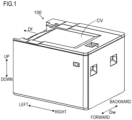
FIG. 1 is a perspective view of a feeding device according to an embodiment; -
FIG. 2 is a schematic view of an image forming system which includes the feeding device according to the embodiment; -
FIG. 3 is a perspective view in a state where an exterior cover in the feeding device according to the embodiment is omitted; -
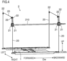
FIG. 4 is a perspective view of a raising/lowering mechanism for a set plate in the feeding device according to the embodiment; -
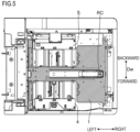
FIG. 5 is a plan view when a sheet storage region in the feeding device according to the embodiment is viewed from above; -
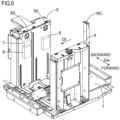
FIG. 6 is a perspective view of width-direction restriction cursors in the feeding device according to the embodiment and an area in the vicinity thereof; -
FIG. 7 is a perspective view of a dehumidification unit in the feeding device according to the embodiment; -
FIG. 8 is a block diagram of the feeding device according to the embodiment; -
FIG. 9 is a flowchart showing the flow of processing which is performed by a feeding control unit in the feeding device according to the embodiment; and -
FIG. 10 is a flowchart showing the flow of the processing which is performed by the feeding control unit in the feeding device according to the embodiment. - A
feeding device 100 according to an embodiment of the present disclosure and animage forming system 100S which includes thefeeding device 100 will be described below with reference toFIGS. 1 to 10 . - The
feeding device 100 has an external appearance as shown inFIG. 1 . As shown inFIG. 2 , thefeeding device 100 is coupled to animage forming apparatus 1000. Thefeeding device 100 is coupled to theimage forming apparatus 1000 to form theimage forming system 100S together with theimage forming apparatus 1000.FIG. 2 is a schematic view of theimage forming system 100S (that is, thefeeding device 100 coupled to the image forming apparatus 1000).FIG. 2 corresponds to a case where theimage forming system 100S is viewed from the front. - The
feeding device 100 is placed on a floor surface together with theimage forming apparatus 1000. A direction perpendicular to the floor surface (flat surface) on which thefeeding device 100 is placed is the up/down direction of thefeeding device 100. - The
feeding device 100 may be removable with respect to theimage forming apparatus 1000. Thefeeding device 100 is, for example, an optional device. Thefeeding device 100 when viewed from the front of theimage forming apparatus 1000 is arranged on the right side of theimage forming apparatus 1000. - The
feeding device 100 stores sheets S. The type of sheets S is not particularly limited. In thefeeding device 100, various types of sheets S such as plain paper and coated paper can be stored. Thefeeding device 100 feeds the sheet S to theimage forming apparatus 1000. - The
feeding device 100 feeds the sheet S from the right side of theimage forming apparatus 1000 toward theimage forming apparatus 1000. In the following description, a feeding direction in which the sheet S is fed by thefeeding device 100 is identified with a symbol Df. A direction parallel to the feeding direction Df is the left/right direction of thefeeding device 100. An upstream side in the feeding direction Df is the right side of thefeeding device 100, and a downstream side in the feeding direction Df is the left side of thefeeding device 100. - The feeding direction Df is one direction of horizontal directions orthogonal to the up/down direction. A direction which is horizontally orthogonal to the feeding direction Df corresponds to the width direction of the
feeding device 100. In the following description, the width direction of thefeeding device 100 is identified with a symbol Dw. The width direction Dw is also the forward/backward direction of thefeeding device 100. - The
image forming apparatus 1000 prints an image on the sheet S fed from thefeeding device 100. The printing system of theimage forming apparatus 1000 is an electrophotographic system. The printing system of theimage forming apparatus 1000 may be an inkjet system. - The
image forming apparatus 1000 coveys the sheet S fed from thefeeding device 100 along a conveyance path. Theimage forming apparatus 1000 prints the image on the sheet S being conveyed. InFIG. 2 , the conveyance path of the sheet S is represented by an arrow with dashed lines. - The
image forming apparatus 1000 includes aphotosensitive drum 1001 and atransfer roller 1002. Thephotosensitive drum 1001 carries a toner image on its circumferential surface. Thetransfer roller 1002 is pressed against thephotosensitive drum 1001 to form a transfer nip between itself and thephotosensitive drum 1001. Thetransfer roller 1002 is rotated together with thephotosensitive drum 1001. The sheet S being conveyed enters the transfer nip, and thus transfer processing is performed on the sheet S, with the result that the toner image is transferred to the sheet S. - The
image forming apparatus 1000 further includes a charging device, an exposure device and a development device though they are not shown in the figure. The charging device charges the circumferential surface of thephotosensitive drum 1001. The exposure device forms an electrostatic latent image on the circumferential surface of thephotosensitive drum 1001. The development device develops the electrostatic latent image on the circumferential surface of thephotosensitive drum 1001 into the toner image. - The
image forming apparatus 1000 includes a fixingroller pair 1003. The fixingroller pair 1003 includes a heating roller and a pressure roller. The heating roller incorporates a heater. The pressure roller is pressed against the heating roller to form a fixing nip between itself and the heating roller. The pressure roller is rotated together with the heating roller. The sheet S being conveyed enters the fixing nip, and thus fixing processing is performed on the sheet S. The toner image is fixed to the sheet S. The sheet S which has passed through the fixing nip is ejected to an ejection tray ET. - The
image forming apparatus 1000 includes afeeding roller 1004. Thefeeding roller 1004 feeds a sheet S to the conveyance path from a sheet cassette CA inside the main body of theimage forming apparatus 1000. In other words, theimage forming apparatus 1000 can also perform printing on sheets S set in the sheet cassette CA. - The
image forming apparatus 1000 also includes animage reading device 1005. Theimage reading device 1005 reads a document to generate image data of the document. Theimage forming apparatus 1000 can print an image based on the image data of the document on the sheet S (that is, can copy the document). - As shown in
FIG. 3 , thefeeding device 100 includes a front frame Ff and a rear frame Fr which are arranged opposite each other in the width direction Dw. The front frame Ff and the rear frame Fr are made of sheet metal. The front frame Ff is arranged on a front side, and the rear frame Fr is arranged on a back side. - The
feeding device 100 includes, as a sheet storage region, a region between the front frame Ff and the rear frame Fr in the width direction Dw. The sheet storage region is covered by an upper surface cover CV (seeFIGS. 1 and2 ) from above. In other words, thefeeding device 100 includes the upper surface cover CV. The upper surface cover CV corresponds to a "cover". - The upper surface cover CV is supported to be turnable with respect to the front frame Ff and the rear frame Fr. The upper surface cover CV is turnable around an axis line extending in the width direction Dw. The upper surface cover CV is turned with a left side end portion used as a support point such that a right side end portion swings vertically. In other words, the upper surface cover CV is opened and closed with respect to an upper opening in the sheet storage region. Furthermore, in other words, the upper surface cover CV is supported to be openable and closable.
- The
feeding device 100 includes aset plate 1. Theset plate 1 is made of sheet metal. Theset plate 1 is arranged between the front frame Ff and the rear frame Fr in the width direction Dw. On theset plate 1, the sheets S are set. In other words, a region on theset plate 1 is the sheet storage region. When a plurality of sheets S are provided, the sheets S are stacked on theset plate 1 in the up/down direction. - When a user performs an operation for setting the sheets S on the
set plate 1, the upper surface cover CV is opened and closed. In a state where the upper surface cover CV is closed, the right side end portion of the upper surface cover CV is turned upward, and thus the upper surface cover CV can be brought into an opened state. In a state where the upper surface cover CV is opened, the right side end portion of the upper surface cover CV is turned downward, and thus the upper surface cover CV can be brought into a closed state. - The upper surface cover CV is opened, and thus the sheet storage region on the
set plate 1 is exposed. In this way, the sheets S can be set on theset plate 1. The upper surface cover CV is closed, and thus the sheet storage region on theset plate 1 is covered. - The
feeding device 100 includes a raising/lowering mechanism 2. The configuration of the raising/lowering mechanism 2 is shown inFIG. 4 . The raising/lowering mechanism 2 moves theset plate 1 in the up/down direction. In other words, theset plate 1 is supported to be able to reciprocate in the up/down direction. The raising/lowering mechanism 2 raises theset plate 1, and thus the vertical position of the sheet S in the uppermost layer set on theset plate 1 is held to a predetermined position. - The raising/
lowering mechanism 2 includeswires 20 which are coupled to theset plate 1. The number ofwires 20 is four. Ends of thewires 20 are respectively coupled to the four corners of theset plate 1. A windingdrum 21 and arelay pulley 22 are assigned to each of thewires 20. Each of thewires 20 is wound around the correspondingrelay pulley 22. The other end of each of thewires 20 is coupled to the corresponding windingdrum 21. - Each of the winding
drums 21 is supported rotatably around the same axis line extending in the width direction Dw. In other words, the windingdrums 21 are attached to thesame rotation shaft 210, and are rotated together with therotation shaft 210. Therotation shaft 210 is coupled to an unillustrated winding motor, and the winding motor is driven to rotate therotation shaft 210. Each of the windingdrums 21 is rotated in forward and reverse directions to wind and unwind thewire 20. In other words, theset plate 1 is raised and lowered. - As shown in
FIGS. 2 and3 , thefeeding device 100 includes afeeding unit 3. Thefeeding unit 3 corresponds to a "feeding unit". Thefeeding unit 3 performs a feeding operation to feed the sheet S from theset plate 1. By thefeeding unit 3, the sheet S on theset plate 1 is fed from thefeeding device 100 to theimage forming apparatus 1000. Thefeeding unit 3 includes a pickup roller 31 and a conveyance roller pair 32. - The pickup roller 31 is rotatably supported. In a state where the sheet S is set on the
set plate 1, the pickup roller 31 is arranged in such a position that the pickup roller 31 can make contact with a downstream side end portion of the sheet S in the feeding direction Df from above. The pickup roller 31 makes contact with the sheet S set on theset plate 1 from above, and is rotated in this state to pull out the sheet S from theset plate 1. - The conveyance roller pair 32 is rotatably supported. The conveyance roller pair 32 is a pair of rollers which are pressed against each other. The conveyance roller pair 32 is arranged on the downstream side in the feeding direction Df with respect to the pickup roller 31. The conveyance roller pair 32 nips the sheet S pulled out from the
set plate 1 by the pickup roller 31, and is rotated. In this way, the conveyance roller pair 32 conveys the sheet S toward theimage forming apparatus 1000. The number of conveyance roller pairs 32 which are installed is not particularly limited, and can be changed according to, for example, the length of the conveyance path for the sheet S from the pickup roller 31 to theimage forming apparatus 1000. - The raising/
lowering mechanism 2 raises theset plate 1 to cause the sheet S in the uppermost layer on theset plate 1 to make contact with the pickup roller 31. When the sheet S is continuously fed from thefeeding device 100 to theimage forming apparatus 1000, the raising/lowering mechanism 2 raises theset plate 1 and stops the raising repeatedly. In this way, the contact of the sheet S in the uppermost layer on theset plate 1 with the pickup roller 31 is maintained. - As shown in
FIGS. 3 and5 , thefeeding device 100 includes width-direction restriction cursors direction restriction cursors direction restriction cursors direction restriction cursors - The width-
direction restriction cursors direction restriction cursor 4 is moved backward, the width-direction restriction cursor 4 is moved forward, and thus the distance between the width-direction restriction cursors direction restriction cursor 4 is moved forward, the width-direction restriction cursor 5 is moved backward, and thus the distance between the width-direction restriction cursors - The width-
direction restriction cursors set plate 1 in the width direction Dw. The width-direction restriction cursor 4 is moved from forward to backward to make contact with the end edge of the sheet S on theset plate 1 from forward. The width-direction restriction cursor 5 is moved from backward to forward to make contact with the end edge of the sheet S on theset plate 1 from backward. In this way, the width-direction restriction cursors set plate 1 in the width direction Dw. - The
feeding device 100 further includes a rear end restriction cursor RC. The rear end restriction cursor RC is supported to be able to reciprocate in the left/right direction. The user performs an operation, and thus the rear end restriction cursor RC is moved in the left/right direction. The rear end restriction cursor RC is moved from the upstream side to the downstream side in the feeding direction Df to make contact with the back end edge of the sheet S on theset plate 1. In this way, the rear end restriction cursor RC restricts a displacement of the sheet S on theset plate 1 to the upstream side in the feeding direction Df. - When the
set plate 1 is viewed from above, theset plate 1 includes an opening (the symbol of which is omitted) on the movement paths of the width-direction restriction cursors direction restriction cursors direction restriction cursors set plate 1. Even when the rear end restriction cursor RC is moved in the left/right direction, the rear end restriction cursor RC does not make contact with theset plate 1. In other words, when theset plate 1 is viewed from above, even if the sheet S is smaller than theset plate 1, the width-direction restriction cursors set plate 1, and the rear end restriction cursor RC can be brought into contact with the end edge of the sheet S without making contact with theset plate 1. InFIG. 5 , theset plate 1 is hatched. - As shown in
FIGS. 6 and7 , thefeeding device 100 includes a dehumidification unit D. The dehumidification unit D blows heated air to the sheet storage region on theset plate 1. In other words, the dehumidification unit D applies the hot air to the sheets S on theset plate 1. In this way, the dehumidification unit D performs dehumidification for the sheets S on theset plate 1. - The dehumidification unit D includes a
fan 6 and aheater 7. Thefan 6 is driven to blow the air to the sheets S on theset plate 1. Theheater 7 is arranged on the path of an airflow generated by thefan 6. Theheater 7 heats the air to be blown to the sheets S on theset plate 1. In this way, thefan 6 and theheater 7 are driven to apply the hot air to the sheets S on theset plate 1, and thus dehumidification is performed for the sheets S on theset plate 1. - The
fan 6 and theheater 7 are arranged in the width-direction restriction cursor 5 on the back side. In this configuration, the width-direction restriction cursor 5 corresponds to a " restriction cursor". - The
fan 6 and theheater 7 are arranged outward of the width-direction restriction cursor 5 in the width direction Dw. The "outward" of the width-direction restriction cursor 5 in the width direction Dw refers to the opposite side of the width-direction restriction cursor 5 (that is, the back side of the width-direction restriction cursor 5) to the side of the sheet storage region in the width direction Dw. Hence, in the width-direction restriction cursor 5, avent 50 which penetrates in the width direction Dw is formed. The hot air generated by thefan 6 and theheater 7 flows to the sheet storage region on theset plate 1 via thevent 50. - For example, the number of
fans 6 are two. The twofans 6 are arranged along the feeding direction Df. By contrast, the number ofheaters 7 is one. The oneheater 7 is assigned to thefan 6 of the twofans 6 located on the downstream side in the feeding direction Df. In other words, the onefan 6 heats the air to be blown by thefan 6 of the twofans 6 located on the downstream side in the feeding direction Df. - As shown in
FIG. 8 , thefeeding device 100 includes afeeding control unit 10. Thefeeding control unit 10 corresponds to a "control unit". Thefeeding control unit 10 includes aprocessing circuit 101 of a CPU, an ASIC and the like. Thefeeding control unit 10 includes astorage unit 102 of a ROM, a RAM, a HDD, an SSD and the like. - The
feeding control unit 10 is connected to a main control unit MC in theimage forming apparatus 1000. Thefeeding control unit 10 communicates with the main control unit MC. The main control unit MC receives, from the user, a job setting related to a job for feeding the sheet S with the feeding device 100 (hereinafter simply referred to as the job). For example, in theimage forming apparatus 1000, an operation panel (not shown) is provided, and the operation panel receives the job setting from the user. The main control unit MC recognizes the details of the job setting received by the operation panel. - The main control unit MC transmits, to the
feeding control unit 10, a control instruction based on the job setting indicated by the user. Thefeeding control unit 10 controls, based on the control instruction from the main control unit MC, processing for feeding the sheet S with the feeding device 100 (in other words, processing for feeding the sheet S from thefeeding device 100 to the image forming apparatus 1000). - For example, the main control unit MC transmits a feeding start command for the sheet S to the
feeding control unit 10. In other words, thefeeding control unit 10 receives the feeding start command from theimage forming apparatus 1000 which is the feeding destination of the sheet S. After thefeeding control unit 10 receives the feeding start command, thefeeding control unit 10 causes thefeeding unit 3 to start the feeding of the sheet S. In other words, thefeeding control unit 10 rotates the rotation member (the pickup roller 31 and the conveyance roller pair 32) of thefeeding unit 3. Thefeeding control unit 10 raises theset plate 1 to cause the sheet S in the uppermost layer on theset plate 1 to make contact with the pickup roller 31. In this way, the sheet S on theset plate 1 is fed to theimage forming apparatus 1000. - The
feeding control unit 10 controls dehumidification processing for the sheets S performed by the dehumidification unit D. In other words, thefeeding control unit 10 controls the driving of thefan 6. Thefeeding control unit 10 controls the driving of theheater 7. The dehumidification processing for the sheets S performed by the dehumidification unit D will be described in detail later. - The
feeding device 100 includes a temperature andhumidity sensor 11. The temperature andhumidity sensor 11 detects an internal temperature and an internal humidity of thefeeding device 100. The temperature andhumidity sensor 11 is connected to thefeeding control unit 10. Thefeeding control unit 10 detects the internal temperature and the internal humidity of thefeeding device 100 based on the output of the temperature andhumidity sensor 11. - The
feeding device 100 includes atemperature sensor 12. Thetemperature sensor 12 detects an external temperature of thefeeding device 100. Thetemperature sensor 12 is connected to thefeeding control unit 10. Thefeeding control unit 10 detects the external temperature of thefeeding device 100 based on the output of thetemperature sensor 12. Depending on circumstances, an outside air temperature detection sensor is provided in theimage forming apparatus 1000, and the outside air temperature detection sensor is connected to the main control unit MC. In this case, thetemperature sensor 12 may be omitted, and the main control unit MC may transmit information indicating an outside air temperature (that is, the external temperature of the feeding device 100) to thefeeding control unit 10. - The
feeding device 100 includes an opening/closing sensor 13. The opening/closing sensor 13 outputs a value corresponding to the opened/closed state of the upper surface cover CV. For example, when the upper surface cover CV is opened, the output value of the opening/closing sensor 13 is changed. The opening/closing sensor 13 is connected to thefeeding control unit 10. Thefeeding control unit 10 detects, based on the output of the opening/closing sensor 13, that the upper surface cover CV has been opened and that the upper surface cover CV has been closed. - The
feeding device 100 includes a heater temperature sensor 70 (for example, a thermistor). Theheater temperature sensor 70 detects the temperature of theheater 7. Theheater temperature sensor 70 is connected to thefeeding control unit 10. Thefeeding control unit 10 detects the temperature of theheater 7 based on the output of theheater temperature sensor 70. - Various types of sheets S are used in the job. For example, coated paper may be used. When the sheet S used in the job is the coated paper, depending on the internal temperature and the internal humidity of the
feeding device 100, the wetness of the sheets S is increased, and thus the sheets S stacked on theset plate 1 are difficult to separate from each other. In this way, when the sheet S on theset plate 1 is fed, simultaneous feeding in which a plurality of sheets S are fed together easily occurs. - In order to suppress the inconvenience described above, the dehumidification unit D is provided in the
feeding device 100. The dehumidification unit D performs dehumidification for the sheets S on theset plate 1. In this way, the simultaneous feeding of the sheets S is suppressed. - Here, when the dehumidification unit D is continuously driven regardless of the internal environment of the
feeding device 100, power consumption is increased. Moreover, when the dehumidification unit D is continuously driven regardless of the type of sheet S, power consumption is increased. Hence, thefeeding control unit 10 performs control along flows shown inFIGS. 9 and10 . - The flows of processing performed by the
feeding control unit 10 will be described below with reference to flowcharts shown inFIGS. 9 and10 . - When the
feeding control unit 10 receives a feeding start command from the feeding destination of the sheet S (that is, the image forming apparatus 1000), the flow shown inFIG. 9 is started. At the start of the flow shown inFIG. 9 , thefan 6 may be driven or thefan 6 may not be driven. On the other hand, theheater 7 is not driven. - In
step S 1, thefeeding control unit 10 determines whether the sheet S to be fed by thefeeding unit 3 is the coated paper. In other words, thefeeding control unit 10 determines whether the sheet S set on theset plate 1 is the coated paper. Furthermore, in other words, thefeeding control unit 10 determines whether the sheet S used in the job is the coated paper. When in step S1, thefeeding control unit 10 determines that the sheet S to be fed by thefeeding unit 3 is the coated paper, the processing transfers to step S2. - For example, the operation panel in the
image forming apparatus 1000 receives the type of sheet S on theset plate 1 from the user. When the user sets the sheet S on theset plate 1, the user inputs the type of sheet S set on theset plate 1 to the operation panel. The main control unit MC transmits, to thefeeding control unit 10, the type of sheet S input to the operation panel. In this way, thefeeding control unit 10 recognizes the type of sheet S set on theset plate 1. - In step S2, the
feeding control unit 10 recognizes the internal environment of thefeeding device 100 based on the output of the temperature andhumidity sensor 11. Then, thefeeding control unit 10 performs condition determination processing to determine whether the internal environment of thefeeding device 100 satisfies a predetermined condition. In other words, when the sheet S to be fed by thefeeding unit 3 is the coated paper, thefeeding control unit 10 performs the condition determination processing. - When the
feeding control unit 10 performs the condition determination processing, thefeeding control unit 10 determines an absolute humidity based on the output of the temperature andhumidity sensor 11. Thefeeding control unit 10 acquires the absolute humidity based on the output of the temperature andhumidity sensor 11 as the internal environment of thefeeding device 100. Then, thefeeding control unit 10 performs, as the condition determination processing, processing for determining that the predetermined condition is satisfied when the absolute humidity based on the output of the temperature andhumidity sensor 11 is higher than a threshold humidity. Thefeeding control unit 10 determines that the predetermined condition is not satisfied when the absolute humidity based on the output of the temperature andhumidity sensor 11 is equal to or less than the threshold humidity. In other words, the condition determination processing is processing for determining whether the simultaneous feeding of the sheets S easily occurs. A state where the simultaneous feeding of the sheets S easily occurs refers to a state where the absolute humidity based on the output of the temperature andhumidity sensor 11 is higher than the threshold humidity. - When in step S2, the
feeding control unit 10 determines that the predetermined condition is satisfied, the processing transfers to step S3. In other words, when thefeeding control unit 10 determines that the absolute humidity based on the output of the temperature andhumidity sensor 11 is higher than the threshold humidity, the processing transfers to step S3. Furthermore, in other words, when thefeeding control unit 10 determines that the simultaneous feeding of the sheets S easily occurs, the processing transfers to step S3. - In step S3, the
feeding control unit 10 starts the driving of the fan 6 (fan: on). Thefeeding control unit 10 drives thefan 6 at a predetermined reference rotation speed. Thefeeding control unit 10 performs PWM control to drive thefan 6. Here, thefeeding control unit 10 also starts the driving of the heater 7 (heater: on). When thefan 6 and theheater 7 are normally driven, the hot air is applied to the sheets S on theset plate 1, and thus dehumidification is performed. - When the
feeding control unit 10 determines that the predetermined condition is satisfied in the condition determination processing, thefeeding control unit 10 measures a first elapsed time that is a time which has elapsed since the start of the driving of theheater 7. In other words, when the processing transfers to step S3, thefeeding control unit 10 starts the measurement of the first elapsed time. - In step S4, the
feeding control unit 10 determines whether the temperature (HT) of theheater 7 is higher than a threshold temperature (Tt). When thefeeding control unit 10 determines that the temperature of theheater 7 is higher than the threshold temperature (HT > Tt), the processing transfers to step S5. The threshold temperature is a temperature (external temperature + 10°) which is 10 degrees higher than the external temperature of thefeeding device 100. In other words, the threshold temperature is changed depending on the external temperature of thefeeding device 100. - In step S5, the
feeding control unit 10 causes thefeeding unit 3 to start the feeding of the sheet S. In other words, when thefeeding control unit 10 determines that the predetermined condition is satisfied in the condition determination processing, thefeeding control unit 10 starts the driving of thefan 6 and theheater 7, and then causes thefeeding unit 3 to start the feeding of the sheet S. Thefeeding control unit 10 causes thefeeding unit 3 to feed the sheet S in a state where the upper surface cover CV is closed. - When in step S6, the feeding of the sheet S is completed, the
feeding control unit 10 stops the feeding operation of thefeeding unit 3. - When in step S1, the
feeding control unit 10 determines that the sheet S to be fed by thefeeding unit 3 is not the coated paper, the processing transfers to step S7. In step S7, thefeeding control unit 10 does not drive the fan 6 (fan: off). Thereafter, the processing transfers to step S5. - When in step S7, the
fan 6 is being driven, thefeeding control unit 10 stops the driving of thefan 6. When in step S7, the driving of thefan 6 is stopped, thefeeding control unit 10 maintains the stop of the driving of thefan 6. In any case, when the sheet S to be fed by thefeeding unit 3 is not the coated paper, thefeeding control unit 10 does not drive thefan 6 and theheater 7. - Even when in step S2, the
feeding control unit 10 determines that the predetermined condition is not satisfied, the processing transfers to step S7. In other words, when thefeeding control unit 10 determines that the predetermined condition is not satisfied in the condition determination processing, even if the sheet S to be fed by thefeeding unit 3 is the coated paper, thefeeding control unit 10 does not drive thefan 6 and theheater 7. - When in step S4, the
feeding control unit 10 determines that the temperature of theheater 7 is equal to or less than the threshold temperature (HT ≤ Tt), the processing transfers to step S8. - In step S8, the
feeding control unit 10 determines whether the first elapsed time has reached a first threshold time. When thefeeding control unit 10 determines that the first elapsed time has not reached the first threshold time, the processing transfers to step S4. When thefeeding control unit 10 determines that the first elapsed time has reached the first threshold time, the processing transfers to step S9. - In step S9, the
feeding control unit 10 performs error notification processing for notifying information indicating that an abnormality occurs in theheater 7. Specifically, when the temperature of theheater 7 reaches the threshold temperature before the first elapsed time reaches the first threshold time, thefeeding control unit 10 causes thefeeding unit 3 to start the feeding of the sheet S. On the other hand, even when the first elapsed time reaches the first threshold time, if the temperature of theheater 7 does not reach the threshold temperature, thefeeding control unit 10 performs the error notification processing. - The
feeding control unit 10 performs, as the error notification processing, processing for transmitting, to the main control unit MC, the information indicating that an abnormality occurs in theheater 7. When the main control unit MC receives the error notification from thefeeding control unit 10, the main control unit MC performs, for example, processing for displaying an error message on the operation panel. - When the feeding of the sheet S is completed, the processing transfers from step S6 to step S10 (see
FIG. 10 ). - In step S10, the
feeding control unit 10 determines whether thefan 6 is driven. That thefan 6 is driven at this point means that theheater 7 is also driven. On the other hand, that thefan 6 is not driven at this point means that theheater 7 is also not driven. - When in step S10, the
feeding control unit 10 determines that thefan 6 is not driven, the processing transfers to step S11. In step S11, thefeeding control unit 10 is brought into a standby state, and is kept on standby until the reception of a new feeding start command. Here, thefeeding control unit 10 does not drive thefan 6 and theheater 7. In other words, thefeeding control unit 10 does not drive theheater 7 after the completion of the feeding of the sheet S until the reception of the subsequent feeding start command. When thefeeding control unit 10 receives the subsequent feeding start command, the flow inFIG. 9 is started. - When in step S10, the
feeding control unit 10 determines that thefan 6 is driven, the processing transfers to step S12. In step S12, thefeeding control unit 10 stops the driving of the heater 7 (heater: off). Here, thefeeding control unit 10 stops the driving of theheater 7 regardless of whether the internal environment of thefeeding device 100 satisfies the predetermined condition (that is, regardless of whether the absolute humidity based on the temperature andhumidity sensor 11 is higher than the threshold humidity). However, thefeeding control unit 10 continues the driving of thefan 6. In other words, at this point, thefan 6 is driven in a state where the driving of theheater 7 is stopped. - The
feeding control unit 10 measures a second elapsed time that is a time which has elapsed since the stop of the driving of theheater 7. In other words, when the processing transfers to step S12, thefeeding control unit 10 starts the measurement of the second elapsed time. - In step S13, the
feeding control unit 10 determines whether the second elapsed time has reached a second threshold time. When thefeeding control unit 10 determines that the second elapsed time has reached the second threshold time, the processing transfers to step S14. In step S14, thefeeding control unit 10 stops the driving of the fan 6 (fan: off). Thereafter, the processing transfers to step S11. - When in step S13, the
feeding control unit 10 determines that the second elapsed time has not reached the second threshold time, the processing transfers to step S15. In step S15, thefeeding control unit 10 determines whether the upper surface cover CV has been opened. Thefeeding control unit 10 detects that the upper surface cover CV has been opened based on the output of the opening/closing sensor 13. - When in step S15, the
feeding control unit 10 determines that the upper surface cover CV has not been opened, the processing transfers to step S16. In step S16, thefeeding control unit 10 determines whether the subsequent feeding start command (that is, a new feeding start command) has been received from the main control unit MC. - When in step S16, the
feeding control unit 10 determines that the subsequent feeding start command has been received from the main control unit MC, the processing transfers to step S1 (seeFIG. 9 ). On the other hand, when thefeeding control unit 10 determines that the subsequent feeding start command has not been received from the main control unit MC, the processing transfers to step S13. In other words, when the second elapsed time reaches the second threshold time after the stop of the driving of theheater 7 before the reception of the subsequent feeding start command from the main control unit MC, thefeeding control unit 10 stops the driving of thefan 6. - When in step S15, the
feeding control unit 10 determines that the upper surface cover CV has been opened, the processing transfers to step S17. In step S17, while thefan 6 is being driven, thefeeding control unit 10 switches the rotation speed of thefan 6 to a low speed (fan: low speed). Thefeeding control unit 10 drives thefan 6 at a rotation speed lower than the reference rotation speed which is a rotation speed before the upper surface cover CV has been opened. Thereafter, the processing transfers to step S13. In other words, when the upper surface cover CV is opened after the stop of the driving of theheater 7, before the reception of the subsequent feeding start command from the main control unit MC and before the second elapsed time reaches the second threshold time, thefeeding control unit 10 drives thefan 6 at a rotation speed lower than a rotation speed before the upper surface cover CV has been opened. - In the present embodiment, when the
feeding control unit 10 determines that the predetermined condition is satisfied in the condition determination processing, thefeeding control unit 10 starts the driving of thefan 6 and theheater 7, and then causes thefeeding unit 3 to start the feeding of the sheet S. In other words, thefeeding control unit 10 causes thefeeding unit 3 to start the feeding of the sheet S while performing dehumidification for the sheets S to be fed by thefeeding unit 3. In this way, it is possible to suppress the simultaneous feeding of the sheets S. - Here, in the present embodiment, when the
feeding control unit 10 receives the feeding start command from the feeding destination of the sheet S, thefeeding control unit 10 performs the condition determination processing for determining whether thefan 6 and theheater 7 are driven. Furthermore, when the feeding of the sheet S is completed, thefeeding control unit 10 stops the driving of theheater 7 regardless of whether the internal environment of thefeeding device 100 satisfies the predetermined condition. In other words, thefeeding control unit 10 does not drive theheater 7 at least after the completion of the feeding of the sheet S until the reception of the subsequent feeding start command. In this way, an increase in power consumption caused by increasing the driving time of theheater 7 is suppressed. Consequently, it is possible to suppress the simultaneous feeding of the sheets S while suppressing an increase in power consumption in thefeeding device 100. - Although in the present embodiment, the driving of the
heater 7 is immediately stopped when the feeding of the sheet S is completed, the driving of thefan 6 is continued. In this way, it is possible to suppress an overshoot in theheater 7. - In the present embodiment, as described above, the
feeding control unit 10 determines that the predetermined condition is satisfied when the absolute humidity is higher than the threshold humidity. In this way, it is possible to easily perform dehumidification in a state where the simultaneous feeding of the sheets S easily occurs. - In the present embodiment, as described above, when the sheet S to be fed by the
feeding unit 3 is not the coated paper, thefeeding control unit 10 does not drive thefan 6 and theheater 7. Furthermore, when thefeeding control unit 10 determines that the predetermined condition is not satisfied in the condition determination processing, even if the sheet S to be fed by thefeeding unit 3 is the coated paper, thefeeding control unit 10 does not drive thefan 6 and theheater 7. In other words, only when the simultaneous feeding of the sheets S easily occurs, thefan 6 and theheater 7 are driven. In this way, it is possible to further suppress power consumption. - In the present embodiment, when the temperature of the
heater 7 reaches the threshold temperature before the first elapsed time reaches the first threshold time, thefeeding control unit 10 causes thefeeding unit 3 to start the feeding of the sheet S. On the other hand, even when the first elapsed time reaches the first threshold time, if the temperature of theheater 7 does not reach the threshold temperature, thefeeding control unit 10 performs the processing which notifies an error. Here, when an abnormality such as a broken wire occurs, the temperature of theheater 7 does not reach the threshold temperature. Hence, even when the first elapsed time reaches the first threshold time, if the temperature of theheater 7 does not reach the threshold temperature, the processing which notifies an error is preferably performed. - In the present embodiment, when as described above, the second elapsed time reaches the second threshold time after the stop of the driving of the
heater 7 before the reception of the subsequent feeding start command from the feeding destination of the sheet S, thefeeding control unit 10 stops the driving of thefan 6. In this way, it is possible to suppress unnecessary continuous driving of thefan 6. - In the present embodiment, when as described above, the
feeding control unit 10 detects that the upper surface cover CV has been opened based on the output of the opening/closing sensor 13 after the stop of the driving of theheater 7, before the reception of the subsequent feeding start command from the feeding destination of the sheet S and before the second elapsed time reaches the second threshold time, thefeeding control unit 10 drives thefan 6 at a rotation speed lower than a rotation speed before the upper surface cover CV has been opened. Here, that the upper surface cover CV has been opened indicates that the operation for setting the sheets S on theset plate 1 is performed. When the operation for setting the sheets S is performed, if an airflow is generated on theset plate 1, workability deteriorates. Hence, the rotation speed of thefan 6 is lowered. In this way, it is possible to suppress a decrease in the workability. - In the present embodiment, as described above, the
fan 6 and theheater 7 are arranged in the width-direction restriction cursor 5. In this way, it is possible to easily apply the hot air to the sheet S. - In the present embodiment, as described above, the
heater 7 is assigned to only thefan 6 located on the downstream side in the feeding direction Df. In this way, it is possible to further suppress power consumption. Here, the pickup roller 31 makes contact with the front end side (the downstream side in the feeding direction Df) of the sheets S. In this configuration, when dehumidification for the front end side of the sheets S is not sufficient, the simultaneous feeding of the sheets S easily occurs. Hence, the air which is blown by thefan 6 located on the downstream side in the feeding direction Df is preferably heated. - The embodiment disclosed herein should be considered to be illustrative in all respects and not restrictive. The scope of the present disclosure is indicated not by the description of the embodiment but by the scope of claims, and furthermore, meanings equivalent to the scope of claims and all changes in the scope are included therein.
Claims (10)
- A feeding device (100) comprising:a set plate (1) on which a sheet (S) is set;a feeding unit (3) that feeds the sheet (S) from the set plate (1);a fan (6) that blows air to the sheet (S) on the set plate (1);a heater (7) that heats the air to be blown to the sheet (S) on the set plate (1);a control unit (10) that controls the feeding of the sheet (S) performed by the feeding unit (3); anda temperature and humidity sensor (11) that detects an internal temperature and an internal humidity of the feeding device (100),wherein when the control unit (10) receives a feeding start command from a feeding destination of the sheet (S), if the sheet (S) to be fed by the feeding unit (3) is coated paper, the control unit (10)recognizes an internal environment of the feeding device (100) based on an output of the temperature and humidity sensor (11) andperforms condition determination processing to determine whether the internal environment satisfies a predetermined condition,when the control unit (10) determines that the predetermined condition is satisfied in the condition determination processing, the control unit (10)starts driving of the fan (6) and the heater (7) andthen causes the feeding unit (3) to start the feeding of the sheet (S) andwhen the feeding of the sheet (S) in a state where the fan (6) and the heater (7) are driven is completed, the control unit (10)
stops the driving of the heater (7) and continues the driving of the fan (6) regardless of whether the internal environment satisfies the predetermined condition. - The feeding device (100) according to claim 1,wherein the internal environment is an absolute humidity, andwhen the absolute humidity is higher than a threshold humidity, the control unit (10) determines that the predetermined condition is satisfied.
- The feeding device (100) according to claim 1 or 2,
wherein when the sheet (S) to be fed by the feeding unit (3) is not the coated paper, the control unit (10) does not drive the fan (6) and the heater (7). - The feeding device (100) according to any one of claims 1 to 3,
wherein when the control unit (10) determines that the predetermined condition is not satisfied in the condition determination processing, even if the sheet (S) to be fed by the feeding unit (3) is the coated paper, the control unit (10) does not drive the fan (6) and the heater (7). - The feeding device (100) according to any one of claims 1 to 4,wherein when the control unit (10) determines that the predetermined condition is satisfied in the condition determination processing, the control unit (10) measures a first elapsed time that is a time which has elapsed since a start of the driving of the heater (7),when a temperature of the heater (7) reaches a threshold temperature before the first elapsed time reaches a first threshold time, the control unit (10) causes the feeding unit (3) to start the feeding of the sheet (S) andeven when the first elapsed time reaches the first threshold time, if the temperature of the heater (7) does not reach the threshold temperature, the control unit (10) performs processing that notifies an error.
- The feeding device (100) according to any one of claims 1 to 5,wherein the control unit (10) measures a second elapsed time that is a time which has elapsed since a stop of the driving of the heater (7), andwhen the second elapsed time reaches a second threshold time after the stop of the driving of the heater (7) before reception of a feeding start command subsequent to the feeding start command, the control unit (10) stops the driving of the fan (6).
- The feeding device (100) according to claim 6, further comprising:a cover (CV) that is supported to be openable and closable; andan opening/closing sensor (13) that detects opening and closing of the cover (CV),wherein the cover (CV) is opened to cause a region on the set plate (1) to be exposed such that the sheet (S) can be set, and the cover (CV) is closed to cover the region on the set plate (1),the control unit (10) causes the feeding unit (3) to feed the sheet (S) in a state where the cover (CV) is closed andwhen the control unit (10) detects that the cover (CV) has been opened based on an output of the opening/closing sensor (13) after the stop of the driving of the heater (7), before the reception of the feeding start command subsequent to the feeding start command and before the second elapsed time reaches the second threshold time, the control unit (10) drives the fan (6) at a rotation speed lower than a rotation speed before the cover (CV) has been opened.
- The feeding device (100) according to any one of claims 1 to 7, further comprising:a restriction cursor (5) that makes contact with an end edge of the sheet (S) on the set plate (1) in a width direction orthogonal to a feeding direction to restrict a displacement of the sheet (S) in the width direction,wherein the fan (6) and the heater (7) are arranged in the restriction cursor (5).
- The feeding device (100) according to claim 8,wherein two fans (6) each being the fan (6) and one heater (7) being the heater (7) are provided,the two fans (6) are arranged along the feeding direction andthe one heater (7) heats the air to be blown by the fan (6) of the two fans (6) that is arranged on a downstream side in the feeding direction.
- An image forming system (100S) comprising:the feeding device (100) according to any one of claims 1 to 9; andan image forming apparatus (1000) coupled to the feeding device (100),wherein the feeding device (100) feeds the sheet (S) to the image forming apparatus (1000), andthe image forming apparatus (1000) performs printing on the sheet (S) fed from the feeding device (100).
Applications Claiming Priority (1)
| Application Number | Priority Date | Filing Date | Title |
|---|---|---|---|
| JP2023214784A JP2025098563A (en) | 2023-12-20 | 2023-12-20 | Feed device and image formation system with the same |
Publications (1)
| Publication Number | Publication Date |
|---|---|
| EP4575655A1 true EP4575655A1 (en) | 2025-06-25 |
Family
ID=93923994
Family Applications (1)
| Application Number | Title | Priority Date | Filing Date |
|---|---|---|---|
| EP24219759.8A Pending EP4575655A1 (en) | 2023-12-20 | 2024-12-13 | Feeding device and image forming system including same |
Country Status (3)
| Country | Link |
|---|---|
| US (1) | US12606395B2 (en) |
| EP (1) | EP4575655A1 (en) |
| JP (1) | JP2025098563A (en) |
Citations (3)
| Publication number | Priority date | Publication date | Assignee | Title |
|---|---|---|---|---|
| JP2005096994A (en) * | 2003-08-26 | 2005-04-14 | Canon Inc | Sheet feeding apparatus and image forming apparatus provided with the same |
| US20100001454A1 (en) * | 2008-07-01 | 2010-01-07 | Kyocera Mita Corporation | Sheet feeding device and image forming apparatus including sheet feeding device |
| JP2011057397A (en) * | 2009-09-11 | 2011-03-24 | Canon Inc | Image forming system |
Family Cites Families (3)
| Publication number | Priority date | Publication date | Assignee | Title |
|---|---|---|---|---|
| US20050067757A1 (en) | 2003-08-26 | 2005-03-31 | Takeshi Suga | Sheet feeding apparatus and image forming apparatus having the same |
| JP2005096946A (en) | 2003-09-25 | 2005-04-14 | Canon Inc | Image forming apparatus |
| JP2020020854A (en) * | 2018-07-30 | 2020-02-06 | キヤノン株式会社 | Image forming device |
-
2023
- 2023-12-20 JP JP2023214784A patent/JP2025098563A/en active Pending
-
2024
- 2024-12-12 US US18/978,394 patent/US12606395B2/en active Active
- 2024-12-13 EP EP24219759.8A patent/EP4575655A1/en active Pending
Patent Citations (3)
| Publication number | Priority date | Publication date | Assignee | Title |
|---|---|---|---|---|
| JP2005096994A (en) * | 2003-08-26 | 2005-04-14 | Canon Inc | Sheet feeding apparatus and image forming apparatus provided with the same |
| US20100001454A1 (en) * | 2008-07-01 | 2010-01-07 | Kyocera Mita Corporation | Sheet feeding device and image forming apparatus including sheet feeding device |
| JP2011057397A (en) * | 2009-09-11 | 2011-03-24 | Canon Inc | Image forming system |
Also Published As
| Publication number | Publication date |
|---|---|
| US12606395B2 (en) | 2026-04-21 |
| JP2025098563A (en) | 2025-07-02 |
| US20250206559A1 (en) | 2025-06-26 |
Similar Documents
| Publication | Publication Date | Title |
|---|---|---|
| JP5072439B2 (en) | Image forming apparatus | |
| JP5720646B2 (en) | Paper feeding device and image forming apparatus | |
| JP5216698B2 (en) | Paper feeding device and image forming apparatus having the same | |
| JP2010064805A (en) | Paper feeder and image forming device having the same | |
| US9201374B2 (en) | Image forming apparatus | |
| US12606395B2 (en) | Feeding device and image forming system including same | |
| JP7588473B2 (en) | Sheet feeding device and image forming system | |
| JPH11352840A (en) | Image forming device | |
| JP5803971B2 (en) | Paper feeding device, image forming apparatus, and image forming system | |
| JP5058927B2 (en) | Paper feeding device and image forming apparatus having the same | |
| JP5236381B2 (en) | Image forming apparatus | |
| JP5368026B2 (en) | Paper feeding device and image forming apparatus having the same | |
| JP6617631B2 (en) | Image forming apparatus | |
| JP2016060606A (en) | Image forming apparatus | |
| JP5548806B2 (en) | Paper feeding device and image forming apparatus having the same | |
| JP7078408B2 (en) | Sheet feeder and image forming system | |
| JP7316160B2 (en) | Recording device and its control method | |
| JP5330584B2 (en) | Image forming apparatus | |
| JP5651796B2 (en) | Paper feeding device and image forming apparatus having the same | |
| JP7409805B2 (en) | Sheet conveyance device and image forming system | |
| US10338523B2 (en) | Image forming apparatus capable of preventing fine particles from flowing out of apparatus and image forming method | |
| JP2015011263A (en) | Image forming apparatus | |
| JPH08211756A (en) | Second-stage transfer corrugator | |
| JP6477599B2 (en) | Image forming apparatus and conveyance control method | |
| JP5066503B2 (en) | Duplex printing unit and image forming apparatus having the same |
Legal Events
| Date | Code | Title | Description |
|---|---|---|---|
| PUAI | Public reference made under article 153(3) epc to a published international application that has entered the european phase |
Free format text: ORIGINAL CODE: 0009012 |
|
| STAA | Information on the status of an ep patent application or granted ep patent |
Free format text: STATUS: THE APPLICATION HAS BEEN PUBLISHED |
|
| AK | Designated contracting states |
Kind code of ref document: A1 Designated state(s): AL AT BE BG CH CY CZ DE DK EE ES FI FR GB GR HR HU IE IS IT LI LT LU LV MC ME MK MT NL NO PL PT RO RS SE SI SK SM TR |
|
| STAA | Information on the status of an ep patent application or granted ep patent |
Free format text: STATUS: REQUEST FOR EXAMINATION WAS MADE |
|
| 17P | Request for examination filed |
Effective date: 20250908 |