EP4575650A1 - Image forming apparatus - Google Patents
Image forming apparatus Download PDFInfo
- Publication number
- EP4575650A1 EP4575650A1 EP24221563.0A EP24221563A EP4575650A1 EP 4575650 A1 EP4575650 A1 EP 4575650A1 EP 24221563 A EP24221563 A EP 24221563A EP 4575650 A1 EP4575650 A1 EP 4575650A1
- Authority
- EP
- European Patent Office
- Prior art keywords
- image forming
- duct
- axis direction
- forming apparatus
- air flow
- Prior art date
- Legal status (The legal status is an assumption and is not a legal conclusion. Google has not performed a legal analysis and makes no representation as to the accuracy of the status listed.)
- Pending
Links
Images


Classifications
-
- G—PHYSICS
- G03—PHOTOGRAPHY; CINEMATOGRAPHY; ANALOGOUS TECHNIQUES USING WAVES OTHER THAN OPTICAL WAVES; ELECTROGRAPHY; HOLOGRAPHY
- G03G—ELECTROGRAPHY; ELECTROPHOTOGRAPHY; MAGNETOGRAPHY
- G03G21/00—Arrangements not provided for by groups G03G13/00 - G03G19/00, e.g. cleaning, elimination of residual charge
- G03G21/20—Humidity or temperature control also ozone evacuation; Internal apparatus environment control
- G03G21/206—Conducting air through the machine, e.g. for cooling, filtering, removing gases like ozone
-
- G—PHYSICS
- G03—PHOTOGRAPHY; CINEMATOGRAPHY; ANALOGOUS TECHNIQUES USING WAVES OTHER THAN OPTICAL WAVES; ELECTROGRAPHY; HOLOGRAPHY
- G03G—ELECTROGRAPHY; ELECTROPHOTOGRAPHY; MAGNETOGRAPHY
- G03G15/00—Apparatus for electrographic processes using a charge pattern
- G03G15/01—Apparatus for electrographic processes using a charge pattern for producing multicoloured copies
-
- G—PHYSICS
- G03—PHOTOGRAPHY; CINEMATOGRAPHY; ANALOGOUS TECHNIQUES USING WAVES OTHER THAN OPTICAL WAVES; ELECTROGRAPHY; HOLOGRAPHY
- G03G—ELECTROGRAPHY; ELECTROPHOTOGRAPHY; MAGNETOGRAPHY
- G03G15/00—Apparatus for electrographic processes using a charge pattern
- G03G15/01—Apparatus for electrographic processes using a charge pattern for producing multicoloured copies
- G03G15/0105—Details of unit
- G03G15/0121—Details of unit for developing
-
- G—PHYSICS
- G03—PHOTOGRAPHY; CINEMATOGRAPHY; ANALOGOUS TECHNIQUES USING WAVES OTHER THAN OPTICAL WAVES; ELECTROGRAPHY; HOLOGRAPHY
- G03G—ELECTROGRAPHY; ELECTROPHOTOGRAPHY; MAGNETOGRAPHY
- G03G15/00—Apparatus for electrographic processes using a charge pattern
- G03G15/06—Apparatus for electrographic processes using a charge pattern for developing
- G03G15/08—Apparatus for electrographic processes using a charge pattern for developing using a solid developer, e.g. powder developer
- G03G15/0822—Arrangements for preparing, mixing, supplying or dispensing developer
- G03G15/0865—Arrangements for supplying new developer
-
- G—PHYSICS
- G03—PHOTOGRAPHY; CINEMATOGRAPHY; ANALOGOUS TECHNIQUES USING WAVES OTHER THAN OPTICAL WAVES; ELECTROGRAPHY; HOLOGRAPHY
- G03G—ELECTROGRAPHY; ELECTROPHOTOGRAPHY; MAGNETOGRAPHY
- G03G15/00—Apparatus for electrographic processes using a charge pattern
- G03G15/14—Apparatus for electrographic processes using a charge pattern for transferring a pattern to a second base
- G03G15/16—Apparatus for electrographic processes using a charge pattern for transferring a pattern to a second base of a toner pattern, e.g. a powder pattern, e.g. magnetic transfer
-
- G—PHYSICS
- G03—PHOTOGRAPHY; CINEMATOGRAPHY; ANALOGOUS TECHNIQUES USING WAVES OTHER THAN OPTICAL WAVES; ELECTROGRAPHY; HOLOGRAPHY
- G03G—ELECTROGRAPHY; ELECTROPHOTOGRAPHY; MAGNETOGRAPHY
- G03G21/00—Arrangements not provided for by groups G03G13/00 - G03G19/00, e.g. cleaning, elimination of residual charge
- G03G21/16—Mechanical means for facilitating the maintenance of the apparatus, e.g. modular arrangements
- G03G21/1604—Arrangement or disposition of the entire apparatus
- G03G21/1609—Arrangement or disposition of the entire apparatus for space saving, e.g. structural arrangements
-
- H—ELECTRICITY
- H04—ELECTRIC COMMUNICATION TECHNIQUE
- H04N—PICTORIAL COMMUNICATION, e.g. TELEVISION
- H04N1/00—Scanning, transmission or reproduction of documents or the like, e.g. facsimile transmission; Details thereof
- H04N1/00519—Constructional details not otherwise provided for, e.g. housings, covers
- H04N1/00525—Providing a more compact apparatus, e.g. sheet discharge tray in cover
- H04N1/00527—Discharge tray at least partially sandwiched between image generating and reproducing components
-
- G—PHYSICS
- G03—PHOTOGRAPHY; CINEMATOGRAPHY; ANALOGOUS TECHNIQUES USING WAVES OTHER THAN OPTICAL WAVES; ELECTROGRAPHY; HOLOGRAPHY
- G03G—ELECTROGRAPHY; ELECTROPHOTOGRAPHY; MAGNETOGRAPHY
- G03G15/00—Apparatus for electrographic processes using a charge pattern
- G03G15/65—Apparatus which relate to the handling of copy material
- G03G15/6552—Means for discharging uncollated sheet copy material, e.g. discharging rollers, exit trays
-
- G—PHYSICS
- G03—PHOTOGRAPHY; CINEMATOGRAPHY; ANALOGOUS TECHNIQUES USING WAVES OTHER THAN OPTICAL WAVES; ELECTROGRAPHY; HOLOGRAPHY
- G03G—ELECTROGRAPHY; ELECTROPHOTOGRAPHY; MAGNETOGRAPHY
- G03G15/00—Apparatus for electrographic processes using a charge pattern
- G03G15/65—Apparatus which relate to the handling of copy material
- G03G15/6555—Handling of sheet copy material taking place in a specific part of the copy material feeding path
- G03G15/6573—Feeding path after the fixing point and up to the discharge tray or the finisher, e.g. special treatment of copy material to compensate for effects from the fixing
-
- G—PHYSICS
- G03—PHOTOGRAPHY; CINEMATOGRAPHY; ANALOGOUS TECHNIQUES USING WAVES OTHER THAN OPTICAL WAVES; ELECTROGRAPHY; HOLOGRAPHY
- G03G—ELECTROGRAPHY; ELECTROPHOTOGRAPHY; MAGNETOGRAPHY
- G03G2215/00—Apparatus for electrophotographic processes
- G03G2215/00004—Handling of entire apparatus
- G03G2215/00008—Upright positioning for maintenance or storage
-
- G—PHYSICS
- G03—PHOTOGRAPHY; CINEMATOGRAPHY; ANALOGOUS TECHNIQUES USING WAVES OTHER THAN OPTICAL WAVES; ELECTROGRAPHY; HOLOGRAPHY
- G03G—ELECTROGRAPHY; ELECTROPHOTOGRAPHY; MAGNETOGRAPHY
- G03G2215/00—Apparatus for electrophotographic processes
- G03G2215/00004—Handling of entire apparatus
- G03G2215/00012—Upright positioning as well as horizontal positioning for image forming
-
- G—PHYSICS
- G03—PHOTOGRAPHY; CINEMATOGRAPHY; ANALOGOUS TECHNIQUES USING WAVES OTHER THAN OPTICAL WAVES; ELECTROGRAPHY; HOLOGRAPHY
- G03G—ELECTROGRAPHY; ELECTROPHOTOGRAPHY; MAGNETOGRAPHY
- G03G2215/00—Apparatus for electrophotographic processes
- G03G2215/00362—Apparatus for electrophotographic processes relating to the copy medium handling
- G03G2215/00367—The feeding path segment where particular handling of the copy medium occurs, segments being adjacent and non-overlapping. Each segment is identified by the most downstream point in the segment, so that for instance the segment labelled "Fixing device" is referring to the path between the "Transfer device" and the "Fixing device"
- G03G2215/00417—Post-fixing device
- G03G2215/00421—Discharging tray, e.g. devices stabilising the quality of the copy medium, postfixing-treatment, inverting, sorting
-
- G—PHYSICS
- G03—PHOTOGRAPHY; CINEMATOGRAPHY; ANALOGOUS TECHNIQUES USING WAVES OTHER THAN OPTICAL WAVES; ELECTROGRAPHY; HOLOGRAPHY
- G03G—ELECTROGRAPHY; ELECTROPHOTOGRAPHY; MAGNETOGRAPHY
- G03G2215/00—Apparatus for electrophotographic processes
- G03G2215/00362—Apparatus for electrophotographic processes relating to the copy medium handling
- G03G2215/00367—The feeding path segment where particular handling of the copy medium occurs, segments being adjacent and non-overlapping. Each segment is identified by the most downstream point in the segment, so that for instance the segment labelled "Fixing device" is referring to the path between the "Transfer device" and the "Fixing device"
- G03G2215/00417—Post-fixing device
- G03G2215/00426—Post-treatment device adding qualities to the copy medium product
-
- G—PHYSICS
- G03—PHOTOGRAPHY; CINEMATOGRAPHY; ANALOGOUS TECHNIQUES USING WAVES OTHER THAN OPTICAL WAVES; ELECTROGRAPHY; HOLOGRAPHY
- G03G—ELECTROGRAPHY; ELECTROPHOTOGRAPHY; MAGNETOGRAPHY
- G03G2221/00—Processes not provided for by group G03G2215/00, e.g. cleaning or residual charge elimination
- G03G2221/16—Mechanical means for facilitating the maintenance of the apparatus, e.g. modular arrangements and complete machine concepts
- G03G2221/1645—Mechanical means for facilitating the maintenance of the apparatus, e.g. modular arrangements and complete machine concepts for conducting air through the machine, e.g. cooling
Definitions
- the present invention relates to an image forming apparatus that forms images on sheets.
- Japanese Patent Application Publication No. 2015-141227 proposes an image forming apparatus that includes an image forming apparatus body and a document reading apparatus disposed above the image forming apparatus body.
- an image forming apparatus water vapor produced in the image forming apparatus body is discharged from a sheet discharge port, and water vapor is produced from a sheet discharged from the sheet discharge port.
- a duct space is formed by a top surface of the image forming apparatus body and a bottom surface of the document reading apparatus. The duct space communicates with a space formed between the image forming apparatus body and the document reading apparatus, and with the back surface of the image forming apparatus.
- part of the water vapor that fills the above-described space is discharged to the back surface of the image forming apparatus through the duct space, due to the natural convection, so that the occurrence of dew condensation is suppressed in the bottom surface of the document reading apparatus.
- Japanese Patent Application Publication No. 2017-3713 proposes an image forming apparatus that prevents sheets from sticking to each other due to remelting of toner on the sheets.
- an air blowing port is disposed above a nip of a discharging roller pair that discharges sheets, and the air is blown on the sheets from the air blowing port for suppressing the sheets from sticking to each other.
- the image forming apparatus described in Japanese Patent Application Publication No. 2015-141227 since the duct space is formed between the image forming apparatus body and the document reading apparatus, the image forming apparatus is upsized in the height direction, by the size of the duct space. Also, in the image forming apparatus described in Japanese Patent Application Publication No. 2017-3713 , since it is necessary to dispose a duct for sending the air to the air blowing port disposed above the nip of the discharging roller pair, the image forming apparatus is upsized in the height direction, by the size of the duct.
- the image forming apparatus is upsized. Thus, it has not been possible that suppressing the image defect and the occurrence of dew condensation and downsizing the image forming apparatus are both achieved.
- the present invention in its first aspect provides an image forming apparatus as specified in claims 1 to 12.
- the X-axis direction, the Y-axis direction, and the Z-axis direction are orthogonal to each other.
- the X-axis direction that serves as a first direction is a direction along a below-described sheet discharging direction DD.
- the X-axis direction is parallel to a horizontal direction and is orthogonal to the rotation-axis direction of a below-described photosensitive drum 42.
- the Y-axis direction is the rotation-axis direction of the photosensitive drum 42 that serves as an image bearing member.
- the Z-axis direction that serves as a second direction is the height direction of the image forming apparatus 100, and is parallel to the vertical direction and the gravity direction.
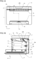
- FIG. 1A is a front view illustrating the image forming apparatus 100.
- FIG. 1B is a cross-sectional view illustrating a cross section taken along a line A-A of FIG. 1A .
- the image forming apparatus 100 of the present embodiment is an electrophotographic monochrome laser-beam printer, and is a multifunction printer having a document reading function.
- examples of the image forming apparatus include a printer, a copying machine, a facsimile, and a multifunction printer; and the image forming apparatus forms images on sheets, used as a recording medium, in accordance with image information sent from an external PC or read from a document.
- an apparatus such as an option feeder or a sheet processing apparatus
- the whole system in which the apparatus is attached to the body is also a type of the image forming apparatus.
- the document or the sheet may be a paper sheet, such as a sheet for any purpose or an envelope, a plastic film such as an overhead projector (OHT) sheet, or a cloth sheet.
- the image forming apparatus 100 includes a reading unit 2 that reads the image data of a document, and an image forming unit 1 disposed below the reading unit 2.
- the reading unit 2 is pivotably supported around an opening-and-closing shaft disposed in an upper and back portion of the image forming unit 1 so as to be opened and closed with respect to the image forming unit 1.
- the reading unit 2 includes a document platen glass 2a on which a document is placed, and a reading portion 2b which reads the image information of a document placed on the document platen glass 2a, by optically scanning the document.
- the reading unit 2 may include an auto document feeder (ADF) that feeds a document placed on a document tray.
- ADF auto document feeder
- the image information is converted into an electrical signal by the reading unit 2, and is sent to a control portion (not illustrated) disposed in the image forming unit 1.
- the image forming unit 1 includes a feeding portion 5 that feeds a sheet P, an image forming portion 40 that forms an image on the sheet P, a fixing portion 7 that fixes the image to the sheet P, a discharging roller pair 8 that serves as a discharging portion, and the like.
- a discharging space 10 is formed between the reading unit 2 and the image forming unit 1, and the sheet P is discharged to the discharging space 10.
- a discharging tray 9 is disposed, and the sheet P discharged to the discharging space 10 is stacked on the discharging tray 9.
- the image forming portion 40 includes a laser scanner 41, the photosensitive drum 42, a charging roller (not illustrated), a developing roller (not illustrated), and a transfer roller 43.
- the charging roller and the developing roller are disposed around the photosensitive drum 42.
- the photosensitive drum 42 is irradiated with a laser beam emitted from the laser scanner 41 and corresponding to the image data.
- the surface of the photosensitive drum 42 is uniformly charged in advance by the charging roller so as to have a predetermined polarity and potential, an electrostatic latent image is formed on the surface when the surface is irradiated with the laser beam from the laser scanner 41.
- the electrostatic latent image formed on the photosensitive drum 42 is developed by the developing roller, and a toner image is formed on the photosensitive drum 42.
- a sheet P placed on a sheet tray 5a of the feeding portion 5 is fed to a conveyance path CP by a pickup roller 5b.
- the toner image formed on the photosensitive drum 42 is transferred, at the transfer nip 6, onto the sheet P fed by the pickup roller 5b, by the transfer bias applied to the transfer roller 43.
- the sheet P onto which the toner image has been transferred is then applied with predetermined heat and pressure by the fixing portion 7, so that the toner is melted and solidifies (fixed).
- the sheet P having passed through the fixing portion 7 is discharged to the discharging tray 9 by the discharging roller pair 8.
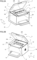
- FIG. 2A is a perspective view illustrating the image forming apparatus 100.
- FIG. 2B is another perspective view illustrating the image forming apparatus 100. Note that in FIGS. 2A and 2B , the reading unit 2 is opened with respect to the image forming unit 1.
- the discharging space 10 to which the sheet P is discharged in the sheet discharging direction DD, is formed between the image forming unit 1 and the reading unit 2.
- the discharging space 10 is covered by the image forming unit 1 and the reading unit 2, except for an opening portion 3 of the image forming apparatus 100 on the front side.
- the discharging space 10 is formed by the discharging tray 9, on which the discharged sheet P is stacked, a rising surface 51, a first side-surface 23a, a second side-surface 23b, and a bottom surface 11 of the reading unit 2.
- the rising surface 51 extends in the Y-axis direction and the Z-axis direction.
- a sheet discharge port 51a through which the sheet P discharged by the discharging roller pair 8 passes, is formed.
- the discharging tray 9 that serves as a stacking surface extends upward as the discharging tray 9 extends downstream in the sheet discharging direction DD.
- the first side-surface 23a is formed on a first side (i.e., the right side) of the discharging tray 9 in the Y-axis direction, and extends in the X-axis direction and the Z-axis direction.
- the second side-surface 23b is formed on a second side (i.e., the left side) of the discharging tray 9 in the Y-axis direction, and extends in the X-axis direction and the Z-axis direction.
- a side-surface opening 25 that serves as a second discharge port is formed in the first side-surface 23a.
- the image forming unit 1 includes a side cover 24 that forms an exterior surface. As illustrated in FIG. 1B , the side cover 24 includes a back surface 24a that serves as an outside surface of the image forming unit 1 on the upstream side in the sheet discharging direction DD. In the right side-surface of the side cover 24, an intake louver 28 having a plurality of holes is formed.
- the image forming unit 1 also includes a top cover 52 that forms a top surface of the image forming unit 1. In the top cover 52, a concave portion 52a is formed, and the concave portion 52a is concaved so as to be separated from the bottom surface 11 of the reading unit 2.
- the concave portion 52a and the bottom surface 11 of the reading unit 2 form a first duct 22 that extends in the X-axis direction.
- the first duct 22 communicates the discharging space 10 with the back surface 24a of the image forming unit 1.
- a width L1 of the first duct 22 is smaller than a width L2 of the discharging tray 9.
- the first duct 22 is disposed at a position closer to the second side-surface 23b than to the first side-surface 23a in the Y-axis direction. More specifically, the first duct 22 is formed such that one end surface of the first duct 22 in the Y-axis direction is flush with the second side-surface 23b.
- FIG. 3A is a perspective view illustrating the image forming unit 1 in a state where the side cover 24 is removed.
- FIG. 3B is another perspective view illustrating the image forming unit 1 in the state where the side cover 24 is removed.
- FIG. 4A is a perspective view illustrating a dew-condensation adhesion range of an image forming apparatus 200 of a comparative example.
- FIG. 4B is a perspective view illustrating a flow of air flow and a dew-condensation adhesion range of the image forming apparatus 100 of the present embodiment.
- the image forming unit 1 includes a fan 13, an intermediate duct 14, and a second duct 15.
- a direction from the first side-surface 23a (see FIG. 2A ) toward the second side-surface 23b (see FIG. 2B ) in the Y-axis direction is defined as a -Y direction that serves as a first axis direction.
- the fan 13 and the intermediate duct 14 are disposed upstream of the discharging space 10 in the -Y direction.
- the fan 13 and the intermediate duct 14 are fixed to a side plate 53 that is a part of a frame of the image forming unit 1.
- the fan 13 sends air flow toward the intermediate duct 14.
- the intermediate duct 14 that serves as a third duct extends in the Z-axis direction.
- the fan 13 is a centrifugal fan in the present embodiment, the present disclosure is not limited to this.
- the fan 13 may be an axial-flow fan that sends air flow along the rotation-axis direction of the blade portion.
- a branch portion 17 is disposed for branching the air flow generated by the fan 13.
- the air flow that has flowed in the intermediate duct 14 is divided, by the branch portion 17, into the air flow that flows toward the second duct 15 in a direction indicated by an arrow B, and into the air flow that flows in a direction indicated by an arrow C, toward the side-surface opening 25 formed in the first side-surface 23a, through a side-surface discharge port 19 formed in an upper end portion of the intermediate duct 14. That is, the intermediate duct 14 guides part of the air flow generated by the fan 13, to the second duct 15.
- the second duct 15 extends in the Y-axis direction, and the air flow for cooling the sheet to be discharged by the discharging roller pair 8 flows in the second duct 15. More specifically, the air flow that will flow from the upper end portion of the intermediate duct 14 toward the above-described direction indicated by the arrow B flows into the second duct 15, and the air flow flows in the second duct 15 toward the -Y direction. In other words, the fan 13 generates the air flow that flows in the second duct 15 toward the -Y direction.
- the direction of the air flow that flows in the -Y direction in the second duct 15 is changed to a direction along the sheet discharging direction DD, by a plurality of rectifying plates 16 disposed in the second duct 15.
- a cooling discharge port 18 that communicates the second duct 15 with the discharging space 10 is formed.
- the cooling discharge port 18 that serves as a first discharge port may be formed integrally with, or separated from the sheet discharge port 51a (see FIG. 2A ).
- the air flow whose direction has been changed to the direction along the sheet discharging direction DD by the plurality of rectifying plates 16 passes through the cooling discharge port 18, and is discharged toward the discharging space 10 in a direction indicated by an arrow D.
- the air flow discharged, in this manner, toward the discharging space 10 in the direction indicated by the arrow D is defined as a first air flow.
- the first air flow cools the sheet P discharged to the discharging space 10 by the discharging roller pair 8.
- the sheet P cooled by the first air flow and discharged to the discharging space 10 is stacked on the discharging tray 9.
- the temperature of the toner becomes equal to or lower than the remelting temperature of the toner.
- the air flow that flows in the -Y direction in the second duct 15 may cool the sheet P in the image forming unit 1 before the sheet P is discharged to the discharging space 10. That is, the cooling discharge port 18 may discharge the air flow that is generated in the second duct 15, and that cools the sheet P to be conveyed by the discharging roller pair 8.
- the air flow that is branched by the branch portion 17, and that flows in a direction indicated by an arrow C is discharged from the side-surface opening 25 toward the discharging space 10 in a direction indicated by an arrow E.
- the air flow that flows, in this manner, in the direction indicated by the arrow E is defined as a second air flow.
- the direction indicated by the arrow E is a direction along the -Y direction, and the second air flow (E) merges with the first air flow (D) in the discharging space 10.
- the air flow into which the second air flow merges with the first air flow is defined as a third air flow
- the third air flow flows in a direction indicated by an arrow F, as illustrated in FIG. 4B .
- the image forming apparatus 200 does not include the above-described first duct 22 and side-surface opening 25 of the present embodiment.
- the image forming apparatus 200 only the above-described first air flow (D) serves as the cooling air flow for cooling the sheet P, and the first air flow is discharged to the discharging space 10 in the direction indicated by the arrow D.
- the discharging space 10 is filled with the water vapor produced in the fixing portion 7 and the water vapor produced from the sheet P.
- the image forming apparatus 200 does not include the first duct 22, the water vapor that fills the discharging space 10 adheres, as dew condensation, to the bottom surface 11 of the reading unit 2.
- the dew-condensation adhesion range hatched in FIG. 4A is almost equal to the whole range of the bottom surface 11 that forms the discharging space 10.
- the third air flow indicated by the arrow F and produced by the first air flow (D) and the second air flow (E) merging each other, abuts against the second side-surface 23b.
- the second air flow (E) flows in the -Y direction.
- a part of the air flow that has abutted against the second side-surface 23b passes through the first duct 22 and is discharged toward the back surface 24a of the image forming unit 1.
- Another part of the air flow flows along the second side-surface 23b and is discharged from the opening portion 3 (see FIG. 1B ) of the image forming apparatus 100 on the front side.
- the resulting dew-condensation adhesion range of the present embodiment is divided into the second side-surface 23b, the first duct 22, and part of the reading unit 2.
- the dew-condensation adhesion range is formed only on the -Y direction side (i.e., the left side) of the discharging space 10, but is not formed on the Y direction side (i.e., the right side) of the discharging space 10.
- each of a dew-condensation adhesion range formed in the bottom surface 11 of the reading unit 2 and a dew-condensation adhesion range formed on the front side is smaller than the corresponding dew-condensation adhesion range of the comparative example illustrated in FIG. 4A .
- FIG. 5A is a plan view illustrating the first duct 22 and the second duct 15 of the present embodiment.
- FIG. 5B is a plan view illustrating a first duct 22 and a second duct 15 of a first modification.
- the first duct 22 is disposed at a position whose height is equal to the height of the position of the second duct 15 in the Z-axis direction. Note that although the height of the position of the first duct 22 and the height of the position of the second duct 15 are equal to each other in the present embodiment, at least a portion of the first duct 22 has only to overlap with the second duct 15 in the Z-axis direction. In addition, as illustrated in FIG. 5A , the first duct 22 is formed so as not to overlap with the second duct 15 in the Y-axis direction. That is, the first duct 22 is disposed, side by side, with the second duct 15 in the Y-axis direction.
- the image forming apparatus 100 can be downsized, especially in the Z-axis direction.
- the sheet P can be cooled by the air flow that flows through the second duct 15, the image defect caused by the remelting of toner can be reduced.
- the first duct 22 is formed in the image forming apparatus 100, and the second air flow (E) that flows from the side-surface opening 25 in the -Y direction is merged with the first air flow (D) that flows in the direction indicated by the arrow D, the dew-condensation adhesion range can be reduced, and the occurrence of dew condensation can be suppressed. That is, suppressing the image defect and the occurrence of dew condensation, and downsizing the image forming apparatus 100 can be both achieved.
- convection (F) is produced, by force, by merging the second air flow (E) that flows in the -Y direction with the first air flow (D) that flows in the direction indicated by the arrow D, the cross-sectional area of the first duct 22 can be reduced.
- the image forming apparatus 100 can be downsized, the flexibility in installation location for a user can be increased, and the usability can be improved.
- a first modification illustrated in FIG. 5B the shape of the first duct 22 is changed. That is, in the first duct 22 illustrated in FIG. 5B , the side of the first duct 22 that communicates with the discharging space 10 is increased in the Y-axis direction. That is, a portion G of the first duct 22 is formed so as to overlap with the second duct 15 in the Y-axis direction. With this structure, the amount of air flow that flows from the discharging space 10 into the first duct 22 increases, so that the occurrence of image defect and dew condensation can be further suppressed. Second Modification
- FIG. 6A is a front view illustrating an image forming apparatus 100 of a second modification.
- FIG. 6B is a front view illustrating the image forming apparatus 100 of the second modification.
- FIG. 6C is a cross-sectional view illustrating a cross section taken along a line B-B of FIG. 6B .
- a reading concave portion 30 is formed in the bottom surface 11 of the reading unit 2.
- the reading concave portion 30 is concaved so as to be separated from the top cover 52 of the image forming unit 1.
- the reading concave portion 30 faces the concave portion 52a of the top cover 52, and the reading concave portion 30 is disposed such that at least a portion of the reading concave portion 30 overlaps with the concave portion 52a in the Y-axis direction.
- the first duct 22 of the second modification is formed by the concave portion 52a and the reading concave portion 30.
- the cross-sectional area of the first duct 22 of the second modification can be made larger than the cross-sectional area of the first duct 22 (see FIG. 1A ) of the present embodiment.
- the amount of air flow that flows from the discharging space 10 into the first duct 22 increases, and the occurrence of image defect and dew condensation can be further suppressed.
- FIG. 7A is a front view illustrating an image forming apparatus 100 of a third modification.
- FIG. 7B is a perspective view illustrating the image forming apparatus 100 of the third modification.
- a reading concave portion 130 is formed in the bottom surface 11 of the reading unit 2.
- the reading concave portion 130 is concaved so as to be separated from the top cover 52 of the image forming unit 1.
- the reading concave portion 130 is shifted from the reading concave portion 30 of the second modification in the Y-axis direction. However, the reading concave portion 130 also faces the concave portion 52a of the top cover 52, and the reading concave portion 130 is disposed such that at least a portion of the reading concave portion 130 overlaps with the concave portion 52a in the Y-axis direction. Thus, the same effects as those of the second modification can be produced, and the flexibility in design can be improved.
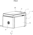
- FIG. 8 is a perspective view illustrating an image forming apparatus 100 of a fourth modification. As illustrated in FIG. 8 , an opening of the first duct 22 of the fourth modification that is opened on the back surface 24a side is provided with a discharge louver 31. This improves the design.
- the air flow that passes through the second duct 15 flows in the -Y direction.
- the fan 13 and the intermediate duct 14 may be disposed on the -Y direction side (i.e., the left side) of the discharging space 10, and the air flow that passes through the second duct 15 may flow in the Y direction.
- the first duct 22 be disposed closer to the first side-surface 23a.
Landscapes
- General Physics & Mathematics (AREA)
- Physics & Mathematics (AREA)
- Engineering & Computer Science (AREA)
- Ecology (AREA)
- Atmospheric Sciences (AREA)
- Biodiversity & Conservation Biology (AREA)
- Life Sciences & Earth Sciences (AREA)
- Environmental & Geological Engineering (AREA)
- Environmental Sciences (AREA)
- Multimedia (AREA)
- Signal Processing (AREA)
- Electrophotography Configuration And Component (AREA)
- Control Or Security For Electrophotography (AREA)
- Paper Feeding For Electrophotography (AREA)
Abstract
An image forming apparatus (100) includes a reading unit (2), an image forming unit (1) including an image bearing member (42), a fixing portion (7), and a discharging portion (8) configured to discharge the sheet toward the discharging space (10) in a sheet discharging direction (DD), and a first duct (22) extending in a first direction (X) and configured to communicate an outside surface of the image forming unit (1) to the discharging space (10). The image forming unit (1) includes a second duct (15) which extends in the rotation-axis direction (Y), and through which an air flow cooling the sheet discharged by the discharging portion (8) passes. At least a portion of the first duct (22) is disposed so as to overlap with the second duct (15) in a second direction (Z) orthogonal to both of the first direction (X) and the rotation-axis direction (Y).
Description
- The present invention relates to an image forming apparatus that forms images on sheets.
-
Japanese Patent Application Publication No. 2015-141227 - In addition,
Japanese Patent Application Publication No. 2017-3713 - However, in the image forming apparatus described in
Japanese Patent Application Publication No. 2015-141227 Japanese Patent Application Publication No. 2017-3713 - As described above, if the image defect caused by the remelting of toner and the occurrence of dew condensation are suppressed, the image forming apparatus is upsized. Thus, it has not been possible that suppressing the image defect and the occurrence of dew condensation and downsizing the image forming apparatus are both achieved.
- The present invention in its first aspect provides an image forming apparatus as specified in
claims 1 to 12. - Further features of the present invention will become apparent from the following description of exemplary embodiments with reference to the attached drawings.
-
-
FIG. 1A is a front view illustrating an image forming apparatus. -
FIG. 1B is a cross-sectional view illustrating a cross section taken along a line A-A ofFIG. 1A . -
FIG. 2A is a perspective view illustrating the image forming apparatus. -
FIG. 2B is another perspective view illustrating the image forming apparatus. -
FIG. 3A is a perspective view illustrating an image forming unit in a state where a side cover is removed. -
FIG. 3B is another perspective view illustrating the image forming unit in the state where the side cover is removed. -
FIG. 4A is a perspective view illustrating a dew-condensation adhesion range of an image forming apparatus of a comparative example. -
FIG. 4B is a perspective view illustrating a flow of air flow and a dew-condensation adhesion range of an image forming apparatus of the present embodiment. -
FIG. 5A is a plan view illustrating a first duct and a second duct of the present embodiment. -
FIG. 5B is a plan view illustrating a first duct and a second duct of a first modification. -
FIG. 6A is a front view illustrating an image forming apparatus of a second modification. -
FIG. 6B is a front view illustrating the image forming apparatus of the second modification. -
FIG. 6C is a cross-sectional view illustrating a cross section taken along a line B-B ofFIG. 6B . -
FIG. 7A is a front view illustrating an image forming apparatus of a third modification. -
FIG. 7B is a perspective view illustrating the image forming apparatus of the third modification. -
FIG. 8 is a perspective view illustrating an image forming apparatus of a fourth modification. - Hereinafter, the present embodiment will be described with reference to the accompanying drawings. Note that in the following description, the positional relationship in the up and down direction, the right and left direction, and the front and back direction is expressed with respect to an
image forming apparatus 100 viewed from the front side (that is, viewed inFIG. 1A ). In addition, in the following description, the front and back direction (the front and back direction) of theimage forming apparatus 100 is defined as an X-axis direction, the right and left direction of theimage forming apparatus 100 is defined as a Y-axis direction, and a height direction of theimage forming apparatus 100 is defined as a Z-axis direction. The X-axis direction, the Y-axis direction, and the Z-axis direction are orthogonal to each other. The X-axis direction that serves as a first direction is a direction along a below-described sheet discharging direction DD. In addition, the X-axis direction is parallel to a horizontal direction and is orthogonal to the rotation-axis direction of a below-describedphotosensitive drum 42. The Y-axis direction is the rotation-axis direction of thephotosensitive drum 42 that serves as an image bearing member. The Z-axis direction that serves as a second direction is the height direction of theimage forming apparatus 100, and is parallel to the vertical direction and the gravity direction. Schematic Configuration of Image Forming Apparatus -
FIG. 1A is a front view illustrating theimage forming apparatus 100.FIG. 1B is a cross-sectional view illustrating a cross section taken along a line A-A ofFIG. 1A . Theimage forming apparatus 100 of the present embodiment is an electrophotographic monochrome laser-beam printer, and is a multifunction printer having a document reading function. - Note that examples of the image forming apparatus include a printer, a copying machine, a facsimile, and a multifunction printer; and the image forming apparatus forms images on sheets, used as a recording medium, in accordance with image information sent from an external PC or read from a document. In addition, there is a case in which an apparatus, such as an option feeder or a sheet processing apparatus, is attached to the body of the image forming apparatus that has the image forming function. In this case, the whole system in which the apparatus is attached to the body is also a type of the image forming apparatus. In addition, the document or the sheet may be a paper sheet, such as a sheet for any purpose or an envelope, a plastic film such as an overhead projector (OHT) sheet, or a cloth sheet.
- As illustrated in
FIGS. 1A and 1B , theimage forming apparatus 100 includes areading unit 2 that reads the image data of a document, and animage forming unit 1 disposed below thereading unit 2. Thereading unit 2 is pivotably supported around an opening-and-closing shaft disposed in an upper and back portion of theimage forming unit 1 so as to be opened and closed with respect to theimage forming unit 1. Thereading unit 2 includes adocument platen glass 2a on which a document is placed, and areading portion 2b which reads the image information of a document placed on thedocument platen glass 2a, by optically scanning the document. Note that thereading unit 2 may include an auto document feeder (ADF) that feeds a document placed on a document tray. The image information is converted into an electrical signal by thereading unit 2, and is sent to a control portion (not illustrated) disposed in theimage forming unit 1. - The
image forming unit 1 includes a feedingportion 5 that feeds a sheet P, animage forming portion 40 that forms an image on the sheet P, a fixingportion 7 that fixes the image to the sheet P, a dischargingroller pair 8 that serves as a discharging portion, and the like. In addition, a dischargingspace 10 is formed between thereading unit 2 and theimage forming unit 1, and the sheet P is discharged to the dischargingspace 10. In the dischargingspace 10, a dischargingtray 9 is disposed, and the sheet P discharged to the dischargingspace 10 is stacked on the dischargingtray 9. - The
image forming portion 40 includes alaser scanner 41, thephotosensitive drum 42, a charging roller (not illustrated), a developing roller (not illustrated), and atransfer roller 43. The charging roller and the developing roller are disposed around thephotosensitive drum 42. Thetransfer roller 43, together with thephotosensitive drum 42, forms a transfer nip 6. - Next, an image forming operation of the
image forming apparatus 100 configured in this manner will be described. If the image data sent from a personal computer (not illustrated) or the like, or read by thereading unit 2 is inputted into thelaser scanner 41, thephotosensitive drum 42 is irradiated with a laser beam emitted from thelaser scanner 41 and corresponding to the image data. - In this case, since the surface of the
photosensitive drum 42 is uniformly charged in advance by the charging roller so as to have a predetermined polarity and potential, an electrostatic latent image is formed on the surface when the surface is irradiated with the laser beam from thelaser scanner 41. The electrostatic latent image formed on thephotosensitive drum 42 is developed by the developing roller, and a toner image is formed on thephotosensitive drum 42. - In parallel with the image forming process, a sheet P placed on a
sheet tray 5a of the feedingportion 5 is fed to a conveyance path CP by apickup roller 5b. The toner image formed on thephotosensitive drum 42 is transferred, at the transfer nip 6, onto the sheet P fed by thepickup roller 5b, by the transfer bias applied to thetransfer roller 43. The sheet P onto which the toner image has been transferred is then applied with predetermined heat and pressure by the fixingportion 7, so that the toner is melted and solidifies (fixed). The sheet P having passed through the fixingportion 7 is discharged to the dischargingtray 9 by the dischargingroller pair 8. - Next, the discharging
space 10 will be described with reference toFIGS. 1A to 2B .FIG. 2A is a perspective view illustrating theimage forming apparatus 100.FIG. 2B is another perspective view illustrating theimage forming apparatus 100. Note that inFIGS. 2A and 2B , thereading unit 2 is opened with respect to theimage forming unit 1. - As illustrated in
FIGS. 1A and 1B , the dischargingspace 10, to which the sheet P is discharged in the sheet discharging direction DD, is formed between theimage forming unit 1 and thereading unit 2. In a state where thereading unit 2 is closed with respect to theimage forming unit 1, the dischargingspace 10 is covered by theimage forming unit 1 and thereading unit 2, except for anopening portion 3 of theimage forming apparatus 100 on the front side. - More specifically, as illustrated in
FIGS. 2A and 2B , the dischargingspace 10 is formed by the dischargingtray 9, on which the discharged sheet P is stacked, a risingsurface 51, a first side-surface 23a, a second side-surface 23b, and abottom surface 11 of thereading unit 2. The risingsurface 51 extends in the Y-axis direction and the Z-axis direction. In the risingsurface 51, asheet discharge port 51a, through which the sheet P discharged by the dischargingroller pair 8 passes, is formed. - The discharging
tray 9 that serves as a stacking surface extends upward as the dischargingtray 9 extends downstream in the sheet discharging direction DD. The first side-surface 23a is formed on a first side (i.e., the right side) of the dischargingtray 9 in the Y-axis direction, and extends in the X-axis direction and the Z-axis direction. The second side-surface 23b is formed on a second side (i.e., the left side) of the dischargingtray 9 in the Y-axis direction, and extends in the X-axis direction and the Z-axis direction. In the first side-surface 23a, a side-surface opening 25 that serves as a second discharge port is formed. - In addition, the
image forming unit 1 includes aside cover 24 that forms an exterior surface. As illustrated inFIG. 1B , theside cover 24 includes aback surface 24a that serves as an outside surface of theimage forming unit 1 on the upstream side in the sheet discharging direction DD. In the right side-surface of theside cover 24, anintake louver 28 having a plurality of holes is formed. Theimage forming unit 1 also includes atop cover 52 that forms a top surface of theimage forming unit 1. In thetop cover 52, aconcave portion 52a is formed, and theconcave portion 52a is concaved so as to be separated from thebottom surface 11 of thereading unit 2. Theconcave portion 52a and thebottom surface 11 of thereading unit 2 form afirst duct 22 that extends in the X-axis direction. Thefirst duct 22 communicates the dischargingspace 10 with theback surface 24a of theimage forming unit 1. - In the Y-axis direction, a width L1 of the
first duct 22 is smaller than a width L2 of the dischargingtray 9. Thefirst duct 22 is disposed at a position closer to the second side-surface 23b than to the first side-surface 23a in the Y-axis direction. More specifically, thefirst duct 22 is formed such that one end surface of thefirst duct 22 in the Y-axis direction is flush with the second side-surface 23b. - Next, a structure of a duct formed in the
image forming unit 1 and a flow of air flow will be described with reference toFIGS. 3A to 4B .FIG. 3A is a perspective view illustrating theimage forming unit 1 in a state where theside cover 24 is removed.FIG. 3B is another perspective view illustrating theimage forming unit 1 in the state where theside cover 24 is removed.FIG. 4A is a perspective view illustrating a dew-condensation adhesion range of animage forming apparatus 200 of a comparative example.FIG. 4B is a perspective view illustrating a flow of air flow and a dew-condensation adhesion range of theimage forming apparatus 100 of the present embodiment. - As illustrated in
FIG. 3A , theimage forming unit 1 includes afan 13, anintermediate duct 14, and asecond duct 15. Note that a direction from the first side-surface 23a (seeFIG. 2A ) toward the second side-surface 23b (seeFIG. 2B ) in the Y-axis direction is defined as a -Y direction that serves as a first axis direction. Thefan 13 and theintermediate duct 14 are disposed upstream of the dischargingspace 10 in the -Y direction. For example, thefan 13 and theintermediate duct 14 are fixed to aside plate 53 that is a part of a frame of theimage forming unit 1. - The
fan 13 sends air flow toward theintermediate duct 14. Theintermediate duct 14 that serves as a third duct extends in the Z-axis direction. Note that although thefan 13 is a centrifugal fan in the present embodiment, the present disclosure is not limited to this. For example, thefan 13 may be an axial-flow fan that sends air flow along the rotation-axis direction of the blade portion. - The air (outside air) taken in from the intake louver 28 (see
FIG. 2B ) by thefan 13 flows in theintermediate duct 14, as indicated by an arrow A. As illustrated inFIG. 3B , at an upper end portion of theintermediate duct 14, abranch portion 17 is disposed for branching the air flow generated by thefan 13. The air flow that has flowed in theintermediate duct 14 is divided, by thebranch portion 17, into the air flow that flows toward thesecond duct 15 in a direction indicated by an arrow B, and into the air flow that flows in a direction indicated by an arrow C, toward the side-surface opening 25 formed in the first side-surface 23a, through a side-surface discharge port 19 formed in an upper end portion of theintermediate duct 14. That is, theintermediate duct 14 guides part of the air flow generated by thefan 13, to thesecond duct 15. - The
second duct 15 extends in the Y-axis direction, and the air flow for cooling the sheet to be discharged by the dischargingroller pair 8 flows in thesecond duct 15. More specifically, the air flow that will flow from the upper end portion of theintermediate duct 14 toward the above-described direction indicated by the arrow B flows into thesecond duct 15, and the air flow flows in thesecond duct 15 toward the -Y direction. In other words, thefan 13 generates the air flow that flows in thesecond duct 15 toward the -Y direction. - The direction of the air flow that flows in the -Y direction in the
second duct 15 is changed to a direction along the sheet discharging direction DD, by a plurality of rectifyingplates 16 disposed in thesecond duct 15. In the risingsurface 51, acooling discharge port 18 that communicates thesecond duct 15 with the dischargingspace 10 is formed. Thecooling discharge port 18 that serves as a first discharge port may be formed integrally with, or separated from thesheet discharge port 51a (seeFIG. 2A ). - The air flow whose direction has been changed to the direction along the sheet discharging direction DD by the plurality of rectifying
plates 16 passes through thecooling discharge port 18, and is discharged toward the dischargingspace 10 in a direction indicated by an arrow D. The air flow discharged, in this manner, toward the dischargingspace 10 in the direction indicated by the arrow D is defined as a first air flow. The first air flow cools the sheet P discharged to the dischargingspace 10 by the dischargingroller pair 8. The sheet P cooled by the first air flow and discharged to the dischargingspace 10 is stacked on the dischargingtray 9. - Since the sheet P stacked on the discharging
tray 9 is cooled by the first air flow, the temperature of the toner becomes equal to or lower than the remelting temperature of the toner. Thus, the sticking of sheets and the image defect caused by the remelting of toner can be suppressed. Note that the air flow that flows in the -Y direction in thesecond duct 15 may cool the sheet P in theimage forming unit 1 before the sheet P is discharged to the dischargingspace 10. That is, thecooling discharge port 18 may discharge the air flow that is generated in thesecond duct 15, and that cools the sheet P to be conveyed by the dischargingroller pair 8. - On the other hand, the air flow that is branched by the
branch portion 17, and that flows in a direction indicated by an arrow C is discharged from the side-surface opening 25 toward the dischargingspace 10 in a direction indicated by an arrow E. The air flow that flows, in this manner, in the direction indicated by the arrow E is defined as a second air flow. The direction indicated by the arrow E is a direction along the -Y direction, and the second air flow (E) merges with the first air flow (D) in the dischargingspace 10. If the air flow into which the second air flow merges with the first air flow is defined as a third air flow, the third air flow flows in a direction indicated by an arrow F, as illustrated inFIG. 4B . - For comparison, an
image forming apparatus 200 of a comparative example, as illustrated inFIG. 4A , will be described. Theimage forming apparatus 200 does not include the above-describedfirst duct 22 and side-surface opening 25 of the present embodiment. Thus, in theimage forming apparatus 200, only the above-described first air flow (D) serves as the cooling air flow for cooling the sheet P, and the first air flow is discharged to the dischargingspace 10 in the direction indicated by the arrow D. In this case, the dischargingspace 10 is filled with the water vapor produced in the fixingportion 7 and the water vapor produced from the sheet P. - Since the
image forming apparatus 200 does not include thefirst duct 22, the water vapor that fills the dischargingspace 10 adheres, as dew condensation, to thebottom surface 11 of thereading unit 2. The dew-condensation adhesion range hatched inFIG. 4A is almost equal to the whole range of thebottom surface 11 that forms the dischargingspace 10. - On the other hand, in the present embodiment, as illustrated in
FIG. 4B , the third air flow, indicated by the arrow F and produced by the first air flow (D) and the second air flow (E) merging each other, abuts against the second side-surface 23b. This is because the second air flow (E) flows in the -Y direction. A part of the air flow that has abutted against the second side-surface 23b passes through thefirst duct 22 and is discharged toward theback surface 24a of theimage forming unit 1. Another part of the air flow flows along the second side-surface 23b and is discharged from the opening portion 3 (seeFIG. 1B ) of theimage forming apparatus 100 on the front side. - As a result, the resulting dew-condensation adhesion range of the present embodiment, hatched in
FIG. 4B , is divided into the second side-surface 23b, thefirst duct 22, and part of thereading unit 2. The dew-condensation adhesion range is formed only on the -Y direction side (i.e., the left side) of the dischargingspace 10, but is not formed on the Y direction side (i.e., the right side) of the dischargingspace 10. In addition, each of a dew-condensation adhesion range formed in thebottom surface 11 of thereading unit 2 and a dew-condensation adhesion range formed on the front side is smaller than the corresponding dew-condensation adhesion range of the comparative example illustrated inFIG. 4A . Thus, the risk that the dew condensation will adhere to a user or the sheet P discharged by the dischargingroller pair 8 can be reduced, and the reduction in image defect and the improvement in usability can be achieved. - Next, arrangement of the
first duct 22 and thesecond duct 15 will be described with reference toFIG. 1A andFIGS. 5A and 5B. FIG. 5A is a plan view illustrating thefirst duct 22 and thesecond duct 15 of the present embodiment.FIG. 5B is a plan view illustrating afirst duct 22 and asecond duct 15 of a first modification. - As illustrated in
FIG. 1A , in the present embodiment, thefirst duct 22 is disposed at a position whose height is equal to the height of the position of thesecond duct 15 in the Z-axis direction. Note that although the height of the position of thefirst duct 22 and the height of the position of thesecond duct 15 are equal to each other in the present embodiment, at least a portion of thefirst duct 22 has only to overlap with thesecond duct 15 in the Z-axis direction. In addition, as illustrated inFIG. 5A , thefirst duct 22 is formed so as not to overlap with thesecond duct 15 in the Y-axis direction. That is, thefirst duct 22 is disposed, side by side, with thesecond duct 15 in the Y-axis direction. - By arranging the
first duct 22 and thesecond duct 15 as described above, theimage forming apparatus 100 can be downsized, especially in the Z-axis direction. In addition, since the sheet P can be cooled by the air flow that flows through thesecond duct 15, the image defect caused by the remelting of toner can be reduced. In addition, since thefirst duct 22 is formed in theimage forming apparatus 100, and the second air flow (E) that flows from the side-surface opening 25 in the -Y direction is merged with the first air flow (D) that flows in the direction indicated by the arrow D, the dew-condensation adhesion range can be reduced, and the occurrence of dew condensation can be suppressed. That is, suppressing the image defect and the occurrence of dew condensation, and downsizing theimage forming apparatus 100 can be both achieved. - In addition, since convection (F) is produced, by force, by merging the second air flow (E) that flows in the -Y direction with the first air flow (D) that flows in the direction indicated by the arrow D, the cross-sectional area of the
first duct 22 can be reduced. In addition, since theimage forming apparatus 100 can be downsized, the flexibility in installation location for a user can be increased, and the usability can be improved. - In a first modification illustrated in
FIG. 5B , the shape of thefirst duct 22 is changed. That is, in thefirst duct 22 illustrated inFIG. 5B , the side of thefirst duct 22 that communicates with the dischargingspace 10 is increased in the Y-axis direction. That is, a portion G of thefirst duct 22 is formed so as to overlap with thesecond duct 15 in the Y-axis direction. With this structure, the amount of air flow that flows from the dischargingspace 10 into thefirst duct 22 increases, so that the occurrence of image defect and dew condensation can be further suppressed. Second Modification -
FIG. 6A is a front view illustrating animage forming apparatus 100 of a second modification.FIG. 6B is a front view illustrating theimage forming apparatus 100 of the second modification.FIG. 6C is a cross-sectional view illustrating a cross section taken along a line B-B ofFIG. 6B . - As illustrated in
FIGS. 6A to 6C , in the second modification, a readingconcave portion 30 is formed in thebottom surface 11 of thereading unit 2. The readingconcave portion 30 is concaved so as to be separated from thetop cover 52 of theimage forming unit 1. In addition, the readingconcave portion 30 faces theconcave portion 52a of thetop cover 52, and the readingconcave portion 30 is disposed such that at least a portion of the readingconcave portion 30 overlaps with theconcave portion 52a in the Y-axis direction. - In addition, the
first duct 22 of the second modification is formed by theconcave portion 52a and the readingconcave portion 30. Thus, the cross-sectional area of thefirst duct 22 of the second modification can be made larger than the cross-sectional area of the first duct 22 (seeFIG. 1A ) of the present embodiment. As a result, the amount of air flow that flows from the dischargingspace 10 into thefirst duct 22 increases, and the occurrence of image defect and dew condensation can be further suppressed. -
FIG. 7A is a front view illustrating animage forming apparatus 100 of a third modification.FIG. 7B is a perspective view illustrating theimage forming apparatus 100 of the third modification. In the third modification, as illustrated inFIGS. 7A and 7B , a readingconcave portion 130 is formed in thebottom surface 11 of thereading unit 2. The readingconcave portion 130 is concaved so as to be separated from thetop cover 52 of theimage forming unit 1. - The reading
concave portion 130 is shifted from the readingconcave portion 30 of the second modification in the Y-axis direction. However, the readingconcave portion 130 also faces theconcave portion 52a of thetop cover 52, and the readingconcave portion 130 is disposed such that at least a portion of the readingconcave portion 130 overlaps with theconcave portion 52a in the Y-axis direction. Thus, the same effects as those of the second modification can be produced, and the flexibility in design can be improved. -
FIG. 8 is a perspective view illustrating animage forming apparatus 100 of a fourth modification. As illustrated inFIG. 8 , an opening of thefirst duct 22 of the fourth modification that is opened on theback surface 24a side is provided with adischarge louver 31. This improves the design. - In the present embodiment, the air flow that passes through the
second duct 15 flows in the -Y direction. However, the present disclosure is not limited to this. For example, thefan 13 and theintermediate duct 14 may be disposed on the -Y direction side (i.e., the left side) of the dischargingspace 10, and the air flow that passes through thesecond duct 15 may flow in the Y direction. In this case, it is preferable that thefirst duct 22 be disposed closer to the first side-surface 23a. - While the present invention has been described with reference to exemplary embodiments, it is to be understood that the invention is not limited to the disclosed exemplary embodiments. The scope of the following claims is to be accorded the broadest interpretation so as to encompass all such modifications and equivalent structures and functions.
Claims (12)
- An image forming apparatus (100) comprising:a reading unit (2) including a reading portion (2b) configured to read an image of a document;an image forming unit (1) disposed below the reading unit (2) and configured to form a discharging space (10) between the reading unit (2) and the image forming unit (1), the image forming unit (1) including:an image bearing member (42) configured to bear a toner image to be transferred to a sheet;a fixing portion (7) configured to fix the toner image to the sheet by applying heat and pressure to the sheet; anda discharging portion (8) configured to discharge the sheet, that has passed through the fixing portion (7), toward the discharging space (10) in a sheet discharging direction (DD); anda first duct (22) extending in a first direction (X) and configured to communicate an outside surface of the image forming unit (1) to the discharging space (10), the first direction (X) being along the sheet discharging direction (DD) and orthogonal to a rotation-axis direction (Y) of the image bearing member (42), the outside surface being formed on an upstream side of the image forming unit (1) in the sheet discharging direction (DD),wherein the image forming unit (1) includes a second duct (15) which extends in the rotation-axis direction (Y), and through which an air flow cooling the sheet discharged by the discharging portion (8) passes, andwherein at least a portion of the first duct (22) is disposed so as to overlap with the second duct (15) in a second direction (Z) orthogonal to both of the first direction (X) and the rotation-axis direction (Y).
- The image forming apparatus (100) according to claim 1, wherein the image forming unit (1) includes:a stacking surface (9) on which the sheet discharged by the discharging portion (8) is stacked;a rising surface (51) in which a sheet discharge port (51a) is formed, and which extends in both of the rotation-axis direction (Y) and the second direction (Z), the sheet discharge port (51a) being a port through which the sheet discharged by the discharging portion (8) passes;a first side-surface (23a) formed on a first side of the stacking surface (9) in the rotation-axis direction (Y); anda second side-surface (23b) formed on a second side of the stacking surface (9) in the rotation-axis direction (Y),wherein the discharging space (10) is formed by the stacking surface (9), the rising surface (51), the first side-surface (23a), the second side-surface (23b), and a bottom surface (11) of the reading unit (2), andwherein a width (L1) of the first duct (22) is smaller than a width (L2) of the stacking surface (9) in the rotation-axis direction (Y).
- The image forming apparatus (100) according to claim 2, wherein the first duct (22) is disposed at a position closer to the second side-surface (23b) than the first side-surface (23a) in the rotation-axis direction (Y).
- The image forming apparatus (100) according to claim 3, wherein when a direction from the first side-surface (23a) toward the second side-surface (23b) in the rotation-axis direction (Y) is a first axis direction (-Y), the image forming unit (1) includes a fan (13) configured to generate an air flow that flows in the second duct (15) in the first axis direction (-Y).
- The image forming apparatus (100) according to claim 4, wherein the rising surface (51) includes a first discharge port (18) configured to communicate the second duct (15) to the discharging space (10) and discharge a first air flow toward the discharging space (10) in the sheet discharging direction (DD), the first air flow cooling the sheet discharged by the discharging portion (8),wherein the first side-surface (23a) includes a second discharge port (25) configured to communicate with the discharging space (10) and discharge a second air flow toward the discharging space (10) in the first axis direction (-Y), the second air flow being a part of the air flow generated by the fan (13), andwherein the first air flow and the second air flow merge in the discharging space (10).
- The image forming apparatus (100) according to claim 5, wherein the image forming unit (1) includes a third duct (14) configured to guide the air flow generated by the fan (13) to the second duct (15), and
wherein the fan (13) and the third duct (14) are disposed upstream of the discharging space (10) in the first axis direction (-Y). - The image forming apparatus (100) according to claim 6, wherein an air flow that flows in the third duct (14) is divided into an air flow that flows toward the second duct (15) and an air flow that flows toward the second discharge port (25).
- The image forming apparatus (100) according to any one of claims 2 to 7, wherein the image forming unit (1) includes:a top cover (52) configured to face the bottom surface (11) of the reading unit (2); anda concave portion (52a) formed in the top cover (52) and concaved so as to be separated from the bottom surface (11), and
wherein the first duct (22) is formed by the bottom surface (11) of the reading unit (2) and the concave portion (52a). - The image forming apparatus (100) according to claim 8, wherein the bottom surface (11) of the reading unit (2) includes a reading concave portion (30) concaved so as to be separated away from the top cover (52) of the image forming unit (1), and
wherein at least a portion of the reading concave portion (30) is disposed so as to overlap with the concave portion (52a) in the rotation-axis direction (Y). - The image forming apparatus (100) according to any one of claims 1 to 9, wherein the first duct (22) is formed so as not to overlap with the second duct (15) in the rotation-axis direction (Y).
- The image forming apparatus (100) according to any one of claims 1 to 9, wherein a portion of the first duct (22) is formed so as to overlap with the second duct (15) in the rotation-axis direction (Y).
- The image forming apparatus (100) according to any one of claims 1 to 11, wherein the first direction (X) is parallel to a horizontal direction and is orthogonal to the rotation-axis direction (Y), and
wherein the second direction (Z) is a direction parallel to a vertical direction.
Applications Claiming Priority (1)
| Application Number | Priority Date | Filing Date | Title |
|---|---|---|---|
| JP2023215202A JP2025098818A (en) | 2023-12-20 | 2023-12-20 | Image forming apparatus |
Publications (1)
| Publication Number | Publication Date |
|---|---|
| EP4575650A1 true EP4575650A1 (en) | 2025-06-25 |
Family
ID=93925782
Family Applications (1)
| Application Number | Title | Priority Date | Filing Date |
|---|---|---|---|
| EP24221563.0A Pending EP4575650A1 (en) | 2023-12-20 | 2024-12-19 | Image forming apparatus |
Country Status (4)
| Country | Link |
|---|---|
| US (1) | US20250208565A1 (en) |
| EP (1) | EP4575650A1 (en) |
| JP (1) | JP2025098818A (en) |
| CN (1) | CN120178626A (en) |
Citations (4)
| Publication number | Priority date | Publication date | Assignee | Title |
|---|---|---|---|---|
| US20070196152A1 (en) * | 2006-02-20 | 2007-08-23 | Keisuke Shimizu | Sheet feeding apparatus and image forming apparatus |
| US20140029999A1 (en) * | 2012-07-30 | 2014-01-30 | Kyocera Document Solutions Inc. | Image forming apparatus including plurality of paper output trays |
| JP2015141227A (en) | 2014-01-27 | 2015-08-03 | キヤノン株式会社 | Image forming apparatus |
| JP2017003713A (en) | 2015-06-08 | 2017-01-05 | キヤノン株式会社 | Image forming apparatus |
Family Cites Families (9)
| Publication number | Priority date | Publication date | Assignee | Title |
|---|---|---|---|---|
| US6438339B1 (en) * | 2000-12-18 | 2002-08-20 | Toshiba Tec Kabushiki Kaisha | Image forming apparatus with a blower to cool a scanning unit |
| JP4760602B2 (en) * | 2005-11-11 | 2011-08-31 | 富士ゼロックス株式会社 | Image forming apparatus |
| JP4760601B2 (en) * | 2005-12-16 | 2011-08-31 | 富士ゼロックス株式会社 | Image forming apparatus |
| JP6265691B2 (en) * | 2013-11-08 | 2018-01-24 | キヤノン株式会社 | Image forming apparatus |
| JP6528988B2 (en) * | 2015-04-28 | 2019-06-12 | 株式会社リコー | Image forming device |
| US10317841B2 (en) * | 2015-06-08 | 2019-06-11 | Canon Kabushiki Kaisha | Image forming apparatus |
| JP7047342B2 (en) * | 2017-11-22 | 2022-04-05 | 京セラドキュメントソリューションズ株式会社 | Image forming device |
| JP2022018972A (en) * | 2020-07-16 | 2022-01-27 | 京セラドキュメントソリューションズ株式会社 | Blower device for image formation and image forming apparatus |
| JP7639402B2 (en) * | 2021-03-01 | 2025-03-05 | 京セラドキュメントソリューションズ株式会社 | Image forming device |
-
2023
- 2023-12-20 JP JP2023215202A patent/JP2025098818A/en active Pending
-
2024
- 2024-12-17 CN CN202411854805.2A patent/CN120178626A/en active Pending
- 2024-12-18 US US18/985,853 patent/US20250208565A1/en active Pending
- 2024-12-19 EP EP24221563.0A patent/EP4575650A1/en active Pending
Patent Citations (4)
| Publication number | Priority date | Publication date | Assignee | Title |
|---|---|---|---|---|
| US20070196152A1 (en) * | 2006-02-20 | 2007-08-23 | Keisuke Shimizu | Sheet feeding apparatus and image forming apparatus |
| US20140029999A1 (en) * | 2012-07-30 | 2014-01-30 | Kyocera Document Solutions Inc. | Image forming apparatus including plurality of paper output trays |
| JP2015141227A (en) | 2014-01-27 | 2015-08-03 | キヤノン株式会社 | Image forming apparatus |
| JP2017003713A (en) | 2015-06-08 | 2017-01-05 | キヤノン株式会社 | Image forming apparatus |
Also Published As
| Publication number | Publication date |
|---|---|
| US20250208565A1 (en) | 2025-06-26 |
| JP2025098818A (en) | 2025-07-02 |
| CN120178626A (en) | 2025-06-20 |
Similar Documents
| Publication | Publication Date | Title |
|---|---|---|
| US8014696B2 (en) | Image forming device | |
| US10503118B2 (en) | Image forming apparatus having air cooling system | |
| CN112506018B (en) | Image forming apparatus having a plurality of image forming units | |
| US9946223B2 (en) | Cooling device and image forming apparatus incorporating the cooling device | |
| US11086248B2 (en) | Image forming apparatus with fan configured for dust-resistant cooling of optical scanning unit | |
| US11209771B2 (en) | Image forming apparatus | |
| US20250208565A1 (en) | Image forming apparatus | |
| JP2008185896A (en) | Image forming apparatus | |
| JP4773699B2 (en) | Image forming apparatus | |
| JP4359523B2 (en) | Image forming apparatus | |
| JP2017015783A (en) | Cooling apparatus, and image processing device | |
| US7693444B2 (en) | Image reading and recording apparatus having a cartridge dismounting space between a fixing unit and an exposing unit | |
| US20260044109A1 (en) | Structure for releasing heat generated inside of image forming apparatus | |
| US9304471B2 (en) | Image forming apparatus, discharge tray used in image forming apparatus | |
| CN219392475U (en) | Image forming apparatus with a plurality of image forming units | |
| US20240305725A1 (en) | Image forming apparatus | |
| US20250138472A1 (en) | Image forming apparatus | |
| JP4841965B2 (en) | Image forming apparatus | |
| JP2004160747A (en) | Image forming device | |
| JP5365493B2 (en) | Image forming apparatus | |
| JP2001353928A (en) | Image forming device | |
| JP2004037685A (en) | Image forming device | |
| JP4397734B2 (en) | Developing device and image forming apparatus | |
| JP6525258B2 (en) | Optical scanning device and image forming apparatus | |
| JP2006139219A (en) | Image forming apparatus |
Legal Events
| Date | Code | Title | Description |
|---|---|---|---|
| PUAI | Public reference made under article 153(3) epc to a published international application that has entered the european phase |
Free format text: ORIGINAL CODE: 0009012 |
|
| STAA | Information on the status of an ep patent application or granted ep patent |
Free format text: STATUS: THE APPLICATION HAS BEEN PUBLISHED |
|
| AK | Designated contracting states |
Kind code of ref document: A1 Designated state(s): AL AT BE BG CH CY CZ DE DK EE ES FI FR GB GR HR HU IE IS IT LI LT LU LV MC ME MK MT NL NO PL PT RO RS SE SI SK SM TR |
|
| STAA | Information on the status of an ep patent application or granted ep patent |
Free format text: STATUS: REQUEST FOR EXAMINATION WAS MADE |
|
| 17P | Request for examination filed |
Effective date: 20260102 |