EP4575539A1 - Battery management system, battery pack, electric vehicle and battery management method - Google Patents
Battery management system, battery pack, electric vehicle and battery management method Download PDFInfo
- Publication number
- EP4575539A1 EP4575539A1 EP24832174.7A EP24832174A EP4575539A1 EP 4575539 A1 EP4575539 A1 EP 4575539A1 EP 24832174 A EP24832174 A EP 24832174A EP 4575539 A1 EP4575539 A1 EP 4575539A1
- Authority
- EP
- European Patent Office
- Prior art keywords
- battery
- current
- soc
- state
- charge
- Prior art date
- Legal status (The legal status is an assumption and is not a legal conclusion. Google has not performed a legal analysis and makes no representation as to the accuracy of the status listed.)
- Pending
Links
Images






Classifications
-
- G—PHYSICS
- G01—MEASURING; TESTING
- G01R—MEASURING ELECTRIC VARIABLES; MEASURING MAGNETIC VARIABLES
- G01R31/00—Arrangements for testing electric properties; Arrangements for locating electric faults; Arrangements for electrical testing characterised by what is being tested not provided for elsewhere
- G01R31/36—Arrangements for testing, measuring or monitoring the electrical condition of accumulators or electric batteries, e.g. capacity or state of charge [SoC]
- G01R31/382—Arrangements for monitoring battery or accumulator variables, e.g. SoC
-
- B—PERFORMING OPERATIONS; TRANSPORTING
- B60—VEHICLES IN GENERAL
- B60L—PROPULSION OF ELECTRICALLY-PROPELLED VEHICLES; SUPPLYING ELECTRIC POWER FOR AUXILIARY EQUIPMENT OF ELECTRICALLY-PROPELLED VEHICLES; ELECTRODYNAMIC BRAKE SYSTEMS FOR VEHICLES IN GENERAL; MAGNETIC SUSPENSION OR LEVITATION FOR VEHICLES; MONITORING OPERATING VARIABLES OF ELECTRICALLY-PROPELLED VEHICLES; ELECTRIC SAFETY DEVICES FOR ELECTRICALLY-PROPELLED VEHICLES
- B60L58/00—Methods or circuit arrangements for monitoring or controlling batteries or fuel cells, specially adapted for electric vehicles
- B60L58/10—Methods or circuit arrangements for monitoring or controlling batteries or fuel cells, specially adapted for electric vehicles for monitoring or controlling batteries
- B60L58/12—Methods or circuit arrangements for monitoring or controlling batteries or fuel cells, specially adapted for electric vehicles for monitoring or controlling batteries responding to state of charge [SoC]
-
- B—PERFORMING OPERATIONS; TRANSPORTING
- B60—VEHICLES IN GENERAL
- B60L—PROPULSION OF ELECTRICALLY-PROPELLED VEHICLES; SUPPLYING ELECTRIC POWER FOR AUXILIARY EQUIPMENT OF ELECTRICALLY-PROPELLED VEHICLES; ELECTRODYNAMIC BRAKE SYSTEMS FOR VEHICLES IN GENERAL; MAGNETIC SUSPENSION OR LEVITATION FOR VEHICLES; MONITORING OPERATING VARIABLES OF ELECTRICALLY-PROPELLED VEHICLES; ELECTRIC SAFETY DEVICES FOR ELECTRICALLY-PROPELLED VEHICLES
- B60L53/00—Methods of charging batteries, specially adapted for electric vehicles; Charging stations or on-board charging equipment therefor; Exchange of energy storage elements in electric vehicles
- B60L53/20—Methods of charging batteries, specially adapted for electric vehicles; Charging stations or on-board charging equipment therefor; Exchange of energy storage elements in electric vehicles characterised by converters located in the vehicle
- B60L53/24—Using the vehicle's propulsion converter for charging
-
- G—PHYSICS
- G01—MEASURING; TESTING
- G01R—MEASURING ELECTRIC VARIABLES; MEASURING MAGNETIC VARIABLES
- G01R19/00—Arrangements for measuring currents or voltages or for indicating presence or sign thereof
- G01R19/12—Measuring rate of change
-
- G—PHYSICS
- G01—MEASURING; TESTING
- G01R—MEASURING ELECTRIC VARIABLES; MEASURING MAGNETIC VARIABLES
- G01R31/00—Arrangements for testing electric properties; Arrangements for locating electric faults; Arrangements for electrical testing characterised by what is being tested not provided for elsewhere
- G01R31/36—Arrangements for testing, measuring or monitoring the electrical condition of accumulators or electric batteries, e.g. capacity or state of charge [SoC]
- G01R31/3644—Constructional arrangements
- G01R31/3648—Constructional arrangements comprising digital calculation means, e.g. for performing an algorithm
-
- G—PHYSICS
- G01—MEASURING; TESTING
- G01R—MEASURING ELECTRIC VARIABLES; MEASURING MAGNETIC VARIABLES
- G01R31/00—Arrangements for testing electric properties; Arrangements for locating electric faults; Arrangements for electrical testing characterised by what is being tested not provided for elsewhere
- G01R31/36—Arrangements for testing, measuring or monitoring the electrical condition of accumulators or electric batteries, e.g. capacity or state of charge [SoC]
- G01R31/367—Software therefor, e.g. for battery testing using modelling or look-up tables
-
- G—PHYSICS
- G01—MEASURING; TESTING
- G01R—MEASURING ELECTRIC VARIABLES; MEASURING MAGNETIC VARIABLES
- G01R31/00—Arrangements for testing electric properties; Arrangements for locating electric faults; Arrangements for electrical testing characterised by what is being tested not provided for elsewhere
- G01R31/36—Arrangements for testing, measuring or monitoring the electrical condition of accumulators or electric batteries, e.g. capacity or state of charge [SoC]
- G01R31/382—Arrangements for monitoring battery or accumulator variables, e.g. SoC
- G01R31/3828—Arrangements for monitoring battery or accumulator variables, e.g. SoC using current integration
-
- G—PHYSICS
- G01—MEASURING; TESTING
- G01R—MEASURING ELECTRIC VARIABLES; MEASURING MAGNETIC VARIABLES
- G01R31/00—Arrangements for testing electric properties; Arrangements for locating electric faults; Arrangements for electrical testing characterised by what is being tested not provided for elsewhere
- G01R31/36—Arrangements for testing, measuring or monitoring the electrical condition of accumulators or electric batteries, e.g. capacity or state of charge [SoC]
- G01R31/382—Arrangements for monitoring battery or accumulator variables, e.g. SoC
- G01R31/3842—Arrangements for monitoring battery or accumulator variables, e.g. SoC combining voltage and current measurements
-
- G—PHYSICS
- G01—MEASURING; TESTING
- G01R—MEASURING ELECTRIC VARIABLES; MEASURING MAGNETIC VARIABLES
- G01R31/00—Arrangements for testing electric properties; Arrangements for locating electric faults; Arrangements for electrical testing characterised by what is being tested not provided for elsewhere
- G01R31/36—Arrangements for testing, measuring or monitoring the electrical condition of accumulators or electric batteries, e.g. capacity or state of charge [SoC]
- G01R31/385—Arrangements for measuring battery or accumulator variables
-
- G—PHYSICS
- G01—MEASURING; TESTING
- G01R—MEASURING ELECTRIC VARIABLES; MEASURING MAGNETIC VARIABLES
- G01R31/00—Arrangements for testing electric properties; Arrangements for locating electric faults; Arrangements for electrical testing characterised by what is being tested not provided for elsewhere
- G01R31/36—Arrangements for testing, measuring or monitoring the electrical condition of accumulators or electric batteries, e.g. capacity or state of charge [SoC]
- G01R31/396—Acquisition or processing of data for testing or for monitoring individual cells or groups of cells within a battery
-
- H—ELECTRICITY
- H01—ELECTRIC ELEMENTS
- H01M—PROCESSES OR MEANS, e.g. BATTERIES, FOR THE DIRECT CONVERSION OF CHEMICAL ENERGY INTO ELECTRICAL ENERGY
- H01M10/00—Secondary cells; Manufacture thereof
- H01M10/42—Methods or arrangements for servicing or maintenance of secondary cells or secondary half-cells
- H01M10/425—Structural combination with electronic components, e.g. electronic circuits integrated to the outside of the casing
-
- H—ELECTRICITY
- H01—ELECTRIC ELEMENTS
- H01M—PROCESSES OR MEANS, e.g. BATTERIES, FOR THE DIRECT CONVERSION OF CHEMICAL ENERGY INTO ELECTRICAL ENERGY
- H01M10/00—Secondary cells; Manufacture thereof
- H01M10/42—Methods or arrangements for servicing or maintenance of secondary cells or secondary half-cells
- H01M10/44—Methods for charging or discharging
-
- H—ELECTRICITY
- H01—ELECTRIC ELEMENTS
- H01M—PROCESSES OR MEANS, e.g. BATTERIES, FOR THE DIRECT CONVERSION OF CHEMICAL ENERGY INTO ELECTRICAL ENERGY
- H01M10/00—Secondary cells; Manufacture thereof
- H01M10/42—Methods or arrangements for servicing or maintenance of secondary cells or secondary half-cells
- H01M10/48—Accumulators combined with arrangements for measuring, testing or indicating the condition of cells, e.g. the level or density of the electrolyte
-
- H—ELECTRICITY
- H02—GENERATION; CONVERSION OR DISTRIBUTION OF ELECTRIC POWER
- H02J—ELECTRIC POWER NETWORKS; CIRCUIT ARRANGEMENTS OR SYSTEMS FOR SUPPLYING OR DISTRIBUTING ELECTRIC POWER; SYSTEMS FOR STORING ELECTRIC ENERGY
- H02J7/00—Circuit arrangements for charging or discharging batteries or for supplying loads from batteries
- H02J7/80—Circuit arrangements for charging or discharging batteries or for supplying loads from batteries including monitoring or indicating arrangements
- H02J7/82—Control of state of charge [SOC]
-
- B—PERFORMING OPERATIONS; TRANSPORTING
- B60—VEHICLES IN GENERAL
- B60L—PROPULSION OF ELECTRICALLY-PROPELLED VEHICLES; SUPPLYING ELECTRIC POWER FOR AUXILIARY EQUIPMENT OF ELECTRICALLY-PROPELLED VEHICLES; ELECTRODYNAMIC BRAKE SYSTEMS FOR VEHICLES IN GENERAL; MAGNETIC SUSPENSION OR LEVITATION FOR VEHICLES; MONITORING OPERATING VARIABLES OF ELECTRICALLY-PROPELLED VEHICLES; ELECTRIC SAFETY DEVICES FOR ELECTRICALLY-PROPELLED VEHICLES
- B60L2240/00—Control parameters of input or output; Target parameters
- B60L2240/40—Drive Train control parameters
- B60L2240/54—Drive Train control parameters related to batteries
- B60L2240/545—Temperature
-
- B—PERFORMING OPERATIONS; TRANSPORTING
- B60—VEHICLES IN GENERAL
- B60L—PROPULSION OF ELECTRICALLY-PROPELLED VEHICLES; SUPPLYING ELECTRIC POWER FOR AUXILIARY EQUIPMENT OF ELECTRICALLY-PROPELLED VEHICLES; ELECTRODYNAMIC BRAKE SYSTEMS FOR VEHICLES IN GENERAL; MAGNETIC SUSPENSION OR LEVITATION FOR VEHICLES; MONITORING OPERATING VARIABLES OF ELECTRICALLY-PROPELLED VEHICLES; ELECTRIC SAFETY DEVICES FOR ELECTRICALLY-PROPELLED VEHICLES
- B60L2240/00—Control parameters of input or output; Target parameters
- B60L2240/40—Drive Train control parameters
- B60L2240/54—Drive Train control parameters related to batteries
- B60L2240/547—Voltage
-
- B—PERFORMING OPERATIONS; TRANSPORTING
- B60—VEHICLES IN GENERAL
- B60L—PROPULSION OF ELECTRICALLY-PROPELLED VEHICLES; SUPPLYING ELECTRIC POWER FOR AUXILIARY EQUIPMENT OF ELECTRICALLY-PROPELLED VEHICLES; ELECTRODYNAMIC BRAKE SYSTEMS FOR VEHICLES IN GENERAL; MAGNETIC SUSPENSION OR LEVITATION FOR VEHICLES; MONITORING OPERATING VARIABLES OF ELECTRICALLY-PROPELLED VEHICLES; ELECTRIC SAFETY DEVICES FOR ELECTRICALLY-PROPELLED VEHICLES
- B60L2240/00—Control parameters of input or output; Target parameters
- B60L2240/40—Drive Train control parameters
- B60L2240/54—Drive Train control parameters related to batteries
- B60L2240/549—Current
-
- B—PERFORMING OPERATIONS; TRANSPORTING
- B60—VEHICLES IN GENERAL
- B60L—PROPULSION OF ELECTRICALLY-PROPELLED VEHICLES; SUPPLYING ELECTRIC POWER FOR AUXILIARY EQUIPMENT OF ELECTRICALLY-PROPELLED VEHICLES; ELECTRODYNAMIC BRAKE SYSTEMS FOR VEHICLES IN GENERAL; MAGNETIC SUSPENSION OR LEVITATION FOR VEHICLES; MONITORING OPERATING VARIABLES OF ELECTRICALLY-PROPELLED VEHICLES; ELECTRIC SAFETY DEVICES FOR ELECTRICALLY-PROPELLED VEHICLES
- B60L2260/00—Operating Modes
- B60L2260/40—Control modes
- B60L2260/42—Control modes by adaptive correction
-
- H—ELECTRICITY
- H01—ELECTRIC ELEMENTS
- H01M—PROCESSES OR MEANS, e.g. BATTERIES, FOR THE DIRECT CONVERSION OF CHEMICAL ENERGY INTO ELECTRICAL ENERGY
- H01M10/00—Secondary cells; Manufacture thereof
- H01M10/42—Methods or arrangements for servicing or maintenance of secondary cells or secondary half-cells
- H01M10/425—Structural combination with electronic components, e.g. electronic circuits integrated to the outside of the casing
- H01M2010/4271—Battery management systems including electronic circuits, e.g. control of current or voltage to keep battery in healthy state, cell balancing
-
- H—ELECTRICITY
- H01—ELECTRIC ELEMENTS
- H01M—PROCESSES OR MEANS, e.g. BATTERIES, FOR THE DIRECT CONVERSION OF CHEMICAL ENERGY INTO ELECTRICAL ENERGY
- H01M2220/00—Batteries for particular applications
- H01M2220/20—Batteries in motive systems, e.g. vehicle, ship, plane
-
- Y—GENERAL TAGGING OF NEW TECHNOLOGICAL DEVELOPMENTS; GENERAL TAGGING OF CROSS-SECTIONAL TECHNOLOGIES SPANNING OVER SEVERAL SECTIONS OF THE IPC; TECHNICAL SUBJECTS COVERED BY FORMER USPC CROSS-REFERENCE ART COLLECTIONS [XRACs] AND DIGESTS
- Y02—TECHNOLOGIES OR APPLICATIONS FOR MITIGATION OR ADAPTATION AGAINST CLIMATE CHANGE
- Y02E—REDUCTION OF GREENHOUSE GAS [GHG] EMISSIONS, RELATED TO ENERGY GENERATION, TRANSMISSION OR DISTRIBUTION
- Y02E60/00—Enabling technologies; Technologies with a potential or indirect contribution to GHG emissions mitigation
- Y02E60/10—Energy storage using batteries
Definitions
- the present disclosure relates to State Of Charge estimation in a battery.
- the SOC is a parameter indicating a relative ratio of the current capacity to the maximum capacity indicating the total electrical energy when the battery is fully charged, and may be represented as 0 to 1 (or 0% to 100%). For example, when the maximum capacity of the battery is 1000 Ah (ampere-hour), and the capacity currently stored in the battery is 750 Ah, the SOC of the battery is 0.75 (or 75%).
- EKF extended Kalman filter
- the extended Kalman filter is an SOC estimation logic using an equivalent circuit model (ECM) and an SOC-Open Circuit Voltage (OCV) curve, each prepared beforehand according to electrical and chemical properties of the battery, and outputs an estimated SOC that is one of state variables when inputting a voltage and a current of the battery as input variables.
- ECM equivalent circuit model
- OCV SOC-Open Circuit Voltage
- LFP lithium iron phosphate
- SOC-OCV SOC-Closed Circuit Voltage
- an approach to estimate the SOC of the battery in a constant current charge/discharge mode using ampere counting rather than EKF may be contemplated.
- the ampere counting refers to the technique that estimates the SOC of the battery by converting an accumulated value of the current flowing through the battery to a change in SOC.
- a current measurement error also accumulates over time, resulting in low accuracy in SOC estimation by ampere counting.
- the present disclosure is designed to solve the above-described problem, and therefore the present disclosure is directed to a battery pack for estimating a state of charge of a battery having a characteristic that a voltage variation section changes depending on a current rate by using two extended Kalman filters having a complementary relationship in parallel, an electric vehicle including the battery pack and a battery management method.
- a battery management system is for a battery having a characteristic that a voltage variation section changes depending on a current rate.
- the battery management system includes a sensing unit configured to detect a terminal voltage and a charge/discharge current of the battery, a memory unit configured to store a first Kalman filter which is a state of charge (SOC) estimation logic using an equivalent circuit model and an SOC-open circuit voltage (OCV) curve of the battery and a second Kalman filter which is an SOC estimation logic using a constant current charge/discharge map of the battery, and a control unit configured to determine a voltage value of the detected terminal voltage and a current value of the detected charge/discharge current.
- SOC state of charge
- OCV SOC-open circuit voltage
- the control unit is configured to determine a first estimated SOC by inputting the voltage value, the current value and an estimated SOC in a previous cycle to the first Kalman filter, and determine a second estimated SOC by inputting the current value and the estimated SOC in the previous cycle to the second Kalman filter.
- the control unit is configured to determine an SOC of the battery in a current cycle based on at least one of the first estimated SOC or the second estimated SOC.
- the control unit may be configured to determine whether the battery is in a first state in which the battery is not being charged/discharged at a constant current or a second state in which the battery is being charged/discharged at the constant current based on the current value or current time-series data indicating a time-dependent change history of the charge/discharge current.
- the control unit may be configured to determine the SOC of the battery in the current cycle to be equal to the first estimated SOC in response to the determination that the battery is in the first state.
- the control unit may be configured to determine the SOC of the battery in the current cycle to be equal to the second estimated SOC in response to the determination that the battery is in the second state.
- the control unit may be configured to determine whether the battery is in a first state in which the battery is not being charged/discharged at a constant current or a second state in which the battery is being charged/discharged at the constant current based on the current value or current time-series data indicating a time-dependent change history of the charge/discharge current.
- the control unit may be configured to determine a first weight having a positive correlation to a duration of the first state and a second weight having a negative correlation to the duration of the first state in response to the determination that the battery is in the first state.
- the control unit may be configured to determine the SOC of the battery in the current cycle to be equal to a weighted average of the first estimated SOC and the second estimated SOC by the first weight and the second weight.
- the first weight may be larger than the second weight.
- a sum of the first weight and the second weight may be 1.
- the control unit may be configured to determine whether the battery is in a first state in which the battery is not being charged/discharged at a constant current or a second state in which the battery is being charged/discharged at the constant current based on the current value or current time-series data indicating a time-dependent change history of the charge/discharge current.
- the control unit may be configured to determine a third weight having a negative correlation to a duration of the second state and a fourth weight having a positive correlation to the duration of the second state in response to the determination that the battery is in the second state.
- the control unit may be configured to determine a weight average of the first estimated SOC and the second estimated SOC by the third weight and the fourth weight as the SOC of the battery in the current cycle.
- the third weight may be smaller than the fourth weight.
- a sum of the third weight and the fourth weight may be 1.
- the constant current charge/discharge map may include a plurality of charge curves indicating a relationship between the SOC and the voltage of the battery during constant current charging using a plurality of current rates, and a plurality of discharge curves indicating a relationship between the SOC and the voltage of the battery during constant current discharging using the plurality of current rates.
- the control unit may be configured to provide the second Kalman filter with any one charge curve associated with the current rate corresponding to the current value among the plurality of charge curves in response to the battery being charged at the constant current.
- the control unit may be configured to provide the second Kalman filter with any one discharge curve associated with the current rate corresponding to the current value among the plurality of discharge curves in response to the battery being discharged at the constant current.
- An electric vehicle includes the battery pack.
- a battery management method is for a battery having a characteristic that a voltage variation section changes depending on a current rate.
- the battery management method includes detecting a terminal voltage and a charge/discharge current of the battery, determining a voltage value of the detected terminal voltage and a current value of the detected charge/discharge current, determining a first estimated SOC by inputting the voltage value, the current value and an estimated SOC in a previous cycle to a first Kalman filter which is an SOC estimation logic using an equivalent circuit model and an SOC-OCV curve of the battery, determining a second estimated SOC by inputting the current value and the estimated SOC in the previous cycle to a second Kalman filter which is an SOC estimation logic using a constant current charge/discharge map of the battery, and determining an SOC of the battery in a current cycle based on at least one of the first estimated SOC or the second estimated SOC.
- the determining of the SOC of the battery in the current cycle may include determining whether the battery is in a first state in which the battery is not being charged/discharged at a constant current or a second state in which the battery is being charged/discharged at the constant current based on the current value or current time-series data indicating a time-dependent change history of the charge/discharge current, determining the first estimated SOC as the SOC of the battery in the current cycle in response to the determination that the battery is in the first state, and determining the second estimated SOC as the SOC of the battery in the current cycle in response to the determination that the battery is in the second state.
- the determining of the SOC of the battery in the current cycle may include determining whether the battery is in a first state in which the battery is not being charged/discharged at a constant current or a second state in which the battery is being charged/discharged at the constant current based on the current value or current time-series data indicating a time-dependent change history of the charge/discharge current, determining a first weight having a positive correlation to a duration of the first state and a second weight having a negative correlation to the duration of the first state in response to the determination that the battery is in the first state, and determining a weighted average of the first estimated SOC and the second estimated SOC by the first weight and the second weight as the SOC of the battery in the current cycle.
- the determining of the SOC of the battery in the current cycle may include determining whether the battery is in a first state in which the battery is not being charged/discharged at a constant current or a second state in which the battery is being charged/discharged at the constant current based on the current value or current time-series data indicating a time-dependent change history of the charge/discharge current, determining a third weight having a negative correlation to a duration of the second state and a fourth weight having a positive correlation to the duration of the second state in response to the determination that the battery is in the second state, and determining a weighted average of the first estimated SOC and the second estimated SOC by the third weight and the fourth weight as the SOC of the battery in the current cycle.
- the constant current charge/discharge map may include a plurality of charge curves indicating a relationship between the SOC and the voltage of the battery during constant current charging using a plurality of current rates, and a plurality of discharge curves indicating a relationship between the SOC and the voltage of the battery during constant current discharging using the plurality of current rates.
- the second estimated SOC may be outputted from the second Kalman filter in response to any one curve of the plurality of charge curves and the plurality of discharge curves being provided to the second Kalman filter.
- two extended Kalman filters having a complementary relationship are used in parallel to estimate the SOC of the battery having a characteristic that the voltage variation section changes depending on the current rate, in order to reduce the SOC estimation error with change in charge/discharge mode of the battery, compared to a single extended Kalman filter, thereby improving SOC estimation accuracy.
- control unit refers to a processing unit of at least one function or operation, and may be implemented by hardware or software alone or in combination.
- FIG. 1 is a diagram exemplarily showing a configuration of an electric vehicle according to the present disclosure.
- the electric vehicle 1 includes a vehicle controller 2, a battery pack 10, a relay 20, an inverter 30 and an electric motor 40.
- Charge/discharge terminal P+, P- of the battery pack 10 may be electrically coupled to a charger 3 through a charge cable.
- the charger 3 may be included in the electric vehicle 1 or may be present at a charging station.
- the vehicle controller 2 (for example, an Electronic Control Unit (ECU)) is configured to transmit a key-on signal to a battery management system 100 when a user switches a starter button (not shown) of the electric vehicle 1 to an ON-position.
- the vehicle controller 2 is configured to transmit a key-off signal to the battery management system 100 when the user switches the starter button to an OFF-position.
- the charger 3 may provide the charge power of constant current or constant voltage through the charge/discharge terminal P+, P- of the battery pack 10 via communication with the vehicle controller 2.
- the battery pack 10 includes a battery module 11 and the battery management system 100.
- the battery module 11 includes at least one battery B.
- the battery B can be recharged repeatedly. Additionally, the battery B is not limited to a particular type and may include any battery having a characteristic that a voltage variation section changes depending on a current rate like lithium iron phosphate (LFP) batteries.
- LFP lithium iron phosphate
- the plurality of batteries may be connected in series, in parallel, or in series and in parallel.
- the relay 20 is electrically connected in series to the battery module 11 through a power path connecting the battery module 11 to the inverter 30.
- FIG. 1 shows the relay 20 connected between a positive terminal of the battery module 11 and the charge/discharge terminal P+.
- the relay 20 is controlled to turn on/off in response to the switching signal from the battery management system 100.
- the relay 20 may be a mechanical contactor that turns on or off by the magnetic force of a coil or a semiconductor switch such as Metal Oxide Semiconductor Field Effect transistor (MOSFET).
- MOSFET Metal Oxide Semiconductor Field Effect transistor
- the inverter 30 is configured to convert the direct current from the battery module 11 to alternating current in response to a command from the battery management system 100 or the vehicle controller 2.
- the electric motor 40 operates using the alternating current from the inverter 30.
- the electric motor 40 may include, for example, a 3-phase alternating current motor 40.
- the battery management system 100 includes a voltage detection unit 111, a current detection unit 113, a temperature detection unit 115 and a control unit 130.
- the battery management system 100 may further include a communication circuit 150.
- the voltage detection unit 111 is connected to the positive and negative terminals of the battery B included in the battery module 11, and is configured to detect a terminal voltage across two terminals of the battery B, and output a voltage signal SV indicating the detected terminal voltage to the control unit 130.
- the current detection unit 113 is connected in series to the battery module 11 through a current path between the battery module 11 and the inverter 30.
- the current detection unit 113 is configured to detect a charge/discharge current flowing through the battery module 11, and output a current signal SI indicating the detected charge/discharge current to the control unit 130.
- the current detection unit 113 may include one of known current detection devices such as, for example, a shunt resistor or a Hall-effect device or a combination thereof.
- the temperature detection unit 115 is configured to detect a temperature of the battery B, and output a temperature signal ST indicating the detected temperature to the control unit 130.
- the temperature detection unit 115 may include one of known temperature detection devices such as, for example, a thermocouple, a thermistor or a bimetal, or a combination thereof.
- the voltage detection unit 111, the current detection unit 113 and the temperature detection unit 115 may be referred to as a 'sensing unit'.
- the communication circuit 150 is configured to support wired or wireless communication between the control unit 130 and the vehicle controller 2.
- the wired communication may be, for example, controller area network (CAN) communication
- the wireless communication may be, for example, Zigbee or Bluetooth communication.
- the communication protocol is not limited to a particular type and may include those that support the wired/wireless communication between the control unit 130 and the vehicle controller 2.
- the communication circuit 150 may include an output device (for example, a display, a speaker) to provide information received from the control unit 130 and/or the vehicle controller 2 into a recognizable format for the user.
- the control unit 130 is operably coupled to the relay 20, the voltage detection unit 111, the current detection unit 113, the temperature detection unit 115 and the communication circuit 150.
- the operably coupled refers to direct/indirect connection to enable signal transmission and reception in one or two directions.
- the control unit 130 may collect the voltage signal SV from the voltage detection unit 111, the current signal SI from the current detection unit 113 and/or the temperature signal ST from the temperature detection unit 115.
- the control unit 130 may convert and record each of the analog signals collected from the detection units 111, 113, 115 to a digital value by using an Analog to Digital Converter (ADC) within the control unit 130.
- ADC Analog to Digital Converter
- the control unit 130 may be referred to as a 'control circuit' or a 'battery controller', and may be implemented in hardware using at least one of application specific integrated circuits (ASICs), digital signal processors (DSPs), digital signal processing devices (DSPDs), programmable logic devices (PLDs), field programmable gate arrays (FPGAs), microprocessors or electrical units for performing other functions.
- ASICs application specific integrated circuits
- DSPs digital signal processors
- DSPDs digital signal processing devices
- PLDs programmable logic devices
- FPGAs field programmable gate arrays
- microprocessors or electrical units for performing other functions.
- a memory unit 140 may include, for example, at least type of storage medium of flash memory type, hard disk type, Solid State Disk (SSD) type, Silicon Disk Drive (SDD) type, multimedia card micro type, random access memory (RAM), static random access memory (SRAM), read-only memory (ROM), electrically erasable programmable read-only memory (EEPROM) or programmable read-only memory (PROM).
- the memory unit 140 may store data and programs required for the computation operation by the control unit 130.
- the memory unit 140 may store data indicating the results of the computation operation by the control unit 130.
- FIG. 1 shows that the memory unit 140 is physically independent from the control unit 130, the memory unit 140 may be included in the control unit 130.
- the memory unit 140 may store an equivalent circuit model (see FIG. 2 ), a State of Charge (SOC)-Open Circuit Voltage (OCV) curve (see FIG. 3 ), a constant current charge/discharge map (see FIG. 4 ), a first extended Kalman filter and a second extended Kalman filter.
- SOC State of Charge
- OCV Open Circuit Voltage
- the control unit 130 may turn on the relay 20 in response to the key-on signal.
- the control unit 130 may turn off the relay 20 in response to the key-off signal.
- the key-off signal indicates a switch from a cycle mode to a rest mode.
- the vehicle controller 2 may take responsibility for the on/off control of the relay 20, instead of the control unit 130.
- the cycle mode refers to an operational state in which the battery can be charged and discharged.
- the cycle mode may include a constant current charge mode, a constant current discharge mode and a non-constant current charge/discharge mode.
- the constant current charge mode refers to a state in which a charge current of constant current rate flows in the battery B.
- the constant current discharge mode refers to a state in which a discharge current of constant current rate flows in the battery B.
- the non-constant current charge/discharge mode refers to a state in which a non-constant charge or discharge current flows in the battery B.
- the rest mode refers to an operational state in which the charge/discharge current is interrupted and the battery cannot be charged and discharged.
- the battery B in a first operational state refers to the battery B in the rest mode or the non-constant current charge/discharge mode.
- the battery B in a second operational state refers to the battery B in the constant current charge mode or the constant current discharge mode.
- the control unit 130 may determine a voltage value, a current value and a temperature value based on the voltage signal SV, the current signal SI and the temperature signal ST, respectively, and determine (estimate) the SOC of the battery B based on the voltage value, the current value and/or the temperature value.
- the SOC refers to a ratio of the remaining capacity to the full charge capacity (the maximum capacity) of the battery B.
- SOC is indicated as a range between 0 and 1
- SOC 0 refers to fully discharged state
- SOC 1 refers to fully charged state
- the initial time point t 0 is a time point at which a predetermined event occurs, for example, an event of a switch of the control unit 130 from a sleep state to a wakeup state.
- the control unit 130 may be switched from the sleep state to the wakeup state in response to the key-on of the electric vehicle 1, and from the wakeup state to the sleep state in response to the key-off of the electric vehicle 1.
- Equation 1 to Equation 8 expresses the first extended Kalman filter, and in describing each of Equation 1 to Equation 8, the already described variables may be omitted to avoid redundancy.
- the first extended Kalman filter uses a state equation (see the following Equation 4-1 and Equation 4-2) including SOC and polarization voltage as state variables, and the following Equation 1 represents a relationship between the SOC and the charge/discharge current by ampere counting.
- SOC k SOC k ⁇ 1 + ⁇ t Q i I k ⁇ 1
- Equation 1 I[k-1] denotes the detected charge/discharge current in the previous cycle, Q i denotes the maximum capacity of the battery B, SOC[k-1] denotes the SOC in the previous cycle, and SOC[k] denotes the SOC in the current cycle.
- I[0] 0 A.
- Q i denotes the maximum amount of charges that can be stored in the battery B. That is, the maximum capacity Q i is equal to the accumulated value of the charge/discharge current from any one state of the fully charged state or the fully discharged state of the battery B until the other state.
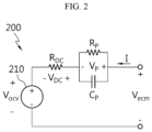
- FIG. 2 is a diagram showing the exemplary equivalent circuit model 200 of the battery B shown in FIG. 1
- FIG. 3 is a diagram exemplarily showing the SOC-OCV curve of the battery B shown in FIG. 1 .
- the equivalent circuit model 200 includes a voltage source 210, a resistor R DC and a RC pair R P , C P .
- the symbol I indicates the charge current.
- the output voltage V OCV of the voltage source 210 indicates the OCV of the battery B that was kept in the rest mode for a long time and reached an equilibrium.
- FIG. 3 shows two SOC-OCV curves 310, 320.
- the SOC-OCV curve 310 shows a change in OCV of the battery B during charge cycles
- the SOC-OCV curve 320 shows a change in OCV of the battery B during discharge cycles.
- the OCV in the SOC-OCV curve 310 is slightly higher than the OCV in the SOC-OCV curve 320, and this difference originates from hysteresis of the battery B during charge cycles and discharge cycles.
- the SOC-OCV curves 310, 320 shown in FIG. 3 are associated with a specific temperature or a specific temperature range, and other SOC-OCV curve associated with other temperature or temperature range may be additionally stored in the memory unit 140.
- both the two SOC-OCV curves 310, 320 have a voltage variation section, i.e., an SOC range in which a change (may be an absolute value) of OCV with respect to SOC is equal to or more than a reference value. That is, in FIG. 3 , the reference number 311 indicates the voltage variation section of the SOC-OCV curve 310, and the reference number 321 indicates the voltage variation section of the SOC-OCV curve 320.
- the resistor R DC is associated with an IR drop V DC of the battery B.
- the IR drop V DC is an instantaneous change in the terminal voltage across the battery B by the charge/discharge current.
- the memory unit 140 may record a first lookup table defining a correspondence between the SOC, the temperature and the resistor R DC , and the control unit 130 may determine the resistor R DC corresponding to the SOC and the temperature of the previous (or current) cycle from the first lookup table.
- the RC pair refers to a parallel circuit of the resistor R P and a capacitor C P , and is associated with the polarization voltage (also known as 'over potential') V P of the battery B.
- the time constant of the RC pair is the multiplication of the resistor R P and the capacitor C P .
- the memory unit 140 may record a second lookup table defining a correspondence between the SOC, the temperature and the RC pair R P , C P .
- the control unit 130 may determine the resistor R P and the capacitor C P corresponding to the SOC and the temperature of the previous (or current) cycle from the second lookup table. Determining the resistor R P and the capacitor C P may refer to determining the resistance of the resistor R P and the capacitance of the capacitor C P .
- Y ecm is a variable indicating the voltage across the equivalent circuit model 200, and may indicate the estimated terminal voltage of the battery B. As shown in the following Equation 2-1, Y ecm may be the sum of the output voltage V OCV , the IR drop Y DC and the polarization voltage V P .
- Equation 2-1 R DC [k] is the resistance of the resistor R DC in the current cycle, I[k] is the measured charge/discharge current in the current cycle, V OCV [k] is the estimated OCV in the current cycle, and V P [k] is the estimated polarization voltage in the current cycle.
- Equation 2-1 may be represented by the following Equation 2-2.
- C[k] is a system matrix having the two components c[k] and 1.
- c[k] is a conversion factor from SOC[k] to V OCV [k] by the function f OCV . That is, the multiplication of c[k] and SOC[k] is equal to [k].
- the polarization voltage V P may be calculated (estimated) using Equation 3-1 or Equation 3-2 below.
- V P k V P k ⁇ 1 ⁇ V P k ⁇ 1 ⁇ ⁇ t + I k C P ⁇ t
- V P k V P k ⁇ 1 e ⁇ ⁇ t ⁇ + R P k I k 1 ⁇ e ⁇ ⁇ t ⁇
- V P [k] denotes the polarization voltage in the current cycle
- V P [k-1] denotes the polarization voltage in the previous cycle
- ⁇ denotes the time constant of the RC pair R P , C P
- R P [k] denotes the resistance of the resistor R P in the current cycle.
- ⁇ may be the multiplication of one of R P [k-1] and R P [k] and one of C P [k-1] and C P [k].
- V P [0] may be set to 0 V.
- Equation 4-1 is associated with Equation 1 and Equation 3-1
- Equation 4-2 is associated with Equation 1 and Equation 3-2.
- Equation 4-1 and Equation 4-2 SOC-[k-1] denotes the estimated SOC in the previous cycle, V P ⁇ [k-1] denotes the estimated polarization voltage in the previous cycle, Q i denotes the maximum capacity of the battery B, and ⁇ denotes the time constant of the RC pair R P , C P .
- x ⁇ - [k] is a state matrix of the current cycle, and SOC ⁇ - [k] and V P ⁇ - [k] included therein are state variables indicating the estimated SOC and polarization voltage in the current cycle, respectively.
- Equation 5 is a time update equation of the first extended Kalman filter.
- Equation 5 P[k-1] denotes an estimated error covariance matrix in the previous cycle, W denotes a process noise covariance matrix, and P - [k] denotes an estimated error covariance matrix in the current cycle.
- a 1 is the Jacobian of the function f 1 in Equation 4-1 and Equation 4-2.
- the Jacobian A 1 may be represented by Equation 5-1 below.
- a 1 ⁇ ⁇ f 1 ⁇ x x x ⁇ ⁇ k
- a 1 T is a transposed matrix of A 1 .
- Equation 6 is a first measurement update equation of the first extended Kalman filter.
- K k P ⁇ k H 1 T H 1 P ⁇ k H 1 T + L ⁇ 1
- Equation 6 K[k] is the Kalman gain of the current cycle, H 1 is the Jacobian of the function h 1 according to the following Equation 6-1, H 1 T is a transposed matrix of H 1 , and L is a measurement noise covariance matrix.
- Equation 6 a terminal voltage estimation equation (an output equation) of Equation 6-1 below may be derived by associating the state matrix (x ⁇ - [k]) with Equation 2-1.
- Equation 6 The Jacobian H 1 in Equation 6 may be represented by Equation 6-2 below.
- H 1 ⁇ ⁇ h 1 ⁇ x x x ⁇ ⁇ k
- Equation 7 is a second measurement update equation of the first extended Kalman filter.
- Equation 7 P[k] is the result of correcting P - [k] from Equation 5 by Equation 7.
- Equation 8 is a third measurement update equation of the first extended Kalman filter.
- Equation 8 z[k] is the detected terminal voltage in the current cycle, z ⁇ [k] is the estimated terminal voltage in the current cycle, SOC ⁇ [k] is the estimated SOC in the current cycle (referred to as a 'first estimated SOC' in the claims), and V P ⁇ [k] is the estimated polarization voltage in the current cycle.
- x ⁇ [k] of Equation 8 may be used as x ⁇ [k-1] in Equation 4 in the next cycle.
- the first extended Kalman filter When the first extended Kalman filter is operated by the control unit 130, the first estimated SOC indicating the current SOC of the battery B according to the above-described process is outputted from the first extended Kalman filter.
- the control unit 130 may operate the second extended Kalman filter in parallel while the first extended Kalman filter is in operation. That is, the first extended Kalman filter and the second extended Kalman filter may be operated at the same time.
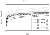
- FIG. 4 is a diagram used as a reference in describing the constant current charge/discharge map 400 according to the present disclosure.
- the constant current charge/discharge map 400 includes a plurality of charge curves 411 ⁇ 416 and a plurality of discharge curves 421 ⁇ 426.
- Each of the plurality of charge curves 411 ⁇ 416 indicates terminal voltage vs SOC of the battery B during constant current charge cycles using different current rates (also referred to as 'C-rate').
- CCV may be a term that describes the measured terminal voltage of the battery B during charging or discharging. During charge cycles, as the current rate is higher, the CCV at the same SOC is higher.
- Each of the plurality of discharge curves 421 ⁇ 416 indicates voltage (CCV) vs SOC of the battery B during constant current discharge cycles using different current rates. During discharge cycles, as the current rate is higher, the CCV at the same SOC is lower.
- the plurality of charge curves 411 ⁇ 416 and the plurality of discharge curves 421 ⁇ 416 include six charge curves and six discharge curves, respectively, and the current rate is 0.05 C, 0.15 C, 0.25 C, 0.50 C, 1.00 C and 1.50 C in an ascending order.
- Each curve included in the constant current charge/discharge map 400 may be stored in the memory unit 140 in the form of a function.
- FIG. 4 shows the plurality of charge curves 411 ⁇ 416 and the plurality of discharge curves 421 ⁇ 416 as well as the two SOC-OCV curves 310, 320 of FIG. 3 .
- the voltage variation section present in the SOC-OCV curve 310 disappears gradually.
- the voltage variation section present in the SOC-OCV curve 320 also disappears gradually.
- the equivalent circuit model 200 it is not easy to design the equivalent circuit model 200 to accurately describe so-called fading, i.e., a phenomenon in which the voltage variation section disappears as the current rate increases. Additionally, when the equivalent circuit model 200 that does not accurately describe the fading characteristics at or above a predetermined level is used to estimate the SOC of the battery B during constant current charging or constant current discharging, there may be a big difference between the actual SOC and the estimated SOC.
- the SOC of the battery B may be estimated based on the output value of the second extended Kalman filter using the constant current charge/discharge map 400 rather than the output value of the first extended Kalman filter, or the SOC of the battery B may be estimated by combining (for example, a weighted average) the output value of the first extended Kalman filter with the output value from the second extended Kalman filter.
- the second extended Kalman filter only uses SOC as its state variable, and may be represented by Equation 9 below.
- Equation 9 x ⁇ [k-1] is the estimated SOC in the previous cycle, i[k] is the current value of the charge/discharge current detected in the current cycle, Q i is the maximum capacity of the battery B, and x ⁇ - [k] is the estimated SOC in the current cycle.
- x ⁇ - [k] may be equal to SOC ⁇ - [k] indicating the estimated SOC in the current cycle, and f 2 (x ⁇ [k-1]) may be equal to x ⁇ [k-1].
- Equation 10 is a time update equation of the second extended Kalman filter.
- P ⁇ k A 2 P k ⁇ 1 A 2 T + w
- Equation 10 P[k-1] denotes the estimated error covariance in the previous cycle, w denotes the process noise covariance, and P - [k] denotes the estimated error covariance in the current cycle.
- a 2 is the Jacobian of the function f 2 of Equation 9.
- the Jacobian A 2 may be represented by Equation 10-1 below.
- a 2 ⁇ ⁇ f 2 ⁇ x x x ⁇ ⁇ k
- a 2 T is a transposed matrix of A 2 .
- the control unit 130 performs a measurement update process when the time update process using Equation 9 and Equation 10 is completed.
- Equation 11 is a first measurement update equation of the second extended Kalman filter.
- H k P ⁇ k H 2 T H 2 P ⁇ k H 2 T + l ⁇ 1
- Equation 11 K[k] is the Kalman gain in the current cycle
- H 2 is the Jacobian of the function h 2 in the following Equation 11-1
- H 2 T is a transposed matrix of H 2
- l is a measurement noise covariance.
- Equation 12 a terminal voltage estimation equation (an output equation) of Equation 12-1 below may be derived.
- the function f CCV_I[k] is a function that defines any one charge or discharge curve associated with the current rate corresponding to I[k] among the curves included in the constant current charge/discharge map 400.
- the control unit 130 selects any one charge curve corresponding to I[k] from the plurality of charge curves 411 ⁇ 416 in response to I[k] being the charge current. Selecting any one charge curve may refer to acquiring the function f CCV_I[k] from the memory unit 140.
- control unit 130 may set the estimated terminal voltage of the battery B in the current cycle so that the state variable (SOC ⁇ - [k]) is equal to the output value (z ⁇ [k]) of the function f CCV_I[k] at the time of input.
- Equation 12-1 the Jacobian H in Equation 12-1 may be represented by the following Equation 12-2.
- H 2 ⁇ ⁇ h 2 ⁇ x x x ⁇ ⁇ k
- Equation 13 is a second measurement update equation of the second extended Kalman filter.
- Equation 13 P[k] is the result of correcting P - [k] from Equation 10 by Equation 13.
- Equation 14 is a third measurement update equation of the second extended Kalman filter.
- Equation 14 z[k] is the detected terminal voltage in the current cycle, z ⁇ [k] is the estimated terminal voltage in the current cycle, and SOC ⁇ [k] is the estimated SOC in the current cycle (referred to as a 'second estimated SOC' in the claims).
- x ⁇ [k] by Equation 14 may be used as x ⁇ [k-1] in Equation 9 in the next cycle.
- the control unit 130 may determine the maximum capacity Q i of the battery B that is the basic variable used by the first extended Kalman filter and the second extended Kalman filter by using Equation 15 below.
- ⁇ SOC is a change in SOC for the capacity update period
- ⁇ Q is the accumulated value of the current by ampere counting for the capacity update period
- 'a' is a time index corresponding to the start time of the capacity update period
- 'b' is a time index corresponding to the end time of the capacity update period.
- the capacity update period may be may be the latest period during which ⁇ SOC is equal to or higher than a threshold change (for example, 0.5).
- the maximum capacity gradually reduces. Accordingly, when the degree of degradation of the battery B is above a predetermined level, the battery cell is highly likely to suddenly become inoperable, and accordingly it is necessary to estimate the SOC more precisely.
- FIG. 5 is a flowchart exemplarily showing a battery management method for SOC estimation method according to a first embodiment of the present disclosure.
- the method of FIG. 5 may be repeatedly performed at a preset time interval from the time at which a predetermined event occurs.
- step S510 the control unit 130 detects the terminal voltage V[k] and the charge/discharge current I[k] of the battery B, and determines the voltage value V[k] of the terminal voltage and the current value I[k] of the charge/discharge current.
- the control unit 130 determines the first estimated SOC by inputting the voltage value V[k], the current value I[k] and the estimated SOC in the previous cycle to the first extended Kalman filter.
- the first extended Kalman filter is an SOC estimation logic using the equivalent circuit model 200 and the SOC-OCV curve 300 of the battery B.
- the first estimated SOC may be a candidate value indicating the SOC of the battery B in the current cycle.
- the voltage value V[k] of the terminal voltage may be used as z[k] in Equation 8.
- the control unit 130 may provide the first extended Kalman filter with the SOC-OCV curve 310 among the two SOC-OCV curves 310, 320.
- the control unit 130 may provide the first extended Kalman filter with the SOC-OCV curve 320 among the two SOC-OCV curves 310, 320.
- step S530 the control unit 130 determines the second estimated SOC by inputting the current value and the estimated SOC in the previous cycle to the second extended Kalman filter.
- the second extended Kalman filter is an SOC estimation logic using the constant current charge/discharge map 400 of the battery B.
- the second estimated SOC may be another candidate value indicating the SOC of the battery B in the current cycle.
- the control unit 130 may provide the second extended Kalman filter with any one charge curve associated with the current rate corresponding to the current value I[k] among the plurality of charge curves 411 ⁇ 416.
- control unit 130 may provide the second extended Kalman filter with any one discharge curve associated with the current rate corresponding to the current value I[k] among the plurality of discharge curves 421 ⁇ 426.
- the average of two SOCs corresponding to the OCV at the initial time point t 0 in the two curves 310, 320 may be inputted to the first extended Kalman filter and the second extended Kalman filter as the estimated SOC in the previous cycle in the step S520 and the step S530.
- step S540 the control unit 130 determines the SOC of the battery B in the current cycle based on at least one of the first estimated SOC or the second estimated SOC.
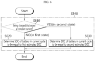
- FIG. 6 is a flowchart exemplarily showing a battery management method for SOC estimation according to a second embodiment of the present disclosure.
- the method of FIG. 6 may be an example of a set of subroutines of the step S540 of the battery management method according to FIG. 5 .
- step S610 the control unit 130 determines whether the battery B is being charged/discharged at a constant current based on the current value I[k] or current time-series data indicating a time-dependent change history of the charge/discharge current.
- the current time-series data includes I[1] ⁇ I[100] as data points.
- a value of the step S610 being "NO” indicates a first state in which the battery B is not being charged/discharged at a constant current.
- the process moves to step S620.
- the value of the step S610 being "YES” indicates a second state in which the battery B is being charged/discharged at a constant current.
- the process moves to step S630.
- control unit 130 determines the SOC of the battery B in the current cycle to be equal to the first estimated SOC.
- control unit 130 determines the SOC of the battery B in the current cycle to be equal to the second estimated SOC.
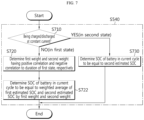
- FIG. 7 is a flowchart exemplarily showing a battery management method for SOC estimation according to a third embodiment of the present disclosure
- FIG. 8 is a diagram used as a reference in describing the method according to FIG. 7 .
- the method of FIG. 7 may be another example of the set of subroutines of the step S540 of the battery management method according to FIG. 5 . That is, the third embodiment is a variation of the second embodiment.
- step S710 the control unit 130 determines whether the battery B is being charged/discharged at a constant current based on the current value I[k] or the current time-series data indicating the time-dependent change history of the charge/discharge current.
- a value of the step S710 is "NO”
- the process moves to step S720.
- the value of the step S710 is "YES”
- the process moves to step S730.
- the control unit 130 determines a first weight and a second weight having a positive correlation and a negative correlation to the duration of the first state, respectively.
- the first weight may be larger than the second weight.
- the sum of the first weight and the second weight may be a preset constant (for example, 1). In this case, when any one of the first weight and the second weight is determined, the remaining one may be also determined.
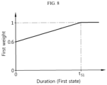
- FIG. 8 is a graph exemplarily showing a change in the first weight as a function of the duration of the first state. Referring to FIG. 8 , it shows that the minimum value of the first weight is 0.6, in the time range 0 ⁇ t S1 , as the duration of the first state increases, the first weight increases, and from the time when the duration of the first state reaches a first reference time t S1 , the first weight is constantly maintained at 1.
- step S722 the control unit 130 determines the SOC of the battery B in the current cycle to be equal to the weighted average of the first estimated SOC and the second estimated SOC by the first weight and the second weight.
- the first weight 0.8
- the first estimated SOC 0.60
- the second estimated SOC 0.62
- step S730 the control unit 130 determines the SOC of the battery B in the current cycle to be equal to the second estimated SOC.
- FIG. 9 is a flowchart exemplarily showing a battery management method for SOC estimation according to a fourth embodiment of the present disclosure
- FIG. 10 is a diagram used as a reference in describing the method according to FIG. 9 .
- the method of FIG.9 may be another example of the set of subroutines of the step S540 of the battery management method according to FIG. 5 . That is, the fourth embodiment is an additional variation of the second embodiment.
- step S910 the control unit 130 determines whether the battery B is being charged/discharged at a constant current based on the current value or the current time-series data indicating the time-dependent change history of the charge/discharge current.
- a value of the step S910 is "NO”
- the process moves to step S920.
- the value of the step S910 is "YES”
- the process moves to step S930.
- control unit 130 determines the SOC of the battery B in the current cycle to be equal to the first estimated SOC.
- the control unit 130 determines a third weight and a fourth weight having a negative correlation and a positive correlation to the duration of the second state, respectively.
- the third weight may be smaller than the fourth weight.
- the sum of the third weight and the fourth weight may be a preset constant (for example, 1). In this case, when any one of the third weight and the fourth weight is determined, the remaining one may be also determined.
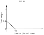
- FIG. 10 is a graph exemplarily showing a change in the third weight as a function of the duration of the second state. Referring to FIG. 10 , it shows that the maximum value of the third weight is 0.4, in the time range (0 ⁇ t S2 ), as the duration of the second state increases, the third weight decreases, and from the time when the duration of the second state reaches a second reference time t S2 , the third weight is constantly maintained at 0.
- step S932 the control unit 130 determines the SOC of the battery B in the current cycle to be equal to the weighted average of the first estimated SOC and the second estimated SOC by the third weight and the fourth weight.
- the third weight 0.1
- the first estimated SOC 0.60
- the second estimated SOC 0.62
- FIG. 9 is a flowchart exemplarily showing a battery management method for SOC estimation according to a fifth embodiment of the present disclosure.
- the method of FIG. 11 may be another example of the set of subroutines of the step S540 of the battery management method according to FIG. 5 . That is, the fifth embodiment is an additional variation of the second embodiment.
- step S1110 the control unit 130 determines whether the battery B is being charged/discharged at a constant current based the current value or on the current time-series data indicating the time-dependent change history of the charge/discharge current.
- a value of the step S1110 is "NO”
- the process moves to step S1120.
- the value of the step S1110 is "YES”
- the process moves to step S1130.
- control unit 130 determines the first weight and the second weight having a positive correlation and a negative correlation to the duration of the first state, respectively.
- step S1122 the control unit 130 determines the SOC of the battery B in the current cycle to be equal to the weighted average of the first estimated SOC and the second estimated SOC by the first weight and the second weight.
- step S1120 and the step S1122 are the same as the step S720 and the step S722 of FIG. 7 .
- control unit 130 determines the third weight and the fourth weight having a negative correlation and a positive correlation to the duration of the second state, respectively.
- step S1132 the control unit 130 determines the SOC of the battery B in the current cycle to be equal to the weighted average of the first estimated SOC and the second estimated SOC by the third weight and the fourth weight.
- step S1130 and the step S1132 are the same as the step S930 and the step S932 of FIG. 9 .
- FIG. 12 is a flowchart exemplarily showing a method for determining whether the battery is being charged/discharged at a constant current.
- the method of FIG. 12 may be the set of subroutines of at least one of the step S610 of FIG. 6 , the step S710 of FIG. 7 , the step S910 of FIG. 9 or the step S1110 of FIG. 11 .
- the control unit 130 filters the current time-series data using a High Pass Filter (HPF).
- HPF High Pass Filter
- the high pass filter is a filter that removes a signal component that is smaller than a predetermined cutoff frequency, and allows a signal component that is larger than the cutoff frequency to pass therethrough.
- the output value of the high path filter may be 0, and in other states, the output value of the high pass filter may not be 0. As fluctuations of the current flowing in the battery B are smaller, the output value of the high pass filter is closer to 0.
- step S1220 the control unit 130 determines whether the output value of the high pass filter lies in a reference range (for example, -0.001 to 0.001).
- a value of the step S1220 is "YES”
- the process may move to step S1230.
- the reference range may be properly preset in view of the filtering precision of the high pass filter and the detection precision of the current detection unit 113.
- the value of the step S1220 is "NO"
- the process moves to any one of the step S620 of FIG. 6 , the step S720 of FIG. 7 , the step S910 of FIG. 9 and the step S1120 of FIG. 11 .
- the control unit 130 determines whether or not the current value is 0 [A].
- a value of the step S1230 is "YES”
- the process moves to any one of the step S620 of FIG. 6 , the step S720 of FIG. 7 , the step S910 of FIG. 9 and the step S1120 of FIG. 11 .
- the value of the step S1230 is "NO”
- the process moves to any one of the step S630 of FIG. 6 , the step S730 of FIG. 7 , the step S930 of FIG. 9 or the step S1130 of FIG. 11 .
- step S610 of FIG. 6 the step S710 of FIG. 7 , the step S910 of FIG. 9 and the step S1110 of FIG. 11 have been described as the subroutines of the step S540, it should be understood as an example.
- at least one of the step S610 of FIG. 6 , the step S710 of FIG. 7 , the step S910 of FIG. 9 or the step S1110 of FIG. 11 may be performed using the current value determined in the step S510 before the step S520 or step S530 of FIG. 5 is performed.
Landscapes
- Engineering & Computer Science (AREA)
- General Physics & Mathematics (AREA)
- Physics & Mathematics (AREA)
- Power Engineering (AREA)
- Mechanical Engineering (AREA)
- Transportation (AREA)
- Sustainable Development (AREA)
- Sustainable Energy (AREA)
- Life Sciences & Earth Sciences (AREA)
- Manufacturing & Machinery (AREA)
- Chemical & Material Sciences (AREA)
- Chemical Kinetics & Catalysis (AREA)
- Electrochemistry (AREA)
- General Chemical & Material Sciences (AREA)
- Microelectronics & Electronic Packaging (AREA)
- Secondary Cells (AREA)
- Tests Of Electric Status Of Batteries (AREA)
- Charge And Discharge Circuits For Batteries Or The Like (AREA)
Abstract
Description
- The present disclosure relates to State Of Charge estimation in a battery.
- The present application claims priority to
Korean Patent Application No. 10-2023-0082153 filed in the Republic of Korea on June 26, 2023 - Recently, there has been a dramatic increase in demand for portable electronic products such as laptop computers, video cameras and mobile phones, and with the extensive development of electric vehicles, accumulators for energy storage, robots and satellites, many studies are being made on high performance batteries that can be recharged repeatedly.
- Currently, commercially available batteries include nickel-cadmium batteries, nickel-hydrogen batteries, nickel-zinc batteries, lithium batteries and the like, and among them, lithium batteries have little or no memory effect, and thus they are gaining more attention than nickel-based batteries for their advantages that recharging can be done whenever it is convenient, the self-discharge rate is very low and the energy density is high.
- One of the important parameters required to control the charge and discharge of a battery is a state of charge (SOC). The SOC is a parameter indicating a relative ratio of the current capacity to the maximum capacity indicating the total electrical energy when the battery is fully charged, and may be represented as 0 to 1 (or 0% to 100%). For example, when the maximum capacity of the battery is 1000 Ah (ampere-hour), and the capacity currently stored in the battery is 750 Ah, the SOC of the battery is 0.75 (or 75%).
- To estimate the SOC of the battery, the extended Kalman filter (EKF) is widely used.
- The extended Kalman filter is an SOC estimation logic using an equivalent circuit model (ECM) and an SOC-Open Circuit Voltage (OCV) curve, each prepared beforehand according to electrical and chemical properties of the battery, and outputs an estimated SOC that is one of state variables when inputting a voltage and a current of the battery as input variables.
- Meanwhile, some types of batteries such as lithium iron phosphate (LFP) batteries have a voltage variation section in the SOC-OCV curve. An SOC-Closed Circuit Voltage (CCV) curve obtained by repeatedly measuring a terminal voltage of the battery in a constant current charge mode and/or a constant current discharge mode has a more indistinct voltage variation section than the SOC-OCV curve. As the current rate is higher, the voltage variation section fades away or disappears completely.
- To fully reflect the characteristics of the voltage variation section of the battery on the EKF, it is necessary to precisely design the ECM. However, as the design precision of the ECM increases, the number of devices included in the ECM increases so much, and a connection relationship between the devices becomes complex, resulting in increased complexity and data storage space required for SOC estimation. Additionally, despite high design precision of the ECM, it is difficult to fully reflect the voltage variation section that changes depending on the current rate.
- To solve the problem caused by the ECM constraints, an approach to estimate the SOC of the battery in a constant current charge/discharge mode using ampere counting rather than EKF may be contemplated. The ampere counting refers to the technique that estimates the SOC of the battery by converting an accumulated value of the current flowing through the battery to a change in SOC. However, when the constant current charge/discharge mode lasts for a long time, a current measurement error also accumulates over time, resulting in low accuracy in SOC estimation by ampere counting.
- The present disclosure is designed to solve the above-described problem, and therefore the present disclosure is directed to a battery pack for estimating a state of charge of a battery having a characteristic that a voltage variation section changes depending on a current rate by using two extended Kalman filters having a complementary relationship in parallel, an electric vehicle including the battery pack and a battery management method.
- These and other objectives and advantages of the present disclosure may be understood by the following description and will be apparent from the embodiments of the present disclosure. In addition, it will be easily understood that the objectives and advantages of the present disclosure may be realized by the means set forth in the appended claims and a combination thereof.
- A battery management system according to an aspect of the present disclosure is for a battery having a characteristic that a voltage variation section changes depending on a current rate. The battery management system includes a sensing unit configured to detect a terminal voltage and a charge/discharge current of the battery, a memory unit configured to store a first Kalman filter which is a state of charge (SOC) estimation logic using an equivalent circuit model and an SOC-open circuit voltage (OCV) curve of the battery and a second Kalman filter which is an SOC estimation logic using a constant current charge/discharge map of the battery, and a control unit configured to determine a voltage value of the detected terminal voltage and a current value of the detected charge/discharge current. The control unit is configured to determine a first estimated SOC by inputting the voltage value, the current value and an estimated SOC in a previous cycle to the first Kalman filter, and determine a second estimated SOC by inputting the current value and the estimated SOC in the previous cycle to the second Kalman filter. The control unit is configured to determine an SOC of the battery in a current cycle based on at least one of the first estimated SOC or the second estimated SOC.
- The control unit may be configured to determine whether the battery is in a first state in which the battery is not being charged/discharged at a constant current or a second state in which the battery is being charged/discharged at the constant current based on the current value or current time-series data indicating a time-dependent change history of the charge/discharge current. The control unit may be configured to determine the SOC of the battery in the current cycle to be equal to the first estimated SOC in response to the determination that the battery is in the first state. The control unit may be configured to determine the SOC of the battery in the current cycle to be equal to the second estimated SOC in response to the determination that the battery is in the second state.
- The control unit may be configured to determine whether the battery is in a first state in which the battery is not being charged/discharged at a constant current or a second state in which the battery is being charged/discharged at the constant current based on the current value or current time-series data indicating a time-dependent change history of the charge/discharge current. The control unit may be configured to determine a first weight having a positive correlation to a duration of the first state and a second weight having a negative correlation to the duration of the first state in response to the determination that the battery is in the first state. The control unit may be configured to determine the SOC of the battery in the current cycle to be equal to a weighted average of the first estimated SOC and the second estimated SOC by the first weight and the second weight.
- The first weight may be larger than the second weight. A sum of the first weight and the second weight may be 1.
- The control unit may be configured to determine whether the battery is in a first state in which the battery is not being charged/discharged at a constant current or a second state in which the battery is being charged/discharged at the constant current based on the current value or current time-series data indicating a time-dependent change history of the charge/discharge current. The control unit may be configured to determine a third weight having a negative correlation to a duration of the second state and a fourth weight having a positive correlation to the duration of the second state in response to the determination that the battery is in the second state. The control unit may be configured to determine a weight average of the first estimated SOC and the second estimated SOC by the third weight and the fourth weight as the SOC of the battery in the current cycle.
- The third weight may be smaller than the fourth weight. A sum of the third weight and the fourth weight may be 1.
- The constant current charge/discharge map may include a plurality of charge curves indicating a relationship between the SOC and the voltage of the battery during constant current charging using a plurality of current rates, and a plurality of discharge curves indicating a relationship between the SOC and the voltage of the battery during constant current discharging using the plurality of current rates.
- The second estimated SOC may be outputted from the second Kalman filter in response to any one curve of the plurality of charge curves and the plurality of discharge curves being provided to the second Kalman filter.
- The control unit may be configured to provide the second Kalman filter with any one charge curve associated with the current rate corresponding to the current value among the plurality of charge curves in response to the battery being charged at the constant current. The control unit may be configured to provide the second Kalman filter with any one discharge curve associated with the current rate corresponding to the current value among the plurality of discharge curves in response to the battery being discharged at the constant current.
- A battery pack according to another aspect of the present disclosure includes the battery management system.
- An electric vehicle according to still another aspect of the present disclosure includes the battery pack.
- A battery management method according to yet another aspect of the present disclosure is for a battery having a characteristic that a voltage variation section changes depending on a current rate. The battery management method includes detecting a terminal voltage and a charge/discharge current of the battery, determining a voltage value of the detected terminal voltage and a current value of the detected charge/discharge current, determining a first estimated SOC by inputting the voltage value, the current value and an estimated SOC in a previous cycle to a first Kalman filter which is an SOC estimation logic using an equivalent circuit model and an SOC-OCV curve of the battery, determining a second estimated SOC by inputting the current value and the estimated SOC in the previous cycle to a second Kalman filter which is an SOC estimation logic using a constant current charge/discharge map of the battery, and determining an SOC of the battery in a current cycle based on at least one of the first estimated SOC or the second estimated SOC.
- The determining of the SOC of the battery in the current cycle may include determining whether the battery is in a first state in which the battery is not being charged/discharged at a constant current or a second state in which the battery is being charged/discharged at the constant current based on the current value or current time-series data indicating a time-dependent change history of the charge/discharge current, determining the first estimated SOC as the SOC of the battery in the current cycle in response to the determination that the battery is in the first state, and determining the second estimated SOC as the SOC of the battery in the current cycle in response to the determination that the battery is in the second state.
- The determining of the SOC of the battery in the current cycle may include determining whether the battery is in a first state in which the battery is not being charged/discharged at a constant current or a second state in which the battery is being charged/discharged at the constant current based on the current value or current time-series data indicating a time-dependent change history of the charge/discharge current, determining a first weight having a positive correlation to a duration of the first state and a second weight having a negative correlation to the duration of the first state in response to the determination that the battery is in the first state, and determining a weighted average of the first estimated SOC and the second estimated SOC by the first weight and the second weight as the SOC of the battery in the current cycle.
- The determining of the SOC of the battery in the current cycle may include determining whether the battery is in a first state in which the battery is not being charged/discharged at a constant current or a second state in which the battery is being charged/discharged at the constant current based on the current value or current time-series data indicating a time-dependent change history of the charge/discharge current, determining a third weight having a negative correlation to a duration of the second state and a fourth weight having a positive correlation to the duration of the second state in response to the determination that the battery is in the second state, and determining a weighted average of the first estimated SOC and the second estimated SOC by the third weight and the fourth weight as the SOC of the battery in the current cycle.
- The constant current charge/discharge map may include a plurality of charge curves indicating a relationship between the SOC and the voltage of the battery during constant current charging using a plurality of current rates, and a plurality of discharge curves indicating a relationship between the SOC and the voltage of the battery during constant current discharging using the plurality of current rates.
- The second estimated SOC may be outputted from the second Kalman filter in response to any one curve of the plurality of charge curves and the plurality of discharge curves being provided to the second Kalman filter.
- According to at least one of the embodiments of the present disclosure, two extended Kalman filters having a complementary relationship are used in parallel to estimate the SOC of the battery having a characteristic that the voltage variation section changes depending on the current rate, in order to reduce the SOC estimation error with change in charge/discharge mode of the battery, compared to a single extended Kalman filter, thereby improving SOC estimation accuracy.
- The effects of the present disclosure are not limited to the above-mentioned effects, and these and other effects will be clearly understood by those skilled in the art from the appended claims.
- The accompanying drawings illustrate exemplary embodiment of the present disclosure, and together with the following detailed description, serve to provide a further understanding of the technical aspect of the present disclosure, and thus the present disclosure should not be construed as being limited to the drawings.
-
FIG. 1 is a diagram exemplarily showing a configuration of an electric vehicle according to the present disclosure. -
FIG. 2 is a diagram showing an exemplary equivalent circuit model of a battery shown inFIG. 1 . -
FIG. 3 is a diagram exemplarily showing a State of Charge (SOC)-Open Circuit Voltage (OCV) curve of a battery shown inFIG. 1 . -
FIG. 4 is a diagram used as a reference in describing a constant current charge/discharge map according to the present disclosure. -
FIG. 5 is a flowchart exemplarily showing a battery management method for SOC estimation according to a first embodiment of the present disclosure. -
FIG. 6 is a flowchart exemplarily showing a battery management method for SOC estimation according to a second embodiment of the present disclosure. -
FIG. 7 is a flowchart exemplarily showing a battery management method for SOC estimation according to a third embodiment of the present disclosure. -
FIG. 8 is a diagram used as a reference in describing the method according toFIG. 7 . -
FIG. 9 is a flowchart exemplarily showing a battery management method for SOC estimation according to a fourth embodiment of the present disclosure. -
FIG. 10 is a diagram used as a reference in describing the method according toFIG. 9 . -
FIG. 11 is a flowchart exemplarily showing a battery management method for SOC estimation according to a fifth embodiment of the present disclosure. -
FIG. 12 is a flowchart exemplarily showing a method for determining whether a battery is being charged/discharged at a constant current. - Hereinafter, exemplary embodiments of the present disclosure will be described in detail with reference to the accompanying drawings. Prior to the description, it should be understood that the terms or words used in the specification and the appended claims should not be construed as being limited to general and dictionary meanings, but rather interpreted based on the meanings and concepts corresponding to the technical aspect of the present disclosure on the basis of the principle that the inventor is allowed to define the terms appropriately for the best explanation.
- Therefore, the embodiments described herein and illustrations shown in the drawings are provided to describe the exemplary embodiments of the present disclosure by way of example, but not intended to fully describe the technical aspect of the present disclosure, so it should be understood that a variety of other equivalents and modifications could have been made thereto at the time the application was filed.
- The terms including the ordinal number such as "first", "second" and the like, are used to distinguish one element from another among various elements, but not intended to limit the elements by the terms.
- Unless the context clearly indicates otherwise, it will be understood that the term "comprises" when used in this specification, specifies the presence of stated elements, but does not preclude the presence or addition of one or more other elements. Additionally, the term "control unit" as used herein refers to a processing unit of at least one function or operation, and may be implemented by hardware or software alone or in combination.
- In addition, throughout the specification, it will be further understood that when an element is referred to as being "connected to" another element, it can be directly connected to the other element or intervening elements may be present.
-
FIG. 1 is a diagram exemplarily showing a configuration of an electric vehicle according to the present disclosure. - The
electric vehicle 1 includes avehicle controller 2, abattery pack 10, arelay 20, aninverter 30 and anelectric motor 40. Charge/discharge terminal P+, P- of thebattery pack 10 may be electrically coupled to acharger 3 through a charge cable. Thecharger 3 may be included in theelectric vehicle 1 or may be present at a charging station. - The vehicle controller 2 (for example, an Electronic Control Unit (ECU)) is configured to transmit a key-on signal to a
battery management system 100 when a user switches a starter button (not shown) of theelectric vehicle 1 to an ON-position. Thevehicle controller 2 is configured to transmit a key-off signal to thebattery management system 100 when the user switches the starter button to an OFF-position. Thecharger 3 may provide the charge power of constant current or constant voltage through the charge/discharge terminal P+, P- of thebattery pack 10 via communication with thevehicle controller 2. - The
battery pack 10 includes a battery module 11 and thebattery management system 100. - The battery module 11 includes at least one battery B. The battery B can be recharged repeatedly. Additionally, the battery B is not limited to a particular type and may include any battery having a characteristic that a voltage variation section changes depending on a current rate like lithium iron phosphate (LFP) batteries.
- When the battery module 11 includes a plurality of batteries, the plurality of batteries may be connected in series, in parallel, or in series and in parallel.
- The
relay 20 is electrically connected in series to the battery module 11 through a power path connecting the battery module 11 to theinverter 30.FIG. 1 shows therelay 20 connected between a positive terminal of the battery module 11 and the charge/discharge terminal P+. Therelay 20 is controlled to turn on/off in response to the switching signal from thebattery management system 100. Therelay 20 may be a mechanical contactor that turns on or off by the magnetic force of a coil or a semiconductor switch such as Metal Oxide Semiconductor Field Effect transistor (MOSFET). - The
inverter 30 is configured to convert the direct current from the battery module 11 to alternating current in response to a command from thebattery management system 100 or thevehicle controller 2. - The
electric motor 40 operates using the alternating current from theinverter 30. Theelectric motor 40 may include, for example, a 3-phase alternatingcurrent motor 40. - The
battery management system 100 includes avoltage detection unit 111, acurrent detection unit 113, a temperature detection unit 115 and acontrol unit 130. Thebattery management system 100 may further include acommunication circuit 150. - The
voltage detection unit 111 is connected to the positive and negative terminals of the battery B included in the battery module 11, and is configured to detect a terminal voltage across two terminals of the battery B, and output a voltage signal SV indicating the detected terminal voltage to thecontrol unit 130. - The
current detection unit 113 is connected in series to the battery module 11 through a current path between the battery module 11 and theinverter 30. Thecurrent detection unit 113 is configured to detect a charge/discharge current flowing through the battery module 11, and output a current signal SI indicating the detected charge/discharge current to thecontrol unit 130. Thecurrent detection unit 113 may include one of known current detection devices such as, for example, a shunt resistor or a Hall-effect device or a combination thereof. - The temperature detection unit 115 is configured to detect a temperature of the battery B, and output a temperature signal ST indicating the detected temperature to the
control unit 130. The temperature detection unit 115 may include one of known temperature detection devices such as, for example, a thermocouple, a thermistor or a bimetal, or a combination thereof. - The
voltage detection unit 111, thecurrent detection unit 113 and the temperature detection unit 115 may be referred to as a 'sensing unit'. - The
communication circuit 150 is configured to support wired or wireless communication between thecontrol unit 130 and thevehicle controller 2. The wired communication may be, for example, controller area network (CAN) communication, and the wireless communication may be, for example, Zigbee or Bluetooth communication. The communication protocol is not limited to a particular type and may include those that support the wired/wireless communication between thecontrol unit 130 and thevehicle controller 2. Thecommunication circuit 150 may include an output device (for example, a display, a speaker) to provide information received from thecontrol unit 130 and/or thevehicle controller 2 into a recognizable format for the user. - The
control unit 130 is operably coupled to therelay 20, thevoltage detection unit 111, thecurrent detection unit 113, the temperature detection unit 115 and thecommunication circuit 150. The operably coupled refers to direct/indirect connection to enable signal transmission and reception in one or two directions. - The
control unit 130 may collect the voltage signal SV from thevoltage detection unit 111, the current signal SI from thecurrent detection unit 113 and/or the temperature signal ST from the temperature detection unit 115. Thecontrol unit 130 may convert and record each of the analog signals collected from thedetection units control unit 130. - The
control unit 130 may be referred to as a 'control circuit' or a 'battery controller', and may be implemented in hardware using at least one of application specific integrated circuits (ASICs), digital signal processors (DSPs), digital signal processing devices (DSPDs), programmable logic devices (PLDs), field programmable gate arrays (FPGAs), microprocessors or electrical units for performing other functions. - A
memory unit 140 may include, for example, at least type of storage medium of flash memory type, hard disk type, Solid State Disk (SSD) type, Silicon Disk Drive (SDD) type, multimedia card micro type, random access memory (RAM), static random access memory (SRAM), read-only memory (ROM), electrically erasable programmable read-only memory (EEPROM) or programmable read-only memory (PROM). Thememory unit 140 may store data and programs required for the computation operation by thecontrol unit 130. Thememory unit 140 may store data indicating the results of the computation operation by thecontrol unit 130. AlthoughFIG. 1 shows that thememory unit 140 is physically independent from thecontrol unit 130, thememory unit 140 may be included in thecontrol unit 130. - The
memory unit 140 may store an equivalent circuit model (seeFIG. 2 ), a State of Charge (SOC)-Open Circuit Voltage (OCV) curve (seeFIG. 3 ), a constant current charge/discharge map (seeFIG. 4 ), a first extended Kalman filter and a second extended Kalman filter. Each of the SOC-OCV curve, the constant current charge/discharge map, the first extended Kalman filter and the second extended Kalman filter will be described in more detail below. - The
control unit 130 may turn on therelay 20 in response to the key-on signal. Thecontrol unit 130 may turn off therelay 20 in response to the key-off signal. The key-off signal indicates a switch from a cycle mode to a rest mode. Alternatively, thevehicle controller 2 may take responsibility for the on/off control of therelay 20, instead of thecontrol unit 130. - While the
relay 20 is turned on, the battery B of the battery module 11 enters the cycle mode. The cycle mode refers to an operational state in which the battery can be charged and discharged. The cycle mode may include a constant current charge mode, a constant current discharge mode and a non-constant current charge/discharge mode. - The constant current charge mode refers to a state in which a charge current of constant current rate flows in the battery B. The constant current discharge mode refers to a state in which a discharge current of constant current rate flows in the battery B. The non-constant current charge/discharge mode refers to a state in which a non-constant charge or discharge current flows in the battery B.
- While the
relay 20 is turned off, the battery B of the battery module 11 enters the rest mode. The rest mode refers to an operational state in which the charge/discharge current is interrupted and the battery cannot be charged and discharged. - In the specification, the battery B in a first operational state refers to the battery B in the rest mode or the non-constant current charge/discharge mode. The battery B in a second operational state refers to the battery B in the constant current charge mode or the constant current discharge mode.
- While the battery module 11 is in the cycle mode, the
control unit 130 may determine a voltage value, a current value and a temperature value based on the voltage signal SV, the current signal SI and the temperature signal ST, respectively, and determine (estimate) the SOC of the battery B based on the voltage value, the current value and/or the temperature value. The SOC refers to a ratio of the remaining capacity to the full charge capacity (the maximum capacity) of the battery B. - In the specification, SOC is indicated as a range between 0 and 1,
SOC 0 refers to fully discharged state andSOC 1 refers to fully charged state. - In the specification, it is assumed that when U is a certain variable, 'U[k-1]' denotes a value of U in the previous cycle, and 'U[k]' denotes a value of U in the current cycle. The symbol k used together with the symbol [] is a time index that increases by 1 each time a predetermined period of time Δt (for example, 0.001 sec) has elapsed from the initial time point t0.
- At the initial time point t0, k=0 may be set. For example, k = 10 indicates that Δt × 10 has elapsed from the initial time point t0 and the estimated SOC was calculated 10 times during the period of time. The initial time point t0 is a time point at which a predetermined event occurs, for example, an event of a switch of the
control unit 130 from a sleep state to a wakeup state. Thecontrol unit 130 may be switched from the sleep state to the wakeup state in response to the key-on of theelectric vehicle 1, and from the wakeup state to the sleep state in response to the key-off of theelectric vehicle 1. - Hereinafter, the equivalent circuit model and the SOC-OCV curve used by the first extended Kalman filter will be described. The following
Equation 1 to Equation 8 expresses the first extended Kalman filter, and in describing each ofEquation 1 to Equation 8, the already described variables may be omitted to avoid redundancy. - The first extended Kalman filter uses a state equation (see the following Equation 4-1 and Equation 4-2) including SOC and polarization voltage as state variables, and the following
Equation 1 represents a relationship between the SOC and the charge/discharge current by ampere counting.
- In
Equation 1, I[k-1] denotes the detected charge/discharge current in the previous cycle, Qi denotes the maximum capacity of the battery B, SOC[k-1] denotes the SOC in the previous cycle, and SOC[k] denotes the SOC in the current cycle. I[0] = 0 A. Qi denotes the maximum amount of charges that can be stored in the battery B. That is, the maximum capacity Qi is equal to the accumulated value of the charge/discharge current from any one state of the fully charged state or the fully discharged state of the battery B until the other state. - Subsequently,
FIG. 2 is a diagram showing the exemplaryequivalent circuit model 200 of the battery B shown inFIG. 1 , andFIG. 3 is a diagram exemplarily showing the SOC-OCV curve of the battery B shown inFIG. 1 . - Referring to
FIG. 2 , theequivalent circuit model 200 includes avoltage source 210, a resistor RDC and a RC pair RP, CP. The symbol I indicates the charge current. - The output voltage VOCV of the
voltage source 210 indicates the OCV of the battery B that was kept in the rest mode for a long time and reached an equilibrium. -
FIG. 3 shows two SOC-OCV curves OCV curve 310 shows a change in OCV of the battery B during charge cycles, and the SOC-OCV curve 320 shows a change in OCV of the battery B during discharge cycles. At the same SOC, the OCV in the SOC-OCV curve 310 is slightly higher than the OCV in the SOC-OCV curve 320, and this difference originates from hysteresis of the battery B during charge cycles and discharge cycles. - In any of the two SOC-
OCV curves - The SOC-
OCV curves FIG. 3 are associated with a specific temperature or a specific temperature range, and other SOC-OCV curve associated with other temperature or temperature range may be additionally stored in thememory unit 140. - Meanwhile, both the two SOC-
OCV curves FIG. 3 , thereference number 311 indicates the voltage variation section of the SOC-OCV curve 310, and thereference number 321 indicates the voltage variation section of the SOC-OCV curve 320. - The resistor RDC is associated with an IR drop VDC of the battery B. The IR drop VDC is an instantaneous change in the terminal voltage across the battery B by the charge/discharge current. The
memory unit 140 may record a first lookup table defining a correspondence between the SOC, the temperature and the resistor RDC, and thecontrol unit 130 may determine the resistor RDC corresponding to the SOC and the temperature of the previous (or current) cycle from the first lookup table. - The RC pair refers to a parallel circuit of the resistor RP and a capacitor CP, and is associated with the polarization voltage (also known as 'over potential') VP of the battery B. The time constant of the RC pair is the multiplication of the resistor RP and the capacitor CP. The
memory unit 140 may record a second lookup table defining a correspondence between the SOC, the temperature and the RC pair RP, CP. Thecontrol unit 130 may determine the resistor RP and the capacitor CP corresponding to the SOC and the temperature of the previous (or current) cycle from the second lookup table. Determining the resistor RP and the capacitor CP may refer to determining the resistance of the resistor RP and the capacitance of the capacitor CP. - Yecm is a variable indicating the voltage across the
equivalent circuit model 200, and may indicate the estimated terminal voltage of the battery B. As shown in the following Equation 2-1, Yecm may be the sum of the output voltage VOCV, the IR drop YDC and the polarization voltage VP.
- In Equation 2-1, RDC[k] is the resistance of the resistor RDC in the current cycle, I[k] is the measured charge/discharge current in the current cycle, VOCV[k] is the estimated OCV in the current cycle, and VP[k] is the estimated polarization voltage in the current cycle. Equation 2-1 may be represented by the following Equation 2-2.

- In Equation 2-2, C[k] is a system matrix having the two components c[k] and 1. c[k] is a conversion factor from SOC[k] to VOCV[k] by the function fOCV. That is, the multiplication of c[k] and SOC[k] is equal to [k].
- In the
equivalent circuit model 200, the polarization voltage VP may be calculated (estimated) using Equation 3-1 or Equation 3-2 below.

- In Equation 3-1 and Equation 3-2, VP[k] denotes the polarization voltage in the current cycle, VP[k-1] denotes the polarization voltage in the previous cycle, τ denotes the time constant of the RC pair RP, CP, and RP[k] denotes the resistance of the resistor RP in the current cycle. τ may be the multiplication of one of RP[k-1] and RP[k] and one of CP[k-1] and CP[k]. VP[0] may be set to 0 V.
- Hereinafter, the first extended Kalman filter will be described in detail. The state equation of the first extended Kalman filter may be represented by Equation 4-1 or Equation 4-2 below. Equation 4-1 is associated with
Equation 1 and Equation 3-1, and Equation 4-2 is associated withEquation 1 and Equation 3-2.

- In Equation 4-1 and Equation 4-2, SOC-[k-1] denotes the estimated SOC in the previous cycle, VP^[k-1] denotes the estimated polarization voltage in the previous cycle, Qi denotes the maximum capacity of the battery B, and τ denotes the time constant of the RC pair RP, CP. x^ -[k] is a state matrix of the current cycle, and SOC^ -[k] and VP^ -[k] included therein are state variables indicating the estimated SOC and polarization voltage in the current cycle, respectively.
- The following Equation 5 is a time update equation of the first extended Kalman filter.

- In Equation 5, P[k-1] denotes an estimated error covariance matrix in the previous cycle, W denotes a process noise covariance matrix, and P-[k] denotes an estimated error covariance matrix in the current cycle. In Equation 5, A1 is the Jacobian of the function f1 in Equation 4-1 and Equation 4-2. The Jacobian A1 may be represented by Equation 5-1 below.

- A1 T is a transposed matrix of A1. Where k=0, P[0]=[ 1 0 ; 0 1 ]. When the time update process using Equation 4-1 or Equation 4-2 and Equation 5 is completed, the
control unit 130 performs a measurement update process. - The following Equation 6 is a first measurement update equation of the first extended Kalman filter.

- In Equation 6, K[k] is the Kalman gain of the current cycle, H1 is the Jacobian of the function h1 according to the following Equation 6-1, H1 T is a transposed matrix of H1, and L is a measurement noise covariance matrix.
- In relation to Equation 6, a terminal voltage estimation equation (an output equation) of Equation 6-1 below may be derived by associating the state matrix (x^ -[k]) with Equation 2-1.

- The Jacobian H1 in Equation 6 may be represented by Equation 6-2 below.

- The following Equation 7 is a second measurement update equation of the first extended Kalman filter.

- In Equation 7, P[k] is the result of correcting P-[k] from Equation 5 by Equation 7.
- The following Equation 8 is a third measurement update equation of the first extended Kalman filter.

- In Equation 8, z[k] is the detected terminal voltage in the current cycle, z^[k] is the estimated terminal voltage in the current cycle, SOC^[k] is the estimated SOC in the current cycle (referred to as a 'first estimated SOC' in the claims), and VP^[k] is the estimated polarization voltage in the current cycle. x^[k] of Equation 8 may be used as x^[k-1] in Equation 4 in the next cycle.
- When the first extended Kalman filter is operated by the
control unit 130, the first estimated SOC indicating the current SOC of the battery B according to the above-described process is outputted from the first extended Kalman filter. Thecontrol unit 130 may operate the second extended Kalman filter in parallel while the first extended Kalman filter is in operation. That is, the first extended Kalman filter and the second extended Kalman filter may be operated at the same time. - Hereinafter, the constant current charge/discharge map will be described first, and then the second extended Kalman filter will be described in detail.
-
FIG. 4 is a diagram used as a reference in describing the constant current charge/discharge map 400 according to the present disclosure. The constant current charge/discharge map 400 includes a plurality of charge curves 411~416 and a plurality of discharge curves 421~426. - Each of the plurality of charge curves 411~416 indicates terminal voltage vs SOC of the battery B during constant current charge cycles using different current rates (also referred to as 'C-rate'). CCV may be a term that describes the measured terminal voltage of the battery B during charging or discharging. During charge cycles, as the current rate is higher, the CCV at the same SOC is higher.
- Each of the plurality of discharge curves 421~416 indicates voltage (CCV) vs SOC of the battery B during constant current discharge cycles using different current rates. During discharge cycles, as the current rate is higher, the CCV at the same SOC is lower.
- The plurality of charge curves 411~416 and the plurality of discharge curves 421~416 include six charge curves and six discharge curves, respectively, and the current rate is 0.05 C, 0.15 C, 0.25 C, 0.50 C, 1.00 C and 1.50 C in an ascending order. Each curve included in the constant current charge/discharge map 400 may be stored in the
memory unit 140 in the form of a function. - To help understanding,
FIG. 4 shows the plurality of charge curves 411~416 and the plurality of discharge curves 421~416 as well as the two SOC-OCV curves FIG. 3 . As can be seen throughFIG. 4 , as the current rate used during charge cycles increases, the voltage variation section present in the SOC-OCV curve 310 disappears gradually. Likewise, as the current rate used during discharge cycles increases, the voltage variation section present in the SOC-OCV curve 320 also disappears gradually. - As described above, it is not easy to design the
equivalent circuit model 200 to accurately describe so-called fading, i.e., a phenomenon in which the voltage variation section disappears as the current rate increases. Additionally, when theequivalent circuit model 200 that does not accurately describe the fading characteristics at or above a predetermined level is used to estimate the SOC of the battery B during constant current charging or constant current discharging, there may be a big difference between the actual SOC and the estimated SOC. - Accordingly, to solve the above-described problem, during constant current charging or discharging, the SOC of the battery B may be estimated based on the output value of the second extended Kalman filter using the constant current charge/discharge map 400 rather than the output value of the first extended Kalman filter, or the SOC of the battery B may be estimated by combining (for example, a weighted average) the output value of the first extended Kalman filter with the output value from the second extended Kalman filter.
- As opposed to the first extended Kalman filter using SOC and polarization voltage as its state variable, the second extended Kalman filter only uses SOC as its state variable, and may be represented by Equation 9 below.

- In Equation 9, x^[k-1] is the estimated SOC in the previous cycle, i[k] is the current value of the charge/discharge current detected in the current cycle, Qi is the maximum capacity of the battery B, and x^ -[k] is the estimated SOC in the current cycle. x^ -[k] may be equal to SOC^ -[k] indicating the estimated SOC in the current cycle, and f2(x^[k-1]) may be equal to x^[k-1].
- The following
Equation 10 is a time update equation of the second extended Kalman filter.
- In
Equation 10, P[k-1] denotes the estimated error covariance in the previous cycle, w denotes the process noise covariance, and P-[k] denotes the estimated error covariance in the current cycle. A2 is the Jacobian of the function f2 of Equation 9. The Jacobian A2 may be represented by Equation 10-1 below.
- A2 T is a transposed matrix of A2. Where k=0, P[0] = 0. The
control unit 130 performs a measurement update process when the time update process using Equation 9 andEquation 10 is completed. - The following Equation 11 is a first measurement update equation of the second extended Kalman filter.

- In Equation 11, K[k] is the Kalman gain in the current cycle, H2 is the Jacobian of the function h2 in the following Equation 11-1, H2 T is a transposed matrix of H2, and l is a measurement noise covariance.
- In relation to Equation 11, as opposed to the first extended Kalman filter, the second extended Kalman filter uses the constant current charge/discharge map 400, so a terminal voltage estimation equation (an output equation) of Equation 12-1 below may be derived.

- In Equation 12-1, the function fCCV_I[k] is a function that defines any one charge or discharge curve associated with the current rate corresponding to I[k] among the curves included in the constant current charge/discharge map 400. The
control unit 130 selects any one charge curve corresponding to I[k] from the plurality of charge curves 411~416 in response to I[k] being the charge current. Selecting any one charge curve may refer to acquiring the function fCCV_I[k] from thememory unit 140. Subsequently, thecontrol unit 130 may set the estimated terminal voltage of the battery B in the current cycle so that the state variable (SOC^ -[k]) is equal to the output value (z^[k]) of the function fCCV_I[k] at the time of input. - Additionally, the Jacobian H in Equation 12-1 may be represented by the following Equation 12-2.

- The following Equation 13 is a second measurement update equation of the second extended Kalman filter.

- In Equation 13, P[k] is the result of correcting P-[k] from
Equation 10 by Equation 13. - The following Equation 14 is a third measurement update equation of the second extended Kalman filter.

- In Equation 14, z[k] is the detected terminal voltage in the current cycle, z^[k] is the estimated terminal voltage in the current cycle, and SOC^[k] is the estimated SOC in the current cycle (referred to as a 'second estimated SOC' in the claims). x^[k] by Equation 14 may be used as x^[k-1] in Equation 9 in the next cycle.
- The SOC estimation of the battery B by the first extended Kalman filter and the second extended Kalman filter has been hereinabove described.
- The
control unit 130 may determine the maximum capacity Qi of the battery B that is the basic variable used by the first extended Kalman filter and the second extended Kalman filter by using Equation 15 below.
- In Equation 15, ΔSOC is a change in SOC for the capacity update period, and ΔQ is the accumulated value of the current by ampere counting for the capacity update period. In Equation 15, 'a' is a time index corresponding to the start time of the capacity update period, and 'b' is a time index corresponding to the end time of the capacity update period. The capacity update period may be may be the latest period during which ΔSOC is equal to or higher than a threshold change (for example, 0.5).
- As the battery B degrades, the maximum capacity gradually reduces. Accordingly, when the degree of degradation of the battery B is above a predetermined level, the battery cell is highly likely to suddenly become inoperable, and accordingly it is necessary to estimate the SOC more precisely.
-
FIG. 5 is a flowchart exemplarily showing a battery management method for SOC estimation method according to a first embodiment of the present disclosure. The method ofFIG. 5 may be repeatedly performed at a preset time interval from the time at which a predetermined event occurs. - Referring to
FIGs. 1 to 5 , in step S510, thecontrol unit 130 detects the terminal voltage V[k] and the charge/discharge current I[k] of the battery B, and determines the voltage value V[k] of the terminal voltage and the current value I[k] of the charge/discharge current. - In step S520, the
control unit 130 determines the first estimated SOC by inputting the voltage value V[k], the current value I[k] and the estimated SOC in the previous cycle to the first extended Kalman filter. The first extended Kalman filter is an SOC estimation logic using theequivalent circuit model 200 and the SOC-OCV curve 300 of the battery B. The first estimated SOC may be a candidate value indicating the SOC of the battery B in the current cycle. The voltage value V[k] of the terminal voltage may be used as z[k] in Equation 8. When the current value I[k] indicates the charging direction, thecontrol unit 130 may provide the first extended Kalman filter with the SOC-OCV curve 310 among the two SOC-OCV curves control unit 130 may provide the first extended Kalman filter with the SOC-OCV curve 320 among the two SOC-OCV curves - In step S530, the
control unit 130 determines the second estimated SOC by inputting the current value and the estimated SOC in the previous cycle to the second extended Kalman filter. The second extended Kalman filter is an SOC estimation logic using the constant current charge/discharge map 400 of the battery B. The second estimated SOC may be another candidate value indicating the SOC of the battery B in the current cycle. When the current value I[k] indicates the charging direction, thecontrol unit 130 may provide the second extended Kalman filter with any one charge curve associated with the current rate corresponding to the current value I[k] among the plurality of charge curves 411~416. In contrast, when the current value I[k] indicates the discharging direction, thecontrol unit 130 may provide the second extended Kalman filter with any one discharge curve associated with the current rate corresponding to the current value I[k] among the plurality of discharge curves 421~426. - When the time index k is 1, the average of two SOCs corresponding to the OCV at the initial time point t0 in the two
curves - In step S540, the
control unit 130 determines the SOC of the battery B in the current cycle based on at least one of the first estimated SOC or the second estimated SOC. -
FIG. 6 is a flowchart exemplarily showing a battery management method for SOC estimation according to a second embodiment of the present disclosure. The method ofFIG. 6 may be an example of a set of subroutines of the step S540 of the battery management method according toFIG. 5 . - Referring to
FIG. 6 , in step S610, thecontrol unit 130 determines whether the battery B is being charged/discharged at a constant current based on the current value I[k] or current time-series data indicating a time-dependent change history of the charge/discharge current. As an example, where the time index k=100, the current time-series data includes I[1]~I[100] as data points. A value of the step S610 being "NO" indicates a first state in which the battery B is not being charged/discharged at a constant current. When the value of the step S610 is "NO", the process moves to step S620. The value of the step S610 being "YES" indicates a second state in which the battery B is being charged/discharged at a constant current. When the value of the step S610 is "YES", the process moves to step S630. - In the step S620, the
control unit 130 determines the SOC of the battery B in the current cycle to be equal to the first estimated SOC. - In the step S630, the
control unit 130 determines the SOC of the battery B in the current cycle to be equal to the second estimated SOC. -
FIG. 7 is a flowchart exemplarily showing a battery management method for SOC estimation according to a third embodiment of the present disclosure, andFIG. 8 is a diagram used as a reference in describing the method according toFIG. 7 . The method ofFIG. 7 may be another example of the set of subroutines of the step S540 of the battery management method according toFIG. 5 . That is, the third embodiment is a variation of the second embodiment. - Referring to
FIG. 7 , in step S710, thecontrol unit 130 determines whether the battery B is being charged/discharged at a constant current based on the current value I[k] or the current time-series data indicating the time-dependent change history of the charge/discharge current. When a value of the step S710 is "NO", the process moves to step S720. When the value of the step S710 is "YES", the process moves to step S730. - In the step S720, the
control unit 130 determines a first weight and a second weight having a positive correlation and a negative correlation to the duration of the first state, respectively. The first weight may be larger than the second weight. The sum of the first weight and the second weight may be a preset constant (for example, 1). In this case, when any one of the first weight and the second weight is determined, the remaining one may be also determined. -
FIG. 8 is a graph exemplarily showing a change in the first weight as a function of the duration of the first state. Referring toFIG. 8 , it shows that the minimum value of the first weight is 0.6, in thetime range 0~tS1, as the duration of the first state increases, the first weight increases, and from the time when the duration of the first state reaches a first reference time tS1, the first weight is constantly maintained at 1. - In step S722, the
control unit 130 determines the SOC of the battery B in the current cycle to be equal to the weighted average of the first estimated SOC and the second estimated SOC by the first weight and the second weight. As an example, where the first weight = 0.8, the second weight = 1 - the first weight = 0.2, the first estimated SOC = 0.60, the second estimated SOC = 0.62, the weighted average = (0.8*0.60) + (0.2*0.62) = 0.604. That is, the SOC of the battery B in the current cycle may be determined to be 60.4%. - In step S730, the
control unit 130 determines the SOC of the battery B in the current cycle to be equal to the second estimated SOC. -
FIG. 9 is a flowchart exemplarily showing a battery management method for SOC estimation according to a fourth embodiment of the present disclosure, andFIG. 10 is a diagram used as a reference in describing the method according toFIG. 9 . The method ofFIG.9 may be another example of the set of subroutines of the step S540 of the battery management method according toFIG. 5 . That is, the fourth embodiment is an additional variation of the second embodiment. - Referring to
FIG. 9 , in step S910, thecontrol unit 130 determines whether the battery B is being charged/discharged at a constant current based on the current value or the current time-series data indicating the time-dependent change history of the charge/discharge current. When a value of the step S910 is "NO", the process moves to step S920. When the value of the step S910 is "YES", the process moves to step S930. - In the step S920, the
control unit 130 determines the SOC of the battery B in the current cycle to be equal to the first estimated SOC. - In the step S930, the
control unit 130 determines a third weight and a fourth weight having a negative correlation and a positive correlation to the duration of the second state, respectively. The third weight may be smaller than the fourth weight. The sum of the third weight and the fourth weight may be a preset constant (for example, 1). In this case, when any one of the third weight and the fourth weight is determined, the remaining one may be also determined. -
FIG. 10 is a graph exemplarily showing a change in the third weight as a function of the duration of the second state. Referring toFIG. 10 , it shows that the maximum value of the third weight is 0.4, in the time range (0~tS2), as the duration of the second state increases, the third weight decreases, and from the time when the duration of the second state reaches a second reference time tS2, the third weight is constantly maintained at 0. - In step S932, the
control unit 130 determines the SOC of the battery B in the current cycle to be equal to the weighted average of the first estimated SOC and the second estimated SOC by the third weight and the fourth weight. As an example, where the third weight = 0.1, the fourth weight = 1 - the third weight = 0.9, the first estimated SOC = 0.60, the second estimated SOC = 0.62, the weighted average = (0.1*0.60) + (0.9*0.62) = 0.618. That is, the SOC of the battery B in the current cycle may be determined to be 61.8%. -
FIG. 9 is a flowchart exemplarily showing a battery management method for SOC estimation according to a fifth embodiment of the present disclosure. The method ofFIG. 11 may be another example of the set of subroutines of the step S540 of the battery management method according toFIG. 5 . That is, the fifth embodiment is an additional variation of the second embodiment. - Referring to
FIG. 11 , in step S1110, thecontrol unit 130 determines whether the battery B is being charged/discharged at a constant current based the current value or on the current time-series data indicating the time-dependent change history of the charge/discharge current. When a value of the step S1110 is "NO", the process moves to step S1120. When the value of the step S1110 is "YES", the process moves to step S1130. - In the step S1120, the
control unit 130 determines the first weight and the second weight having a positive correlation and a negative correlation to the duration of the first state, respectively. - In step S1122, the
control unit 130 determines the SOC of the battery B in the current cycle to be equal to the weighted average of the first estimated SOC and the second estimated SOC by the first weight and the second weight. - The step S1120 and the step S1122 are the same as the step S720 and the step S722 of
FIG. 7 . - In the step S1130, the
control unit 130 determines the third weight and the fourth weight having a negative correlation and a positive correlation to the duration of the second state, respectively. - In step S1132, the
control unit 130 determines the SOC of the battery B in the current cycle to be equal to the weighted average of the first estimated SOC and the second estimated SOC by the third weight and the fourth weight. - The step S1130 and the step S1132 are the same as the step S930 and the step S932 of
FIG. 9 . -
FIG. 12 is a flowchart exemplarily showing a method for determining whether the battery is being charged/discharged at a constant current. The method ofFIG. 12 may be the set of subroutines of at least one of the step S610 ofFIG. 6 , the step S710 ofFIG. 7 , the step S910 ofFIG. 9 or the step S1110 ofFIG. 11 . - In step S1210, the
control unit 130 filters the current time-series data using a High Pass Filter (HPF). The high pass filter is a filter that removes a signal component that is smaller than a predetermined cutoff frequency, and allows a signal component that is larger than the cutoff frequency to pass therethrough. When the battery B is in the second state or at rest, the output value of the high path filter may be 0, and in other states, the output value of the high pass filter may not be 0. As fluctuations of the current flowing in the battery B are smaller, the output value of the high pass filter is closer to 0. - In step S1220, the
control unit 130 determines whether the output value of the high pass filter lies in a reference range (for example, -0.001 to 0.001). When a value of the step S1220 is "YES", the process may move to step S1230. The reference range may be properly preset in view of the filtering precision of the high pass filter and the detection precision of thecurrent detection unit 113. When the value of the step S1220 is "NO", the process moves to any one of the step S620 ofFIG. 6 , the step S720 ofFIG. 7 , the step S910 ofFIG. 9 and the step S1120 ofFIG. 11 . - In the step S1230, the
control unit 130 determines whether or not the current value is 0 [A]. When a value of the step S1230 is "YES", the process moves to any one of the step S620 ofFIG. 6 , the step S720 ofFIG. 7 , the step S910 ofFIG. 9 and the step S1120 ofFIG. 11 . When the value of the step S1230 is "NO", the process moves to any one of the step S630 ofFIG. 6 , the step S730 ofFIG. 7 , the step S930 ofFIG. 9 or the step S1130 ofFIG. 11 . - Although the step S610 of
FIG. 6 , the step S710 ofFIG. 7 , the step S910 ofFIG. 9 and the step S1110 ofFIG. 11 have been described as the subroutines of the step S540, it should be understood as an example. For example, at least one of the step S610 ofFIG. 6 , the step S710 ofFIG. 7 , the step S910 ofFIG. 9 or the step S1110 ofFIG. 11 may be performed using the current value determined in the step S510 before the step S520 or step S530 ofFIG. 5 is performed. - The embodiments of the present disclosure described hereinabove are not implemented only through the apparatus and method, and may be implemented through programs that realize the functions corresponding to the configurations of the embodiments of the present disclosure or recording media having the programs recorded thereon, and such implementation may be easily achieved by those skilled in the art from the disclosure of the embodiments previously described.
- While the present disclosure has been hereinabove described with regard to a limited number of embodiments and drawings, the present disclosure is not limited thereto and it is obvious to those skilled in the art that various modifications and changes may be made thereto within the technical aspect of the present disclosure and the equivalent scope of the appended claims.
- Additionally, as many substitutions, modifications and changes may be made to the present disclosure by those skilled in the art without departing from the technical aspect of the present disclosure, the present disclosure is not limited by the foregoing embodiments and the accompanying drawings, and some or all of the embodiments may be selectively combined to make various modifications to the present disclosure.
Claims (15)
- A battery management system for a battery having a characteristic that a voltage variation section changes depending on a current rate, the battery management system comprising:a sensing unit configured to detect a terminal voltage and a charge/discharge current of the battery;a memory unit configured to store a first Kalman filter which is a state of charge (SOC) estimation logic using an equivalent circuit model and an SOC-open circuit voltage (OCV) curve of the battery and a second Kalman filter which is an SOC estimation logic using a constant current charge/discharge map of the battery; anda control unit configured to determine a voltage value of the detected terminal voltage and a current value of the detected charge/discharge current,wherein the control unit is configured to:determine a first estimated SOC by inputting the voltage value, the current value and an estimated SOC in a previous cycle to the first Kalman filter,determine a second estimated SOC by inputting the current value and the estimated SOC in the previous cycle to the second Kalman filter, anddetermine an SOC of the battery in a current cycle based on at least one of the first estimated SOC or the second estimated SOC.
- The battery management system according to claim 1, wherein the control unit is configured to:determine whether the battery is in a first state in which the battery is not being charged/discharged at a constant current or a second state in which the battery is being charged/discharged at the constant current based on the current value or current time-series data indicating a time-dependent change history of the charge/discharge current,determine the SOC of the battery in the current cycle to be equal to the first estimated SOC in response to the determination that the battery is in the first state, anddetermine the SOC of the battery in the current cycle to be equal to the second estimated SOC in response to the determination that the battery is in the second state.
- The battery management system according to claim 1, wherein the control unit is configured to:determine whether the battery is in a first state in which the battery is not being charged/discharged at a constant current or a second state in which the battery is being charged/discharged at the constant current based on the current value or current time-series data indicating a time-dependent change history of the charge/discharge current,determine a first weight having a positive correlation to a duration of the first state and a second weight having a negative correlation to the duration of the first state in response to the determination that the battery is in the first state, anddetermine the SOC of the battery in the current cycle to be equal to a weighted average of the first estimated SOC and the second estimated SOC by the first weight and the second weight.
- The battery management system according to claim 3, wherein the first weight is larger than the second weight, and
wherein a sum of the first weight and the second weight is 1. - The battery management system according to claim 1, wherein the control unit is configured to:determine whether the battery is in a first state in which the battery is not being charged/discharged at a constant current or a second state in which the battery is being charged/discharged at the constant current based on the current value or current time-series data indicating a time-dependent change history of the charge/discharge current,determine a third weight having a negative correlation to a duration of the second state and a fourth weight having a positive correlation to the duration of the second state in response to the determination that the battery is in the second state, anddetermine a weight average of the first estimated SOC and the second estimated SOC by the third weight and the fourth weight as the SOC of the battery in the current cycle.
- The battery management system according to claim 5, wherein the third weight is smaller than the fourth weight, and
wherein a sum of the third weight and the fourth weight is 1. - The battery management system according to claim 1, wherein the constant current charge/discharge map includes:a plurality of charge curves indicating a relationship between the SOC and the voltage of the battery during constant current charging using a plurality of current rates; anda plurality of discharge curves indicating a relationship between the SOC and the voltage of the battery during constant current discharging using the plurality of current rates, andwherein the second estimated SOC is outputted from the second Kalman filter in response to any one curve of the plurality of charge curves and the plurality of discharge curves being provided to the second Kalman filter.
- The battery management system according to claim 7, wherein the control unit is configured to:provide the second Kalman filter with any one charge curve associated with the current rate corresponding to the current value among the plurality of charge curves in response to the battery being charged at the constant current, andprovide the second Kalman filter with any one discharge curve associated with the current rate corresponding to the current value among the plurality of discharge curves in response to the battery being discharged at the constant current.
- A battery pack comprising the battery management system according to any one of claims 1 to 8.
- An electric vehicle comprising the battery pack according to claim 9.
- A battery management method for a battery having a characteristic that a voltage variation section changes depending on a current rate, the battery management method comprising:detecting a terminal voltage and a charge/discharge current of the battery and determining a voltage value of the detected terminal voltage and a current value of the detected charge/discharge current;determining a first estimated SOC by inputting the voltage value, the current value and an estimated state of charge (SOC) in a previous cycle to a first Kalman filter which is an SOC estimation logic using an equivalent circuit model and an SOC-open circuit voltage (OCV) curve of the battery;determining a second estimated SOC by inputting the current value and the estimated SOC in the previous cycle to a second Kalman filter which is an SOC estimation logic using a constant current charge/discharge map of the battery; anddetermining an SOC of the battery in a current cycle based on at least one of the first estimated SOC or the second estimated SOC.
- The battery management method according to claim 11, wherein the determining of the SOC of the battery in the current cycle comprises:determining whether the battery is in a first state in which the battery is not being charged/discharged at a constant current or a second state in which the battery is being charged/discharged at the constant current based on the current value or current time-series data indicating a time-dependent change history of the charge/discharge current;determining the first estimated SOC as the SOC of the battery in the current cycle in response to the determination that the battery is in the first state; anddetermining the second estimated SOC as the SOC of the battery in the current cycle in response to the determination that the battery is in the second state.
- The battery management method according to claim 11, wherein the determining of the SOC of the battery in the current cycle comprises:determining whether the battery is in a first state in which the battery is not being charged/discharged at a constant current or a second state in which the battery is being charged/discharged at the constant current based on the current value or current time-series data indicating a time-dependent change history of the charge/discharge current;determining a first weight having a positive correlation to a duration of the first state and a second weight having a negative correlation to the duration of the first state in response to the determination that the battery is in the first state; anddetermining a weighted average of the first estimated SOC and the second estimated SOC by the first weight and the second weight as the SOC of the battery in the current cycle.
- The battery management method according to claim 11, wherein the determining of the SOC of the battery in the current cycle comprises:determining whether the battery is in a first state in which the battery is not being charged/discharged at a constant current or a second state in which the battery is being charged/discharged at the constant current based on the current value or current time-series data indicating a time-dependent change history of the charge/discharge current;determining a third weight having a negative correlation to a duration of the second state and a fourth weight having a positive correlation to the duration of the second state in response to the determination that the battery is in the second state; anddetermining a weighted average of the first estimated SOC and the second estimated SOC by the third weight and the fourth weight as the SOC of the battery in the current cycle.
- The battery management method according to claim 11, wherein the constant current charge/discharge map includes:a plurality of charge curves indicating a relationship between the SOC and the voltage of the battery during constant current charging using a plurality of current rates; anda plurality of discharge curves indicating a relationship between the SOC and the voltage of the battery during constant current discharging using the plurality of current rates, andwherein the second estimated SOC is outputted from the second Kalman filter in response to any one curve of the plurality of charge curves and the plurality of discharge curves being provided to the second Kalman filter.
Applications Claiming Priority (2)
| Application Number | Priority Date | Filing Date | Title |
|---|---|---|---|
| KR1020230082153A KR102885247B1 (en) | 2023-06-26 | 2023-06-26 | Battery management system, battery pack, electric vehicle and battery management method |
| PCT/KR2024/002696 WO2025005386A1 (en) | 2023-06-26 | 2024-02-29 | Battery management system, battery pack, electric vehicle and battery management method |
Publications (2)
| Publication Number | Publication Date |
|---|---|
| EP4575539A1 true EP4575539A1 (en) | 2025-06-25 |
| EP4575539A4 EP4575539A4 (en) | 2026-01-14 |
Family
ID=93938659
Family Applications (1)
| Application Number | Title | Priority Date | Filing Date |
|---|---|---|---|
| EP24832174.7A Pending EP4575539A4 (en) | 2023-06-26 | 2024-02-29 | BATTERY MANAGEMENT SYSTEM, BATTERY PACK, ELECTRIC VEHICLE AND BATTERY MANAGEMENT PROCEDURES |
Country Status (6)
| Country | Link |
|---|---|
| US (1) | US20260056256A1 (en) |
| EP (1) | EP4575539A4 (en) |
| JP (1) | JP2026507244A (en) |
| KR (1) | KR102885247B1 (en) |
| CN (1) | CN119546971A (en) |
| WO (1) | WO2025005386A1 (en) |
Family Cites Families (8)
| Publication number | Priority date | Publication date | Assignee | Title |
|---|---|---|---|---|
| KR102200550B1 (en) * | 2017-10-10 | 2021-01-07 | 주식회사 엘지화학 | Apparatus for estimating state of charge for secondary battery |
| JP2019184316A (en) * | 2018-04-04 | 2019-10-24 | 株式会社デンソーテン | Device and method for estimation |
| JP7106362B2 (en) * | 2018-06-15 | 2022-07-26 | 大和製罐株式会社 | Storage battery charge/discharge curve estimation device and charge/discharge curve estimation method |
| KR102722271B1 (en) * | 2019-02-07 | 2024-10-24 | 주식회사 엘지에너지솔루션 | Battery management appratus, battery management method and battery pack |
| KR102757388B1 (en) * | 2019-02-22 | 2025-01-20 | 주식회사 엘지에너지솔루션 | Battery management system, battery management method, battery pack and electric vehicle |
| KR102809114B1 (en) * | 2019-10-25 | 2025-05-15 | 주식회사 엘지에너지솔루션 | Apparatus for estimating state of charge of battery, electric vehicle including the same, and method thereof |
| KR20210156618A (en) * | 2020-06-18 | 2021-12-27 | 주식회사 엘지에너지솔루션 | Battery management system, battery management method, battery pakc, and electric vehicle |
| KR20230082153A (en) | 2021-12-01 | 2023-06-08 | 주식회사 아르케 | Thin film transparent solar cell and preparing method of the same |
-
2023
- 2023-06-26 KR KR1020230082153A patent/KR102885247B1/en active Active
-
2024
- 2024-02-29 US US19/099,515 patent/US20260056256A1/en active Pending
- 2024-02-29 EP EP24832174.7A patent/EP4575539A4/en active Pending
- 2024-02-29 CN CN202480003397.1A patent/CN119546971A/en active Pending
- 2024-02-29 WO PCT/KR2024/002696 patent/WO2025005386A1/en not_active Ceased
- 2024-02-29 JP JP2025551211A patent/JP2026507244A/en active Pending
Also Published As
| Publication number | Publication date |
|---|---|
| KR102885247B1 (en) | 2025-11-11 |
| JP2026507244A (en) | 2026-02-27 |
| CN119546971A (en) | 2025-02-28 |
| WO2025005386A1 (en) | 2025-01-02 |
| KR20250000378A (en) | 2025-01-03 |
| US20260056256A1 (en) | 2026-02-26 |
| EP4575539A4 (en) | 2026-01-14 |
Similar Documents
| Publication | Publication Date | Title |
|---|---|---|
| EP4286870B1 (en) | Battery management system, battery pack, electric vehicle, and battery management method | |
| EP3929606B1 (en) | Battery management system, battery pack, electric vehicle, and battery management method | |
| US12203996B2 (en) | Battery management system, battery pack, electric vehicle and battery management method | |
| EP4024071B1 (en) | Battery management system, battery management method, battery pack, and electric vehicle | |
| CN112534283B (en) | Battery management system, battery management method, battery pack and electric vehicle | |
| CN116324449B (en) | Battery diagnostic equipment, battery packs, electric vehicles, and battery diagnostic methods | |
| CN113711461B (en) | Battery management device, battery management method, battery pack and electric vehicle | |
| EP4166956B1 (en) | Battery diagnosis device, battery diagnosis method, battery pack, and electric vehicle | |
| EP4725752A2 (en) | Battery management system, battery management method, battery pack and electric vehicle | |
| US20250070281A1 (en) | Battery Management System, Battery Pack, Electric Vehicle and Battery Charging Time Prediction Method | |
| EP4024067B1 (en) | Battery management system, battery pack, electric vehicle, and battery management method | |
| EP4213274A1 (en) | Battery management system, battery pack, electric vehicle, and battery management method | |
| EP4180826B1 (en) | Battery diagnosis device, battery diagnosis method, battery pack and electric vehicle | |
| EP4737929A2 (en) | Battery diagnosis apparatus, battery diagnosis method, battery pack, and vehicle | |
| EP4653896A1 (en) | Battery diagnosis apparatus, battery pack, electric vehicle and battery diagnosis method | |
| EP4451503A1 (en) | Battery management system, battery pack, electric vehicle, and battery charging time prediction method | |
| US20260056256A1 (en) | Battery Management System, Battery Pack, Electric Vehicle and Battery Management Method | |
| EP3872507A1 (en) | Battery management system, battery management method, battery pack, and electric vehicle | |
| US12631684B2 (en) | Battery diagnosis device, battery diagnosis method, battery pack and electric vehicle | |
| CA3284888A1 (en) | Battery diagnosis apparatus, battery pack, electric vehicle and battery diagnosis method | |
| CN118120126A (en) | Battery management system, battery pack, electric vehicle and battery charging time prediction method |
Legal Events
| Date | Code | Title | Description |
|---|---|---|---|
| STAA | Information on the status of an ep patent application or granted ep patent |
Free format text: STATUS: THE INTERNATIONAL PUBLICATION HAS BEEN MADE |
|
| PUAI | Public reference made under article 153(3) epc to a published international application that has entered the european phase |
Free format text: ORIGINAL CODE: 0009012 |
|
| STAA | Information on the status of an ep patent application or granted ep patent |
Free format text: STATUS: REQUEST FOR EXAMINATION WAS MADE |
|
| 17P | Request for examination filed |
Effective date: 20250321 |
|
| AK | Designated contracting states |
Kind code of ref document: A1 Designated state(s): AL AT BE BG CH CY CZ DE DK EE ES FI FR GB GR HR HU IE IS IT LI LT LU LV MC ME MK MT NL NO PL PT RO RS SE SI SK SM TR |
|
| REG | Reference to a national code |
Ref country code: DE Ref legal event code: R079 Free format text: PREVIOUS MAIN CLASS: G01R0031382000 Ipc: G01R0031367000 |
|
| A4 | Supplementary search report drawn up and despatched |
Effective date: 20251216 |
|
| RIC1 | Information provided on ipc code assigned before grant |
Ipc: G01R 31/367 20190101AFI20251210BHEP Ipc: G01R 31/3828 20190101ALI20251210BHEP Ipc: G01R 31/3842 20190101ALI20251210BHEP Ipc: B60L 58/12 20190101ALI20251210BHEP Ipc: B60L 53/24 20190101ALI20251210BHEP |
|
| GRAP | Despatch of communication of intention to grant a patent |
Free format text: ORIGINAL CODE: EPIDOSNIGR1 |
|
| STAA | Information on the status of an ep patent application or granted ep patent |
Free format text: STATUS: GRANT OF PATENT IS INTENDED |
|
| RIC1 | Information provided on ipc code assigned before grant |
Ipc: G01R 31/367 20190101AFI20260324BHEP Ipc: G01R 31/3828 20190101ALI20260324BHEP Ipc: G01R 31/3842 20190101ALI20260324BHEP Ipc: B60L 58/12 20190101ALI20260324BHEP Ipc: B60L 53/24 20190101ALI20260324BHEP |