EP4575528A1 - Method for detecting a state of a return element connected to a sensing system of a high voltage direct current power transmission system, system, computer program product and computer-readable storage medium - Google Patents
Method for detecting a state of a return element connected to a sensing system of a high voltage direct current power transmission system, system, computer program product and computer-readable storage medium Download PDFInfo
- Publication number
- EP4575528A1 EP4575528A1 EP23219183.3A EP23219183A EP4575528A1 EP 4575528 A1 EP4575528 A1 EP 4575528A1 EP 23219183 A EP23219183 A EP 23219183A EP 4575528 A1 EP4575528 A1 EP 4575528A1
- Authority
- EP
- European Patent Office
- Prior art keywords
- return element
- predetermined input
- input pulses
- sensing system
- trained model
- Prior art date
- Legal status (The legal status is an assumption and is not a legal conclusion. Google has not performed a legal analysis and makes no representation as to the accuracy of the status listed.)
- Pending
Links
Images




Classifications
-
- G—PHYSICS
- G01—MEASURING; TESTING
- G01R—MEASURING ELECTRIC VARIABLES; MEASURING MAGNETIC VARIABLES
- G01R31/00—Arrangements for testing electric properties; Arrangements for locating electric faults; Arrangements for electrical testing characterised by what is being tested not provided for elsewhere
- G01R31/08—Locating faults in cables, transmission lines, or networks
- G01R31/081—Locating faults in cables, transmission lines, or networks according to type of conductors
- G01R31/085—Locating faults in cables, transmission lines, or networks according to type of conductors in power transmission or distribution lines, e.g. overhead
-
- G—PHYSICS
- G01—MEASURING; TESTING
- G01R—MEASURING ELECTRIC VARIABLES; MEASURING MAGNETIC VARIABLES
- G01R31/00—Arrangements for testing electric properties; Arrangements for locating electric faults; Arrangements for electrical testing characterised by what is being tested not provided for elsewhere
- G01R31/50—Testing of electric apparatus, lines, cables or components for short-circuits, continuity, leakage current or incorrect line connections
- G01R31/52—Testing for short-circuits, leakage current or ground faults
Definitions
- the present disclosure relates to a method for detecting a state of a return element connected to a sensing system of a high voltage direct current, HVDC, power transmission system, a system, a computer program product and a computer-readable storage medium.
- Embodiments of the disclosure relate to a method by means of which a determination of a health state of the return element is improved.
- a further embodiment relates to a system configured to perform such a method, as well as a computer program product and a computer readable storage medium.
- the return element is, for example, an electrode line, a dedicated metallic return element, a dedicated metallic return cable and/or combinations thereof.
- the return element is configured to provide an electrically conductive path through which a direct current of the HVDC power transmission system completes its circuit after flowing from the one point to the other point.
- the sensing system is configured to provide measurement information of the return element.
- the measurement information can comprise voltage information and/or current information.
- the return element and the sensing system each comprise a plurality of electrical components.
- an initial electromagnetic model characteristic of the return element and the sensing system wherein the return element has no defective parts.
- the initial electromagnetic model is exemplarily a mathematical model being characteristic of at least some or all of the electrical components of the return element and the sensing system.
- the initial electromagnetic model in particular considers at least one of the following factors: voltage fluctuations, current fluctuations, electromagnetic interference, a dynamic behavior of the electrical components such as transmission lines, transmission cables, sensor devices and/or further electrical devices.
- the initial electromagnetic model is exemplarily used for performing an electromagnetic transient, EMT, simulation.
- the transients refer to short-duration events such as switching operations, faults, and/or sudden changes in the electrical network of the electrical components.
- the sensing system can have no defective parts. Having no defective parts means here and in the following that the return element or the return system and the sensing system are healthy, e.g. are in a good operating condition and performing as required within predetermined parameters. Exemplarily, this means that the corresponding electrical components are healthy and in particular operate reliably, efficiently and/or safely, without any noticeable faults, defects and/or abnormalities.
- At least one altered electromagnetic model is provided, which is based on the initial electromagnetic model, wherein the return element has at least one defective part.
- the initial electromagnetic model is altered by exchanging at least one of the healthy electrical components with at least one electrical component having a defective part.
- the sensing system can have at least one defective part. Having a defective part means here and in the following that the return element or the return element and the sensing system are not in a good operating condition and do not perform as required. Exemplarily, this means that the corresponding electrical components are defective and in particular do not operate reliably, efficiently and/or safely. In particular, the defective electrical components have noticeable faults, defects and/or abnormalities.
- a plurality of altered electromagnetic models are provided, all being based on the initial electromagnetic model. At least some or all of the plurality of altered electromagnetic models are exemplarily different from one another with respect to their defective part or defective parts.
- the plurality of altered electromagnetic models are characteristic of the return element comprising at least some or all conceivable defectives, such as e.g. fault conditions and/or fault locations being represented by the defective parts.
- each input pulse is represented by parameters such as frequency, amplitude, shape and/or number of periods, wherein at least one of the parameters is different for some of the predetermined input pulses.
- all of the predetermined input pulses are different from one another. This means in particular that the predetermined input signal comprises pulses having different parameters.
- the predetermined input pulses are each characteristic of a current pulse.
- the generation of the response is performed automatically.
- a trained model of the return element and the sensing system wherein the trained model is generated dependent on a plurality of responses to the provision of the plurality of predetermined input pulses.
- the responses in particular the simulated responses, are used as an input for a machine learning algorithm for generating the trained model.
- the trained model can be compiled and, for example, transferred in an analyzing computing device connected to the sensing system. It is also conceivable that the trained model can be generated and compiled on the analyzing computing device.
- the state of the return element is detected dependent on some of the predetermined input pulses applied to the return element and dependent on the trained model.
- the predetermined input pulses are physically applied to the return element of the HVDC transmission system.
- the predetermined input pulses are physical predetermined input pulses.
- the physical predetermined input pulses form the predetermined input signal, particularly a physical predetermined input signal.
- the physical predetermined input pulses are characteristic of the virtual predetermined input pulses.
- the physical predetermined input signal is characteristic of the virtual predetermined input signal.
- the predetermined input signal is applied, for example, regularly to the return element, measuring a response for each case.
- a time interval for applying the predetermined input signal to the return element is, for example, at least 0.01 s and/or at most 1 day, at most 1 hour, at most 1 minute or at most 1 s.
- the sensing system When applying the predetermined input pulses, in particular the predetermined input signal, to the return element, the sensing system is configured to measure a response.
- each of the measured responses is characteristic of a time series of measured data of the sensing system.
- the method is a computer implemented method.
- the method stages are carried out in the order indicated.
- the state of the return element can be determined, as the trained model comprises all response situations comprising all conceivable defective parts.
- some of the predetermined input pulses have a different frequency from one another, some consecutive predetermined input pulses are characteristic of a frequency sweep and/or some of the predetermined input pulses have a different pulse shape from one another.
- each input pulse is characterized by one period of a predetermined frequency and a predetermined amplitude.
- the frequencies of at least some consecutive predetermined input pulses change over time within the same block.
- the frequency of at least some consecutive predetermined input pulses changes over time.
- the frequency of the consecutive predetermined input pulses increases or decreases gradually, generating the frequency sweep across different frequencies.
- the pulse shape is, in particular, characteristic of the frequency, i.e. a duration, the amplitude, a rise time and a fall time.
- the predetermined input pulses in particular the input signal, is/are advantageously fully programmable such that any type of signal can be constructed. By using different frequencies, advantageously, blind zones and disturbances from other lines can be particularly avoided.
- some of the predetermined input pulses are characteristic of white noise.
- the predetermined input pulses characteristic of white noise correspond to a random signal that encompasses a plurality of frequencies, in particular in equal proportions.
- an injection of the white noise signal exemplarily in combination with an analysis of an impedance, measured through the sensing system, over a wide range is an effective method when the configuration of the return element is uncertain or varies.
- detecting the state of the return element dependent on the trained model comprises detecting that the state of the return element is healthy. Exemplarily, if a comparison of the trained model with the measured response is indicative of that there are no defective parts in the return element, the return element is considered healthy.
- detecting the state of the return element dependent on the trained model comprises detecting that the state of the return element is defective. Exemplarily, if a comparison of the trained model with the measured response is indicative of that there is at least one defective part in the return element, the return element is considered defective.
- a location of the defective part of the return element is provided.
- the at least one defective part is determined, e.g. outputted, wherein the defective part comprises the location within the return element.
- the result comprises a detection of a fault, a classification of the fault, and a location of the fault.
- the trained model is generated by a machine learning process.
- the trained model is generated by the use of a machine learning algorithm.
- the trained model is generated by a training process where the trained model learns from data, i.e. the initial and altered electromagnetic model in combination with the virtual responses.
- the trained model is used to recognize patterns and/or make predictions based on input data, such as the measured response.
- the trained model can be generated automatically, for example.
- the processes are advantageously efficient and less reliant on manual intervention.
- using the machine learning process advantageously enables a handling of particularly large and complex datasets and deriving patterns.
- Such a generated trained model can advantageously adapt to new data, allowing the trained model to be improved as more information becomes available.
- the trained model is updated dynamically dependent on measurement data of the return element.
- the return element is healthy, and the measured responses are characteristic of a healthy return element.
- the trained model can be further trained dependent on the measured responses, where the return element is healthy.
- the initial electromagnetic model is advantageously improved using real data of the real return element.
- the trained model is adaptive dependent on historical data.
- the historical data are in particular characteristic of a plurality of measured responses acquired.
- the sensing system comprises an output unit configured to provide the predetermined input pulses to the return element.
- the output unit is configured to apply the physical predetermined input pulses, e.g. the physical predetermined input signal, to the return element.
- the sensing system comprises an input unit configured to measure electrical properties of the return element.
- the sensing system is configured to measure the response upon applying the predetermined input pulses to the return element.
- the sensing system is additionally configured to measure mechanical properties of the return element.
- the sensing system comprises at least one mechanical sensor and/or at least one sound detection sensor.
- the input unit comprises a voltage sensor device configured to measure a voltage of the return element.
- the input unit comprises a first current sensor device configured to measure a current of the return element.
- the input unit comprises a second current sensor device configured to measure a current of the output unit.
- the sensor system and the output unit are connected to the analyzing computing device.
- the measurement information comprises information of the voltage sensor device, the first current sensor device and the second current sensor device characteristic of the response.
- the measurement information is simultaneously sampled and logged by the analyzing computing device.
- the output unit comprises an amplifier and a coupling capacitor.
- the coupling capacitor is connected to the return element.
- the output unit comprises at least one converter of the transmission system.
- the at least one converter is, for example, part of the HVDC power transmission system.
- the converter is at least one of a Voltage Source Converter, VSC, and a Line Commutated Converter, LCC.
- a further embodiment relates to a system, in particular configured to perform the method described herein above. Therefore, the features as described in connection with the system are also applicable to the method and vice versa.
- the system comprises a return element.
- the return element is the return element, in particular the physical return element, described herein above.
- the system comprises a sensing system.
- the sensing system is the sensing system, in particular the physical sensing system, described herein above.
- the system comprises an analyzing computing device which is configured to perform the method described herein above.
- the analyzing computing device is in direct contact with the sensing system, for example. This means that the analyzing computing device is in particular in contact with the return element via the sensing system.
- a further embodiment relates to a computer program product comprising instructions which, when the computer program is executed by a processor, cause the computer program to execute the method described herein above.
- the computer program product can be implemented as hardware control, software control and/or firmware control or combinations thereof.
- the computer program product is a volatile data file which has to be introduced into the system described herein above via a data interface.
- a further embodiment relates to a computer-readable storage medium on which the computer program product described herein above is stored.
- the system 14 according to the exemplary embodiment of Figure 1 comprises a sensing system 2 and a return element 1 configured to be connected to an HVDC power transmission system.
- the return element 1 is connected to the HVDC power transmission system.
- the sensing system 2 is connected to the return element 1.
- the sensing system 2 is further connected to an analyzing computing device 13.
- the analyzing computing device 13 is connected to the return element 1 via the sensing system 2.
- the return element 1 is arranged between the HVDC power transmission system 3 and a reference potential, e.g. a ground potential.
- the sensing system 2 comprises an output unit 6 configured to provide predetermined input pulses 4, in particular physical predetermined input pulses 4, to the return element 1.
- the output unit 6 comprises an amplifier 11 and a coupling capacitor 12, wherein the coupling capacitor 12 is connected to the return element 1.
- a signal corresponding to the predetermined input pulses 4 is provided by the analyzing computing device 13 to the amplifier, where the signal corresponding to the predetermined input pulses 4 is amplified.
- the amplified signal corresponding to the predetermined input pulses 4 is applied to the return element 1 via the coupling capacitor 12.
- the voltage sensor device 8 is in particular arranged directly on the return element 1.
- the first current sensor device 9 is in particular arranged directly on the return element 1.
- the analyzing computing device 13 is configured to receive measurement signals from the input unit 7 and is configured to provide the signal corresponding to the predetermined input pulses 4 to the output unit 6.
- the analyzing computing device 13 is configured to perform the method described in connection with Figure 4 .
- the system 14 additionally comprises with respect to the system 14 of Figure 1 , a further converter 18.
- the return element 1 of the system 14 of Figure 2 is characteristic for a dedicated metallic return, DMR, line arranged between the converter 17 and the further converter 18.
- the system 14, i.e. the HDVC power transmission system 3 has a bipolar configuration.
- Method stage S1 is indicative of a start.
- data characteristic of the return element 1, the sensing system 2 and in particular the HVDC power transmission system 3 are provided.
- the data are characteristic of an arrangement and properties of the electrical components of the return element 1, the sensing system 2 and in particular the HVDC power transmission system 3. In this method stage, all the electrical components are considered as healthy.
- the predetermined input pulses 4, i.e. the predetermined input signal, is/are provided to the initial electromagnetic model and the altered electromagnetic models, particularly to each of the altered electromagnetic models, wherein a response is simulated for each case.
- the response is characteristic of electronic properties of the sensing system 2.
- each response is characteristic of a voltage information of the voltage sensor device 8, a first current information of the first current sensor device 9, and a second current information of the second current sensor device 10.
- the voltage information, the first current information and the second current information are each in particular represented by a time series of the respective simulated data.
- Each response can further comprise a classification if the response corresponds to a defective or healthy return element 1 and/or a location of the defective part.
- a trained model of the return element 1 and the sensing system 2 is generated in method stage S8, wherein the trained model is generated dependent on the plurality of responses to the provision of the plurality of predetermined input pulses 4.
- the trained model is provided to the analyzing computing device 13.
- the predetermined input pulses 4, particularly the predetermined input signal is/are provided to the analyzing computing device 13.
- step S11 the process for generating the trained model and deploying the trained model to the analyzing computing device 13 is terminated.
- method stage S14 at least one altered electromagnetic model is provided based on the initial electromagnetic model, wherein the return element 1 has at least one defective part, as described analogously in connection with method stage S4.
- a plurality of predetermined input pulses 4 are provided, which are provided to the initial electromagnetic model and the altered electromagnetic model, wherein some of the predetermined input pulses 4 are different from one another, as described analogously in connection with method stage S5 and S6.
- a trained model of the return element 1 and the sensing system 2 is provided, wherein the trained model is generated dependent on a plurality of responses to the provision of the plurality of predetermined input pulses 4, as described analogously in connection with method stages S7 and S8.
- the state of the return element 1 is detected dependent on some of the predetermined input pulses 4 applied to the return element 1 and dependent on the trained model.
- the predetermined input pulses 4 are applied to the return element 1 via the output unit 6 described in Figure 1 .
- a response is measured via the input unit 7 described in Figure 1 upon applying the predetermined input pulses 4. The response is provided to the trained model, wherein the state is detected to be healthy or defective.
- At least some of the predetermined input pulses 4 according to Figure 5 have a different frequency from one another.
- Each predetermined input pulse 4 is characterized by one period 15 of a predetermined frequency and a predetermined amplitude.
- the predetermined input pulses 4 are grouped into blocks 16.
- Each block 16 comprises at least some of the predetermined input pulses 4 of the same frequency, such that each block 16 corresponds to one frequency.
- the frequencies of different blocks 16 are different from one another. This means that the predetermined input signal comprises the blocks 16, wherein the frequencies of the blocks 16 are different from one another.
- consecutive predetermined input pulses 4 are characteristic of the frequency sweep, wherein the frequency of at least some consecutive predetermined input pulses 4 changes over time.
- the frequency of the consecutive predetermined input pulses 4 increases gradually.
- the predetermined input pulses 4 according to Figure 7 have a different shape from one another.
- the shapes can be adapted dependent on the arrangement of the electronic components.
- the predetermined input pulses 4 according to Figure 8 is/are characteristic of white noise.
Landscapes
- Physics & Mathematics (AREA)
- General Physics & Mathematics (AREA)
- Testing Electric Properties And Detecting Electric Faults (AREA)
Abstract
A method for detecting a state of a return element (1) connected to a sensing system (2) of a high voltage direct current, HVDC, power transmission system (3) is provided, comprising:
- providing an initial electromagnetic model characteristic of the return element (1) and the sensing system (2), wherein the return element (1) has no defective parts,
- providing at least one altered electromagnetic model based on the initial electromagnetic model, wherein the return element (1) has at least one defective part,
- providing a plurality of predetermined input pulses (4), which are provided to the initial electromagnetic model and the altered electromagnetic model, wherein some of the predetermined input pulses (4) are different from one another,
- providing a trained model of the return element (1) and the sensing system (2), wherein the trained model is generated dependent on a plurality of responses to the provision of the plurality of predetermined input pulses (4),
- detecting the state of the return element (1) dependent on some of the predetermined input pulses (4) applied to the return element (1) and dependent on the trained model.
- providing an initial electromagnetic model characteristic of the return element (1) and the sensing system (2), wherein the return element (1) has no defective parts,
- providing at least one altered electromagnetic model based on the initial electromagnetic model, wherein the return element (1) has at least one defective part,
- providing a plurality of predetermined input pulses (4), which are provided to the initial electromagnetic model and the altered electromagnetic model, wherein some of the predetermined input pulses (4) are different from one another,
- providing a trained model of the return element (1) and the sensing system (2), wherein the trained model is generated dependent on a plurality of responses to the provision of the plurality of predetermined input pulses (4),
- detecting the state of the return element (1) dependent on some of the predetermined input pulses (4) applied to the return element (1) and dependent on the trained model.
Additionally, a system (14), a computer program product and a computer-readable storage medium are provided.
Description
- The present disclosure relates to a method for detecting a state of a return element connected to a sensing system of a high voltage direct current, HVDC, power transmission system, a system, a computer program product and a computer-readable storage medium.
- For typical return elements as electrode lines and dedicated metallic return elements of HVDC power transmission systems such as bidirectional high voltage direct current, HVDC, power transmission systems, fault detection is difficult as in normal operation there is no voltage and no current flowing in the return elements.
- Embodiments of the disclosure relate to a method by means of which a determination of a health state of the return element is improved. A further embodiment relates to a system configured to perform such a method, as well as a computer program product and a computer readable storage medium.
- This is achieved by the subject-matter of the independent claims. Further embodiments are evident from the dependent claims and the following description.
- A method for detecting a state of a return element connected to a sensing system of an HVDC power transmission system is described. The HVDC power transmission system is exemplarily configured to transmit a bulk power over a comparatively long distance from point to point. In particular, the HVDC power transmission system is a monopolar or bipolar HVDC power transmission system. The HVDC power transmission system is connected in particular to the return element.
- The return element is, for example, an electrode line, a dedicated metallic return element, a dedicated metallic return cable and/or combinations thereof. In particular, the return element is configured to provide an electrically conductive path through which a direct current of the HVDC power transmission system completes its circuit after flowing from the one point to the other point.
- The sensing system is configured to provide measurement information of the return element. The measurement information can comprise voltage information and/or current information. Exemplarily, the return element and the sensing system each comprise a plurality of electrical components.
- According to an embodiment of the method, an initial electromagnetic model characteristic of the return element and the sensing system is provided, wherein the return element has no defective parts. The initial electromagnetic model is exemplarily a mathematical model being characteristic of at least some or all of the electrical components of the return element and the sensing system. The initial electromagnetic model in particular considers at least one of the following factors: voltage fluctuations, current fluctuations, electromagnetic interference, a dynamic behavior of the electrical components such as transmission lines, transmission cables, sensor devices and/or further electrical devices.
- The initial electromagnetic model is exemplarily used for performing an electromagnetic transient, EMT, simulation. The transients refer to short-duration events such as switching operations, faults, and/or sudden changes in the electrical network of the electrical components.
- Further, the sensing system can have no defective parts. Having no defective parts means here and in the following that the return element or the return system and the sensing system are healthy, e.g. are in a good operating condition and performing as required within predetermined parameters. Exemplarily, this means that the corresponding electrical components are healthy and in particular operate reliably, efficiently and/or safely, without any noticeable faults, defects and/or abnormalities.
- According to the embodiment, at least one altered electromagnetic model is provided, which is based on the initial electromagnetic model, wherein the return element has at least one defective part. Exemplarily, the initial electromagnetic model is altered by exchanging at least one of the healthy electrical components with at least one electrical component having a defective part.
- Further, the sensing system can have at least one defective part. Having a defective part means here and in the following that the return element or the return element and the sensing system are not in a good operating condition and do not perform as required. Exemplarily, this means that the corresponding electrical components are defective and in particular do not operate reliably, efficiently and/or safely. In particular, the defective electrical components have noticeable faults, defects and/or abnormalities.
- For example, a plurality of altered electromagnetic models are provided, all being based on the initial electromagnetic model. At least some or all of the plurality of altered electromagnetic models are exemplarily different from one another with respect to their defective part or defective parts. In particular, the plurality of altered electromagnetic models are characteristic of the return element comprising at least some or all conceivable defectives, such as e.g. fault conditions and/or fault locations being represented by the defective parts.
- According to the embodiment, a plurality of predetermined input pulses are provided, which are provided to the initial electromagnetic model and the altered electromagnetic model, wherein some of the predetermined input pulses are different from one another. Exemplarily, the predetermined input pulses are virtually applied to the return elements of the initial electromagnetic model and the altered electromagnetic model. This means that in this method stage, the predetermined input pulses are virtual predetermined input pulses. For example, the plurality of predetermined input pulses form a predetermined input signal, which in this method stage is a virtual predetermined input signal.
- Exemplarily, one or a plurality of predetermined input signals is/are provided to the initial electromagnetic model and the altered electromagnetic model, wherein the predetermined input signals, in particular all of them, are different from one another.
- Exemplarily, each input pulse is represented by parameters such as frequency, amplitude, shape and/or number of periods, wherein at least one of the parameters is different for some of the predetermined input pulses. In particular, all of the predetermined input pulses are different from one another. This means in particular that the predetermined input signal comprises pulses having different parameters.
- When the predetermined input pulses, i.e. the predetermined input signal, is/are provided to the initial electromagnetic model and the altered electromagnetic model, particularly to each of the altered electromagnetic models, a response can be simulated for each case. The responses are in particular virtual responses. The responses are in particular simulated using the EMT simulation. In particular, a behavior of the return element and the sensing system can be simulated as the response to the provision of the predetermined input pulses, i.e. the predetermined input signal. In particular, the responses are characteristic of a time series of simulated data of the sensing system. The respective time series starts, for example, directly subsequent to the provision of the predetermined input pulses. The time series particularly have a length corresponding to a predetermined time interval. The predetermined time interval is, for example, at most 0.3 s, at most 0.1 s or at most 0.05 s or at most 0.01 s.
- Exemplarily, the predetermined input pulses are each characteristic of a current pulse. For example, the generation of the response is performed automatically.
- According to the embodiment, a trained model of the return element and the sensing system is provided, wherein the trained model is generated dependent on a plurality of responses to the provision of the plurality of predetermined input pulses. Exemplarily, the responses, in particular the simulated responses, are used as an input for a machine learning algorithm for generating the trained model.
- After the trained model is generated, the trained model can be compiled and, for example, transferred in an analyzing computing device connected to the sensing system. It is also conceivable that the trained model can be generated and compiled on the analyzing computing device.
- According to the embodiment, the state of the return element is detected dependent on some of the predetermined input pulses applied to the return element and dependent on the trained model. Exemplarily, the predetermined input pulses are physically applied to the return element of the HVDC transmission system. This means that in this method stage, the predetermined input pulses are physical predetermined input pulses. For example, in this method stage the physical predetermined input pulses form the predetermined input signal, particularly a physical predetermined input signal. Exemplarily, the physical predetermined input pulses are characteristic of the virtual predetermined input pulses. In particular, the physical predetermined input signal is characteristic of the virtual predetermined input signal.
- The predetermined input signal is applied, for example, regularly to the return element, measuring a response for each case. A time interval for applying the predetermined input signal to the return element is, for example, at least 0.01 s and/or at most 1 day, at most 1 hour, at most 1 minute or at most 1 s.
- When applying the predetermined input pulses, in particular the predetermined input signal, to the return element, the sensing system is configured to measure a response. In particular, each of the measured responses is characteristic of a time series of measured data of the sensing system.
- Exemplarily, the method is a computer implemented method. In particular, the method stages are carried out in the order indicated.
- Advantageously, by using the trained model and the measured response, the state of the return element can be determined, as the trained model comprises all response situations comprising all conceivable defective parts.
- According to a further embodiment, some of the predetermined input pulses have a different frequency from one another, some consecutive predetermined input pulses are characteristic of a frequency sweep and/or some of the predetermined input pulses have a different pulse shape from one another. Exemplarily, each input pulse is characterized by one period of a predetermined frequency and a predetermined amplitude.
- Exemplarily, the predetermined input pulses are grouped into blocks. Each block comprises at least some of the predetermined input pulses of the same frequency. In particular, the frequency of consecutive predetermined input pulses does not change over time within the same block. For example, the frequencies of the blocks are different from one another. This means that the predetermined input signal exemplarily comprises several blocks, wherein the frequencies of the blocks are different from one another.
- Alternatively, the frequencies of at least some consecutive predetermined input pulses change over time within the same block.
- When some consecutive predetermined input pulses are characteristic of the frequency sweep, the frequency of at least some consecutive predetermined input pulses changes over time. In particular, the frequency of the consecutive predetermined input pulses increases or decreases gradually, generating the frequency sweep across different frequencies.
- The pulse shape is, in particular, characteristic of the frequency, i.e. a duration, the amplitude, a rise time and a fall time.
- The predetermined input pulses, in particular the input signal, is/are advantageously fully programmable such that any type of signal can be constructed. By using different frequencies, advantageously, blind zones and disturbances from other lines can be particularly avoided.
- According to a further embodiment, some of the predetermined input pulses are characteristic of white noise. Exemplarily, the predetermined input pulses characteristic of white noise correspond to a random signal that encompasses a plurality of frequencies, in particular in equal proportions.
- Advantageously, an injection of the white noise signal exemplarily in combination with an analysis of an impedance, measured through the sensing system, over a wide range is an effective method when the configuration of the return element is uncertain or varies.
- According to a further embodiment, detecting the state of the return element dependent on the trained model comprises detecting that the state of the return element is healthy. Exemplarily, if a comparison of the trained model with the measured response is indicative of that there are no defective parts in the return element, the return element is considered healthy.
- According to a further embodiment, detecting the state of the return element dependent on the trained model comprises detecting that the state of the return element is defective. Exemplarily, if a comparison of the trained model with the measured response is indicative of that there is at least one defective part in the return element, the return element is considered defective.
- According to a further embodiment, a location of the defective part of the return element is provided. Exemplarily, as a result of the comparison the at least one defective part is determined, e.g. outputted, wherein the defective part comprises the location within the return element. Exemplarily, the result comprises a detection of a fault, a classification of the fault, and a location of the fault.
- Thus, advantageously, not only a fault detection is implemented with such a method, but also the precise localization of the fault is determined. This advantageously improves troubleshooting of defective return elements.
- According to a further embodiment, the trained model is generated by a machine learning process. Exemplarily, the trained model is generated by the use of a machine learning algorithm. For example, the trained model is generated by a training process where the trained model learns from data, i.e. the initial and altered electromagnetic model in combination with the virtual responses. In particular, the trained model is used to recognize patterns and/or make predictions based on input data, such as the measured response.
- Using the machine learning process, the trained model can be generated automatically, for example. Thus, the processes are advantageously efficient and less reliant on manual intervention.
- Additionally, using the machine learning process advantageously enables a handling of particularly large and complex datasets and deriving patterns. Such a generated trained model can advantageously adapt to new data, allowing the trained model to be improved as more information becomes available.
- According to a further embodiment, the trained model is updated dynamically dependent on measurement data of the return element. Typically, the return element is healthy, and the measured responses are characteristic of a healthy return element. Exemplarily, the trained model can be further trained dependent on the measured responses, where the return element is healthy. Thus, the initial electromagnetic model is advantageously improved using real data of the real return element.
- Additionally or alternatively, for example, the trained model is adaptive dependent on historical data. The historical data are in particular characteristic of a plurality of measured responses acquired.
- According to a further embodiment, the sensing system comprises an output unit configured to provide the predetermined input pulses to the return element. In particular, the output unit is configured to apply the physical predetermined input pulses, e.g. the physical predetermined input signal, to the return element.
- According to a further embodiment, the sensing system comprises an input unit configured to measure electrical properties of the return element. In particular, the sensing system is configured to measure the response upon applying the predetermined input pulses to the return element.
- Exemplarily, the sensing system is additionally configured to measure mechanical properties of the return element. For example, the sensing system comprises at least one mechanical sensor and/or at least one sound detection sensor.
- According to a further embodiment, the input unit comprises a voltage sensor device configured to measure a voltage of the return element.
- According to a further embodiment, the input unit comprises a first current sensor device configured to measure a current of the return element.
- According to a further embodiment, the input unit comprises a second current sensor device configured to measure a current of the output unit.
- In particular, the sensor system and the output unit are connected to the analyzing computing device. Exemplarily, the measurement information comprises information of the voltage sensor device, the first current sensor device and the second current sensor device characteristic of the response. For example, the measurement information is simultaneously sampled and logged by the analyzing computing device.
- According to a further embodiment, the output unit comprises an amplifier and a coupling capacitor.
- According to a further embodiment, the coupling capacitor is connected to the return element.
- According to a further embodiment, the output unit comprises at least one converter of the transmission system. The at least one converter is, for example, part of the HVDC power transmission system. The converter is at least one of a Voltage Source Converter, VSC, and a Line Commutated Converter, LCC.
- A further embodiment relates to a system, in particular configured to perform the method described herein above. Therefore, the features as described in connection with the system are also applicable to the method and vice versa.
- According to the embodiment, the system comprises a return element. The return element is the return element, in particular the physical return element, described herein above.
- According to the embodiment, the system comprises a sensing system. The sensing system is the sensing system, in particular the physical sensing system, described herein above.
- According to the embodiment, the system comprises an analyzing computing device which is configured to perform the method described herein above. The analyzing computing device is in direct contact with the sensing system, for example. This means that the analyzing computing device is in particular in contact with the return element via the sensing system.
- A further embodiment relates to a computer program product comprising instructions which, when the computer program is executed by a processor, cause the computer program to execute the method described herein above. In particular, the computer program product can be implemented as hardware control, software control and/or firmware control or combinations thereof.
- Exemplarily, the computer program product is a volatile data file which has to be introduced into the system described herein above via a data interface.
- A further embodiment relates to a computer-readable storage medium on which the computer program product described herein above is stored.
- The accompanying Figures are included to provide a further understanding. In the Figures, elements of the same structure and/or functionality may be referenced by the same reference signs. It is to be understood that the embodiments shown in the Figures are illustrative representations and are not necessarily drawn to scale.
-
Figures 1 and2 each schematically shows a system according to an exemplary embodiment. -
Figure 3 schematically shows a flow diagram of a method for generating a trained model which is provided for a method according to an exemplary embodiment. -
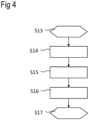
Figure 4 schematically shows a flow diagram of a method according to an exemplary embodiment. -
Figures 5, 6, 7 and8 each schematically show differentpredetermined input pulses 4 used in the method according to an exemplary embodiment. - The
system 14 according to the exemplary embodiment ofFigure 1 comprises asensing system 2 and areturn element 1 configured to be connected to an HVDC power transmission system. In particular, thereturn element 1 is connected to the HVDC power transmission system. Thesensing system 2 is connected to thereturn element 1. Thesensing system 2 is further connected to ananalyzing computing device 13. The analyzingcomputing device 13 is connected to thereturn element 1 via thesensing system 2. - In particular, the
return element 1 is arranged between the HVDCpower transmission system 3 and a reference potential, e.g. a ground potential. - The HVDC
power transmission system 3 particularly comprises aconverter 17. - The
sensing system 2 comprises anoutput unit 6 configured to providepredetermined input pulses 4, in particular physicalpredetermined input pulses 4, to thereturn element 1. Theoutput unit 6 comprises anamplifier 11 and acoupling capacitor 12, wherein thecoupling capacitor 12 is connected to thereturn element 1. In particular, a signal corresponding to thepredetermined input pulses 4 is provided by the analyzingcomputing device 13 to the amplifier, where the signal corresponding to thepredetermined input pulses 4 is amplified. The amplified signal corresponding to thepredetermined input pulses 4 is applied to thereturn element 1 via thecoupling capacitor 12. - The
sensing system 2 comprises aninput unit 7 configured to measure electrical properties of thereturn element 1. Theinput unit 7 comprises avoltage sensor device 8 configured to measure a voltage of thereturn element 1, a firstcurrent sensor device 9 configured to measure a current of thereturn element 1, and a secondcurrent sensor device 10 configured to measure a current of theoutput unit 6. - The
voltage sensor device 8 is in particular arranged between a node of thereturn element 1 connected to the coupling capacitor and a node of thereturn element 1 connected to the HVDCpower transmission system 3. The firstcurrent sensor device 9 is in particular arranged between the node of thereturn element 1 connected to the coupling capacitor and a node of thereturn element 1 connected to the reference potential. The second current sensor is arranged between the coupling capacitor and the amplifier, in particular on a side of the coupling capacitor. - The
voltage sensor device 8 is in particular arranged directly on thereturn element 1. The firstcurrent sensor device 9 is in particular arranged directly on thereturn element 1. - The analyzing
computing device 13 is configured to receive measurement signals from theinput unit 7 and is configured to provide the signal corresponding to thepredetermined input pulses 4 to theoutput unit 6. The analyzingcomputing device 13 is configured to perform the method described in connection withFigure 4 . - In particular, the
return element 1 of thesystem 14 ofFigure 1 is characteristic for an electrode line and thesystem 14 with thesensing system 2 is configured for a supervision of the electrode line. - The
system 14 according to the exemplary embodiment ofFigure 2 additionally comprises with respect to thesystem 14 ofFigure 1 , afurther converter 18. In particular, thereturn element 1 of thesystem 14 ofFigure 2 is characteristic for a dedicated metallic return, DMR, line arranged between theconverter 17 and thefurther converter 18. In particular, thesystem 14, i.e. the HDVCpower transmission system 3 has a bipolar configuration. - Method stages S1 to S12 according to the exemplary embodiment of
Figure 3 describe how a trained model is generated and deployed in theanalyzing computing device 13 shown inFigure 1 . The process according toFigure 3 comprises pre-performed method stages, being performed before the method described in connection withFigure 4 is carried out. The method according toFigure 3 is carried out, for example, on theanalyzing computing device 13 or an external computing device. - Method stage S1 is indicative of a start. In method stage S2 data characteristic of the
return element 1, thesensing system 2 and in particular the HVDCpower transmission system 3 are provided. The data are characteristic of an arrangement and properties of the electrical components of thereturn element 1, thesensing system 2 and in particular the HVDCpower transmission system 3. In this method stage, all the electrical components are considered as healthy. - In method stage S3 an initial electromagnetic model is generated based on the data provided in method stage S2. In method stage S4, at least one altered electromagnetic model is generated based on the initial electromagnetic model. For generating the altered electromagnetic model, a part of the initial electromagnetic model corresponding to a healthy electrical component is altered to a defective electrical component. Therefore, each altered electromagnetic model is characteristic of at least one or more defective parts. Different altered electromagnetic models are characteristic of at least one different defective part.
- In method stage S5, a plurality of
predetermined input pulses 4 is generated, wherein at least some or all of thepredetermined input pulses 4 are different from one another, particularly forming a predetermined input signal. In method stage S6, thepredetermined input pulses 4 generated in method stage S5 are provided to each of the initial electromagnetic model and the altered electromagnetic models. - In method stage S7, the
predetermined input pulses 4, i.e. the predetermined input signal, is/are provided to the initial electromagnetic model and the altered electromagnetic models, particularly to each of the altered electromagnetic models, wherein a response is simulated for each case. The response is characteristic of electronic properties of thesensing system 2. In particular, each response is characteristic of a voltage information of thevoltage sensor device 8, a first current information of the firstcurrent sensor device 9, and a second current information of the secondcurrent sensor device 10. The voltage information, the first current information and the second current information are each in particular represented by a time series of the respective simulated data. Each response can further comprise a classification if the response corresponds to a defective orhealthy return element 1 and/or a location of the defective part. - A trained model of the
return element 1 and thesensing system 2 is generated in method stage S8, wherein the trained model is generated dependent on the plurality of responses to the provision of the plurality ofpredetermined input pulses 4. - In method stage S9 the trained model is provided to the
analyzing computing device 13. In method stage S10, thepredetermined input pulses 4, particularly the predetermined input signal, is/are provided to theanalyzing computing device 13. - In step S11, the process for generating the trained model and deploying the trained model to the
analyzing computing device 13 is terminated. - In method stage S13 according to
Figure 4 , an initial electromagnetic model characteristic of thereturn element 1 and thesensing system 2 is provided, wherein thereturn element 1 has no defective parts, as described analogously in connection with method stage S3. - Subsequently, in method stage S14 at least one altered electromagnetic model is provided based on the initial electromagnetic model, wherein the
return element 1 has at least one defective part, as described analogously in connection with method stage S4. - Next, in method stage S15 a plurality of
predetermined input pulses 4 are provided, which are provided to the initial electromagnetic model and the altered electromagnetic model, wherein some of thepredetermined input pulses 4 are different from one another, as described analogously in connection with method stage S5 and S6. - In method stage S16, a trained model of the
return element 1 and thesensing system 2 is provided, wherein the trained model is generated dependent on a plurality of responses to the provision of the plurality ofpredetermined input pulses 4, as described analogously in connection with method stages S7 and S8. - In method stage S17 the state of the
return element 1 is detected dependent on some of thepredetermined input pulses 4 applied to thereturn element 1 and dependent on the trained model. For this, thepredetermined input pulses 4 are applied to thereturn element 1 via theoutput unit 6 described inFigure 1 . A response is measured via theinput unit 7 described inFigure 1 upon applying thepredetermined input pulses 4. The response is provided to the trained model, wherein the state is detected to be healthy or defective. - At least some of the
predetermined input pulses 4 according toFigure 5 have a different frequency from one another. Eachpredetermined input pulse 4 is characterized by oneperiod 15 of a predetermined frequency and a predetermined amplitude. Thepredetermined input pulses 4 are grouped into blocks 16. Eachblock 16 comprises at least some of thepredetermined input pulses 4 of the same frequency, such that eachblock 16 corresponds to one frequency. The frequencies ofdifferent blocks 16 are different from one another. This means that the predetermined input signal comprises theblocks 16, wherein the frequencies of theblocks 16 are different from one another. - According to
Figure 6 , consecutivepredetermined input pulses 4 are characteristic of the frequency sweep, wherein the frequency of at least some consecutivepredetermined input pulses 4 changes over time. The frequency of the consecutivepredetermined input pulses 4 increases gradually. - The
predetermined input pulses 4 according toFigure 7 have a different shape from one another. In particular, the shapes can be adapted dependent on the arrangement of the electronic components. - The
predetermined input pulses 4 according toFigure 8 , in particular the predetermined input signal, is/are characteristic of white noise. - The embodiments and exemplary embodiments described herein above can be combined accordingly.
-
- 1
- return element
- 2
- sensing system
- 3
- HVDC power transmission system
- 4
- predetermined input pulses
- 5
- predetermined input signal
- 6
- output unit
- 7
- input unit
- 8
- voltage sensor device
- 9
- first current sensor device
- 10
- second current sensor device
- 11
- amplifier
- 12
- coupling capacitor
- 13
- analyzing computing device
- 14
- system
- 15
- period
- 16
- block
- 17
- converter
- 18
- further converter
- S1..S17
- method stages
Claims (14)
- Method for detecting a state of a return element (1) connected to a sensing system (2) of a high voltage direct current, HVDC, power transmission system (3), comprising:- providing an initial electromagnetic model characteristic of the return element (1) and the sensing system (2), wherein the return element (1) has no defective parts,- providing at least one altered electromagnetic model based on the initial electromagnetic model, wherein the return element (1) has at least one defective part,- providing a plurality of predetermined input pulses (4), which are provided to the initial electromagnetic model and the altered electromagnetic model, wherein some of the predetermined input pulses (4) are different from one another,- providing a trained model of the return element (1) and the sensing system (2), wherein the trained model is generated dependent on a plurality of responses to the provision of the plurality of predetermined input pulses (4),- detecting the state of the return element (1) dependent on some of the predetermined input pulses (4) applied to the return element (1) and dependent on the trained model.
- Method according to claim 1, wherein- some of the predetermined input pulses (4) have a different frequency from one another, some consecutive predetermined input pulses (4) are characteristic of a frequency sweep and/or some of the predetermined input pulses (4) have a different pulse shape from one another, and/or- some of the predetermined input pulses (4) are characteristic of white noise.
- Method according to one of claims 1 or 2, wherein detecting the state of the return element (1) dependent on the trained model comprises:- detecting that the state of the return element (1) is healthy.
- Method according to one of claims 1 to 3, wherein detecting the state of the return element (1) dependent on the trained model comprises:- detecting that the state of the return element (1) is defective.
- Method according to claim 4, wherein- a location of the defective part of the return element (1) is provided.
- Method according to one of claims 1 to 5, wherein- the trained model is generated by a machine learning process.
- Method according to one of claims 1 to 6, wherein- the trained model is updated dynamically dependent on measurement data of the return element (1).
- Method according to one of claims 1 to 7, wherein- the sensing system (2) comprises an output unit (6) configured to provide the predetermined input pulses (4) to the return element (1), and- the sensing system (2) comprises an input unit (7) configured to measure electrical properties of the return element (1).
- Method according to claim 8, wherein- the input unit (7) comprises a voltage sensor device (8) configured to measure a voltage of the return element (1),- the input unit (7) comprises a first current sensor device (9) configured to measure a current of the return element (1), and- the input unit (7) comprises a second current sensor device (10) configured to measure a current of the output unit (6).
- Method according to one of claims 8 or 9, wherein- the output unit (6) comprises an amplifier (11) and a coupling capacitor (12), and- the coupling capacitor (12) is connected to the return element (1).
- Method according to one of claims 8 or 9, wherein- the output unit (6) comprises at least one converter of the transmission system.
- System (14) comprising- a return element (1),- a sensing system (2) connected to the return element (1), and- an analyzing computing device (13) which is configured to perform the method according to one of claims 1 to 11.
- Computer program product comprising instructions which, when the computer program is executed by a processor, cause the computer program to execute the method according to one of claims 1 to 11.
- Computer-readable storage medium on which the computer program product according to claim 13 is stored.
Priority Applications (2)
| Application Number | Priority Date | Filing Date | Title |
|---|---|---|---|
| EP23219183.3A EP4575528A1 (en) | 2023-12-21 | 2023-12-21 | Method for detecting a state of a return element connected to a sensing system of a high voltage direct current power transmission system, system, computer program product and computer-readable storage medium |
| PCT/EP2024/085869 WO2025131979A1 (en) | 2023-12-21 | 2024-12-12 | Method for detecting a state of a return element connected to a sensing system of a high voltage direct current power transmission system, system, computer program product and computer-readable storage medium |
Applications Claiming Priority (1)
| Application Number | Priority Date | Filing Date | Title |
|---|---|---|---|
| EP23219183.3A EP4575528A1 (en) | 2023-12-21 | 2023-12-21 | Method for detecting a state of a return element connected to a sensing system of a high voltage direct current power transmission system, system, computer program product and computer-readable storage medium |
Publications (1)
| Publication Number | Publication Date |
|---|---|
| EP4575528A1 true EP4575528A1 (en) | 2025-06-25 |
Family
ID=89308684
Family Applications (1)
| Application Number | Title | Priority Date | Filing Date |
|---|---|---|---|
| EP23219183.3A Pending EP4575528A1 (en) | 2023-12-21 | 2023-12-21 | Method for detecting a state of a return element connected to a sensing system of a high voltage direct current power transmission system, system, computer program product and computer-readable storage medium |
Country Status (2)
| Country | Link |
|---|---|
| EP (1) | EP4575528A1 (en) |
| WO (1) | WO2025131979A1 (en) |
Citations (3)
| Publication number | Priority date | Publication date | Assignee | Title |
|---|---|---|---|---|
| CN113514733A (en) * | 2021-09-07 | 2021-10-19 | 中国南方电网有限责任公司超高压输电公司广州局 | Fault positioning method and device, computer equipment and storage medium |
| US20210382103A1 (en) * | 2018-11-01 | 2021-12-09 | University Of Manitoba | Method for Determining Conductors Involved in a Fault on a Power Transmission Line and Fault Location Using Local Current Measurements |
| CN114580500A (en) * | 2022-01-28 | 2022-06-03 | 西安理工大学 | Multi-terminal direct-current transmission line fault diagnosis method based on WaveNet |
-
2023
- 2023-12-21 EP EP23219183.3A patent/EP4575528A1/en active Pending
-
2024
- 2024-12-12 WO PCT/EP2024/085869 patent/WO2025131979A1/en active Pending
Patent Citations (3)
| Publication number | Priority date | Publication date | Assignee | Title |
|---|---|---|---|---|
| US20210382103A1 (en) * | 2018-11-01 | 2021-12-09 | University Of Manitoba | Method for Determining Conductors Involved in a Fault on a Power Transmission Line and Fault Location Using Local Current Measurements |
| CN113514733A (en) * | 2021-09-07 | 2021-10-19 | 中国南方电网有限责任公司超高压输电公司广州局 | Fault positioning method and device, computer equipment and storage medium |
| CN114580500A (en) * | 2022-01-28 | 2022-06-03 | 西安理工大学 | Multi-terminal direct-current transmission line fault diagnosis method based on WaveNet |
Non-Patent Citations (7)
| Title |
|---|
| JEREMY SNEATH ET AL: "Fault Detection and Interruption in an Earthed HVDC Grid Using ROCOV and Hybrid DC Breakers", IEEE TRANSACTIONS ON POWER DELIVERY, 1 June 2016 (2016-06-01), New York, pages 973 - 981, XP055508950, Retrieved from the Internet <URL:https://mspace.lib.umanitoba.ca/bitstream/handle/1993/23939/Sneath_Jeremy.pdf?sequence=1> [retrieved on 20180924], DOI: 10.1109/TPWRD.2014.2364547 * |
| KHAN NOMAN MUJEEB ET AL: "A Novel Search and Rescue Optimization Algorithm Based Artificial Neural Network for Identification, Classification and Location of DC Fault in Two Terminal HVDC Transmission Systems", 2022 INTERNATIONAL CONFERENCE ON EMERGING TRENDS IN SMART TECHNOLOGIES (ICETST), IEEE, 23 September 2022 (2022-09-23), pages 1 - 6, XP034212263, DOI: 10.1109/ICETST55735.2022.9922910 * |
| LI WEI ET AL: "Influence of Deep Earth Resistivity on HVDC Ground-Return Currents Distribution", IEEE TRANSACTIONS ON POWER DELIVERY, IEEE SERVICE CENTER, NEW YORK, NY, US, vol. 32, no. 4, 1 August 2017 (2017-08-01), pages 1844 - 1851, XP011650601, ISSN: 0885-8977, [retrieved on 20170519], DOI: 10.1109/TPWRD.2016.2610443 * |
| LIN SHENG ET AL: "Fault Location Algorithm Based on Characteristic- Harmonic Measured Impedance for HVdc Grounding Electrode Lines", IEEE TRANSACTIONS ON INSTRUMENTATION AND MEASUREMENT, IEEE, USA, vol. 69, no. 12, 24 June 2020 (2020-06-24), pages 9578 - 9585, XP011819774, ISSN: 0018-9456, [retrieved on 20201109], DOI: 10.1109/TIM.2020.3004682 * |
| QIWEI GUO ET AL: "Faults predictions and analysis on reliability of the  660kV Ningdong HVDC power transmission system", ELECTRIC UTILITY DEREGULATION AND RESTRUCTURING AND POWER TECHNOLOGIES (DRPT), 2011 4TH INTERNATIONAL CONFERENCE ON, IEEE, 6 July 2011 (2011-07-06), pages 99 - 103, XP032039109, ISBN: 978-1-4577-0364-5, DOI: 10.1109/DRPT.2011.5993870 * |
| SINGH RAKESH KUMAR ET AL: "An Improved Method for Fault Analysis in Asymmetrical High Voltage Direct Current Transmission Lines", 2019 INTERNATIONAL CONFERENCE ON ELECTRICAL, ELECTRONICS AND COMPUTER ENGINEERING (UPCON), IEEE, 8 November 2019 (2019-11-08), pages 1 - 6, XP033703487, DOI: 10.1109/UPCON47278.2019.8980191 * |
| YULIN CHEN ET AL: "A Novel Fault Monitoring and Location System for HVDC Electrode Line", 2018 INTERNATIONAL CONFERENCE ON POWER SYSTEM TECHNOLOGY (POWERCON), IEEE, 6 November 2018 (2018-11-06), pages 2250 - 2256, XP033491835, DOI: 10.1109/POWERCON.2018.8601575 * |
Also Published As
| Publication number | Publication date |
|---|---|
| WO2025131979A1 (en) | 2025-06-26 |
Similar Documents
| Publication | Publication Date | Title |
|---|---|---|
| US20190312803A1 (en) | Detecting and locating process control communication line faults from a handheld maintenance tool | |
| EP2527854B1 (en) | Systems and methods for determining electrical faults | |
| GB2476246A (en) | Diagnosing an operation mode of a machine | |
| CN117741335A (en) | Analysis method for ground fault research and judgment of power distribution network | |
| CN118425677A (en) | Cable detection method and device | |
| KR20190020233A (en) | Simulated signal generating Apparatus and method for partial discharge simulation | |
| WO2025131979A1 (en) | Method for detecting a state of a return element connected to a sensing system of a high voltage direct current power transmission system, system, computer program product and computer-readable storage medium | |
| Roy et al. | Software reliability allocation of digital relay for transmission line protection using a combined system hierarchy and fault tree approach | |
| CN116087675A (en) | DC system ground fault detection method and device, storage medium and electronic equipment | |
| EP3611521A1 (en) | Apparatus for monitoring a condition of an electrical power transmisison medium | |
| KR101420729B1 (en) | Apparatus and method for diagnosing a ground network | |
| CN116068315A (en) | Network detection system for relay protection device | |
| Hamada et al. | Enhanced distance protection for HVDC lines using adaptive neuro-fuzzy inference systems | |
| US12474379B2 (en) | Arc-fault detection apparatus and method and electrical installation | |
| Kaiavathi et al. | Transformer fault diagnosis using fuzzy logic and neural network | |
| Boettcher et al. | Operational Risk Evaluation Of Cable Plugs Using An Automated Multisensor Classification System | |
| RU158297U1 (en) | AUTOMATED DEVICE FOR FUNCTIONAL MONITORING AND MONITORING OF PARAMETERS OF ELECTRIC CIRCUITS OF COMPLEX TECHNICAL PRODUCTS | |
| RU2580183C1 (en) | Method for diagnosing electric switching device | |
| Boettcher et al. | Algorithms for partial discharge monitoring of medium voltage cable plugs, using a multi-sensor expert system | |
| US6640264B1 (en) | Incremental state logic methodology and apparatus for logic based program control | |
| CN115980532B (en) | Wireless partial discharge sensor sample collection method and system | |
| CN119291388B (en) | Route selection method for judging fault point based on pull-out increment method | |
| CN118937861A (en) | A test device and method based on live lightning arrester testing and discharge counter verification | |
| RU2739386C2 (en) | Method for determination of insulation resistance reduction point | |
| Abd Rahman et al. | Partial discharge propagation inside a high voltage transformer winding: Comparison of measurement and simulation |
Legal Events
| Date | Code | Title | Description |
|---|---|---|---|
| PUAI | Public reference made under article 153(3) epc to a published international application that has entered the european phase |
Free format text: ORIGINAL CODE: 0009012 |
|
| STAA | Information on the status of an ep patent application or granted ep patent |
Free format text: STATUS: THE APPLICATION HAS BEEN PUBLISHED |
|
| AK | Designated contracting states |
Kind code of ref document: A1 Designated state(s): AL AT BE BG CH CY CZ DE DK EE ES FI FR GB GR HR HU IE IS IT LI LT LU LV MC ME MK MT NL NO PL PT RO RS SE SI SK SM TR |
|
| STAA | Information on the status of an ep patent application or granted ep patent |
Free format text: STATUS: REQUEST FOR EXAMINATION WAS MADE |
|
| 17P | Request for examination filed |
Effective date: 20251218 |