EP4575400A1 - Off-road routing - Google Patents
Off-road routing Download PDFInfo
- Publication number
- EP4575400A1 EP4575400A1 EP23219946.3A EP23219946A EP4575400A1 EP 4575400 A1 EP4575400 A1 EP 4575400A1 EP 23219946 A EP23219946 A EP 23219946A EP 4575400 A1 EP4575400 A1 EP 4575400A1
- Authority
- EP
- European Patent Office
- Prior art keywords
- obstacle
- vehicle
- data
- processing circuitry
- computer system
- Prior art date
- Legal status (The legal status is an assumption and is not a legal conclusion. Google has not performed a legal analysis and makes no representation as to the accuracy of the status listed.)
- Granted
Links
Images




Classifications
-
- G—PHYSICS
- G01—MEASURING; TESTING
- G01C—MEASURING DISTANCES, LEVELS OR BEARINGS; SURVEYING; NAVIGATION; GYROSCOPIC INSTRUMENTS; PHOTOGRAMMETRY OR VIDEOGRAMMETRY
- G01C21/00—Navigation; Navigational instruments not provided for in groups G01C1/00 - G01C19/00
- G01C21/38—Electronic maps specially adapted for navigation; Updating thereof
- G01C21/3804—Creation or updating of map data
- G01C21/3807—Creation or updating of map data characterised by the type of data
- G01C21/3826—Terrain data
-
- B—PERFORMING OPERATIONS; TRANSPORTING
- B60—VEHICLES IN GENERAL
- B60W—CONJOINT CONTROL OF VEHICLE SUB-UNITS OF DIFFERENT TYPE OR DIFFERENT FUNCTION; CONTROL SYSTEMS SPECIALLY ADAPTED FOR HYBRID VEHICLES; ROAD VEHICLE DRIVE CONTROL SYSTEMS FOR PURPOSES NOT RELATED TO THE CONTROL OF A PARTICULAR SUB-UNIT
- B60W40/00—Estimation or calculation of non-directly measurable driving parameters for road vehicle drive control systems not related to the control of a particular sub unit, e.g. by using mathematical models
- B60W40/02—Estimation or calculation of non-directly measurable driving parameters for road vehicle drive control systems not related to the control of a particular sub unit, e.g. by using mathematical models related to ambient conditions
- B60W40/06—Road conditions
-
- E—FIXED CONSTRUCTIONS
- E02—HYDRAULIC ENGINEERING; FOUNDATIONS; SOIL SHIFTING
- E02F—DREDGING; SOIL-SHIFTING
- E02F9/00—Component parts of dredgers or soil-shifting machines, not restricted to one of the kinds covered by groups E02F3/00 - E02F7/00
- E02F9/20—Drives; Control devices
- E02F9/2025—Particular purposes of control systems not otherwise provided for
- E02F9/2045—Guiding machines along a predetermined path
-
- E—FIXED CONSTRUCTIONS
- E02—HYDRAULIC ENGINEERING; FOUNDATIONS; SOIL SHIFTING
- E02F—DREDGING; SOIL-SHIFTING
- E02F9/00—Component parts of dredgers or soil-shifting machines, not restricted to one of the kinds covered by groups E02F3/00 - E02F7/00
- E02F9/20—Drives; Control devices
- E02F9/2025—Particular purposes of control systems not otherwise provided for
- E02F9/205—Remotely operated machines, e.g. unmanned vehicles
-
- E—FIXED CONSTRUCTIONS
- E02—HYDRAULIC ENGINEERING; FOUNDATIONS; SOIL SHIFTING
- E02F—DREDGING; SOIL-SHIFTING
- E02F9/00—Component parts of dredgers or soil-shifting machines, not restricted to one of the kinds covered by groups E02F3/00 - E02F7/00
- E02F9/20—Drives; Control devices
- E02F9/2025—Particular purposes of control systems not otherwise provided for
- E02F9/2054—Fleet management
-
- E—FIXED CONSTRUCTIONS
- E02—HYDRAULIC ENGINEERING; FOUNDATIONS; SOIL SHIFTING
- E02F—DREDGING; SOIL-SHIFTING
- E02F9/00—Component parts of dredgers or soil-shifting machines, not restricted to one of the kinds covered by groups E02F3/00 - E02F7/00
- E02F9/26—Indicating devices
- E02F9/261—Surveying the work-site to be treated
- E02F9/262—Surveying the work-site to be treated with follow-up actions to control the work tool, e.g. controller
-
- G—PHYSICS
- G01—MEASURING; TESTING
- G01C—MEASURING DISTANCES, LEVELS OR BEARINGS; SURVEYING; NAVIGATION; GYROSCOPIC INSTRUMENTS; PHOTOGRAMMETRY OR VIDEOGRAMMETRY
- G01C21/00—Navigation; Navigational instruments not provided for in groups G01C1/00 - G01C19/00
- G01C21/26—Navigation; Navigational instruments not provided for in groups G01C1/00 - G01C19/00 specially adapted for navigation in a road network
- G01C21/34—Route searching; Route guidance
- G01C21/3407—Route searching; Route guidance specially adapted for specific applications
-
- G—PHYSICS
- G01—MEASURING; TESTING
- G01C—MEASURING DISTANCES, LEVELS OR BEARINGS; SURVEYING; NAVIGATION; GYROSCOPIC INSTRUMENTS; PHOTOGRAMMETRY OR VIDEOGRAMMETRY
- G01C21/00—Navigation; Navigational instruments not provided for in groups G01C1/00 - G01C19/00
- G01C21/26—Navigation; Navigational instruments not provided for in groups G01C1/00 - G01C19/00 specially adapted for navigation in a road network
- G01C21/34—Route searching; Route guidance
- G01C21/3453—Special cost functions, i.e. other than distance or default speed limit of road segments
- G01C21/3461—Preferred or disfavoured areas, e.g. dangerous zones, toll or emission zones, intersections, manoeuvre types or segments such as motorways, toll roads or ferries
Definitions
- the disclosure relates generally to routing planning.
- the disclosure relates to off-road routing.
- the disclosure can be applied to heavy-duty vehicles, such as trucks, buses, and construction equipment, among other vehicle types.
- heavy-duty vehicles such as trucks, buses, and construction equipment, among other vehicle types.
- the disclosure may be described with respect to a particular vehicle, the disclosure is not restricted to any particular vehicle.
- a computer system comprising processing circuitry.
- the processing circuitry is configured to obtain map data for route planning within a confined off-road area, obtain, based on sensor data of a first off-road vehicle, position data and size data of a first obstacle within the confined off-road area, obtain classification data of the first obstacle, determine a first required traction capability for traversing the first obstacle based on the size data and the classification data, and update the map data with the position data, size data and the first required traction capability for traversing the first obstacle.
- a technical benefit may include ensuring that map data of the confined off-road area is up to date with required traction capabilities for traversing the obstacles. This enables vehicles routed in the confined off-road area to ignore traversable obstacles and avoid obstacles that cannot be traversed by a specific vehicle.
- the processing circuitry is further configured to obtain the classification data based on engagement of the first obstacle by a work attachment of the first off-road vehicle.
- a technical benefit may include providing accurate classification data comprising details not possible to accurately estimate without engagement of the object, such as weight, viscosity etc.
- the processing circuitry is further configured to determine a second required traction capability and an associated minimum travel speed for traversing the first obstacle based on the size data and the classification data, and update the map data with the second required traction capability and the associated minimum travel speed.
- a technical benefit may include providing further accurate map data relevant for traction capabilities of a specific vehicle.
- the processing circuitry is further configured to estimate speeds of the second vehicle at positions of obstacles of the routing map data, and remove obstacles from the routing map data having an associated minimum travel speed being greater than the estimated speed of the second vehicle at positions of the associated obstacle and wherein the second required traction capability of the obstacle is lower than the traction capability of the second vehicle.
- a technical benefit may include providing further accurate map data relevant for traction capabilities of a specific vehicle.
- the processing circuitry is further configured to determine a third required traction capability and an associated maximum travel speed for traversing the first obstacle based on the size data and the classification data, and update the map data with the third required traction capability and the associated maximum travel speed.
- a technical benefit may include providing further accurate map data relevant for traction capabilities of a specific vehicle.
- the processing circuitry is further configured to obtain a target destination and a current location of the second vehicle within the confined off-road area, determine a route for the second vehicle based on a current location of the second vehicle, the target destination and the routing map data, and provide the route to the second vehicle.
- a technical benefit may include provisioning of an efficient route in a stochastic environment where only obstacles relevant for the specific second vehicle are considered.
- the classification data comprises one or more of an indication of a weight of the first obstacle, and indication of a viscosity of the first obstacle, an indication of a movability of the first obstacle, an indication of a type of the first obstacle.
- the size data comprises at least one of an indication of a height of the first obstacle, an indication of a depth of the first obstacle, or an indication of a circumference of the first obstacle.
- the confined off-road area comprises at least a portion of a mining site.
- the processing circuitry is further configured to obtain position data and size data of the first obstacle based on sensor data of the work attachment of the first off-road vehicle.
- the processing circuitry is further configured to obtain: a request for route planning of a second vehicle comprising an indicator of a traction capability of the second vehicle, determine routing map data for the second vehicle based on the map data, wherein obstacles having a first required traction capability being lower than or equal to the traction capability of the second vehicle are removed from the routing map data; determine a second required traction capability and an associated minimum travel speed for traversing the first obstacle based on the size data and the classification data, and update the map data with the second required traction capability and the associated minimum travel speed; estimate speeds of the second vehicle at positions of obstacles of the routing map data, and remove obstacles from the routing map data having an associated minimum travel speed being greater than the estimated speed of the second vehicle at positions of the associated obstacle and wherein the second required traction capability of the obstacle is lower than the traction capability of the second vehicle; determine a third required traction capability and an associated maximum travel speed for traversing the first obstacle based on the size data and the classification data, and update the map data with
- a vehicle comprising the computer system of the first aspect and a work attachment is presented.
- a computer-implemented method comprises obtaining, by a processing circuitry of a computer system, map data for route planning within a confined off-road area, obtaining, by the processing circuitry of the computer system, based on sensor data of a first off-road vehicle, position data and size data of a first obstacle within the confined off-road area, obtaining, by the processing circuitry of the computer system, based on engagement of the first obstacle by a work attachment of the first off-road vehicle, classification data of the first obstacle, determining, by the processing circuitry of the computer system, a first required traction capability for traversing the first obstacle based on the size data and the classification data, and updating, by the processing circuitry of the computer system, the map data with the position data, size data and the first required traction capability of the first obstacle.
- a computer program product comprising program code for performing, when executed by a processing circuitry, the method of the third aspect.
- a non-transitory computer-readable storage medium comprising instructions, which when executed by a processing circuitry, cause the processing circuitry to perform the method of the third aspect.
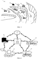
- FIG. 1 an exemplary confined off-road area 1 is shown.
- the confined off-road area 1 is a quarry, and this will be used to exemplify the teachings of the present disclosure.
- the present disclosure is in no way limited to confined off-road areas 1 in the form of quarries, but other confined off-road areas are will within the scope such as, but not limited to, areas of logging, mining etc.
- the confined off-road area 1 of FIG. 1 quarry comprising a fist level i , a second level ii , a third level iii , and a fourth level iv , wherein the first level i is a top level and the fourth level iv is a bottom level.
- loaders 10 In the quarry, loaders 10 (first vehicles 10 ) are operating to load material onto haulers 20 (second vehicles 20 ).
- second vehicles 20 In FIG. 1 , two types of haulers 20 are shown, an autonomous hauler and an operator controlled hauler.
- Other vehicles 30 third vehicles 30 ) may be present in the quarry such as trucks or other vehicles for transportation of personnel.
- Scattered throughout the confined off-road area 1 are obstacles 5.
- the obstacles 5 may be puddles of mud, blocks of stone, wheel tracks, damaged or stuck vehicles etc. Any routing (manual or autonomous) of vehicles 10, 20, 30 within the confined off-road area 1 is advantageously configured to avoid the obstacles 5.
- map data of the confined off-road area 1 generally comprise locations of obstacles 5 within the confined off-road area 1.
- obstacles 5 may change in nature, disappear och occur seemingly randomly within the confined off-road area 1 .
- a sudden rain may create deep puddles and muddy roads that completely change the map data when it comes to obstacles.
- a few hours of sun may dry out a previously muddy road to create difficult (or impossible) to traverse wheel tracks.
- the inventors behind the present disclosure have realized, through inventive thinking and thorough research, that it is advantageous to update obstacle data of the map data not only based on new obstacles 5 , but also based on specific features of the obstacle 5.
- FIG. 2 a schematic view of a computer system 100 is shown.
- the computer system 100 comprises processing circuitry 110 configured to perform, or cause performance of one or more actions, tasks or features relating to teachings of the present disclosure.
- the computer system 100 is in communication, advantageously wirelessly, with one or more vehicles 10, 20, 30 within the confined off-road area 1.
- the computer system 100 may, in some examples, further be in communication with a cloud server 40.
- the vehicles 10, 20, 30 comprises processing circuitry 11, 21, 31 for controlling, or causing communication, with the computer system 100.
- a vehicle 10, 20, 30 of the present disclosure comprises one or more propulsion sources.
- the propulsion source may be any suitable propulsion source exemplified by, but not limited to, one or more or a combination of an electrical motor, a combustion engine such as a diesel, gas or gasoline powered engine.
- the vehicle 10, 20, 30 further comprises an energy source suitable for providing energy for the propulsion source.
- the vehicle 10, 20, 30 further comprises sensor circuitry arranged to detect, measure, sense or otherwise obtain data relevant for operation of the vehicle 10, 20, 30.
- the data relevant for operation of the vehicle 10, 20, 30 may be exemplified by, but not limited to, one or more of a speed of the vehicle 10, 20, 30 , a weight of the vehicle 10, 20, 30 , an inclination of the vehicle 10, 20, 30 , a status (state of charge, fuel level etc.) of the energy source of the vehicle 10, 20, 30 etc.
- the vehicle 10, 20, 30 may comprise communications circuitry configured for communication with, to the vehicle 10, 20, 30 , external devices.
- the communications circuitry is advantageously a communications circuitry configurable to provide a wireless communication interface exemplified by, but not limited to, Wi-Fi, Bluetooth, Zigbee, Z-Wave, LoRa, Sigfox, 2G (GSM, CDMA), 3G (UMTS, CDMA2000), 4G (LTE), 5G (NR) etc.
- the vehicles 10, 20, 30 may communicate directly with each other and/or meshed through computer system 100, or other vehicles 10, 20, 30. Communication with the other vehicles 10, 20, 30 may be provided by the previously mentioned wireless interfaces, and/or any suitable vehicle-to-vehicle (V2V) communications protocol exemplified by, but not limited to Dedicated Short-Range Communications (DSRC), Cellular Vehicle-to-Everything (C-V2X), IEEE 802.11p, LTE-V (LTE-V2X), 5G NR (New Radio) V2X, etc.
- DSRC Dedicated Short-Range Communications
- C-V2X Cellular Vehicle-to-Everything
- IEEE 802.11p LTE-V
- LTE-V2X Long Term Evolution-V
- 5G NR New Radio
- the vehicle 10, 20, 30 may further be operatively connected to a Global Navigation Satellite System (GNSS) exemplified by, but not limited to, global positioning system (GPS), Globalnaya Navigatsionnaya Sputnikovaya Sistema (GLONASS), Galileo, BeiDou Navigation Satellite System, Navigation with Indian Constellation (NavIC) etc.
- GNSS Global Navigation Satellite System
- GPS global positioning system
- GLONASS Globalnaya Navigatsionnaya Sputnikovaya
- Galileo BeiDou Navigation Satellite System
- NavIC Navigation with Indian Constellation
- the processing circuitry 110 of the computer system 100 comprises a processing circuitry 11 of one or more loaders 10 within the confined off-road area 1.
- the processing circuitry 110 of the computer system 100 may further comprises a processing circuitry 21 of one or more haulers 20 within the confined off-road area 1.
- the processing circuitry 110 of the computer system 100 may further comprises a processing circuitry 31 of one or more other vehicles 30 within the confined off-road area 1.
- FIG. 4 an exemplary loader 10 is shown.
- the loader 10 comprises processing circuitry 11 configured to e.g. communicate with the computer system 100 or provide, or cause provisioning of, any other tasks, features or functions presented herein being relevant for the loader 10.
- the loader 10 further comprises sensor circuitry 13 configured to, as mentioned, detect, measure, sense or otherwise obtain data relevant for operation of the loader 10.
- the loader 10 further comprises a work attachment 15. In FIG.
- the work attachment 15 is shown as a bucket attachment, but the work attachment 15 may be any suitable work attachment 15 such as, but not limited to a crane attachment, a fork attachment, an auger attachment, a grapple attachment, a sweeper attachment, a mulcher attachment, a breaker attachment (hydraulic hammer attachment), a blade attachment etc.
- the loader 10 comprises more than one work attachment 15.
- any vehicle 10, 20, 30 of the present disclosure may comprise a suitable work attachment 15.
- any combination of vehicle 10, 20, 30 and work attachment 15 may be utilized to achieve effects, and functions presented herein.
- the route planner 200 may be implemented as part of the computer system 100, and/or the processing circuitry 110 of the computer system 100 may be configured to perform, or cause performance of the functions, features or examples of the route planner 200.
- the route planner 200 is configured to obtain map data 260 for route planning within the confined off-road area 1.
- the map data 260 may be obtained from a storage device that may e.g. be external to the route planner 200, connected to the cloud server 40 and/or form part of the computer system 100.
- the map data 260 may comprise, or is configured to comprise, obstacle data 270.
- the obstacle data 270 is associated with obstacles 5 within the confined off-road area 1.
- the obstacle data 270 will be further explained in the following.
- the map data 260 may further comprise a routing target 285.
- the routing target 285 (navigation target, navigation goal, routing destination etc.) indicate a destination for a vehicle 10, 20, 30 within the confined off-road area 1. In some examples, the routing target 285 is separate from the map data 260.
- the route planner 200 may comprise an obstacle sensor 210.
- the obstacle sensor 210 may be configured to obtain position data 212 and/or size data 214 of an obstacle 5 within the confined off-road area 1.
- the positon data 212 of the obstacle 5 and the size data 214 of the obstacle 5 may be obtained based on sensor data 13'.
- the sensor data 13' may be provided by the sensor circuitry 13 of the first vehicle 10.
- the positon data 212 of the obstacle 5 is obtained from a GPS sensor of the first vehicle 10 at a point in time when the first vehicle 10 is at the obstacle 5.
- the positon data 212 of the obstacle 5 is obtained based on a location of the work attachment 15 of the first vehicle 10.
- the location of the work attachment 15, e.g. a bucket of a loader 10 is generally accurately known at the loader 10 based on GPS data of the loader 10 and the relative location of the bucket tip in relation to the location of the GPS sensor.
- the size data 214 of the obstacle 5 may be estimated by visual inspection of the obstacle 5 and/or by the first vehicle 10 traveling around the obstacle 5 sensing an outline, or a plurality of points at a circumference of the obstacle 5.
- the bucket may be placed at a top of the obstacle 5 to obtain a height of the obstacle 5, or immersed into the obstacle 5 (hope, puddle etc.) to obtain a depth of the obstacle 5.
- the size data 214 may comprise any data suitable to indicate a size of the obstacle 5.
- the size data 215 may comprise a height of the obstacle 5, an indication of a depth of the obstacle 5, and/or an indication of a circumference of the obstacle 5.
- the route planner 200 further comprises a classification obtainer 220.
- the classification obtainer 220 may a communications device and/or a processing device configured to obtain classification data 225 of the obstacle 5.
- the classification obtainer 220 may be configured to obtain image data of the obstacle 5, process the image data (or provide the image data for processing) to determine classification data 225 based on e.g. image recognition and similar processing techniques.
- the classification data 225 of the obstacle 5 may comprise a type of the obstacle 5.
- the type of the obstacle 5 may be one of e.g.
- the classification data 225 of the obstacle 5 may additionally, or alternatively, comprise one or more of an indication of a weight of the obstacle 5, and indication of a viscosity of the obstacle 5, an indication of a movability of the obstacle 5 and/or an indication of a type of the obstacle 5.
- the classification obtainer 220 is an obstacle engager 220.
- the obstacle engager 220 is configured to engage/touch obstacles 5 to determine classification data 225 of the obstacle 5.
- the obstacle engager 220 may engage the obstacle 5 with the work attachment 15 of the first vehicle 10.
- classification data 225 may be determined by an operator of a loader 10 engaging an obstacle 5 by the work attachment 15 of the loader 10, i.e. the bucket.
- the operator may push the obstacle 5 with the bucket and the obstacle engager 220 may obtain a torque or corresponding exerted by the propulsion source of the loader 10.
- the loader 10 may try and lift the obstacle 5 and weight sensors 13 of the bucket may be utilized to estimate a weight of the obstacle 5.
- the type of the obstacle 5 may be provided directly by an operator of the vehicle 10, or by the operator in conjunction with data obtained by engaging the obstacle 5.
- the operator may determine of the puddle is deep enough to be an obstacle 5 and if the puddle is filled with water or mud. Based on how water or mud trickles from the bucket when it is removed from the puddle, a viscosity may be determined.
- classification data 225 is not necessarily absolute data in absolute terms such as newton-second per square meter N. s/m 2 for viscosity, but may relative terms such as percentage % in reference to a known measure, or subjective such as high, medium, low, 0-100, or any other data suitable for conveying the specific classification data 225.
- Classifying obstacles 5 based on their characteristics helps in understanding their potential impact on vehicle and equipment performance. As will be explained, this helps in deciding strategies for safely navigating through the confined off-road area 1.
- the router planner 200 further comprises a traction determiner 230.
- the traction determiner 230 is configured to determine a first required traction capability 231 for traversing the obstacle 5 based on the size data 214 and the classification data 225.
- the first required traction capability 231 is provided in a format, or convertible to a format, that may be mapped to traction capabilities 255 of vehicles 10, 20, 30 operating within the confined off-road area 1.
- the first traction capability of a vehicle 10, 20, 30 may be determined based on e.g.
- chassis a robust chassis and off-road suspension system generally allow a vehicle to absorb shocks and impacts while maintaining stability
- suspension a well-designed suspension helps keep all wheels in contact with the ground, improving traction and maneuverability
- ground clearance a distance between the lowest point of the vehicle's 10, 20, 30 undercarriage and the ground, higher ground clearance prevents the vehicle 10, 20, 30 from getting stuck on uneven surfaces or high obstacles
- traction and differential systems vehicles provided with features like all-wheel drive (AWD), four-wheel drive (4WD), or differential locks generally have better traction on slippery or uneven surfaces compared to vehicles 10, 20, 30 without such systems
- tires off-road tires with aggressive tread patterns provide better grip on challenging surfaces like mud, sand, and rocks
- water fording depth some off-road vehicles have the capability to ford through water bodies without causing damage to vehicle components
- engine power and torque sufficient power and torque enable a vehicle 10, 20, 30 to overcome resistance caused by challenging terrains and obstacles
- weight distribution a well-balanced weight distribution helps maintain stability while traversing obstacles, especially on uneven terrain
- the traction determiner 230 may be configured to determine the first required traction capability 231 to indicate a ground clearance of at least 60 cm, at least 4WD and tires having a diameter greater than 55 cm.
- the first required traction capability 231 may be one summarized required traction capability indicator, a set of required traction capabilities or indicate a specific type of vehicles 10, 20, 30.
- the exemplified obstacle 5 may be possible to traverse by loaders 10 and haulers 20 but not by other vehicles 30.
- the traction determiner 230 may further be configured to determine a second required traction capability 232 for traversing the obstacle 5 based on the size data 214 and the classification data 225.
- the second required traction capability 232 is associated with a minimum travel speed 235.
- the traction determiner 230 may configured to determine the minimum travel speed 235 associated with the second required traction capability 232.
- the minimum travel speed 235 is a predetermined travel speed that may be configured per vehicle 10, 20, 30 based on e.g. requirement for the confined off-road area 1, fuel efficiency, vehicle utilization etc.
- the second traction capability 232 is beneficial as it allows vehicles to traverse a specific obstacle 5 if a travel speed of the vehicle 10, 20, 30 is greater than the minimum travel speed 235 associated with the obstacle 5.
- the size data 214 of the obstacle indicate a depth of 20 cm and a width of 6 m
- the classification data 225 indicate that the obstacle 5 is a mud pit.
- the first required traction capability 231 indicates that only loaders 10 and haulers 20 are capable of traversing the obstacle. However, assuming that other vehicles 30, for instance a truck, are traveling at a speed greater than 20 km/h, also other vehicles 30 are able to traverse the mud pit.
- the traction determiner 230 may determine the second required traction capability 232 to indicate that all vehicles 10, 20, 30 may traverse the obstacle 5 and determine the minimum travel speed 235 associated with the second required traction capability 232 to be 20 km/h.
- the traction determiner 230 may further be configured to determine a third required traction capability 233 for traversing the obstacle 5 based on the size data 214 and the classification data 225.
- the third required traction capability 233 is associated with a maximum travel speed 236.
- the traction determiner 230 may configured to determine the maximum travel speed 236 associated with the third required traction capability 233.
- the maximum travel speed 236 is a predetermined travel speed that may be configured per vehicle 10, 20, 30 based on e.g. requirement for the confined off-road area 1, fuel efficiency, vehicle utilization etc.
- the third traction capability 233 is beneficial as it allows vehicles to traverse a specific obstacle 5 if a travel speed of the vehicle 10, 20, 30 is lower than the maximum travel speed 236 associated with the obstacle 5.
- the size data 214 of the obstacle indicate a depth of 35 cm and a width of 4 m
- the classification data 225 indicate that the obstacle 5 is a puddle (pool of water).
- the first required traction capability 231 indicates that only loaders 10 and haulers 20 are capable of traversing the obstacle. However, assuming that other vehicles 30, for instance a truck, are traveling at a speed greater than 20 km/h would water board and skid across the obstacle 5. But the same truck, if travelling at speeds below 20 km/h, would sink and achieve good traction at the bottom of the puddle.
- the traction determiner 230 may determine the third required traction capability 233 to indicate that all vehicles 10, 20, 30 may traverse the obstacle 5 and determine the maximum travel speed 236 associated with the third required traction capability 232 to be 20 km/h.
- the route planner 200 may update the map data 260 with the position data 212 and/or the size data 214 of the obstacle 5. If the obstacle 5 is not already associated with obstacle data 270 of the map data 260, new obstacle data 270 may be created comprising data position data 212 and optionally size data 214 provided by the obstacle sensor 210.
- the route planner 200 may update the map data 260 with the classification data 225 of the obstacle 5, and the first required traction capability 231 associated with the obstacle 5. If determined, the route planner 200 may update the map data 260 with the second required traction capability 232 and associated minimum travel speed 225, and/or the third required traction capability 233 and associated maximum travel speed 226. This allows the map data 260 to be utilized for route planning by any device having access to the map data 260.
- the route planner 200 may comprise a routing map data determiner 240.
- the routing map data determiner 240 is configured to provide routing map data 245.
- the routing map data determiner 240 may be configured to provide routing map data 245 for a specific vehicle 10, 20, 30, a specific type of vehicle 10, 20, 30 or for vehicles 10, 20, 30 having a specific traction capability 255.
- the routing map data determiner 240 is configured to obtain a routing request 280, i.e. a request for route planning within the confined off-road area 1.
- the routing request 280 comprises an indication of a traction capability 255 of the vehicle 10, 20, 30 to be routed.
- the traction capability 255 may be a simple indication of a type of vehicle 10, 20, 30.
- the traction capability 255 may comprise one or more of an indication of a chassis of vehicle 10, 20, 30, a suspension of vehicle 10, 20, 30, a ground clearance of vehicle 10, 20, 30, a traction system of vehicle 10, 20, 30, a differential systems of vehicle 10, 20, 30 , a differential lock configuration of vehicle 10, 20, 30, tires of vehicle 10, 20, 30 , a water fording depth of vehicle 10, 20, 30, an engine power of vehicle 10, 20, 30 , an engine torque of vehicle 10, 20, 30, a weight distribution of vehicle 10, 20, 30 and/or a structural strength of vehicle 10, 20, 30 .
- the routing map data determiner 240 may be configured to determine speed estimates 243 of the vehicle 10, 20, 30 of the routing request 280 at locations of obstacles 5 of the routing map data 245. If the estimated speed 243 is greater than the minimum travel speed 235 associated with a specific obstacle 5 and the second required traction capability 232 of the specific obstacle 5 is lower than, or equal to, the traction capability of the vehicle 10, 20, 30 of the routing request 280, the specific obstacle 5 may be removed from the routing map data 245.
- any comparison, measurement, or limit generally includes sufficient margin for error to ensure, within reason, that required traction capabilities 231, 232, 233 never are violated.
- the routing map data 245 may be provided to the computer system 100 for future route planning. In some examples, new (updated) routing map data 245 may be provided each time an obstacle 5 us updated or modified by the route planner 200.
- the routing map data 245 may be stored at suitable storage circuitry of the computer system 100. Additionally, or alternatively, the routing map data 245 may be provided to the vehicle 10, 20, 30 of the routing request 280.
- the route planner 200 is utilizing dynamically optimized paths. This is beneficial in areas and location wherein routes change often. This is the case in mining areas where the loader 10 works at different locations and the hauler 20 is requested to arrive at different locations each load cycle.
- the cost function L typically distance or time
- the optimization may be carried out in two steps where a first step comprise providing an initial guess using e.g. a graph searching method such as A* which is followed by solving of a continuous optimization method such as a nonlinear program.
- a first step comprise providing an initial guess using e.g. a graph searching method such as A* which is followed by solving of a continuous optimization method such as a nonlinear program.
- a challenge is that the environment of the confined off-road area 1 may change a lot over a short period of time.
- One such example are the benches where material is extracted in a mine (see e.g. FIG. 1 ).
- the roads may be solid, rock hard roads that are easy to traverse.
- the confined off-road area 1 may get almost inaccessible due to a vast amount of mud and a lot of deep puddles.
- the first step is to secure that potential obstacles 5 are input to the computer system 100.
- the operator of the loader 10 may categorize the obstacle 5, for instance, how deep the puddle is or how big a specific rock is, so that they computer system 100 may take the obstacle 5 under consideration computing routes for different kind of vehicles 10, 20, 30 of the confined off-road area 1, specifically since different vehicles 10, 20, 30 will have different traction capabilities, i.e. different terrain ability. As a consequence, an obstacle 5 that is classified as an obstacle 5 for a hauler 30 may not be classified as an obstacle 5 for a hauler 10.
- FIG. 6 a block diagram of the computer system 100 according to one example is shown.
- the computer system 100 comprises processing circuitry 110.
- the processing circuitry 110 is configured to obtain map data 260 for route planning within the confined off-road area 1.
- the processing circuitry 110 is further configured to obtain, based on sensor data 13' of a first off-road vehicle 10, position data 212 and size data 214 of a first obstacle 5 within the confined off-road area 1.
- the processing circuitry 110 is further configured to obtain, based on engagement of the first obstacle 5 by the work attachment 15 of the first off-road vehicle 10, classification data 225 of the first obstacle 5.
- the processing circuitry 110 is further configured to determine the previously presented first required traction capability 231 for traversing the first obstacle 5 based on the size data 214 and the classification data 225, and to update the map data 260 with the position data 212, size data 214 and the first required traction capability 231 for traversing the first obstacle 5.
- the computer system 100 shown in FIG. 6 may be modified, expanded and or configured to perform, or cause performance of any of the features, functions or examples presented herein, specifically those presented with reference to FIG. 5 .
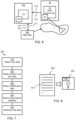
- FIG. 7 a block diagram of an exemplary method 300 is shown.
- the method 300 may be a computer implemented method 300, and functions and features of the method 300 may be performed by the processing circuitry 110 of the computer system 100.
- the method 300 comprises obtaining 310 map data 260 for route planning within the confined off-road area 1.
- the map data 310 may be obtained by any interface or from any location, device, function or processing circuitry 110 presented herein.
- the method 300 further comprises obtaining 320 position data 212 and size data 214 of a first obstacle 5 within the confined off-road area 1.
- the position data 212 and size data 214 of the first obstacle 5 may be obtained 320 based on any interface or from any location, device, function or processing circuitry 110 presented herein.
- the position data 212 and size data 214 of the first obstacle 5 is obtained 320 based on sensor data 13' of a first off-road vehicle 10.
- the method 300 further comprises obtaining 330 classification data 225 of the first obstacle 5.
- the classification data 225 may be obtained based on any interface or from any location, device, function or processing circuitry 110 presented herein. In one example, the classification data 225 is obtained based on engagement of the first obstacle 5 by a work attachment 15 of the first off-road vehicle 10.
- the method 300 further comprises determining 340 a first required traction capability 231 for traversing the first obstacle 5.
- the first required traction capability 231 may be determined according to any function, feature or example presented herein. In one example, the first required traction capability 231 is determined based on the size data 214 and the classification data 225.
- the method 300 further comprises updating 350 the map data 260 with the data associated with the first obstacle 5.
- the map data 260 may be updated with any data associated with the first obstacle 5 mentioned herein. In one example, the map data 260 is updated with position data 212, size data 214 and the first required traction capability 231 of the first obstacle 5.
- the computer program product 400 comprises a computer program 600 and a non-transitory computer readable medium 500.
- the computer program 600 may be stored on the computer readable medium 500.
- the computer readable medium 500 is, in FIG. 8 , exemplified as a vintage 5,25" floppy disc, but may be embodied as any suitable non-transitory computer readable medium such as, but not limited to, hard disk drives (HDDs), solid-state drives (SSDs), optical discs (e.g., CD-ROM, DVD-ROM, CD-RW, DVD-RW), USB flash drives, magnetic tapes, memory cards, Read-Only Memories (ROM), network-attached storage (NAS), cloud storage etc.
- HDDs hard disk drives
- SSDs solid-state drives
- optical discs e.g., CD-ROM, DVD-ROM, CD-RW, DVD-RW
- USB flash drives magnetic tapes
- memory cards Read-Only Memories (ROM), network-attached storage (NAS), cloud storage
- the computer program 600 comprises instruction 610 e.g. program instruction, software code, that, when executed by processing circuitry cause the processing circuitry to perform the method 300 introduced herein with reference to FIG. 7 .
- instruction 610 e.g. program instruction, software code
- FIG. 9 a schematic view of a site management system 800 is shown.
- the site management system 800 may comprise (or be operatively connected to) the computer system 100 as presented herein.
- the site management system 800 may obtain any data available to the computer system 100.
- the site management system 800 may configured the computer system 100 to perform or cause any action or feature described herein.
- the site management system 800 may be a software system, a hardware system or a system of both software and hardware.
- the site management system 800 may be configured to assist in planning, managing, and optimizing operation of an associated site, i.e. the confined off-road area 1.
- the site management system 800 may be configured to e.g. schedule and monitor equipment maintenance and repair, inventory levels of materials and supplies, production and productivity metrics, safety and compliance data, employee training and development records etc.
- the site management system 800 may be configured to provide specific map data 261 associated with a specific vehicle 10, 20, 30.
- the site management system 800 may obtain a traction capability 255 of the specific vehicle 10, 20, 30 and provide the specific map data 261 by e.g. removing obstacles 5 from the map data 260 having traction data 276 indicating the specific vehicle 10, 20, 30 is able to traverse the obstacle 5.
- a specific vehicle 10, 20, 30 may, e.g. upon entry into the confined off-road area 1 share traction capability 255 of the specific vehicle 10, 20, 30 and obtain specific map data 261 in response from the site management system 800.
- the site management system 800 may provide specific map data 261 to one or more vehicles 10, 20, 30 within the confined off-road area 1 periodically, and/or upon changes to the map data 260 e.g. by obstacles 5 being added, removed or updated.
- the site management system 800 may be configured to provide and/or present layered map data wherein layers may be added or removed based on a provided traction capability 255, a provided minimum travel speed 235 and/or a provided maximum travel speed 236.
- FIG. 10 is a schematic diagram of a computer system 700 for implementing examples disclosed herein.
- the computer system 700 is adapted to execute instructions from a computer-readable medium to perform these and/or any of the functions or processing described herein.
- the computer system 700 may be connected (e.g., networked) to other machines in a LAN, an intranet, an extranet, or the Internet. While only a single device is illustrated, the computer system 700 may include any collection of devices that individually or jointly execute a set (or multiple sets) of instructions to perform any one or more of the methodologies discussed herein.
- the computer system 700 of FIG. 10 may be the computer system 100 introduced with reference to FIG. 2 .
- any reference in the disclosure and/or claims to a computer system, computing system, computer device, computing device, control system, control unit, electronic control unit (ECU), processor device, processing circuitry, etc. includes reference to one or more such devices to individually or jointly execute a set (or multiple sets) of instructions to perform any one or more of the methodologies discussed herein.
- control system may include a single control unit or a plurality of control units connected or otherwise communicatively coupled to each other, such that any performed function may be distributed between the control units as desired.
- such devices may communicate with each other or other devices by various system architectures, such as directly or via a Controller Area Network (CAN) bus, etc.
- CAN Controller Area Network
- the computer system 700 may comprise at least one computing device or electronic device capable of including firmware, hardware, and/or executing software instructions to implement the functionality described herein.
- the computer system 700 may include processing circuitry 702 (e.g., processing circuitry including one or more processor devices or control units), a memory 704, and a system bus 706.
- the processing circuitry 702 may be the processing circuitry 110 introduced with reference to FIG. 2 .
- the computer system 700 may include at least one computing device having the processing circuitry 702.
- the system bus 706 provides an interface for system components including, but not limited to, the memory 704 and the processing circuitry 702.
- the processing circuitry 702 may include any number of hardware components for conducting data or signal processing or for executing computer code stored in memory 704.
- the processing circuitry 702 may, for example, include a general-purpose processor, an application specific processor, a Digital Signal Processor (DSP), an Application Specific Integrated Circuit (ASIC), a Field Programmable Gate Array (FPGA), a circuit containing processing components, a group of distributed processing components, a group of distributed computers configured for processing, or other programmable logic device, discrete gate or transistor logic, discrete hardware components, or any combination thereof designed to perform the functions described herein.
- the processing circuitry 702 may further include computer executable code that controls operation of the programmable device.
- the system bus 706 may be any of several types of bus structures that may further interconnect to a memory bus (with or without a memory controller), a peripheral bus, and/or a local bus using any of a variety of bus architectures.
- the memory 704 may be one or more devices for storing data and/or computer code for completing or facilitating methods described herein.
- the memory 704 may include database components, obstacle code components, script components, or other types of information structure for supporting the various activities herein. Any distributed or local memory device may be utilized with the systems and methods of this description.
- the memory 704 may be communicably connected to the processing circuitry 702 (e.g., via a circuit or any other wired, wireless, or network connection) and may include computer code for executing one or more processes described herein.
- the memory 704 may include non-volatile memory 708 (e.g., read-only memory (ROM), erasable programmable read-only memory (EPROM), electrically erasable programmable read-only memory (EEPROM), etc.), and volatile memory 710 (e.g., random-access memory (RAM)), or any other medium which can be used to carry or store desired program code in the form of machine-executable instructions or data structures and which can be accessed by a computer or other machine with processing circuitry 702.
- a basic input/output system (BIOS) 712 may be stored in the non-volatile memory 708 and can include the basic routines that help to transfer information between elements within the computer system 700.
- BIOS basic input/output system
- the computer system 700 may further include or be coupled to a non-transitory computer-readable storage medium such as the storage device 714, which may comprise, for example, an internal or external hard disk drive (HDD) (e.g., enhanced integrated drive electronics (EIDE) or serial advanced technology attachment (SATA)), HDD (e.g., EIDE or SATA) for storage, flash memory, or the like.
- HDD enhanced integrated drive electronics
- SATA serial advanced technology attachment
- the storage device 714 and other drives associated with computer-readable media and computer-usable media may provide non-volatile storage of data, data structures, computer-executable instructions, and the like.
- Computer-code which is hard or soft coded may be provided in the form of one or more modules.
- the module(s) can be implemented as software and/or hard-coded in circuitry to implement the functionality described herein in whole or in part.
- the modules may be stored in the storage device 714 and/or in the volatile memory 710, which may include an operating system 716 and/or one or more program modules 718.
- All or a portion of the examples disclosed herein may be implemented as a computer program 720 stored on a transitory or non-transitory computer-usable or computer-readable storage medium (e.g., single medium or multiple media), such as the storage device 714, which includes complex programming instructions (e.g., complex computer-readable program code) to cause the processing circuitry 702 to carry out actions described herein.
- the computer-readable program code of the computer program 720 can comprise software instructions for implementing the functionality of the examples described herein when executed by the processing circuitry 702.
- Example 2 The computer system 100 of example 1, wherein the processing circuitry 110 is further configured to: obtain a request for route planning of a second vehicle 20, 30 comprising an indicator of a traction capability 255 of the second vehicle 20, 30, determine routing map data 245 for the second vehicle 20, 30 based on the map data 260, wherein obstacles 5 having a first required traction capability 231 being lower than or equal to the traction capability 255 of the second vehicle 20, 30 are removed from the routing map data 245.
- Example 3 The computer system 100 of example 1 or 2, wherein the processing circuitry 110 is further configured to: determine a second required traction capability 232 and an associated minimum travel speed 235 for traversing the first obstacle 5 based on the size data 214 and the classification data 225, and update the map data 260 with the second required traction capability 232 and the associated minimum travel speed 235.
- Example 4 The computer system 100 of example 2 and 3, wherein the processing circuitry 110 is further configured to: estimate speeds of the second vehicle 20, 30 at positions of obstacles 5 of the routing map data 245, and remove obstacles 5 from the routing map data 245 having an associated minimum travel speed 235 being greater than the estimated speed of the second vehicle 20, 30 at positions of the associated obstacle 5 and wherein the second required traction capability 232 of the obstacle 5 is lower than the traction capability 255 of the second vehicle 20, 30.
- Example 5 The computer system 100 of any one of examples 1 to 5, wherein the processing circuitry 110 is further configured to: determine a third required traction capability 233 and an associated maximum travel speed 236 for traversing the first obstacle 5 based on the size data 214 and the classification data 225, and update the map data 260 with the third required traction capability 233 and the associated maximum travel speed 236.
- Example 6 The computer system 100 of example 2 and 5, wherein the processing circuitry 110 is further configured to: estimate speeds of the second vehicle 20, 30 at positions of obstacles 5 of the routing map data 245, and remove obstacles 5 from the routing map data 245 having an associated maximum travel speed 236 being lower than the estimated speed of the second vehicle 20, 30 at positions of the associated obstacle 5 and wherein the third required traction capability 133 of the obstacle 5 is lower than the traction capability 255 of the second vehicle 20, 30.
- Example 7 The computer system 100 of any one of examples 2 to 6, wherein the processing circuitry 110 is further configured to: obtain a target destination 285 and a current location of the second vehicle 20, 30 within the confined off-road area 1, determine a route for the second vehicle 20, 30 based on a current location of the second vehicle 20, 30, the target destination 285 and the routing map data 245, and provide the route to the second vehicle 20, 30.
- Example 8 The computer system 100 of any one of examples 2 to 7, wherein the request for route planning of the second vehicle 20, 30 is provided by the first off-road vehicle 10.
- Example 9 The computer system 100 of any one of examples 1 to 8, wherein the classification data 225 comprises one or more of an indication of a weight of the first obstacle 5, and indication of a viscosity of the first obstacle 5, an indication of a movability of the first obstacle 5, an indication of a type of the first obstacle 5.
- Example 10 The computer system 100 of example 9, wherein the type of the first obstacle 5 is one of a rock, a hole, a puddle, mud, a cam, a pile of snow, a pile of gravel, a patch of ice or a groove.
- Example 11 The computer system 100 of any one of examples 1 to 10, wherein the size data 214 comprises at least one of an indication of a height of the first obstacle 5, an indication of a depth of the first obstacle 5, or an indication of a circumference of the first obstacle 5.
- Example 12 The computer system 100 of any one of examples 1 to 11, wherein the first off-road vehicle 10 is controlled by an operator.
- Example 13 The computer system 100 of example 12, wherein the first off-road vehicle 10 is remote controlled by the operator.
- Example 14 The computer system 100 of any one of examples 2 to 13, wherein the second vehicle 20, 30 is an autonomous vehicle.
- Example 15 The computer system 100 of any one of examples 1 to 14, wherein the confined off-road area 1 comprises at least a portion of a mining site.
- Example 16 The computer system 100 of any one of examples 1 to 15, wherein the processing circuitry 110 is further configured to: obtain position data 212 and size data 214 of the first obstacle 5 based on sensor data of the work attachment 15 of the first off-road vehicle 10.
- Example 17 The computer system 100 of example 16, wherein the processing circuitry 110 is further configured to: obtain position data 212 and size data 214 of the first obstacle 5 based on sensor data of a bucket tip of the first off-road vehicle 10.
- Example 18 The computer system 100 of any one of examples 1 to 17, wherein the work attachment 15 of the first off-road vehicle 10 is one of a bucket attachment, a fork attachment, an auger attachment, a grapple attachment, a sweeper attachment, a mulcher attachment, a breaker attachment or a blade attachment.
- the work attachment 15 of the first off-road vehicle 10 is one of a bucket attachment, a fork attachment, an auger attachment, a grapple attachment, a sweeper attachment, a mulcher attachment, a breaker attachment or a blade attachment.
- Example 19 The computer system 100 of example 1 wherein the processing circuitry 110 is further configured to: obtain a request for route planning of a second vehicle 20, 30 comprising an indicator of a traction capability 255 of the second vehicle 20, 30, determine routing map data 245 for the second vehicle 20, 30 based on the map data 260, wherein obstacles 5 having a first required traction capability 231 being lower than or equal to the traction capability 255 of the second vehicle 20, 30 are removed from the routing map data 245; determine a second required traction capability 232 and an associated minimum travel speed 235 for traversing the first obstacle 5 based on the size data 214 and the classification data 225, and update the map data 260 with the second required traction capability 232 and the associated minimum travel speed 235; estimate speeds of the second vehicle 20, 30 at positions of obstacles 5 of the routing map data 245, and remove obstacles 5 from the routing map data 245 having an associated minimum travel speed 235 being greater than the estimated speed of the second vehicle 20, 30 at positions of the associated obstacle 5 and wherein the second required traction capability 232 of the obstacle 5
- Example 20 A vehicle 10, 20, 30 comprising a work attachment 15 and a computer system according to any one of examples 1 to 19.
- Example 21 The vehicle 10 of example 20, wherein the vehicle 10 is a loader and the work attachment 15 is a bucket.
- Example 23 The computer implemented method 300 of example 22, further comprising: obtaining, by the processing circuitry 110 of the computer system 100, a request for route planning of a second vehicle 20, 30 comprising an indicator of a traction capability 255 of the second vehicle 20, 30, determining, by the processing circuitry 110 of the computer system 100, routing map data 245 for the second vehicle 20, 30 based on the map data 260, wherein obstacles 5 having a first required traction capability 231 being lower than or equal to the traction capability 255 of the second vehicle 20, 30 are removed from the routing map data 245.
- Example 25 The computer implemented method 300 of examples 23 and 24, further comprising: estimating, by the processing circuitry 110 of the computer system 100, speeds of the second vehicle 20, 30 at positions of obstacles 5 of the routing map data 245, and removing, by the processing circuitry 110 of the computer system 100, obstacles 5 from the routing map data 245 having an associated minimum travel speed 235 being higher than the estimated speed of the second vehicle 20, 30 at positions of the associated obstacle 5 and wherein the second required traction capability 232 of the obstacle 5 is lower than the traction capability 255 of the second vehicle 20, 30.
- Example 27 The computer implemented method 300 of examples 23 and 26, further comprising: estimating, by the processing circuitry 110 of the computer system 100, speeds of the second vehicle 20, 30 at positions of obstacles 5 of the routing map data 245, and removing, by the processing circuitry 110 of the computer system 100, obstacles 5 from the routing map data 245 having an associated maximum travel speed 236 being lower than the estimated speed of the second vehicle 20, 30 at positions of the associated obstacle 5 and wherein the third required traction capability 233 of the obstacle 5 is lower than the traction capability 255 of the second vehicle 20, 30.
- Example 28 The computer implemented method 300 of any one of examples 23 to 27, further comprising: obtaining, by the processing circuitry 110 of the computer system 100, a target destination 285 and a current location of the second vehicle 20, 30 within the confined off-road area 1, determining, by the processing circuitry 110 of the computer system 100, a route for the second vehicle 20, 30 based on a current location of the second vehicle 20, 30, the target destination 285 and the routing map data 245, and providing, by the processing circuitry 110 of the computer system 100, the route to the second vehicle 20, 30.
- Example 30 The computer implemented method 300 of example 29, further comprising: obtaining, by the processing circuitry 110 of the computer system 100, position data 212 and size data 214 of the first obstacle 5 based on sensor data of a bucket tip of the first off-road vehicle 10.
- Example 31 A computer program product 400 comprising program code 610 for performing, when executed by a processing circuitry 110, the method 300 of any one of examples 22 to 30.
- Example 33 A processing circuitry 110 configured to cause: obtaining of map data 260 for route planning within a confined off-road area 1, obtain, based on sensor data 13' of a first off-road vehicle 10, position data 212 and size data 214 of a first obstacle 5 within the confined off-road area 1, obtaining of, based on engagement of the first obstacle 5 by a work attachment 15 of the first off-road vehicle 10, classification data 225 of the first obstacle 5, determine a first required traction capability 231 required for traversing the first obstacle 5 based on the size data 214 and the classification data 225, and updating of the map data 260 with the position data 212, size data 214 and the first required traction capability 231 of the first obstacle 5.
- Example 39 The processing circuitry 110 of any one of examples 34 to 38, further configured to cause: obtaining of a target destination 285 and a current location of the second vehicle 20, 30 within the confined off-road area 1, determining of a route for the second vehicle 20, 30 based on a current location of the second vehicle 20, 30, the target destination 285 and the routing map data 245, and providing of the route to the second vehicle 20, 30.
- Example 41 The processing circuitry 110 of example 40, further configured to cause: obtaining of position data 212 and size data 214 of the first obstacle 5 based on sensor data of a bucket tip of the first off-road vehicle 10.
- Example 42 The processing circuitry 110 of any one of examples 33 to 41, wherein the processing circuitry 110 is forming part of a computer system 100.
- Relative terms such as “below” or “above” or “upper” or “lower” or “horizontal” or “vertical” may be used herein to describe a relationship of one element to another element as illustrated in the Figures. It will be understood that these terms and those discussed above are intended to encompass different orientations of the device in addition to the orientation depicted in the Figures. It will be understood that when an element is referred to as being “connected” or “coupled” to another element, it can be directly connected or coupled to the other element, or intervening elements may be present. In contrast, when an element is referred to as being “directly connected” or “directly coupled” to another element, there are no intervening elements present.
Landscapes
- Engineering & Computer Science (AREA)
- Remote Sensing (AREA)
- Radar, Positioning & Navigation (AREA)
- General Engineering & Computer Science (AREA)
- Structural Engineering (AREA)
- Civil Engineering (AREA)
- Mining & Mineral Resources (AREA)
- Automation & Control Theory (AREA)
- Physics & Mathematics (AREA)
- General Physics & Mathematics (AREA)
- Mathematical Physics (AREA)
- Transportation (AREA)
- Mechanical Engineering (AREA)
- Traffic Control Systems (AREA)
- Control Of Driving Devices And Active Controlling Of Vehicle (AREA)
Abstract
Description
- The disclosure relates generally to routing planning. In particular aspects, the disclosure relates to off-road routing. The disclosure can be applied to heavy-duty vehicles, such as trucks, buses, and construction equipment, among other vehicle types. Although the disclosure may be described with respect to a particular vehicle, the disclosure is not restricted to any particular vehicle.
- All vehicle requires routing to be safely operated. Generally, an operator of the vehicle surveils a surrounding area and controls the vehicle to avoid obstacles. Autonomous machines generally require routes that are pre-recorded or computed on the fly using for instance optimal control or similar methods.
- In quarries and other very muddy conditions, the routing easily gets challenging due to puddles, wheel tracks or other obstacles appearing almost randomly. Even manually operated vehicles are at risk of getting stuck in puddles if the puddle appears shallower than it is.
- Having an autonomous or manually operated vehicle get stuck or damaged in an off-road area may cause costly downtime and the stuck or damaged vehicle may present an obstacle in itself preventing further work in the area.
- According to a first aspect of the disclosure, a computer system comprising processing circuitry is presented. The processing circuitry is configured to obtain map data for route planning within a confined off-road area, obtain, based on sensor data of a first off-road vehicle, position data and size data of a first obstacle within the confined off-road area, obtain classification data of the first obstacle, determine a first required traction capability for traversing the first obstacle based on the size data and the classification data, and update the map data with the position data, size data and the first required traction capability for traversing the first obstacle. A technical benefit may include ensuring that map data of the confined off-road area is up to date with required traction capabilities for traversing the obstacles. This enables vehicles routed in the confined off-road area to ignore traversable obstacles and avoid obstacles that cannot be traversed by a specific vehicle.
- Optionally in some examples, including in at least one preferred example, the processing circuitry is further configured to obtain the classification data based on engagement of the first obstacle by a work attachment of the first off-road vehicle. A technical benefit may include providing accurate classification data comprising details not possible to accurately estimate without engagement of the object, such as weight, viscosity etc.
- Optionally in some examples, including in at least one preferred example, the processing circuitry is further configured to obtain a request for route planning of a second vehicle comprising an indicator of a traction capability of the second vehicle, determine routing map data for the second vehicle based on the map data, wherein obstacles having a first required traction capability being lower than or equal to the traction capability of the second vehicle are removed from the routing map data. A technical benefit may include providing accurate map data relevant for traction capabilities of a specific vehicle.
- Optionally in some examples, including in at least one preferred example, the processing circuitry is further configured to determine a second required traction capability and an associated minimum travel speed for traversing the first obstacle based on the size data and the classification data, and update the map data with the second required traction capability and the associated minimum travel speed. A technical benefit may include providing further accurate map data relevant for traction capabilities of a specific vehicle.
- Optionally in some examples, including in at least one preferred example, the processing circuitry is further configured to estimate speeds of the second vehicle at positions of obstacles of the routing map data, and remove obstacles from the routing map data having an associated minimum travel speed being greater than the estimated speed of the second vehicle at positions of the associated obstacle and wherein the second required traction capability of the obstacle is lower than the traction capability of the second vehicle. A technical benefit may include providing further accurate map data relevant for traction capabilities of a specific vehicle.
- Optionally in some examples, including in at least one preferred example, the processing circuitry is further configured to determine a third required traction capability and an associated maximum travel speed for traversing the first obstacle based on the size data and the classification data, and update the map data with the third required traction capability and the associated maximum travel speed. A technical benefit may include providing further accurate map data relevant for traction capabilities of a specific vehicle.
- Optionally in some examples, including in at least one preferred example, the processing circuitry is further configured to estimate speeds of the second vehicle at positions of obstacles of the routing map data, and remove obstacles from the routing map data having an associated maximum travel speed being lower than the estimated speed of the second vehicle at positions of the associated obstacle and wherein the third required traction capability of the obstacle is lower than the traction capability of the second vehicle. A technical benefit may include providing further accurate map data relevant for traction capabilities of a specific vehicle.
- Optionally in some examples, including in at least one preferred example, the processing circuitry is further configured to obtain a target destination and a current location of the second vehicle within the confined off-road area, determine a route for the second vehicle based on a current location of the second vehicle, the target destination and the routing map data, and provide the route to the second vehicle. A technical benefit may include provisioning of an efficient route in a stochastic environment where only obstacles relevant for the specific second vehicle are considered.
- Optionally in some examples, including in at least one preferred example, the classification data comprises one or more of an indication of a weight of the first obstacle, and indication of a viscosity of the first obstacle, an indication of a movability of the first obstacle, an indication of a type of the first obstacle.
- Optionally in some examples, including in at least one preferred example, the size data comprises at least one of an indication of a height of the first obstacle, an indication of a depth of the first obstacle, or an indication of a circumference of the first obstacle.
- Optionally in some examples, including in at least one preferred example, the confined off-road area comprises at least a portion of a mining site.
- Optionally in some examples, including in at least one preferred example, the processing circuitry is further configured to obtain position data and size data of the first obstacle based on sensor data of the work attachment of the first off-road vehicle.
- Optionally in some examples, including in at least one preferred example, the processing circuitry is further configured to obtain: a request for route planning of a second vehicle comprising an indicator of a traction capability of the second vehicle, determine routing map data for the second vehicle based on the map data, wherein obstacles having a first required traction capability being lower than or equal to the traction capability of the second vehicle are removed from the routing map data; determine a second required traction capability and an associated minimum travel speed for traversing the first obstacle based on the size data and the classification data, and update the map data with the second required traction capability and the associated minimum travel speed; estimate speeds of the second vehicle at positions of obstacles of the routing map data, and remove obstacles from the routing map data having an associated minimum travel speed being greater than the estimated speed of the second vehicle at positions of the associated obstacle and wherein the second required traction capability of the obstacle is lower than the traction capability of the second vehicle; determine a third required traction capability and an associated maximum travel speed for traversing the first obstacle based on the size data and the classification data, and update the map data with the third required traction capability and the associated maximum travel speed; estimate speeds of the second vehicle at positions of obstacles of the routing map data, and remove obstacles from the routing map data having an associated maximum travel speed being lower than the estimated speed of the second vehicle at positions of the associated obstacle and wherein the third required traction capability of the obstacle is lower than the traction capability of the second vehicle; obtain a target destination and a current location of the second vehicle within the confined off-road area, determine a route for the second vehicle based on a current location of the second vehicle, the target destination and the routing map data, and provide the route to the second vehicle; and obtain position data and size data of the first obstacle based on sensor data of the work attachment of the first off-road vehicle; wherein the classification data comprises one or more of an indication of a weight of the first obstacle, and indication of a viscosity of the first obstacle, an indication of a movability of the first obstacle, an indication of a type of the first obstacle; the size data comprises at least one of an indication of a height of the first obstacle, an indication of a depth of the first obstacle, or an indication of a circumference of the first obstacle; and the confined off-road area comprises at least a portion of a mining site.
- According to a second aspect of the disclosure, a vehicle, comprising the computer system of the first aspect and a work attachment is presented.
- According to a third aspect of the disclosure, a computer-implemented method is presented. The method comprises obtaining, by a processing circuitry of a computer system, map data for route planning within a confined off-road area, obtaining, by the processing circuitry of the computer system, based on sensor data of a first off-road vehicle, position data and size data of a first obstacle within the confined off-road area, obtaining, by the processing circuitry of the computer system, based on engagement of the first obstacle by a work attachment of the first off-road vehicle, classification data of the first obstacle, determining, by the processing circuitry of the computer system, a first required traction capability for traversing the first obstacle based on the size data and the classification data, and updating, by the processing circuitry of the computer system, the map data with the position data, size data and the first required traction capability of the first obstacle.
- According to a fourth aspect of the disclosure, a computer program product comprising program code for performing, when executed by a processing circuitry, the method of the third aspect.
- According to a fifth aspect of the disclosure, A non-transitory computer-readable storage medium comprising instructions, which when executed by a processing circuitry, cause the processing circuitry to perform the method of the third aspect.
- The disclosed aspects, examples (including any preferred examples), and/or accompanying claims may be suitably combined with each other as would be apparent to anyone of ordinary skill in the art. Additional features and advantages are disclosed in the following description, claims, and drawings, and in part will be readily apparent therefrom to those skilled in the art or recognized by practicing the disclosure as described herein.
- There are also disclosed herein computer systems, control units, code modules, computer-implemented methods, computer readable media, and computer program products associated with the above discussed technical benefits.
- Examples are described in more detail below with reference to the appended drawings.
-
FIG. 1 is an exemplar perspective view of a confined off-road environment according to an example. -
FIG. 2 is a schematic view of a computer system according to an example. -
FIG. 3 is a block diagram of a computer system according to an example. -
FIG. 4 is a planar view of a first vehicle according to an example. -
FIG. 5 is a schematic view of a route planner according to an example. -
FIG. 6 is a schematic view of a computer system according to an example. -
FIG. 7 is a block diagram of a method according to an example. -
FIG. 8 is a schematic view of a computer program produce according to an example. -
FIG. 9 is a schematic view of a site management system according to an example. -
FIG. 10 is a schematic diagram of an exemplary computer system for implementing examples disclosed herein, according to an example. - The detailed description set forth below provides information and examples of the disclosed technology with sufficient detail to enable those skilled in the art to practice the disclosure.
- In
FIG. 1 , an exemplary confined off-road area 1 is shown. The confined off-road area 1 is a quarry, and this will be used to exemplify the teachings of the present disclosure. However, the present disclosure is in no way limited to confined off-road areas 1 in the form of quarries, but other confined off-road areas are will within the scope such as, but not limited to, areas of logging, mining etc. The confined off-road area 1 ofFIG. 1 quarry comprising a fist level i, a second level ii, a third level iii, and a fourth level iv, wherein the first level i is a top level and the fourth level iv is a bottom level. In the quarry, loaders 10 (first vehicles 10) are operating to load material onto haulers 20 (second vehicles 20). InFIG. 1 , two types ofhaulers 20 are shown, an autonomous hauler and an operator controlled hauler. Other vehicles 30 (third vehicles 30) may be present in the quarry such as trucks or other vehicles for transportation of personnel. Scattered throughout the confined off-road area 1 areobstacles 5. Theobstacles 5 may be puddles of mud, blocks of stone, wheel tracks, damaged or stuck vehicles etc. Any routing (manual or autonomous) ofvehicles road area 1 is advantageously configured to avoid theobstacles 5. To this end, map data of the confined off-road area 1 generally comprise locations ofobstacles 5 within the confined off-road area 1. - Due to the volatile nature of the
obstacles 5,obstacles 5 may change in nature, disappear och occur seemingly randomly within the confined off-road area 1. A sudden rain may create deep puddles and muddy roads that completely change the map data when it comes to obstacles. A few hours of sun may dry out a previously muddy road to create difficult (or impossible) to traverse wheel tracks. The inventors behind the present disclosure have realized, through inventive thinking and thorough research, that it is advantageous to update obstacle data of the map data not only based onnew obstacles 5, but also based on specific features of theobstacle 5. - In
FIG. 2 , a schematic view of acomputer system 100 is shown. Thecomputer system 100 comprisesprocessing circuitry 110 configured to perform, or cause performance of one or more actions, tasks or features relating to teachings of the present disclosure. InFIG. 2 thecomputer system 100 is in communication, advantageously wirelessly, with one ormore vehicles road area 1. Thecomputer system 100 may, in some examples, further be in communication with acloud server 40. To this end, thevehicles circuitry computer system 100. - As emphasis of the present application is off-road routing, details of all features of the
vehicles road area 1 will be kept at a minimum. However, as the skilled person will appreciate, thevehicles vehicle vehicle vehicle vehicle vehicle vehicle vehicle vehicle vehicle vehicle - In order to communicate with the
computer system 100, thevehicle vehicle - As partly indicated in
FIG. 2 thevehicles computer system 100, orother vehicles other vehicles - The
vehicle vehicle GNSS vehicle - It should be mentioned that the centralized description of the
computer system 100 shown inFIG. 2 is one example. InFIG. 3 , another example of acomputer system 100 according to the present disclosure is presented. InFIG. 3 , theprocessing circuitry 110 of thecomputer system 100 comprises aprocessing circuitry 11 of one ormore loaders 10 within the confined off-road area 1. Optionally, in some examples, theprocessing circuitry 110 of thecomputer system 100 may further comprises aprocessing circuitry 21 of one ormore haulers 20 within the confined off-road area 1. Additionally, or alternatively, in some examples, theprocessing circuitry 110 of thecomputer system 100 may further comprises aprocessing circuitry 31 of one or moreother vehicles 30 within the confined off-road area 1. - In
FIG. 4 , anexemplary loader 10 is shown. Theloader 10 comprises processingcircuitry 11 configured to e.g. communicate with thecomputer system 100 or provide, or cause provisioning of, any other tasks, features or functions presented herein being relevant for theloader 10. Theloader 10 further comprisessensor circuitry 13 configured to, as mentioned, detect, measure, sense or otherwise obtain data relevant for operation of theloader 10. Theloader 10 further comprises awork attachment 15. InFIG. 4 , thework attachment 15 is shown as a bucket attachment, but thework attachment 15 may be anysuitable work attachment 15 such as, but not limited to a crane attachment, a fork attachment, an auger attachment, a grapple attachment, a sweeper attachment, a mulcher attachment, a breaker attachment (hydraulic hammer attachment), a blade attachment etc. In some examples, theloader 10 comprises more than onework attachment 15. - Although only the
loader 10 is shown comprising awork attachment 15, anyvehicle suitable work attachment 15. Although a majority of examples, features and functions exemplified herein are in reference to aloader 10 with a buckettip work attachment 15, the skilled person will appreciate that any combination ofvehicle work attachment 15 may be utilized to achieve effects, and functions presented herein. - In
FIG. 5 an exemplary software architecture of aroute planner 200 is shown. Theroute planner 200 may be implemented as part of thecomputer system 100, and/or theprocessing circuitry 110 of thecomputer system 100 may be configured to perform, or cause performance of the functions, features or examples of theroute planner 200. - The
route planner 200 is configured to obtainmap data 260 for route planning within the confined off-road area 1. Themap data 260 may be obtained from a storage device that may e.g. be external to theroute planner 200, connected to thecloud server 40 and/or form part of thecomputer system 100. Themap data 260 may comprise, or is configured to comprise,obstacle data 270. Theobstacle data 270 is associated withobstacles 5 within the confined off-road area 1. Theobstacle data 270 will be further explained in the following. Themap data 260 may further comprise arouting target 285. The routing target 285 (navigation target, navigation goal, routing destination etc.) indicate a destination for avehicle road area 1. In some examples, therouting target 285 is separate from themap data 260. - The
route planner 200 may comprise anobstacle sensor 210. Theobstacle sensor 210 may be configured to obtainposition data 212 and/orsize data 214 of anobstacle 5 within the confined off-road area 1. Thepositon data 212 of theobstacle 5 and thesize data 214 of theobstacle 5 may be obtained based on sensor data 13'. The sensor data 13' may be provided by thesensor circuitry 13 of thefirst vehicle 10. - In a specific, non-limiting example, the
positon data 212 of theobstacle 5 is obtained from a GPS sensor of thefirst vehicle 10 at a point in time when thefirst vehicle 10 is at theobstacle 5. In some examples, thepositon data 212 of theobstacle 5 is obtained based on a location of thework attachment 15 of thefirst vehicle 10. The location of thework attachment 15, e.g. a bucket of aloader 10, is generally accurately known at theloader 10 based on GPS data of theloader 10 and the relative location of the bucket tip in relation to the location of the GPS sensor. Thesize data 214 of theobstacle 5 may be estimated by visual inspection of theobstacle 5 and/or by thefirst vehicle 10 traveling around theobstacle 5 sensing an outline, or a plurality of points at a circumference of theobstacle 5. The bucket may be placed at a top of theobstacle 5 to obtain a height of theobstacle 5, or immersed into the obstacle 5 (hope, puddle etc.) to obtain a depth of theobstacle 5. - The
size data 214 may comprise any data suitable to indicate a size of theobstacle 5. The size data 215 may comprise a height of theobstacle 5, an indication of a depth of theobstacle 5, and/or an indication of a circumference of theobstacle 5. - The
route planner 200 further comprises aclassification obtainer 220. Theclassification obtainer 220 may a communications device and/or a processing device configured to obtainclassification data 225 of theobstacle 5. To exemplify, theclassification obtainer 220 may be configured to obtain image data of theobstacle 5, process the image data (or provide the image data for processing) to determineclassification data 225 based on e.g. image recognition and similar processing techniques. Theclassification data 225 of theobstacle 5 may comprise a type of theobstacle 5. The type of theobstacle 5 may be one of e.g. a rock, a boulder, a hole, a water crossing, a puddle, a mud pit, a cam, a pile of snow, a pile of gravel, loose gravel, loose sand, a patch of ice, a steep incline, a steep decline, a tree or other vegetation, a pothole, construction debris, construction equipment etc. Theclassification data 225 of theobstacle 5 may additionally, or alternatively, comprise one or more of an indication of a weight of theobstacle 5, and indication of a viscosity of theobstacle 5, an indication of a movability of theobstacle 5 and/or an indication of a type of theobstacle 5. - In one specific, non-limiting example, the
classification obtainer 220 is anobstacle engager 220. Theobstacle engager 220 is configured to engage/touch obstacles 5 to determineclassification data 225 of theobstacle 5. Theobstacle engager 220 may engage theobstacle 5 with thework attachment 15 of thefirst vehicle 10. - In a further specific, non-limiting example,
classification data 225 may be determined by an operator of aloader 10 engaging anobstacle 5 by thework attachment 15 of theloader 10, i.e. the bucket. The operator may push theobstacle 5 with the bucket and theobstacle engager 220 may obtain a torque or corresponding exerted by the propulsion source of theloader 10. Additionally, or alternatively, theloader 10 may try and lift theobstacle 5 andweight sensors 13 of the bucket may be utilized to estimate a weight of theobstacle 5. The type of theobstacle 5 may be provided directly by an operator of thevehicle 10, or by the operator in conjunction with data obtained by engaging theobstacle 5. To exemplify, by immersing the bucket into a puddle, the operator may determine of the puddle is deep enough to be anobstacle 5 and if the puddle is filled with water or mud. Based on how water or mud trickles from the bucket when it is removed from the puddle, a viscosity may be determined. - It should be mentioned that the
classification data 225 is not necessarily absolute data in absolute terms such as newton-second per square meter N. s/m2 for viscosity, but may relative terms such as percentage % in reference to a known measure, or subjective such as high, medium, low, 0-100, or any other data suitable for conveying thespecific classification data 225. -
Classifying obstacles 5 based on their characteristics (e.g. type etc.) helps in understanding their potential impact on vehicle and equipment performance. As will be explained, this helps in deciding strategies for safely navigating through the confined off-road area 1. - The
router planner 200 further comprises atraction determiner 230. Thetraction determiner 230 is configured to determine a first requiredtraction capability 231 for traversing theobstacle 5 based on thesize data 214 and theclassification data 225. The first requiredtraction capability 231 is provided in a format, or convertible to a format, that may be mapped totraction capabilities 255 ofvehicles road area 1. The first traction capability of a vehicle 10, 20, 30 may be determined based on e.g. chassis (a robust chassis and off-road suspension system generally allow a vehicle to absorb shocks and impacts while maintaining stability), suspension (a well-designed suspension helps keep all wheels in contact with the ground, improving traction and maneuverability), ground clearance (a distance between the lowest point of the vehicle's 10, 20, 30 undercarriage and the ground, higher ground clearance prevents the vehicle 10, 20, 30 from getting stuck on uneven surfaces or high obstacles), traction and differential systems (vehicles provided with features like all-wheel drive (AWD), four-wheel drive (4WD), or differential locks generally have better traction on slippery or uneven surfaces compared to vehicles 10, 20, 30 without such systems), tires (off-road tires with aggressive tread patterns provide better grip on challenging surfaces like mud, sand, and rocks), water fording depth (some off-road vehicles have the capability to ford through water bodies without causing damage to vehicle components), engine power and torque (sufficient power and torque enable a vehicle 10, 20, 30 to overcome resistance caused by challenging terrains and obstacles), weight distribution (a well-balanced weight distribution helps maintain stability while traversing obstacles, especially on uneven terrain), structural strength (vehicles 10, 20, 30 designed with strong and durable materials can withstand impacts and stresses encountered during off-road driving) etc. - In a specific, non-limiting example, assume that the
size data 214 of theobstacle 5 indicate a height of 53 cm and a circumference of 5 m, theclassification data 225 indicates that theobstacle 5 is a boulder. Thetraction determiner 230 may be configured to determine the first requiredtraction capability 231 to indicate a ground clearance of at least 60 cm, at least 4WD and tires having a diameter greater than 55 cm. The first requiredtraction capability 231 may be one summarized required traction capability indicator, a set of required traction capabilities or indicate a specific type ofvehicles obstacle 5 may be possible to traverse byloaders 10 andhaulers 20 but not byother vehicles 30. - The
traction determiner 230 may further be configured to determine a second requiredtraction capability 232 for traversing theobstacle 5 based on thesize data 214 and theclassification data 225. The second requiredtraction capability 232 is associated with aminimum travel speed 235. Thetraction determiner 230 may configured to determine theminimum travel speed 235 associated with the second requiredtraction capability 232. In some examples, theminimum travel speed 235 is a predetermined travel speed that may be configured pervehicle road area 1, fuel efficiency, vehicle utilization etc. Thesecond traction capability 232 is beneficial as it allows vehicles to traverse aspecific obstacle 5 if a travel speed of thevehicle minimum travel speed 235 associated with theobstacle 5. - In a specific, non-limiting example, assume that the
size data 214 of the obstacle indicate a depth of 20 cm and a width of 6 m, theclassification data 225 indicate that theobstacle 5 is a mud pit. The first requiredtraction capability 231 indicates thatonly loaders 10 andhaulers 20 are capable of traversing the obstacle. However, assuming thatother vehicles 30, for instance a truck, are traveling at a speed greater than 20 km/h, alsoother vehicles 30 are able to traverse the mud pit. In this example, thetraction determiner 230 may determine the second requiredtraction capability 232 to indicate that allvehicles obstacle 5 and determine theminimum travel speed 235 associated with the second requiredtraction capability 232 to be 20 km/h. - The
traction determiner 230 may further be configured to determine a third requiredtraction capability 233 for traversing theobstacle 5 based on thesize data 214 and theclassification data 225. The third requiredtraction capability 233 is associated with amaximum travel speed 236. Thetraction determiner 230 may configured to determine themaximum travel speed 236 associated with the third requiredtraction capability 233. In some examples, themaximum travel speed 236 is a predetermined travel speed that may be configured pervehicle road area 1, fuel efficiency, vehicle utilization etc. Thethird traction capability 233 is beneficial as it allows vehicles to traverse aspecific obstacle 5 if a travel speed of thevehicle maximum travel speed 236 associated with theobstacle 5. - In a specific, non-limiting example, assume that the
size data 214 of the obstacle indicate a depth of 35 cm and a width of 4 m, theclassification data 225 indicate that theobstacle 5 is a puddle (pool of water). The first requiredtraction capability 231 indicates thatonly loaders 10 andhaulers 20 are capable of traversing the obstacle. However, assuming thatother vehicles 30, for instance a truck, are traveling at a speed greater than 20 km/h would water board and skid across theobstacle 5. But the same truck, if travelling at speeds below 20 km/h, would sink and achieve good traction at the bottom of the puddle. In this example, thetraction determiner 230 may determine the third requiredtraction capability 233 to indicate that allvehicles obstacle 5 and determine themaximum travel speed 236 associated with the third requiredtraction capability 232 to be 20 km/h. - The
route planner 200 may update themap data 260 with theposition data 212 and/or thesize data 214 of theobstacle 5. If theobstacle 5 is not already associated withobstacle data 270 of themap data 260,new obstacle data 270 may be created comprising data positiondata 212 and optionally sizedata 214 provided by theobstacle sensor 210. Theroute planner 200 may update themap data 260 with theclassification data 225 of theobstacle 5, and the first requiredtraction capability 231 associated with theobstacle 5. If determined, theroute planner 200 may update themap data 260 with the second requiredtraction capability 232 and associatedminimum travel speed 225, and/or the third requiredtraction capability 233 and associated maximum travel speed 226. This allows themap data 260 to be utilized for route planning by any device having access to themap data 260. Anyvehicle positon data 212,size data 214,classification data 225, first requiredtraction capability 231, second requiredtraction capability 232 and associatedminimum travel speed 235 and/or third requiredtraction capability 233 and associatedmaximum travel speed 236. The functionality of theobstacle sensor 210 may be provided by any onevehicle vehicles obstacle engager 220 may be provided by any onevehicle vehicles traction determiner 230 may be provided by any onevehicle vehicles - The
route planner 200 may comprise a routingmap data determiner 240. The routingmap data determiner 240 is configured to providerouting map data 245. The routingmap data determiner 240 may be configured to providerouting map data 245 for aspecific vehicle vehicle vehicles specific traction capability 255. - The routing
map data determiner 240 is configured to obtain arouting request 280, i.e. a request for route planning within the confined off-road area 1. Therouting request 280 comprises an indication of atraction capability 255 of thevehicle traction capability 255 may be a simple indication of a type ofvehicle traction capability 255 may comprise one or more of an indication of a chassis ofvehicle vehicle vehicle vehicle vehicle vehicle vehicle vehicle vehicle vehicle vehicle vehicle - The routing
map data determiner 240 may be configured to providerouting map data 245 for thevehicle map data 260 such that anyobstacles 5 thevehicle routing request 280 is capable of traversing, are removed from themap data 260. If therouting map data 245 initially is a copy of themap data 260, the routingmap data determiner 240 may be configured to remove anyobstacles 5 having a first requiredtraction capability 231 that is lower than (or equal to) the traction capability of thevehicle routing request 280. - Additionally, or alternatively, the routing
map data determiner 240 may be configured to determinespeed estimates 243 of thevehicle routing request 280 at locations ofobstacles 5 of therouting map data 245. If theestimated speed 243 is greater than theminimum travel speed 235 associated with aspecific obstacle 5 and the second requiredtraction capability 232 of thespecific obstacle 5 is lower than, or equal to, the traction capability of thevehicle routing request 280, thespecific obstacle 5 may be removed from therouting map data 245. Correspondingly, if the estimatedspeed 243 is lower than themaximum travel speed 236 associated with aspecific obstacle 5 and the third requiredtraction capability 233 of thespecific obstacle 5 is lower than, or equal to, the traction capability of thevehicle routing request 280, thespecific obstacle 5 may be removed from therouting map data 245 - It should be mentioned that any comparison, measurement, or limit generally includes sufficient margin for error to ensure, within reason, that required
traction capabilities - The
routing map data 245 may be provided to thecomputer system 100 for future route planning. In some examples, new (updated)routing map data 245 may be provided each time anobstacle 5 us updated or modified by theroute planner 200. Therouting map data 245 may be stored at suitable storage circuitry of thecomputer system 100. Additionally, or alternatively, therouting map data 245 may be provided to thevehicle routing request 280. - In some examples, the
routing request 280 may comprise arouting target 285, i.e. a target destination, and acurrent location 257 of thevehicle routing request 280. In some examples, thecurrent location 257 may be a fixed, or pre-determined location which may be the case in e.g. mines wherehaulers 20 generally offload that the same location. Theroute planner 200 may be configured to determine a route for thevehicle routing request 280 based on therouting target 285 and therouting map data 245. The determined route may be provided to thevehicle routing request 280, to thecomputer system 100 and/or stored at suitable storage circuitry of thecomputer system 100. - The
routing request 280 may be provided to theroute planner 200 by afirst vehicle 10. Thefirst vehicle 10 may beloader 10 requesting ahauler 20 to arrive at arouting target 285 of choosing by an operator of theloader 10. - In a specific non-limiting example, the
route planner 200 is utilizing dynamically optimized paths. This is beneficial in areas and location wherein routes change often. This is the case in mining areas where theloader 10 works at different locations and thehauler 20 is requested to arrive at different locations each load cycle. A optimal control problem for the path ofhauler 20 may be formulated as minimizing x(t), u(t) in

obstacles 5. The optimization may be carried out in two steps where a first step comprise providing an initial guess using e.g. a graph searching method such as A* which is followed by solving of a continuous optimization method such as a nonlinear program. In this way, the convergence benefit of the graph searching method is combined with the optimization capacity of the NLP. - To further exemplify, in off-road scenarios, a challenge is that the environment of the confined off-
road area 1 may change a lot over a short period of time. One such example are the benches where material is extracted in a mine (see e.g.FIG. 1 ). A dry day, the roads may be solid, rock hard roads that are easy to traverse. However, if it is raining or snowing, the confined off-road area 1 may get almost inaccessible due to a vast amount of mud and a lot of deep puddles. When the operator of theloader 10 starts to use a specific loading area, the first step is to secure thatpotential obstacles 5 are input to thecomputer system 100. This is extra beneficial forobstacles 5 such as deep puddles, sincesuch obstacles 5 may not be detected by thesensors circuitry 13 onautonomous hauler 20. Ifsuch obstacles 5 are not mapped, ahauler 20 would not stop but will drive into theobstacle 5 and potentially get stuck creating significant down time to get thehauler 20 loose again. As indicated herein, the operator of theloader 10 may categorize theobstacle 5, for instance, how deep the puddle is or how big a specific rock is, so that theycomputer system 100 may take theobstacle 5 under consideration computing routes for different kind ofvehicles road area 1, specifically sincedifferent vehicles obstacle 5 that is classified as anobstacle 5 for ahauler 30 may not be classified as anobstacle 5 for ahauler 10. - In
FIG. 6 , a block diagram of thecomputer system 100 according to one example is shown. As mentioned, thecomputer system 100 comprisesprocessing circuitry 110. Theprocessing circuitry 110 is configured to obtainmap data 260 for route planning within the confined off-road area 1. Theprocessing circuitry 110 is further configured to obtain, based on sensor data 13' of a first off-road vehicle 10,position data 212 andsize data 214 of afirst obstacle 5 within the confined off-road area 1. InFIG. 6 , theprocessing circuitry 110 is further configured to obtain, based on engagement of thefirst obstacle 5 by thework attachment 15 of the first off-road vehicle 10,classification data 225 of thefirst obstacle 5. Theprocessing circuitry 110 is further configured to determine the previously presented first requiredtraction capability 231 for traversing thefirst obstacle 5 based on thesize data 214 and theclassification data 225, and to update themap data 260 with theposition data 212,size data 214 and the first requiredtraction capability 231 for traversing thefirst obstacle 5. Thecomputer system 100 shown inFIG. 6 may be modified, expanded and or configured to perform, or cause performance of any of the features, functions or examples presented herein, specifically those presented with reference toFIG. 5 . - In
FIG. 7 a block diagram of anexemplary method 300 is shown. Themethod 300 may be a computer implementedmethod 300, and functions and features of themethod 300 may be performed by theprocessing circuitry 110 of thecomputer system 100. - The
method 300 comprises obtaining 310map data 260 for route planning within the confined off-road area 1. Themap data 310 may be obtained by any interface or from any location, device, function orprocessing circuitry 110 presented herein. Themethod 300 further comprises obtaining 320position data 212 andsize data 214 of afirst obstacle 5 within the confined off-road area 1. Theposition data 212 andsize data 214 of thefirst obstacle 5 may be obtained 320 based on any interface or from any location, device, function orprocessing circuitry 110 presented herein. In one example, theposition data 212 andsize data 214 of thefirst obstacle 5 is obtained 320 based on sensor data 13' of a first off-road vehicle 10. Themethod 300 further comprises obtaining 330classification data 225 of thefirst obstacle 5. Theclassification data 225 may be obtained based on any interface or from any location, device, function orprocessing circuitry 110 presented herein. In one example, theclassification data 225 is obtained based on engagement of thefirst obstacle 5 by awork attachment 15 of the first off-road vehicle 10. Themethod 300 further comprises determining 340 a first requiredtraction capability 231 for traversing thefirst obstacle 5. The first requiredtraction capability 231 may be determined according to any function, feature or example presented herein. In one example, the first requiredtraction capability 231 is determined based on thesize data 214 and theclassification data 225. Themethod 300 further comprises updating 350 themap data 260 with the data associated with thefirst obstacle 5. Themap data 260 may be updated with any data associated with thefirst obstacle 5 mentioned herein. In one example, themap data 260 is updated withposition data 212,size data 214 and the first requiredtraction capability 231 of thefirst obstacle 5. - The description given of the
method 300 in reference toFIG. 7 is a simplified summary and the skilled person appreciates that, and how to, extend, modify and/or adjust themethod 300 to comprise any function, feature or example presented herein. - In
FIG. 8 acomputer program product 400 is shown. Thecomputer program product 400 comprises acomputer program 600 and a non-transitory computerreadable medium 500. Thecomputer program 600 may be stored on the computerreadable medium 500. The computerreadable medium 500 is, inFIG. 8 , exemplified as avintage 5,25" floppy disc, but may be embodied as any suitable non-transitory computer readable medium such as, but not limited to, hard disk drives (HDDs), solid-state drives (SSDs), optical discs (e.g., CD-ROM, DVD-ROM, CD-RW, DVD-RW), USB flash drives, magnetic tapes, memory cards, Read-Only Memories (ROM), network-attached storage (NAS), cloud storage etc. - The
computer program 600 comprisesinstruction 610 e.g. program instruction, software code, that, when executed by processing circuitry cause the processing circuitry to perform themethod 300 introduced herein with reference toFIG. 7 . - In
FIG. 9 , a schematic view of asite management system 800 is shown. Thesite management system 800 may comprise (or be operatively connected to) thecomputer system 100 as presented herein. Thesite management system 800 may obtain any data available to thecomputer system 100. Thesite management system 800 may configured thecomputer system 100 to perform or cause any action or feature described herein. - The
site management system 800 may be a software system, a hardware system or a system of both software and hardware. Thesite management system 800 may be configured to assist in planning, managing, and optimizing operation of an associated site, i.e. the confined off-road area 1. Thesite management system 800 may be configured to e.g. schedule and monitor equipment maintenance and repair, inventory levels of materials and supplies, production and productivity metrics, safety and compliance data, employee training and development records etc. - In some examples, the
site management system 800 may be configured to providespecific map data 261 associated with aspecific vehicle site management system 800 may obtain atraction capability 255 of thespecific vehicle specific map data 261 bye.g. removing obstacles 5 from themap data 260 havingtraction data 276 indicating thespecific vehicle obstacle 5. In some examples, aspecific vehicle road area 1share traction capability 255 of thespecific vehicle specific map data 261 in response from thesite management system 800. In some examples, thesite management system 800 may providespecific map data 261 to one ormore vehicles road area 1 periodically, and/or upon changes to themap data 260 e.g. byobstacles 5 being added, removed or updated. - In some examples, the
site management system 800 may be configured to provide and/or present layered map data wherein layers may be added or removed based on a providedtraction capability 255, a providedminimum travel speed 235 and/or a providedmaximum travel speed 236. -
FIG. 10 is a schematic diagram of acomputer system 700 for implementing examples disclosed herein. Thecomputer system 700 is adapted to execute instructions from a computer-readable medium to perform these and/or any of the functions or processing described herein. Thecomputer system 700 may be connected (e.g., networked) to other machines in a LAN, an intranet, an extranet, or the Internet. While only a single device is illustrated, thecomputer system 700 may include any collection of devices that individually or jointly execute a set (or multiple sets) of instructions to perform any one or more of the methodologies discussed herein. Thecomputer system 700 ofFIG. 10 , may be thecomputer system 100 introduced with reference toFIG. 2 . Accordingly, any reference in the disclosure and/or claims to a computer system, computing system, computer device, computing device, control system, control unit, electronic control unit (ECU), processor device, processing circuitry, etc., includes reference to one or more such devices to individually or jointly execute a set (or multiple sets) of instructions to perform any one or more of the methodologies discussed herein. For example, control system may include a single control unit or a plurality of control units connected or otherwise communicatively coupled to each other, such that any performed function may be distributed between the control units as desired. Further, such devices may communicate with each other or other devices by various system architectures, such as directly or via a Controller Area Network (CAN) bus, etc. - The
computer system 700 may comprise at least one computing device or electronic device capable of including firmware, hardware, and/or executing software instructions to implement the functionality described herein. Thecomputer system 700 may include processing circuitry 702 (e.g., processing circuitry including one or more processor devices or control units), amemory 704, and asystem bus 706. Theprocessing circuitry 702 may be theprocessing circuitry 110 introduced with reference toFIG. 2 . Thecomputer system 700 may include at least one computing device having theprocessing circuitry 702. Thesystem bus 706 provides an interface for system components including, but not limited to, thememory 704 and theprocessing circuitry 702. Theprocessing circuitry 702 may include any number of hardware components for conducting data or signal processing or for executing computer code stored inmemory 704. Theprocessing circuitry 702 may, for example, include a general-purpose processor, an application specific processor, a Digital Signal Processor (DSP), an Application Specific Integrated Circuit (ASIC), a Field Programmable Gate Array (FPGA), a circuit containing processing components, a group of distributed processing components, a group of distributed computers configured for processing, or other programmable logic device, discrete gate or transistor logic, discrete hardware components, or any combination thereof designed to perform the functions described herein. Theprocessing circuitry 702 may further include computer executable code that controls operation of the programmable device. - The
system bus 706 may be any of several types of bus structures that may further interconnect to a memory bus (with or without a memory controller), a peripheral bus, and/or a local bus using any of a variety of bus architectures. Thememory 704 may be one or more devices for storing data and/or computer code for completing or facilitating methods described herein. Thememory 704 may include database components, obstacle code components, script components, or other types of information structure for supporting the various activities herein. Any distributed or local memory device may be utilized with the systems and methods of this description. Thememory 704 may be communicably connected to the processing circuitry 702 (e.g., via a circuit or any other wired, wireless, or network connection) and may include computer code for executing one or more processes described herein. Thememory 704 may include non-volatile memory 708 (e.g., read-only memory (ROM), erasable programmable read-only memory (EPROM), electrically erasable programmable read-only memory (EEPROM), etc.), and volatile memory 710 (e.g., random-access memory (RAM)), or any other medium which can be used to carry or store desired program code in the form of machine-executable instructions or data structures and which can be accessed by a computer or other machine withprocessing circuitry 702. A basic input/output system (BIOS) 712 may be stored in thenon-volatile memory 708 and can include the basic routines that help to transfer information between elements within thecomputer system 700. - The
computer system 700 may further include or be coupled to a non-transitory computer-readable storage medium such as thestorage device 714, which may comprise, for example, an internal or external hard disk drive (HDD) (e.g., enhanced integrated drive electronics (EIDE) or serial advanced technology attachment (SATA)), HDD (e.g., EIDE or SATA) for storage, flash memory, or the like. Thestorage device 714 and other drives associated with computer-readable media and computer-usable media may provide non-volatile storage of data, data structures, computer-executable instructions, and the like. - Computer-code which is hard or soft coded may be provided in the form of one or more modules. The module(s) can be implemented as software and/or hard-coded in circuitry to implement the functionality described herein in whole or in part. The modules may be stored in the
storage device 714 and/or in thevolatile memory 710, which may include anoperating system 716 and/or one ormore program modules 718. All or a portion of the examples disclosed herein may be implemented as acomputer program 720 stored on a transitory or non-transitory computer-usable or computer-readable storage medium (e.g., single medium or multiple media), such as thestorage device 714, which includes complex programming instructions (e.g., complex computer-readable program code) to cause theprocessing circuitry 702 to carry out actions described herein. Thus, the computer-readable program code of thecomputer program 720 can comprise software instructions for implementing the functionality of the examples described herein when executed by theprocessing circuitry 702. In some examples, thestorage device 714 may be a computer program product (e.g., readable storage medium) storing thecomputer program 720 thereon, where at least a portion of acomputer program 720 may be loadable (e.g., into a processor) for implementing the functionality of the examples described herein when executed by theprocessing circuitry 702. Theprocessing circuitry 702 may serve as a controller or control system for thecomputer system 700 that is to implement the functionality described herein. - The
computer system 700 may include aninput device interface 722 configured to receive input and selections to be communicated to thecomputer system 700 when executing instructions, such as from a keyboard, mouse, touch-sensitive surface, etc. Such input devices may be connected to theprocessing circuitry 702 through the input device
interface 722 coupled to thesystem bus 706 but can be connected through other interfaces, such as a parallel port, an Institute of Electrical and Electronic Engineers (IEEE) 1394 serial port, a Universal Serial Bus (USB) port, an IR interface, and the like. Thecomputer system 700 may include anoutput device interface 724 configured to forward output, such as to a display, a video display unit (e.g., a liquid crystal display (LCD) or a cathode ray tube (CRT)). Thecomputer system 700 may include acommunications interface 726 suitable for communicating with a network as appropriate or desired. - The operational actions described in any of the exemplary aspects herein are described to provide examples and discussion. The actions may be performed by hardware components, may be embodied in machine-executable instructions to cause a processor to perform the actions, or may be performed by a combination of hardware and software. Although a specific order of method actions may be shown or described, the order of the actions may differ. In addition, two or more actions may be performed concurrently or with partial concurrence.
- Example 1. A
computer system 100 comprisingprocessing circuitry 110 configured to: obtainmap data 260 for route planning within a confined off-road area 1, obtain, based on sensor data 13' of a first off-road vehicle 10,position data 212 andsize data 214 of afirst obstacle 5 within the confined off-road area 1, obtain, based on engagement of thefirst obstacle 5 by awork attachment 15 of the first off-road vehicle 10,classification data 225 of thefirst obstacle 5, determine a first requiredtraction capability 231 for traversing thefirst obstacle 5 based on thesize data 214 and theclassification data 225, and update themap data 260 with theposition data 212,size data 214 and the first requiredtraction capability 231 for traversing thefirst obstacle 5. - Example 2. The
computer system 100 of example 1, wherein theprocessing circuitry 110 is further configured to: obtain a request for route planning of asecond vehicle traction capability 255 of thesecond vehicle routing map data 245 for thesecond vehicle map data 260, whereinobstacles 5 having a first requiredtraction capability 231 being lower than or equal to thetraction capability 255 of thesecond vehicle routing map data 245. - Example 3. The
computer system 100 of example 1 or 2, wherein theprocessing circuitry 110 is further configured to: determine a second requiredtraction capability 232 and an associatedminimum travel speed 235 for traversing thefirst obstacle 5 based on thesize data 214 and theclassification data 225, and update themap data 260 with the second requiredtraction capability 232 and the associatedminimum travel speed 235. - Example 4. The
computer system 100 of example 2 and 3, wherein theprocessing circuitry 110 is further configured to: estimate speeds of thesecond vehicle obstacles 5 of therouting map data 245, and removeobstacles 5 from therouting map data 245 having an associatedminimum travel speed 235 being greater than the estimated speed of thesecond vehicle obstacle 5 and wherein the second requiredtraction capability 232 of theobstacle 5 is lower than thetraction capability 255 of thesecond vehicle - Example 5. The
computer system 100 of any one of examples 1 to 5, wherein theprocessing circuitry 110 is further configured to: determine a third requiredtraction capability 233 and an associatedmaximum travel speed 236 for traversing thefirst obstacle 5 based on thesize data 214 and theclassification data 225, and update themap data 260 with the third requiredtraction capability 233 and the associatedmaximum travel speed 236. - Example 6. The
computer system 100 of example 2 and 5, wherein theprocessing circuitry 110 is further configured to: estimate speeds of thesecond vehicle obstacles 5 of therouting map data 245, and removeobstacles 5 from therouting map data 245 having an associatedmaximum travel speed 236 being lower than the estimated speed of thesecond vehicle obstacle 5 and wherein the third required traction capability 133 of theobstacle 5 is lower than thetraction capability 255 of thesecond vehicle - Example 7. The
computer system 100 of any one of examples 2 to 6, wherein theprocessing circuitry 110 is further configured to: obtain atarget destination 285 and a current location of thesecond vehicle road area 1, determine a route for thesecond vehicle second vehicle target destination 285 and therouting map data 245, and provide the route to thesecond vehicle - Example 8. The
computer system 100 of any one of examples 2 to 7, wherein the request for route planning of thesecond vehicle road vehicle 10. - Example 9. The
computer system 100 of any one of examples 1 to 8, wherein theclassification data 225 comprises one or more of an indication of a weight of thefirst obstacle 5, and indication of a viscosity of thefirst obstacle 5, an indication of a movability of thefirst obstacle 5, an indication of a type of thefirst obstacle 5. - Example 10. The
computer system 100 of example 9, wherein the type of thefirst obstacle 5 is one of a rock, a hole, a puddle, mud, a cam, a pile of snow, a pile of gravel, a patch of ice or a groove. - Example 11. The
computer system 100 of any one of examples 1 to 10, wherein thesize data 214 comprises at least one of an indication of a height of thefirst obstacle 5, an indication of a depth of thefirst obstacle 5, or an indication of a circumference of thefirst obstacle 5. - Example 12. The
computer system 100 of any one of examples 1 to 11, wherein the first off-road vehicle 10 is controlled by an operator. - Example 13. The
computer system 100 of example 12, wherein the first off-road vehicle 10 is remote controlled by the operator. - Example 14. The
computer system 100 of any one of examples 2 to 13, wherein thesecond vehicle - Example 15. The
computer system 100 of any one of examples 1 to 14, wherein the confined off-road area 1 comprises at least a portion of a mining site. - Example 16. The
computer system 100 of any one of examples 1 to 15, wherein theprocessing circuitry 110 is further configured to: obtainposition data 212 andsize data 214 of thefirst obstacle 5 based on sensor data of thework attachment 15 of the first off-road vehicle 10. - Example 17. The
computer system 100 of example 16, wherein theprocessing circuitry 110 is further configured to: obtainposition data 212 andsize data 214 of thefirst obstacle 5 based on sensor data of a bucket tip of the first off-road vehicle 10. - Example 18. The
computer system 100 of any one of examples 1 to 17, wherein thework attachment 15 of the first off-road vehicle 10 is one of a bucket attachment, a fork attachment, an auger attachment, a grapple attachment, a sweeper attachment, a mulcher attachment, a breaker attachment or a blade attachment. - Example 19. The computer system 100 of example 1 wherein the processing circuitry 110 is further configured to: obtain a request for route planning of a second vehicle 20, 30 comprising an indicator of a traction capability 255 of the second vehicle 20, 30, determine routing map data 245 for the second vehicle 20, 30 based on the map data 260, wherein obstacles 5 having a first required traction capability 231 being lower than or equal to the traction capability 255 of the second vehicle 20, 30 are removed from the routing map data 245; determine a second required traction capability 232 and an associated minimum travel speed 235 for traversing the first obstacle 5 based on the size data 214 and the classification data 225, and update the map data 260 with the second required traction capability 232 and the associated minimum travel speed 235; estimate speeds of the second vehicle 20, 30 at positions of obstacles 5 of the routing map data 245, and remove obstacles 5 from the routing map data 245 having an associated minimum travel speed 235 being greater than the estimated speed of the second vehicle 20, 30 at positions of the associated obstacle 5 and wherein the second required traction capability 232 of the obstacle 5 is lower than the traction capability 255 of the second vehicle 20, 30; determine a third required traction capability 233 and an associated maximum travel speed 236 for traversing the first obstacle 5 based on the size data 214 and the classification data 225, and update the map data 260 with the third required traction capability 233 and the associated maximum travel speed 236; estimate speeds of the second vehicle 20, 30 at positions of obstacles 5 of the routing map data 245, and remove obstacles 5 from the routing map data 245 having an associated maximum travel speed 236 being lower than the estimated speed of the second vehicle 20, 30 at positions of the associated obstacle 5 and wherein the third required traction capability 133 of the obstacle 5 is lower than the traction capability 255 of the second vehicle 20, 30; obtain a target destination 285 and a current location of the second vehicle 20, 30 within the confined off-road area 1, determine a route for the second vehicle 20, 30 based on a current location of the second vehicle 20, 30, the target destination 285 and the routing map data 245, and provide the route to the second vehicle 20, 30; obtain position data 212 and size data 214 of the first obstacle 5 based on sensor data of the work attachment 15 of the first off-road vehicle 10; obtain position data 212 and size data 214 of the first obstacle 5 based on sensor data of a bucket tip of the first off-road vehicle 10; wherein: the request for route planning of the second vehicle 20, 30 is provided by the first off-road vehicle 10; the classification data 225 comprises one or more of an indication of a weight of the first obstacle 5, and indication of a viscosity of the first obstacle 5, an indication of a movability of the first obstacle 5, an indication of a type of the first obstacle 5; the type of the first obstacle 5 is one of a rock, a hole, a puddle, mud, a cam, a pile of snow, a pile of gravel, a patch of ice or a groove; the size data 214 comprises at least one of an indication of a height of the first obstacle 5, an indication of a depth of the first obstacle 5, or an indication of a circumference of the first obstacle 5; the first off-road vehicle 10 is controlled by an operator; the first off-road vehicle 10 is remote controlled by the operator; the second vehicle 20, 30 is an autonomous vehicle; the confined off-road area 1 comprises at least a portion of a mining site; and the work attachment 15 of the first off-road vehicle 10 is one of a bucket attachment, a fork attachment, an auger attachment, a grapple attachment, a sweeper attachment, a mulcher attachment, a breaker attachment or a blade attachment.
- Example 20. A
vehicle work attachment 15 and a computer system according to any one of examples 1 to 19. - Example 21. The
vehicle 10 of example 20, wherein thevehicle 10 is a loader and thework attachment 15 is a bucket. - Example 22. A computer-implemented
method 300, comprising: obtaining 310, by aprocessing circuitry 110 of acomputer system 100,map data 260 for route planning within a confined off-road area 1, obtaining 320, by theprocessing circuitry 110 of thecomputer system 100, based on sensor data 13' of a first off-road vehicle 10,position data 212 andsize data 214 of afirst obstacle 5 within the confined off-road area 1, obtaining 330, by theprocessing circuitry 110 of thecomputer system 100, based on engagement of thefirst obstacle 5 by awork attachment 15 of the first off-road vehicle 10,classification data 225 of thefirst obstacle 5, determining 340, by theprocessing circuitry 110 of thecomputer system 100, a first requiredtraction capability 231 for traversing thefirst obstacle 5 based on thesize data 214 and theclassification data 225, and updating 350, by theprocessing circuitry 110 of thecomputer system 100, themap data 260 with theposition data 212,size data 214 and the first requiredtraction capability 231 of thefirst obstacle 5. - Example 23. The computer implemented
method 300 of example 22, further comprising: obtaining, by theprocessing circuitry 110 of thecomputer system 100, a request for route planning of asecond vehicle traction capability 255 of thesecond vehicle processing circuitry 110 of thecomputer system 100, routingmap data 245 for thesecond vehicle map data 260, whereinobstacles 5 having a first requiredtraction capability 231 being lower than or equal to thetraction capability 255 of thesecond vehicle routing map data 245. - Example 24. The computer implemented
method 300 of example 22 or 23, further comprising: determining, by theprocessing circuitry 110 of thecomputer system 100, a second requiredtraction capability 232 and an associatedminimum travel speed 235 for traversing thefirst obstacle 5 based on thesize data 214 and theclassification data 225, and updating, by theprocessing circuitry 110 of thecomputer system 100, themap data 260 with the second requiredtraction capability 232 and the associatedminimum travel speed 235. - Example 25. The computer implemented
method 300 of examples 23 and 24, further comprising: estimating, by theprocessing circuitry 110 of thecomputer system 100, speeds of thesecond vehicle obstacles 5 of therouting map data 245, and removing, by theprocessing circuitry 110 of thecomputer system 100,obstacles 5 from therouting map data 245 having an associatedminimum travel speed 235 being higher than the estimated speed of thesecond vehicle obstacle 5 and wherein the second requiredtraction capability 232 of theobstacle 5 is lower than thetraction capability 255 of thesecond vehicle - Example 26. The computer implemented
method 300 of any one of examples 22 to 25, further comprising: determining, by theprocessing circuitry 110 of thecomputer system 100, a third requiredtraction capability 233 and an associatedmaximum travel speed 236 for traversing thefirst obstacle 5 based on thesize data 214 and theclassification data 225, and updating, by theprocessing circuitry 110 of thecomputer system 100, themap data 260 with the third requiredtraction capability 233 and the associatedmaximum travel speed 236. - Example 27. The computer implemented
method 300 of examples 23 and 26, further comprising: estimating, by theprocessing circuitry 110 of thecomputer system 100, speeds of thesecond vehicle obstacles 5 of therouting map data 245, and removing, by theprocessing circuitry 110 of thecomputer system 100,obstacles 5 from therouting map data 245 having an associatedmaximum travel speed 236 being lower than the estimated speed of thesecond vehicle obstacle 5 and wherein the third requiredtraction capability 233 of theobstacle 5 is lower than thetraction capability 255 of thesecond vehicle - Example 28. The computer implemented
method 300 of any one of examples 23 to 27, further comprising: obtaining, by theprocessing circuitry 110 of thecomputer system 100, atarget destination 285 and a current location of thesecond vehicle road area 1, determining, by theprocessing circuitry 110 of thecomputer system 100, a route for thesecond vehicle second vehicle target destination 285 and therouting map data 245, and providing, by theprocessing circuitry 110 of thecomputer system 100, the route to thesecond vehicle - Example 29. The computer implemented
method 300 of any one of examples 23 to 28, further comprising: obtaining, by theprocessing circuitry 110 of thecomputer system 100,position data 212 andsize data 214 of thefirst obstacle 5 based on sensor data of the working attachment of the first off-road vehicle 10. - Example 30. The computer implemented
method 300 of example 29, further comprising: obtaining, by theprocessing circuitry 110 of thecomputer system 100,position data 212 andsize data 214 of thefirst obstacle 5 based on sensor data of a bucket tip of the first off-road vehicle 10. - Example 31. A
computer program product 400 comprisingprogram code 610 for performing, when executed by aprocessing circuitry 110, themethod 300 of any one of examples 22 to 30. - Example 32. A non-transitory computer-
readable storage medium 500 comprisinginstructions 610, which when executed by aprocessing circuitry 610, cause theprocessing circuitry 610 to perform themethod 300 of any one of examples 22 to 30. - Example 33. A
processing circuitry 110 configured to cause: obtaining ofmap data 260 for route planning within a confined off-road area 1, obtain, based on sensor data 13' of a first off-road vehicle 10,position data 212 andsize data 214 of afirst obstacle 5 within the confined off-road area 1, obtaining of, based on engagement of thefirst obstacle 5 by awork attachment 15 of the first off-road vehicle 10,classification data 225 of thefirst obstacle 5, determine a first requiredtraction capability 231 required for traversing thefirst obstacle 5 based on thesize data 214 and theclassification data 225, and updating of themap data 260 with theposition data 212,size data 214 and the first requiredtraction capability 231 of thefirst obstacle 5. - Example 34. The
processing circuitry 110 of example 33, further configured to cause: obtaining of a request for route planning of asecond vehicle traction capability 255 of thesecond vehicle map data 245 for thesecond vehicle map data 260, whereinobstacles 5 having a first requiredtraction capability 231 being lower than or equal to thetraction capability 255 of thesecond vehicle routing map data 245. - Example 35. The
processing circuitry 110 of example 33 or 34, further configured to cause: determining of a second requiredtraction capability 232 and an associatedminimum travel speed 235 for traversing thefirst obstacle 5 based on thesize data 214 and theclassification data 225, and updating of themap data 260 with the second requiredtraction capability 232 and the associatedminimum travel speed 235. - Example 36. The
processing circuitry 110 of example 34 and 35, further configured to cause: estimating of speeds of thesecond vehicle obstacles 5 of therouting map data 245, and removing ofobstacles 5 from therouting map data 245 having an associatedminimum travel speed 235 being greater than the estimated speed of thesecond vehicle obstacle 5 and wherein the second requiredtraction capability 232 of theobstacle 5 is lower than thetraction capability 255 of thesecond vehicle - Example 37. The
processing circuitry 110 of any one of examples 33 to 36, further configured to cause: determining of a third requiredtraction capability 233 and an associatedmaximum travel speed 236 for traversing thefirst obstacle 5 based on thesize data 214 and theclassification data 225, and updating of themap data 260 with the third requiredtraction capability 233 and the associatedmaximum travel speed 236. - Example 38. The
processing circuitry 110 of examples 34 and 37, further configured to cause: estimating of speeds of thesecond vehicle obstacles 5 of therouting map data 245, and removing of,obstacles 5 from therouting map data 245 having an associatedmaximum travel speed 236 being lower than the estimated speed of thesecond vehicle obstacle 5 and wherein the third requiredtraction capability 233 of theobstacle 5 is lower than thetraction capability 255 of thesecond vehicle - Example 39. The
processing circuitry 110 of any one of examples 34 to 38, further configured to cause: obtaining of atarget destination 285 and a current location of thesecond vehicle road area 1, determining of a route for thesecond vehicle second vehicle target destination 285 and therouting map data 245, and providing of the route to thesecond vehicle - Example 40. The
processing circuitry 110 of any one of examples 33 to 39, further configured to cause: obtaining ofposition data 212 andsize data 214 of thefirst obstacle 5 based on sensor data of thework attachment 15 of the first off-road vehicle 10. - Example 41. The
processing circuitry 110 of example 40, further configured to cause: obtaining ofposition data 212 andsize data 214 of thefirst obstacle 5 based on sensor data of a bucket tip of the first off-road vehicle 10. - Example 42. The
processing circuitry 110 of any one of examples 33 to 41, wherein theprocessing circuitry 110 is forming part of acomputer system 100. - The terminology used herein is for the purpose of describing particular aspects only and is not intended to be limiting of the disclosure. As used herein, the singular forms "a," "an," and "the" are intended to include the plural forms as well, unless the context clearly indicates otherwise. As used herein, the term "and/or" includes any and all combinations of one or more of the associated listed items. It will be further understood that the terms "comprises," "comprising," "includes," and/or "including" when used herein specify the presence of stated features, integers, actions, steps, operations, elements, and/or components, but do not preclude the presence or addition of one or more other features, integers, actions, steps, operations, elements, components, and/or groups thereof.
- It will be understood that, although the terms first, second, etc., may be used herein to describe various elements, these elements should not be limited by these terms. These terms are only used to distinguish one element from another. For example, a first element could be termed a second element, and, similarly, a second element could be termed a first element without departing from the scope of the present disclosure.
- Relative terms such as "below" or "above" or "upper" or "lower" or "horizontal" or "vertical" may be used herein to describe a relationship of one element to another element as illustrated in the Figures. It will be understood that these terms and those discussed above are intended to encompass different orientations of the device in addition to the orientation depicted in the Figures. It will be understood that when an element is referred to as being "connected" or "coupled" to another element, it can be directly connected or coupled to the other element, or intervening elements may be present. In contrast, when an element is referred to as being "directly connected" or "directly coupled" to another element, there are no intervening elements present.
- Unless otherwise defined, all terms (including technical and scientific terms) used herein have the same meaning as commonly understood by one of ordinary skill in the art to which this disclosure belongs. It will be further understood that terms used herein should be interpreted as having a meaning consistent with their meaning in the context of this specification and the relevant art and will not be interpreted in an idealized or overly formal sense unless expressly so defined herein.
- It is to be understood that the present disclosure is not limited to the aspects described above and illustrated in the drawings; rather, the skilled person will recognize that many changes and modifications may be made within the scope of the present disclosure and appended claims. In the drawings and specification, there have been disclosed aspects for purposes of illustration only and not for purposes of limitation, the scope of the disclosure being set forth in the following claims.
Claims (15)
- A computer system (100) comprising processing circuitry (110) configured to:obtain map data (260) for route planning within a confined off-road area (1),obtain, based on sensor data (13') of a first off-road vehicle (10), position data (212) and size data (214) of a first obstacle (5) within the confined off-road area (1),obtain classification data (225) of the first obstacle (5),determine a first required traction capability (231) for traversing the first obstacle (5) based on the size data (214) and the classification data (225), andupdate the map data (260) with the position data (212), size data (214) and the first required traction capability (231) for traversing the first obstacle (5).
- The computer system (100) of claim 1, wherein the processing circuitry (110) is further configured to obtain the classification data (225) based on engagement of the first obstacle (5) by a work attachment (15) of the first off-road vehicle (10).
- The computer system (100) of claim 1 or 2, wherein the processing circuitry (110) is further configured to:obtain a request for route planning of a second vehicle (20, 30) comprising an indicator of a traction capability (255) of the second vehicle (20, 30),determine routing map data (245) for the second vehicle (20, 30) based on the map data (260), wherein obstacles (5) having a first required traction capability (231) being lower than or equal to the traction capability (255) of the second vehicle (20, 30) are removed from the routing map data (245).
- The computer system (100) of any one of claims 1 to 3, wherein the processing circuitry (110) is further configured to:determine a second required traction capability (232) and an associated minimum travel speed (235) for traversing the first obstacle (5) based on the size data (214) and the classification data (225), andupdate the map data (260) with the second required traction capability (232) and the associated minimum travel speed (235).
- The computer system (100) of claim 3 and 4, wherein the processing circuitry (110) is further configured to:estimate speeds of the second vehicle (20, 30) at positions of obstacles (5) of the routing map data (245), andremove obstacles (5) from the routing map data (245) having an associated minimum travel speed (235) being greater than the estimated speed of the second vehicle (20, 30) at positions of the associated obstacle (5) and wherein the second required traction capability (232) of the obstacle (5) is lower than the traction capability (255) of the second vehicle (20, 30).
- The computer system (100) of any one of claims 1 to 5, wherein the processing circuitry (110) is further configured to:determine a third required traction capability (233) and an associated maximum travel speed (236) for traversing the first obstacle (5) based on the size data (214) and the classification data (225), andupdate the map data (260) with the third required traction capability (233) and the associated maximum travel speed (236).
- The computer system (100) of claim 3 and 6, wherein the processing circuitry (110) is further configured to:estimate speeds of the second vehicle (20, 30) at positions of obstacles (5) of the routing map data (245), andremove obstacles (5) from the routing map data (245) having an associated maximum travel speed (236) being lower than the estimated speed of the second vehicle (20, 30) at positions of the associated obstacle (5) and wherein the third required traction capability (133) of the obstacle (5) is lower than the traction capability (255) of the second vehicle (20, 30).
- The computer system (100) of any one of claims 3 to 7, wherein the processing circuitry (110) is further configured to:obtain a target destination (285) and a current location of the second vehicle (20, 30) within the confined off-road area (1),determine a route for the second vehicle (20, 30) based on a current location of the second vehicle (20, 30), the target destination (285) and the routing map data (245), andprovide the route to the second vehicle (20, 30).
- The computer system (100) of any one of claims 1 to 8, wherein the classification data (225) comprises one or more of an indication of a weight of the first obstacle (5), and indication of a viscosity of the first obstacle (5), an indication of a movability of the first obstacle (5), an indication of a type of the first obstacle (5); and/or wherein the size data (214) comprises at least one of an indication of a height of the first obstacle (5), an indication of a depth of the first obstacle (5), or an indication of a circumference of the first obstacle (5).
- The computer system (100) of any one of claims 1 to 9, wherein the confined off-road area (1) comprises at least a portion of a mining site.
- The computer system (100) of any one of claims 1 to 10, wherein the processing circuitry (110) is further configured to:
obtain position data (212) and size data (214) of the first obstacle (5) based on sensor data (13') of the work attachment (15) of the first off-road vehicle (10). - A vehicle (10, 20, 30), comprising the computer system (100) of any one of claims 1 to 11.
- A computer-implemented method (300), comprising:obtaining (310), by a processing circuitry (110) of a computer system (100), map data (260) for route planning within a confined off-road area (1),obtaining (320), by the processing circuitry (110) of the computer system (100), based on sensor data (13') of a first off-road vehicle (10), position data (212) and size data (214) of a first obstacle (5) within the confined off-road area (1),obtaining (330) classification data (225) of the first obstacle (5),determining (340), by the processing circuitry (110) of the computer system (100), a first required traction capability (231) for traversing the first obstacle (5) based on the size data (214) and the classification data (225), andupdating (350), by the processing circuitry (110) of the computer system (100), the map data (260) with the position data (212), size data (214) and the first required traction capability (231) of the first obstacle (5).
- A computer program product (400) comprising program code (610) for performing, when executed by a processing circuitry (110), the method (300) of claim 13.
- A non-transitory computer-readable storage medium (500) comprising instructions (610), which when executed by a processing circuitry (110), cause the processing circuitry (110) to perform the method (300) of claim 13.
Priority Applications (2)
| Application Number | Priority Date | Filing Date | Title |
|---|---|---|---|
| EP23219946.3A EP4575400B1 (en) | 2023-12-22 | 2023-12-22 | Off-road routing |
| AU2024278141A AU2024278141A1 (en) | 2023-12-22 | 2024-12-05 | Off-road routing |
Applications Claiming Priority (1)
| Application Number | Priority Date | Filing Date | Title |
|---|---|---|---|
| EP23219946.3A EP4575400B1 (en) | 2023-12-22 | 2023-12-22 | Off-road routing |
Publications (2)
| Publication Number | Publication Date |
|---|---|
| EP4575400A1 true EP4575400A1 (en) | 2025-06-25 |
| EP4575400B1 EP4575400B1 (en) | 2026-01-28 |
Family
ID=89321468
Family Applications (1)
| Application Number | Title | Priority Date | Filing Date |
|---|---|---|---|
| EP23219946.3A Active EP4575400B1 (en) | 2023-12-22 | 2023-12-22 | Off-road routing |
Country Status (2)
| Country | Link |
|---|---|
| EP (1) | EP4575400B1 (en) |
| AU (1) | AU2024278141A1 (en) |
Citations (4)
| Publication number | Priority date | Publication date | Assignee | Title |
|---|---|---|---|---|
| DE102011078292A1 (en) * | 2011-06-29 | 2013-01-03 | Robert Bosch Gmbh | Method for generating trafficability chart of surrounding area of vehicle, involves detecting image of surrounding area of vehicle by image sensor unit |
| GB2562908A (en) * | 2017-05-25 | 2018-11-28 | Ford Global Tech Llc | Methods and apparatuses for vehicle wading safety |
| US20200015401A1 (en) * | 2018-07-12 | 2020-01-16 | TerraClear Inc. | Object collection system and method |
| US20210396530A1 (en) * | 2017-03-10 | 2021-12-23 | Skydio, Inc. | Road network optimization based on vehicle telematics information |
-
2023
- 2023-12-22 EP EP23219946.3A patent/EP4575400B1/en active Active
-
2024
- 2024-12-05 AU AU2024278141A patent/AU2024278141A1/en active Pending
Patent Citations (4)
| Publication number | Priority date | Publication date | Assignee | Title |
|---|---|---|---|---|
| DE102011078292A1 (en) * | 2011-06-29 | 2013-01-03 | Robert Bosch Gmbh | Method for generating trafficability chart of surrounding area of vehicle, involves detecting image of surrounding area of vehicle by image sensor unit |
| US20210396530A1 (en) * | 2017-03-10 | 2021-12-23 | Skydio, Inc. | Road network optimization based on vehicle telematics information |
| GB2562908A (en) * | 2017-05-25 | 2018-11-28 | Ford Global Tech Llc | Methods and apparatuses for vehicle wading safety |
| US20200015401A1 (en) * | 2018-07-12 | 2020-01-16 | TerraClear Inc. | Object collection system and method |
Also Published As
| Publication number | Publication date |
|---|---|
| AU2024278141A1 (en) | 2025-07-10 |
| EP4575400B1 (en) | 2026-01-28 |
Similar Documents
| Publication | Publication Date | Title |
|---|---|---|
| AU2018281872B8 (en) | Improvements in the stability of work machines | |
| US9766637B2 (en) | Operation control system for mining machine and operation control method for mining machine | |
| CN111857124B (en) | System and method for machine control | |
| AU2018205125B2 (en) | System and method for predicting and responding to soft underfoot conditions | |
| US9792739B2 (en) | Operation monitoring system for machine and method thereof | |
| US10248133B2 (en) | Method and system for mapping terrain and operating autonomous machines using machine parameters | |
| US9563867B2 (en) | System for allocating and monitoring machines | |
| AU2020200503B2 (en) | Automatic target selection for worksite spotting | |
| US20160076893A1 (en) | System and Method for Setting an End Location of a Path | |
| CN118369628B (en) | Full site controller and method for battery status-based machine management | |
| CA2960470A1 (en) | Map generation device | |
| US20250383659A1 (en) | System and method for controlling one or more vehicles | |
| EP4575400B1 (en) | Off-road routing | |
| AU2022413419A1 (en) | Systems and methods for identifying modifications to terrain characteristics of a worksite for battery performance | |
| EP4575401A1 (en) | Mapping of off-road area | |
| WO2025131315A1 (en) | Transporting position selection | |
| US12631458B2 (en) | Systems and methods for the detection of roads | |
| AU2023278009A1 (en) | Reducing wear on paths | |
| WO2024260539A1 (en) | Computer system and method for determining at least one new drivable path in a confined area | |
| WO2025131299A1 (en) | System and method for controlling traction and brake distribution |
Legal Events
| Date | Code | Title | Description |
|---|---|---|---|
| PUAI | Public reference made under article 153(3) epc to a published international application that has entered the european phase |
Free format text: ORIGINAL CODE: 0009012 |
|
| STAA | Information on the status of an ep patent application or granted ep patent |
Free format text: STATUS: REQUEST FOR EXAMINATION WAS MADE |
|
| 17P | Request for examination filed |
Effective date: 20241210 |
|
| AK | Designated contracting states |
Kind code of ref document: A1 Designated state(s): AL AT BE BG CH CY CZ DE DK EE ES FI FR GB GR HR HU IE IS IT LI LT LU LV MC ME MK MT NL NO PL PT RO RS SE SI SK SM TR |
|
| GRAP | Despatch of communication of intention to grant a patent |
Free format text: ORIGINAL CODE: EPIDOSNIGR1 |
|
| STAA | Information on the status of an ep patent application or granted ep patent |
Free format text: STATUS: GRANT OF PATENT IS INTENDED |
|
| INTG | Intention to grant announced |
Effective date: 20250911 |
|
| GRAS | Grant fee paid |
Free format text: ORIGINAL CODE: EPIDOSNIGR3 |
|
| GRAA | (expected) grant |
Free format text: ORIGINAL CODE: 0009210 |
|
| STAA | Information on the status of an ep patent application or granted ep patent |
Free format text: STATUS: THE PATENT HAS BEEN GRANTED |
|
| AK | Designated contracting states |
Kind code of ref document: B1 Designated state(s): AL AT BE BG CH CY CZ DE DK EE ES FI FR GB GR HR HU IE IS IT LI LT LU LV MC ME MK MT NL NO PL PT RO RS SE SI SK SM TR |
|
| REG | Reference to a national code |
Ref country code: CH Ref legal event code: F10 Free format text: ST27 STATUS EVENT CODE: U-0-0-F10-F00 (AS PROVIDED BY THE NATIONAL OFFICE) Effective date: 20260128 Ref country code: GB Ref legal event code: FG4D |
|
| REG | Reference to a national code |
Ref country code: DE Ref legal event code: R096 Ref document number: 602023011291 Country of ref document: DE |
|
| REG | Reference to a national code |
Ref country code: IE Ref legal event code: FG4D |