EP4575391A1 - Imu performance boost on foldable devices - Google Patents
Imu performance boost on foldable devices Download PDFInfo
- Publication number
- EP4575391A1 EP4575391A1 EP24217678.2A EP24217678A EP4575391A1 EP 4575391 A1 EP4575391 A1 EP 4575391A1 EP 24217678 A EP24217678 A EP 24217678A EP 4575391 A1 EP4575391 A1 EP 4575391A1
- Authority
- EP
- European Patent Office
- Prior art keywords
- sensor data
- lid
- combined
- sensor
- electronic device
- Prior art date
- Legal status (The legal status is an assumption and is not a legal conclusion. Google has not performed a legal analysis and makes no representation as to the accuracy of the status listed.)
- Pending
Links
Images



Classifications
-
- G—PHYSICS
- G01—MEASURING; TESTING
- G01C—MEASURING DISTANCES, LEVELS OR BEARINGS; SURVEYING; NAVIGATION; GYROSCOPIC INSTRUMENTS; PHOTOGRAMMETRY OR VIDEOGRAMMETRY
- G01C1/00—Measuring angles
-
- H—ELECTRICITY
- H04—ELECTRIC COMMUNICATION TECHNIQUE
- H04M—TELEPHONIC COMMUNICATION
- H04M1/00—Substation equipment, e.g. for use by subscribers
- H04M1/02—Constructional features of telephone sets
- H04M1/0202—Portable telephone sets, e.g. cordless phones, mobile phones or bar type handsets
- H04M1/0206—Portable telephones comprising a plurality of mechanically joined movable body parts, e.g. hinged housings
- H04M1/0241—Portable telephones comprising a plurality of mechanically joined movable body parts, e.g. hinged housings using relative motion of the body parts to change the operational status of the telephone set, e.g. switching on/off, answering incoming call
- H04M1/0243—Portable telephones comprising a plurality of mechanically joined movable body parts, e.g. hinged housings using relative motion of the body parts to change the operational status of the telephone set, e.g. switching on/off, answering incoming call using the relative angle between housings
-
- H—ELECTRICITY
- H04—ELECTRIC COMMUNICATION TECHNIQUE
- H04M—TELEPHONIC COMMUNICATION
- H04M1/00—Substation equipment, e.g. for use by subscribers
- H04M1/02—Constructional features of telephone sets
- H04M1/0202—Portable telephone sets, e.g. cordless phones, mobile phones or bar type handsets
- H04M1/0206—Portable telephones comprising a plurality of mechanically joined movable body parts, e.g. hinged housings
- H04M1/0208—Portable telephones comprising a plurality of mechanically joined movable body parts, e.g. hinged housings characterized by the relative motions of the body parts
- H04M1/0214—Foldable telephones, i.e. with body parts pivoting to an open position around an axis parallel to the plane they define in closed position
- H04M1/0216—Foldable in one direction, i.e. using a one degree of freedom hinge
-
- G—PHYSICS
- G06—COMPUTING OR CALCULATING; COUNTING
- G06F—ELECTRIC DIGITAL DATA PROCESSING
- G06F1/00—Details not covered by groups G06F3/00 - G06F13/00 and G06F21/00
- G06F1/16—Constructional details or arrangements
- G06F1/1613—Constructional details or arrangements for portable computers
- G06F1/1615—Constructional details or arrangements for portable computers with several enclosures having relative motions, each enclosure supporting at least one I/O or computing function
- G06F1/1616—Constructional details or arrangements for portable computers with several enclosures having relative motions, each enclosure supporting at least one I/O or computing function with folding flat displays, e.g. laptop computers or notebooks having a clamshell configuration, with body parts pivoting to an open position around an axis parallel to the plane they define in closed position
-
- G—PHYSICS
- G06—COMPUTING OR CALCULATING; COUNTING
- G06F—ELECTRIC DIGITAL DATA PROCESSING
- G06F1/00—Details not covered by groups G06F3/00 - G06F13/00 and G06F21/00
- G06F1/16—Constructional details or arrangements
- G06F1/1613—Constructional details or arrangements for portable computers
- G06F1/1615—Constructional details or arrangements for portable computers with several enclosures having relative motions, each enclosure supporting at least one I/O or computing function
- G06F1/1616—Constructional details or arrangements for portable computers with several enclosures having relative motions, each enclosure supporting at least one I/O or computing function with folding flat displays, e.g. laptop computers or notebooks having a clamshell configuration, with body parts pivoting to an open position around an axis parallel to the plane they define in closed position
- G06F1/1618—Constructional details or arrangements for portable computers with several enclosures having relative motions, each enclosure supporting at least one I/O or computing function with folding flat displays, e.g. laptop computers or notebooks having a clamshell configuration, with body parts pivoting to an open position around an axis parallel to the plane they define in closed position the display being foldable up to the back of the other housing with a single degree of freedom, e.g. by 360° rotation over the axis defined by the rear edge of the base enclosure
-
- G—PHYSICS
- G06—COMPUTING OR CALCULATING; COUNTING
- G06F—ELECTRIC DIGITAL DATA PROCESSING
- G06F1/00—Details not covered by groups G06F3/00 - G06F13/00 and G06F21/00
- G06F1/16—Constructional details or arrangements
- G06F1/1613—Constructional details or arrangements for portable computers
- G06F1/1633—Constructional details or arrangements of portable computers not specific to the type of enclosures covered by groups G06F1/1615 - G06F1/1626
- G06F1/1637—Details related to the display arrangement, including those related to the mounting of the display in the housing
- G06F1/1641—Details related to the display arrangement, including those related to the mounting of the display in the housing the display being formed by a plurality of foldable display components
-
- G—PHYSICS
- G06—COMPUTING OR CALCULATING; COUNTING
- G06F—ELECTRIC DIGITAL DATA PROCESSING
- G06F1/00—Details not covered by groups G06F3/00 - G06F13/00 and G06F21/00
- G06F1/16—Constructional details or arrangements
- G06F1/1613—Constructional details or arrangements for portable computers
- G06F1/1633—Constructional details or arrangements of portable computers not specific to the type of enclosures covered by groups G06F1/1615 - G06F1/1626
- G06F1/1637—Details related to the display arrangement, including those related to the mounting of the display in the housing
- G06F1/1647—Details related to the display arrangement, including those related to the mounting of the display in the housing including at least an additional display
-
- G—PHYSICS
- G06—COMPUTING OR CALCULATING; COUNTING
- G06F—ELECTRIC DIGITAL DATA PROCESSING
- G06F1/00—Details not covered by groups G06F3/00 - G06F13/00 and G06F21/00
- G06F1/16—Constructional details or arrangements
- G06F1/1613—Constructional details or arrangements for portable computers
- G06F1/1633—Constructional details or arrangements of portable computers not specific to the type of enclosures covered by groups G06F1/1615 - G06F1/1626
- G06F1/1675—Miscellaneous details related to the relative movement between the different enclosures or enclosure parts
- G06F1/1677—Miscellaneous details related to the relative movement between the different enclosures or enclosure parts for detecting open or closed state or particular intermediate positions assumed by movable parts of the enclosure, e.g. detection of display lid position with respect to main body in a laptop, detection of opening of the cover of battery compartment
-
- G—PHYSICS
- G06—COMPUTING OR CALCULATING; COUNTING
- G06F—ELECTRIC DIGITAL DATA PROCESSING
- G06F1/00—Details not covered by groups G06F3/00 - G06F13/00 and G06F21/00
- G06F1/16—Constructional details or arrangements
- G06F1/1613—Constructional details or arrangements for portable computers
- G06F1/1633—Constructional details or arrangements of portable computers not specific to the type of enclosures covered by groups G06F1/1615 - G06F1/1626
- G06F1/1684—Constructional details or arrangements related to integrated I/O peripherals not covered by groups G06F1/1635 - G06F1/1675
- G06F1/1694—Constructional details or arrangements related to integrated I/O peripherals not covered by groups G06F1/1635 - G06F1/1675 the I/O peripheral being a single or a set of motion sensors for pointer control or gesture input obtained by sensing movements of the portable computer
-
- H—ELECTRICITY
- H04—ELECTRIC COMMUNICATION TECHNIQUE
- H04M—TELEPHONIC COMMUNICATION
- H04M1/00—Substation equipment, e.g. for use by subscribers
- H04M1/02—Constructional features of telephone sets
- H04M1/0202—Portable telephone sets, e.g. cordless phones, mobile phones or bar type handsets
- H04M1/0206—Portable telephones comprising a plurality of mechanically joined movable body parts, e.g. hinged housings
- H04M1/0241—Portable telephones comprising a plurality of mechanically joined movable body parts, e.g. hinged housings using relative motion of the body parts to change the operational status of the telephone set, e.g. switching on/off, answering incoming call
- H04M1/0245—Portable telephones comprising a plurality of mechanically joined movable body parts, e.g. hinged housings using relative motion of the body parts to change the operational status of the telephone set, e.g. switching on/off, answering incoming call using open/close detection
-
- H—ELECTRICITY
- H04—ELECTRIC COMMUNICATION TECHNIQUE
- H04M—TELEPHONIC COMMUNICATION
- H04M1/00—Substation equipment, e.g. for use by subscribers
- H04M1/02—Constructional features of telephone sets
- H04M1/0202—Portable telephone sets, e.g. cordless phones, mobile phones or bar type handsets
- H04M1/026—Details of the structure or mounting of specific components
- H04M1/0266—Details of the structure or mounting of specific components for a display module assembly
- H04M1/0268—Details of the structure or mounting of specific components for a display module assembly including a flexible display panel
Definitions
- the present invention relates to foldable electronic devices, and, more particularly, to processing sensor data in foldable electronic devices.
- Foldable electronic devices typically include a top lid and a bottom lid.
- Two examples of foldable electronic devices are laptop computers and foldable smartphones.
- a screen may be implemented across both the top lid and the bottom lid.
- a camera or other types of image sensors may be implemented in the top lid.
- a keyboard is typically implemented in the bottom lid.
- a display is typically mounted in the top lid.
- sensors may be implemented in both the bottom lid and the top lid of foldable electronic devices.
- challenges there may be various challenges associated with processing signals from the multiple sensors. It would be beneficial to improve the processing of signals in foldable electronic devices.
- Embodiments of the present disclosure provide improved utilization of sensor data from multiple inertial measurement units (IMUs) in a foldable electronic device.
- a foldable electronic device includes a first lid and a second lid rotatably coupled together via a hinge.
- a first IMU is implemented in the first lid and generates first sensor data.
- a second IMU is implemented in the second lid and generates second sensor data.
- the angle of rotation between the first lid and the second lid may vary.
- Embodiments of the present disclosure detect the angle of rotation between the first and second lids and then apply a rotation matrix to the second sensor data to generate rotated second sensor data.
- Embodiments of the present disclosure combine the first sensor data with the rotated second sensor data in order to generate combined sensor data.
- the combined sensor data has a greater accuracy than either of the first or second sensor data.
- a method in one embodiment, includes generating first sensor data with a first inertial measurement unit in a first lid of a foldable electronic device, generating second sensor data with a second inertial measurement unit in a second lid of the foldable electronic device, and detecting a rotation angle between the first lid and the second lid based on the first and second sensor data.
- the method includes generating rotated second sensor data by adjusting the second sensor data based on the rotation angle and generating combined sensor data by combining the first sensor data and the rotated second sensor data.
- an electronic device in one embodiment, includes a first lid including a first inertial measurement unit configured to generate first inertial sensor data and a second lid including a second inertial measurement unit configured to generate second inertial sensor data.
- the electronic device includes a sensor processing unit configured to detect a rotation angle between the first lid and the second lid based on the first sensor data and the second sensor data, generate rotated second sensor data by adjusting the second sensor data based on the rotation angle, and generate combined sensor data by combining the first sensor data and the rotated second sensor data.
- a foldable smartphone in one embodiment, includes a first lid including a first inertial measurement unit configured to generate first inertial sensor data, a hinge coupled to the first lid, and a second lid rotatably coupled to the first lid by the hinge and including a second inertial measurement unit configured to generate second inertial sensor data.
- the foldable smartphone includes a sensor processing unit including a lid angle module configured to detect an angle of rotation between the first and second lids based on the first and second sensor data, a rotation module configured to generate rotated second sensor data by adjusting the second sensor data based on the angle of rotation, and a combiner module configured to generate combined sensor data from the first sensor data and the rotated second sensor data.
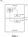
- FIG. 1 is a block diagram of foldable electronic device 100, in accordance with one embodiment.
- the foldable electronic device 100 includes a first lid 102 and a second lid 104.
- a first IMU 106a is implemented in the first lid 102.
- a second IMU 106b is implemented in the second lid 104.
- the foldable electronic device 100 includes a sensor processing unit 108. As will be set forth in more detail below, the components of the foldable electronic device 100 cooperate to generate sensor data with improved accuracy.
- the first lid 102 and the second lid 104 of the foldable electronic device 100 enable folding and unfolding of the electronic device 100. More particularly, the top lid 102 and the bottom lid 104 are coupled to a hinge 113.
- the hinge 113 enables the top lid 102 and the bottom lid 104 to be rotated relative to each other. When the rotation angle between the top lid 102 and the bottom lid 104 is 0°, the first lid 102 and the second lid 104 are pressed together. As the rotation angle increases from 0°, the first lid 102 and the second lid 104 are rotated away from each other.
- the foldable electronic device 100 includes a display implemented on one or both of the first lid 102 and the second lid 104.
- the rotation angle is 0° and the first lid 102 and the second lid 104 are pressed together, the display is inaccessible to a user.
- the user opens the foldable electronic device by rotating the first lid 102 and the second lid 104 away from each other to provide access to the display. This also provides access to inputs such as a keyboard or touchscreen implemented on one or both of the first lid 102 and the second lid 104.
- the foldable electronic device 100 includes various software applications that utilize inertial sensor data from the IMUs 106.
- software applications can include map applications that track the orientation or traveling direction of the foldable electronic device 100, games that track the orientation or motion of the foldable electronic device 100, fall detection applications, and many other types of applications.
- the accuracy of such applications depends, in part, on the accuracy of the sensor data from the IMUs 106.
- the IMUs 106 each include one or more inertial sensors.
- each IMU 106 includes a three-axis accelerometer and a three-axis gyroscope.
- the accelerometer senses acceleration in each of the three axes and generates sensor signals indicative of accelerations on each axis.
- the gyroscope senses angular velocity around each of the three axes and generates sensor signals indicative of the angular velocities on each axis.
- Each IMU 106 can include digital processing circuitry.
- the inertial sensors initially generates analog sensor signals indicative of the accelerations or angular velocities.
- the digital processing circuitry of each IMU receives the analog sensor signals and processes the analog sensor signals to generate digital sensor data.
- each IMU 106 can include one or more analog-to-digital converters (ADC) to convert the analog signals to digital signals.
- ADC analog-to-digital converters
- Each IMU 106 can include additional signal processing circuitry to process or otherwise condition the sensor data for further analysis, as will be described in more detail below.
- each IMU 106 includes one or more inertial sensors and an application specific integrated circuit (ASIC).
- the inertial sensors and the ASIC are on separate integrated circuit dies.
- the inertial sensors and the ASIC are implemented on a single system on chip integrated circuit die.
- Each IMU 106 can include additional components or circuitry without departing from the scope of the present disclosure.
- the foldable electronic device 100 includes a sensor processing unit 108.
- the sensor processing unit 108 is coupled to the first IMU 106a and the second IMU 106b.
- the sensor processing unit 108 receives first sensor data from the IMU 106a and second sensor data from the IMU 106b.
- Each set of sensor data can include accelerometer and gyroscope data as described above.
- the sensor processing unit 108 is shown as separate from the IMU 106a and the IMU 106b, in practice, the sensor processing unit 108 can be part of either the first IMU 106a or the second IMU 106b.
- the sensor processing unit 108 receives the first and second sensor data from the IMUs 106a and 106b and generates combined sensor data.
- the combined sensor data is more accurate than either the first sensor data or the second sensor data.
- the sensor processing unit 108 can then provide the combined sensor data to other components or applications of the foldable electronic device 100. The other applications or components can then utilize the combined sensor data to more effectively or accurately perform their functions.
- Another possible solution to generate the combined sensor data is to perform a weighted average according to the maximal ratio combining technique.
- a weighting value ⁇ 2 2 based on the noise level of the second sensor data is applied to the first sensor data s1 and a weighting value ⁇ 1 2 based on the noise level of the first sensor data is applied to the second sensor data s2.
- Generating the combined sensor data with a weighted average can provide improved accuracy (less noise) than both the first sensor data and the second sensor data even when the first and second sensor data have differing noise levels.
- the drawback of the weighted average is that the noise level of each IMU 106 may need to be known beforehand. Accordingly, it is beneficial to ascertain the noise values in the factory.
- the sensor processing unit 108 of Figure 1 utilizes a solution in which accurate combined sensor data is generated based, in part, on the rotation angle between the first lid 102 and the second lid 104.
- the sensor processing unit 108 detects the rotation angle between the first lid 102 and the second lid 104.
- the sensor processing unit 108 then generates rotated second sensor data by adjusting the second sensor data based on the rotation angle.
- the sensor processing unit 108 then generates combined sensor data by combining the first sensor data with the rotated second sensor data.
- the combined sensor data can be generated by performing a simple average, a weighted average, or another type of combination of the first sensor data and the rotated second sensor data. The result is highly accurate combined sensor data. Further details regarding the generation of the rotated second sensor data and the combined sensor data is provided in relation to Figure 2 .
- first IMU 106a and the second IMU 106b it is beneficial for the first IMU 106a and the second IMU 106b to be relatively close to the hinge 113. Furthermore, it is beneficial for the first IMU 106a and the second IMU 106b to be at a same distance from the hinge 113. Accordingly, in one embodiment, the first IMU 106a and the second IMU 106b are at a same distance from the hinge 113. This can help increase the accuracy of the combined sensor data.
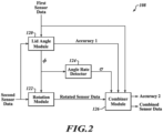
- FIG. 2 is a functional diagram of a sensor processing unit 108, in accordance with one embodiment.
- the sensor processing unit 108 of Figure 2 is one example of the sensor processing unit 108 of Figure 1 .
- the sensor processing unit 108 includes a lid angle module 120.
- Lid angle module 120 receives the first sensor data from the IMU 106a and the second sensor data from the IMU 106b.
- the lid angle module 120 calculates the rotation angle ⁇ based on the first sensor data and the second sensor data.
- the rotation angle ⁇ corresponds to the angle between the first lid 102 and the second lid 104.
- the lid angle module 120 also calculates a first accuracy value based on the first sensor data and the second sensor data.
- the lid angle module 120 can include circuitry, memory, software instructions, and other resources for calculating, measuring, or looking up the rotation angle ⁇ and calculating the first accuracy based on the first sensor data and the second sensor data.
- the sensor processing unit 108 includes a rotation module 122.
- the rotation module 120 is coupled to the lid angle module 120.
- the rotation module 120 receives the second sensor data from the IMU 106b and the rotation angle ⁇ from the lid angle module 120.
- the rotation module 122 generates rotated second sensor data from the second sensor data by adjusting the second sensor data based on the rotation angle ⁇ .
- the rotation module 122 generates the rotated second sensor data by aligning the second sensor data with the first sensor data. Accordingly, the rotation module 122 can apply a rotation to each axis of the second sensor data based on the rotation angle ⁇ in order to generate the rotated second sensor data.
- applying the rotation matrix R to the second sensor data corresponds to multiplying each sample of the sensor data by the rotation matrix R.
- each sample of the second sensor data will include a vector including an acceleration value for each of the three axes of the accelerometer of the second IMU 106b.
- Each sample of the second sensor data will also include a vector including an angular velocity value for each of the three axes of the gyroscope of the second IMU 106b. Both the acceleration vector and the angular velocity vector are multiplied by the rotation matrix R in order to generate the rotated second sensor data.
- each sample of the rotated second sensor data includes a rotated accelerometer vector and a rotated gyroscope vector.
- the combiner module 126 receives the rotated second sensor data and the first sensor data.
- the combiner module 126 generates combined sensor data by combining the first sensor data with the rotated second sensor data.
- the combiner module 126 can generate the combined sensor data based on a simple average of the first sensor data and the rotated second sensor data as described previously, a weighted average (according to the maximal ratio combining technique) of the first sensor data and the rotated second sensor data as described previously, or another suitable manner.
- the combiner module 126 can include processing resources, memory resources, software resources to generate the combined sensor data.
- the combiner module 126 generates a second accuracy value.
- the second accuracy value corresponds to an overall accuracy of the combined sensor data.
- the second accuracy value can be generated based on the first accuracy value describing the accuracy of the angle of rotation.
- the combiner module 126 receives the first accuracy value from the lid angle module 120.
- the combiner module 126 compares the first accuracy value to a threshold value. If the first accuracy value is lower than the threshold value, then the combiner module 126 does not combine the first sensor data with the rotated second sensor data. Instead, the combiner module 126 outputs the first sensor data and/or the rotated second sensor data rather than combined sensor data. Accordingly, if the first accuracy value is lower than the threshold value, the combiner module 126 stops generating combined sensor data. If the first accuracy value is greater than or equal to the threshold value, then the combiner module 126 generates the combined sensor data as described above.
- Accelerometer sensitivity and offset calibration can be executed at runtime via 6-points tumble calibration or 9-points calibration, or the like.
- Gyroscope sensitivity calibration can be implemented in factory.
- Gyroscope offset calibration can be implemented at runtime (e.g., when the device is detected being steady, the gyroscope offset is computed).
- Sensor synchronization plays a key role while moving the device in order to minimize the difference in the sampling time.
- Two IMUs can be synchronized providing an external synchronization signal as input (e.g., STMicroelectronics IMUs ODR-triggered mode or Data Enable mode).
- Sensor placement plays a role while moving the device in order to minimize the difference in the sensed physical quantity. Accordingly, it is beneficial to place the sensors as close to each other as possible and symmetrical with respect to the hinge 113 of the device.
- the sensor processing unit 108 includes an angle rate detector 124.
- the angular rate detector 124 receives the rotation angle ⁇ from the lid angle module 120.
- the angular rate detector 124 detects the rate of change of the rotation angle ⁇ and generates an angle change value ⁇ indicating the rate of change of the rotation angle ⁇ .
- Knowing the rate of change of the rotation angle ⁇ can be beneficial to the combiner module 126. This is because if the angle ⁇ is changing rapidly, then the accuracy of the combined acceleration data may be compromised. This occurs for example, when a user is rapidly opening or closing the foldable electronic device. In the moment of this opening or closing, the combined sensor data may not be accurate.
- the angle change value can be calculated based on a standard deviation, a variance, or an approximation of either of these quantities.
- the combiner module 126 receives the angle change value ⁇ from the angle rate detector 124.
- the combiner module 126 compares the angle change value ⁇ to a threshold value. If the angle change value ⁇ is greater than or equal to the threshold value, then the combiner module 126 does not combine the first sensor data with the rotated second sensor data. Instead, the combiner module 126 outputs the first sensor data and/or the rotated second sensor data rather than combined sensor data. Accordingly, if the angle change value ⁇ is greater than or equal to the threshold value, the combiner module 126 stops generating combined sensor data. If the angle change value ⁇ is less than the threshold value, then the combiner module 126 generates the combined sensor data as described above.
- FIG 3 is a block diagram of a foldable electronic device 100, in accordance with one embodiment.
- the foldable electronic device 100 of Figure 3 is one example of a foldable electronic device of Figure 1 .
- Figure 3 does not illustrate the first lid 102 and the second lid 104.
- the electronic device 100 includes multiple IMUs 106, as described previously.
- the electronic device 100 includes a sensor processing unit 108, as described previously.
- the sensor processing unit 108 is part of one of the IMUs 106 or is separate from all of the IMUs.
- the foldable electronic device 100 includes a plurality of applications 130.
- the applications 130 may correspond to software applications that utilize processing, memory, and the software resources of the foldable electronic device 100 and that receive the combined sensor data from the sensor processing unit 108.
- the applications 130 can include hardware circuits that receive the combined sensor data from the sensor processing unit 108 and perform a function or generate data based on the combined sensor data. Examples of applications 130 can include games, map applications, orientation applications, fall sensors, collision sensors, driving monitoring applications, or other types of applications. Because the applications 130 utilize the combined sensor data based on the rotation angle ⁇ , the applications 130 can operate more effectively because the combined sensor data is more accurate.
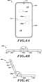
- FIG 4A is a top view of a foldable smartphone 400, in accordance with one embodiment.
- the foldable smartphone 400 is one example of a foldable electronic device 100 of Figure 1 .
- the foldable smartphone 400 includes a first lid 102 and a second lid 104.
- a display 110 is implemented on both the first lid 102 and the second lid 104.
- the display 110 can output images to a user of the full smartphone 400.
- the display 110 can also correspond to a touchscreen.
- a first IMU 106a is implemented in the first lid 102.
- a second IMU 106b is implemented in the second lid 104.
- the sensor processing unit 108 is implemented in the first lid 102, though in practice, the sensor processing unit 108 can be implemented in either the first lid 102 or the second lid 104.
- the foldable smartphone 400 includes a hinge 113.
- the first lid 102 and the second lid 104 can rotate relative to each other around the hinge 113.
- the first lid 102 and the second lid 104 are open with a rotation angle of 180°.
- the first IMU 106a and the second IMU 106b are each positioned at an equal distance from the hinge 113. This can help improve the accuracy of the combined sensor data.
- the first IMU 106a and the second IMU 106b are positioned close to the hinge 113, thereby improving the accuracy of the combined sensor data.
- the foldable smartphone 400 includes a camera 112 implemented in the first lid 102.
- the camera 112 can include a plurality of image sensors including visible light sensors, infrared light sensors, ultraviolet light sensors, or other types of sensors.
- Figure 4B is a side view of the foldable smart-phone 400 of Figure 4A .
- the first lid 102 and the second lid 104 have a rotation angle ⁇ of 180°. In some embodiments, this corresponds to a maximum rotation angle ⁇ .
- Figure 4C is a side view of the foldable smart-phone 400 of Figure 4A , with an intermediate rotation angle ⁇ .
- a user of the foldable smart-phone can rotate the first lid 102 and the second lid 104 to any rotation angle between 0° and 180°.
- the sensor processing unit is configured to generate the combined sensor data if the angle change value is less than a threshold value and stop generation of the combined sensor data if the angle change value is greater than or equal to the threshold value.
- the combiner circuit is configured to generate an accuracy value of the combined sensor data.
Landscapes
- Engineering & Computer Science (AREA)
- Computer Hardware Design (AREA)
- Theoretical Computer Science (AREA)
- Physics & Mathematics (AREA)
- General Physics & Mathematics (AREA)
- Human Computer Interaction (AREA)
- General Engineering & Computer Science (AREA)
- Signal Processing (AREA)
- Mathematical Physics (AREA)
- Radar, Positioning & Navigation (AREA)
- Remote Sensing (AREA)
- Gyroscopes (AREA)
- Telephone Function (AREA)
Abstract
Description
- The present invention relates to foldable electronic devices, and, more particularly, to processing sensor data in foldable electronic devices.
- Foldable electronic devices typically include a top lid and a bottom lid. Two examples of foldable electronic devices are laptop computers and foldable smartphones. In the example of foldable smartphones, a screen may be implemented across both the top lid and the bottom lid. A camera or other types of image sensors may be implemented in the top lid. In a laptop computer, a keyboard is typically implemented in the bottom lid. A display is typically mounted in the top lid.
- In some cases, sensors may be implemented in both the bottom lid and the top lid of foldable electronic devices. However, there may be various challenges associated with processing signals from the multiple sensors. It would be beneficial to improve the processing of signals in foldable electronic devices.
- All of the subject matter discussed in the Background section is not necessarily prior art and should not be assumed to be prior art merely as a result of its discussion in the Background section. Along these lines, any recognition of problems in the prior art discussed in the Background section or associated with such subject matter should not be treated as prior art unless expressly stated to be prior art. Instead, the discussion of any subject matter in the Background section should be treated as part of the inventor's approach to the particular problem, which, in and of itself, may also be inventive.
- The invention is set out in the annexed claims.
- Embodiments of the present disclosure provide improved utilization of sensor data from multiple inertial measurement units (IMUs) in a foldable electronic device. A foldable electronic device includes a first lid and a second lid rotatably coupled together via a hinge. A first IMU is implemented in the first lid and generates first sensor data. A second IMU is implemented in the second lid and generates second sensor data. As a user utilizes the foldable electronic device, the angle of rotation between the first lid and the second lid may vary. Embodiments of the present disclosure detect the angle of rotation between the first and second lids and then apply a rotation matrix to the second sensor data to generate rotated second sensor data. Embodiments of the present disclosure combine the first sensor data with the rotated second sensor data in order to generate combined sensor data. The combined sensor data has a greater accuracy than either of the first or second sensor data.
- In one embodiment, a method includes generating first sensor data with a first inertial measurement unit in a first lid of a foldable electronic device, generating second sensor data with a second inertial measurement unit in a second lid of the foldable electronic device, and detecting a rotation angle between the first lid and the second lid based on the first and second sensor data. The method includes generating rotated second sensor data by adjusting the second sensor data based on the rotation angle and generating combined sensor data by combining the first sensor data and the rotated second sensor data.
- In one embodiment, an electronic device includes a first lid including a first inertial measurement unit configured to generate first inertial sensor data and a second lid including a second inertial measurement unit configured to generate second inertial sensor data. The electronic device includes a sensor processing unit configured to detect a rotation angle between the first lid and the second lid based on the first sensor data and the second sensor data, generate rotated second sensor data by adjusting the second sensor data based on the rotation angle, and generate combined sensor data by combining the first sensor data and the rotated second sensor data.
- In one embodiment, a foldable smartphone includes a first lid including a first inertial measurement unit configured to generate first inertial sensor data, a hinge coupled to the first lid, and a second lid rotatably coupled to the first lid by the hinge and including a second inertial measurement unit configured to generate second inertial sensor data. The foldable smartphone includes a sensor processing unit including a lid angle module configured to detect an angle of rotation between the first and second lids based on the first and second sensor data, a rotation module configured to generate rotated second sensor data by adjusting the second sensor data based on the angle of rotation, and a combiner module configured to generate combined sensor data from the first sensor data and the rotated second sensor data.
-
-
Figure 1 is a block diagram of a foldable electronic device including multiple IMUs, in accordance with one embodiment. -
Figure 2 is a functional diagram of a sensor processing unit of a foldable electronic device, in accordance with one embodiment. -
Figure 3 is a schematic diagram of a foldable electronic device, in accordance with one embodiment. -
Figures 4A-4C are various views of a foldable smartphone including multiple IMUs, in accordance with one embodiment. -
Figures 5A-5B are various views of a laptop computer including multiple IMUs, in accordance with one embodiment. -
Figure 6 is a flow diagram of a method for operating a foldable electronic device, in accordance with one embodiment. - In the following description, certain specific details are set forth in order to provide a thorough understanding of various disclosed embodiments. However, one skilled in the relevant art will recognize that embodiments may be practiced without one or more of these specific details, or with other methods, components, materials, etc. In other instances, well-known systems, components, and circuitry associated with integrated circuits have not been shown or described in detail, to avoid unnecessarily obscuring descriptions of the embodiments.
- Unless the context requires otherwise, throughout the specification and claims which follow, the word "comprise" and variations thereof, such as, "comprises" and "comprising" are to be construed in an open, inclusive sense, that is as "including, but not limited to." Further, the terms "first," "second," and similar indicators of sequence are to be construed as interchangeable unless the context clearly dictates otherwise.
- Reference throughout this specification to "one embodiment" or "an embodiment" means that a particular feature, structure, or characteristic described in connection with the embodiment is included in at least one embodiment. Thus, the appearances of the phrases "in one embodiment" or "in an embodiment" in various places throughout this specification are not necessarily all referring to the same embodiment. Furthermore, the particular features, structures, or characteristics can be combined in any suitable manner in one or more embodiments.
- As used in this specification and the appended claims, the singular forms "a," "an," and "the" include plural referents unless the content clearly dictates otherwise. It should also be noted that the term "or" is generally employed in its broadest sense, that is as meaning "and/or" unless the content clearly dictates otherwise.
-
Figure 1 is a block diagram of foldableelectronic device 100, in accordance with one embodiment. The foldableelectronic device 100 includes afirst lid 102 and asecond lid 104. A first IMU 106a is implemented in thefirst lid 102. A second IMU 106b is implemented in thesecond lid 104. The foldableelectronic device 100 includes asensor processing unit 108. As will be set forth in more detail below, the components of the foldableelectronic device 100 cooperate to generate sensor data with improved accuracy. - The
first lid 102 and thesecond lid 104 of the foldableelectronic device 100 enable folding and unfolding of theelectronic device 100. More particularly, thetop lid 102 and thebottom lid 104 are coupled to ahinge 113. Thehinge 113 enables thetop lid 102 and thebottom lid 104 to be rotated relative to each other. When the rotation angle between thetop lid 102 and thebottom lid 104 is 0°, thefirst lid 102 and thesecond lid 104 are pressed together. As the rotation angle increases from 0°, thefirst lid 102 and thesecond lid 104 are rotated away from each other. - Though not shown in
Figure 1 , the foldableelectronic device 100 includes a display implemented on one or both of thefirst lid 102 and thesecond lid 104. When the rotation angle is 0° and thefirst lid 102 and thesecond lid 104 are pressed together, the display is inaccessible to a user. The user opens the foldable electronic device by rotating thefirst lid 102 and thesecond lid 104 away from each other to provide access to the display. This also provides access to inputs such as a keyboard or touchscreen implemented on one or both of thefirst lid 102 and thesecond lid 104. - The foldable
electronic device 100 includes various software applications that utilize inertial sensor data from the IMUs 106. Examples of such software applications can include map applications that track the orientation or traveling direction of the foldableelectronic device 100, games that track the orientation or motion of the foldableelectronic device 100, fall detection applications, and many other types of applications. The accuracy of such applications depends, in part, on the accuracy of the sensor data from the IMUs 106. - The IMUs 106 each include one or more inertial sensors. In one embodiment, each IMU 106 includes a three-axis accelerometer and a three-axis gyroscope. The accelerometer senses acceleration in each of the three axes and generates sensor signals indicative of accelerations on each axis. The gyroscope senses angular velocity around each of the three axes and generates sensor signals indicative of the angular velocities on each axis.
- Each IMU 106 can include digital processing circuitry. In particular, the inertial sensors initially generates analog sensor signals indicative of the accelerations or angular velocities. The digital processing circuitry of each IMU receives the analog sensor signals and processes the analog sensor signals to generate digital sensor data. Accordingly, each IMU 106 can include one or more analog-to-digital converters (ADC) to convert the analog signals to digital signals. Each IMU 106 can include additional signal processing circuitry to process or otherwise condition the sensor data for further analysis, as will be described in more detail below. In one embodiment, each IMU 106 includes one or more inertial sensors and an application specific integrated circuit (ASIC). In one embodiment, the inertial sensors and the ASIC are on separate integrated circuit dies. Alternatively, the inertial sensors and the ASIC are implemented on a single system on chip integrated circuit die. Each IMU 106 can include additional components or circuitry without departing from the scope of the present disclosure.
- The foldable
electronic device 100 includes asensor processing unit 108. Thesensor processing unit 108 is coupled to thefirst IMU 106a and thesecond IMU 106b. Thesensor processing unit 108 receives first sensor data from theIMU 106a and second sensor data from theIMU 106b. Each set of sensor data can include accelerometer and gyroscope data as described above. Although thesensor processing unit 108 is shown as separate from theIMU 106a and theIMU 106b, in practice, thesensor processing unit 108 can be part of either thefirst IMU 106a or thesecond IMU 106b. - The
sensor processing unit 108 receives the first and second sensor data from theIMUs sensor processing unit 108 can then provide the combined sensor data to other components or applications of the foldableelectronic device 100. The other applications or components can then utilize the combined sensor data to more effectively or accurately perform their functions. - One possible solution to generate the combined sensor data is to perform a simple averaging of the first sensor data and the second sensor data. If s1 represents the first sensor data, s2 represents the second sensor data, and sc represents the combined sensor data, then the combined sensor data sc can be generated by performing a simple averaging of the first and second sensor data in the following manner:

- If the noise level of the first sensor data s1, measured by the standard deviation σ 1, is approximately the same as the noise level of the second sensor data s2, measured by the standard deviation σ 2, then the noise level of the combined sensor data will be less than the noise level of both the first and second sensor data, as set forth in the following relationship:

- Another possible solution to generate the combined sensor data is to perform a weighted average according to the maximal ratio combining technique. In this case, a
weighting value 
weighting value 

- Generating the combined sensor data with a weighted average can provide improved accuracy (less noise) than both the first sensor data and the second sensor data even when the first and second sensor data have differing noise levels. The overall noise of the combined sensor data from the weighted average is given by the following relationship:

- However, the drawback of the weighted average is that the noise level of each IMU 106 may need to be known beforehand. Accordingly, it is beneficial to ascertain the noise values in the factory.
- The
sensor processing unit 108 ofFigure 1 , in accordance with principles of the present disclosure, utilizes a solution in which accurate combined sensor data is generated based, in part, on the rotation angle between thefirst lid 102 and thesecond lid 104. Thesensor processing unit 108 detects the rotation angle between thefirst lid 102 and thesecond lid 104. Thesensor processing unit 108 then generates rotated second sensor data by adjusting the second sensor data based on the rotation angle. Thesensor processing unit 108 then generates combined sensor data by combining the first sensor data with the rotated second sensor data. The combined sensor data can be generated by performing a simple average, a weighted average, or another type of combination of the first sensor data and the rotated second sensor data. The result is highly accurate combined sensor data. Further details regarding the generation of the rotated second sensor data and the combined sensor data is provided in relation toFigure 2 . - In one embodiment, it is beneficial for the
first IMU 106a and thesecond IMU 106b to be relatively close to thehinge 113. Furthermore, it is beneficial for thefirst IMU 106a and thesecond IMU 106b to be at a same distance from thehinge 113. Accordingly, in one embodiment, thefirst IMU 106a and thesecond IMU 106b are at a same distance from thehinge 113. This can help increase the accuracy of the combined sensor data. -
Figure 2 is a functional diagram of asensor processing unit 108, in accordance with one embodiment. Thesensor processing unit 108 ofFigure 2 is one example of thesensor processing unit 108 ofFigure 1 . - The
sensor processing unit 108 includes a lid angle module 120. Lid angle module 120 receives the first sensor data from theIMU 106a and the second sensor data from theIMU 106b. The lid angle module 120 calculates the rotation angle ϕ based on the first sensor data and the second sensor data. The rotation angle ϕ corresponds to the angle between thefirst lid 102 and thesecond lid 104. The lid angle module 120 also calculates a first accuracy value based on the first sensor data and the second sensor data. The lid angle module 120 can include circuitry, memory, software instructions, and other resources for calculating, measuring, or looking up the rotation angle ϕ and calculating the first accuracy based on the first sensor data and the second sensor data. - The
sensor processing unit 108 includes a rotation module 122. The rotation module 120 is coupled to the lid angle module 120. The rotation module 120 receives the second sensor data from theIMU 106b and the rotation angle ϕ from the lid angle module 120. The rotation module 122 generates rotated second sensor data from the second sensor data by adjusting the second sensor data based on the rotation angle ϕ. - In one embodiment, the rotation module 122 generates the rotated second sensor data by aligning the second sensor data with the first sensor data. Accordingly, the rotation module 122 can apply a rotation to each axis of the second sensor data based on the rotation angle ϕ in order to generate the rotated second sensor data.
- In one embodiment, the rotation module 122 generates the rotated second sensor data by applying a rotation matrix to the second sensor data. More particularly, the rotation module 122 multiplies the second sensor data by a rotation matrix. The rotation module 122 generates a rotation matrix R based on the rotation angle ϕ. More particularly, the rotation module 122 identifies an angle θ = π - ϕ (or θ = 180° - ϕ) and generates the rotation matrix R based on the angle θ. In one embodiment, the rotation matrix R is given as follows:

- In one embodiment, applying the rotation matrix R to the second sensor data corresponds to multiplying each sample of the sensor data by the rotation matrix R. In an example in which the second sensor data includes the three axes of accelerometer data and three axes of gyroscope data, each sample of the second sensor data will include a vector including an acceleration value for each of the three axes of the accelerometer of the
second IMU 106b. Each sample of the second sensor data will also include a vector including an angular velocity value for each of the three axes of the gyroscope of thesecond IMU 106b. Both the acceleration vector and the angular velocity vector are multiplied by the rotation matrix R in order to generate the rotated second sensor data. Accordingly, each sample of the rotated second sensor data includes a rotated accelerometer vector and a rotated gyroscope vector. - As described previously, applying a rotation matrix R to the second sensor data corresponds to aligning the axes of the
second IMU 106b with the axes of thefirst IMU 106a. The variances utilized for the maximal ratio combining technique, indicative of the noise level of each sensor axis, are the variances of the rotated IMU, which are computed at runtime for every processed sample as follows:



2 , σ y2 and σ z2 correspond to the noise levels associated with the x, y, and z axes of thesecond IMU 106b and have been measured in factory and stored in a memory of thesensor processing unit 108. - The
combiner module 126 receives the rotated second sensor data and the first sensor data. Thecombiner module 126 generates combined sensor data by combining the first sensor data with the rotated second sensor data. Thecombiner module 126 can generate the combined sensor data based on a simple average of the first sensor data and the rotated second sensor data as described previously, a weighted average (according to the maximal ratio combining technique) of the first sensor data and the rotated second sensor data as described previously, or another suitable manner. Thecombiner module 126 can include processing resources, memory resources, software resources to generate the combined sensor data. - In one embodiment, the
combiner module 126 generates a second accuracy value. The second accuracy value corresponds to an overall accuracy of the combined sensor data. The second accuracy value can be generated based on the first accuracy value describing the accuracy of the angle of rotation. In one embodiment, thecombiner module 126 receives the first accuracy value from the lid angle module 120. Thecombiner module 126 compares the first accuracy value to a threshold value. If the first accuracy value is lower than the threshold value, then thecombiner module 126 does not combine the first sensor data with the rotated second sensor data. Instead, thecombiner module 126 outputs the first sensor data and/or the rotated second sensor data rather than combined sensor data. Accordingly, if the first accuracy value is lower than the threshold value, thecombiner module 126 stops generating combined sensor data. If the first accuracy value is greater than or equal to the threshold value, then thecombiner module 126 generates the combined sensor data as described above. - In one embodiment, it is beneficial to implement sensitivity and offset calibration for both accelerometer and gyroscope of each IMU 106. Accelerometer sensitivity and offset calibration can be executed at runtime via 6-points tumble calibration or 9-points calibration, or the like. Gyroscope sensitivity calibration can be implemented in factory. Gyroscope offset calibration can be implemented at runtime (e.g., when the device is detected being steady, the gyroscope offset is computed). Sensor synchronization plays a key role while moving the device in order to minimize the difference in the sampling time. Two IMUs can be synchronized providing an external synchronization signal as input (e.g., STMicroelectronics IMUs ODR-triggered mode or Data Enable mode). Sensor placement plays a role while moving the device in order to minimize the difference in the sensed physical quantity. Accordingly, it is beneficial to place the sensors as close to each other as possible and symmetrical with respect to the
hinge 113 of the device. - In one embodiment, the
sensor processing unit 108 includes anangle rate detector 124. Theangular rate detector 124 receives the rotation angle ϕ from the lid angle module 120. Theangular rate detector 124 detects the rate of change of the rotation angle ϕ and generates an angle change value σ indicating the rate of change of the rotation angle ϕ. - Knowing the rate of change of the rotation angle ϕ can be beneficial to the
combiner module 126. This is because if the angle ϕ is changing rapidly, then the accuracy of the combined acceleration data may be compromised. This occurs for example, when a user is rapidly opening or closing the foldable electronic device. In the moment of this opening or closing, the combined sensor data may not be accurate. The angle change value can be calculated based on a standard deviation, a variance, or an approximation of either of these quantities. - In one embodiment, the
combiner module 126 receives the angle change value σ from theangle rate detector 124. Thecombiner module 126 compares the angle change value σ to a threshold value. If the angle change value σ is greater than or equal to the threshold value, then thecombiner module 126 does not combine the first sensor data with the rotated second sensor data. Instead, thecombiner module 126 outputs the first sensor data and/or the rotated second sensor data rather than combined sensor data. Accordingly, if the angle change value σ is greater than or equal to the threshold value, thecombiner module 126 stops generating combined sensor data. If the angle change value σ is less than the threshold value, then thecombiner module 126 generates the combined sensor data as described above. -
Figure 3 is a block diagram of a foldableelectronic device 100, in accordance with one embodiment. The foldableelectronic device 100 ofFigure 3 is one example of a foldable electronic device ofFigure 1 .Figure 3 does not illustrate thefirst lid 102 and thesecond lid 104. Theelectronic device 100 includes multiple IMUs 106, as described previously. Theelectronic device 100 includes asensor processing unit 108, as described previously. Thesensor processing unit 108 is part of one of the IMUs 106 or is separate from all of the IMUs. - The foldable
electronic device 100 includes a plurality of applications 130. The applications 130 may correspond to software applications that utilize processing, memory, and the software resources of the foldableelectronic device 100 and that receive the combined sensor data from thesensor processing unit 108. Alternatively, the applications 130 can include hardware circuits that receive the combined sensor data from thesensor processing unit 108 and perform a function or generate data based on the combined sensor data. Examples of applications 130 can include games, map applications, orientation applications, fall sensors, collision sensors, driving monitoring applications, or other types of applications. Because the applications 130 utilize the combined sensor data based on the rotation angle ϕ, the applications 130 can operate more effectively because the combined sensor data is more accurate. -
Figure 4A is a top view of afoldable smartphone 400, in accordance with one embodiment. Thefoldable smartphone 400 is one example of a foldableelectronic device 100 ofFigure 1 . Thefoldable smartphone 400 includes afirst lid 102 and asecond lid 104. Adisplay 110 is implemented on both thefirst lid 102 and thesecond lid 104. Thedisplay 110 can output images to a user of thefull smartphone 400. Thedisplay 110 can also correspond to a touchscreen. Afirst IMU 106a is implemented in thefirst lid 102. Asecond IMU 106b is implemented in thesecond lid 104. Thesensor processing unit 108 is implemented in thefirst lid 102, though in practice, thesensor processing unit 108 can be implemented in either thefirst lid 102 or thesecond lid 104. - The
foldable smartphone 400 includes ahinge 113. Thefirst lid 102 and thesecond lid 104 can rotate relative to each other around thehinge 113. In the view ofFigure 4A , thefirst lid 102 and thesecond lid 104 are open with a rotation angle of 180°. As can be seen inFigure 4A , thefirst IMU 106a and thesecond IMU 106b are each positioned at an equal distance from thehinge 113. This can help improve the accuracy of the combined sensor data. Furthermore, thefirst IMU 106a and thesecond IMU 106b are positioned close to thehinge 113, thereby improving the accuracy of the combined sensor data. - The
foldable smartphone 400 includes acamera 112 implemented in thefirst lid 102. Thecamera 112 can include a plurality of image sensors including visible light sensors, infrared light sensors, ultraviolet light sensors, or other types of sensors. -
Figure 4B is a side view of the foldable smart-phone 400 ofFigure 4A . InFigure 4B , thefirst lid 102 and thesecond lid 104 have a rotation angle ϕ of 180°. In some embodiments, this corresponds to a maximum rotation angle ϕ. -
Figure 4C is a side view of the foldable smart-phone 400 ofFigure 4A , with an intermediate rotation angle ϕ. A user of the foldable smart-phone can rotate thefirst lid 102 and thesecond lid 104 to any rotation angle between 0° and 180°. -
Figure 5A is a perspective view of alaptop computer 500, in accordance with one embodiment. Thelaptop computer 500 ofFigure 5A is one example of a foldableelectronic device 100 ofFigure 1 . Thelaptop computer 500 includes afirst lid 102 and asecond lid 104. Adisplay 110 is implemented on afirst lid 102. Akeyboard 115 is implemented on thesecond lid 104. Afirst IMU 106a is implemented in thefirst lid 102. Asecond IMU 106b is implemented in thesecond lid 104. Thesensor processing unit 108 is implemented in thefirst lid 102, though in practice, thesensor processing unit 108 can be implemented in either thefirst lid 102 or thesecond lid 104. - The
laptop computer 500 includes ahinge 113. Thefirst lid 102 and thesecond lid 104 can rotate relative to each other around thehinge 113. As can be seen inFigure 5A , thefirst IMU 106a and thesecond IMU 106b are each positioned at an equal distance from thehinge 113. This can help improve the accuracy of the combined sensor data. Furthermore, thefirst IMU 106a and thesecond IMU 106b are positioned close to thehinge 113, thereby improving the accuracy of the combined sensor data. - The
laptop computer 500 includes acamera 112 implemented in thefirst lid 102. Thecamera 112 can include a plurality of image sensors including visible light sensors, infrared light sensors, ultraviolet light sensors, or other types of sensors. -
Figure 5B is a side view of thelaptop computer 500 ofFigure 5A , with an intermediate rotation angle ϕ. A user of thelaptop computer 500 can rotate thefirst lid 102 and thesecond lid 104 to any rotation angle between 0° and a maximum rotation angle based on the design of thelaptop computer 500. Principles of the present disclosure extend to a tablet with a detachable keyboard. In one embodiment, the tablet corresponds to thefirst lid 102 and includes thefirst IMU 106a and thesensor processing unit 108. The detachable keyboard can correspond to thesecond lid 104 and can include thesecond IMU 106b. The tablet and the detachable keyboard can rotate with respect to each other, as described previously. -
Figure 6 is a flow diagram of amethod 600 for operating a foldable electronic device, in accordance with one embodiment. Themethod 600 can utilize processes, systems, and components described in relation toFigures 1-5 . At 602, themethod 600 includes generating first sensor data with a first inertial measurement unit in a first lid of a foldable electronic device. At 604, themethod 600 includes generating second sensor data with a second inertial measurement unit in a second lid of the foldable electronic device. At 606, themethod 600 includes detecting a rotation angle between the first lid and the second lid based on the first and second sensor data. At 608, themethod 600 includes generating rotated second sensor data by adjusting the second sensor data based on the rotation angle. At 610, themethod 600 includes generating combined sensor data by combining the first sensor data and the rotated second sensor data. - In one embodiment, a method includes generating first sensor data with a first inertial measurement unit in a first lid of a foldable electronic device, generating second sensor data with a second inertial measurement unit in a second lid of the foldable electronic device, and detecting a rotation angle between the first lid and the second lid based on the first and second sensor data. The method includes generating rotated second sensor data by adjusting the second sensor data based on the rotation angle and generating combined sensor data by combining the first sensor data and the rotated second sensor data.
- In one embodiment, the adjusting the second sensor data includes applying to the second sensor data a rotation matrix based on the rotation angle.
- In one embodiment, the method includes generating a first accuracy value based on the first and second sensor data and generating the combined sensor data based on the first accuracy value.
- In one embodiment, the method includes generating an angle change value indicating how fast the rotation angle is changing.
- In one embodiment, the method includes generating the combined sensor data if the angle change value is less than a threshold value and stopping generation of the combined sensor data if the angle change value is greater than or equal to the threshold value.
- In one embodiment, the method includes generating a second accuracy value for the combined sensor based on the angle change value.
- In one embodiment, the first sensor data includes first accelerometer data and first gyroscope data, while the second sensor data includes second accelerometer data and second gyroscope data.
- In one embodiment, the combined sensor data includes combined accelerometer data and combined gyroscope data.
- In one embodiment, generating combined sensor data includes averaging the first sensor data and the rotated second sensor data.
- In one embodiment, generating combined sensor data includes applying a first weight to the first sensor data based on a noise level of the rotated second sensor data, applying a second weight to the rotated second sensor data based on a noise level of the first sensor data, and generating a weighted average of the first sensor data and the rotated second sensor data based on the first weight and the second weight.
- In one embodiment, an electronic device includes a first lid including a first inertial measurement unit configured to generate first inertial sensor data and a second lid including a second inertial measurement unit configured to generate second inertial sensor data. The electronic device includes a sensor processing unit configured to detect a rotation angle between the first lid and the second lid based on the first sensor data and the second sensor data, generate rotated second sensor data by adjusting the second sensor data based on the rotation angle, and generate combined sensor data by combining the first sensor data and the rotated second sensor data.
- In one embodiment, the electronic device includes a hinge rotatably coupling the first lid to the second lid.
- In one embodiment, the sensor processing unit is configured to generate an accuracy value based on the first and second sensor data and generate the combined sensor data based on the first accuracy value.
- In one embodiment, the sensor processing unit is configured to generate an angle change value indicating how fast the rotation angle is changing.
- In one embodiment, the sensor processing unit is configured to generate the combined sensor data if the angle change value is less than a threshold value and stop generation of the combined sensor data if the angle change value is greater than or equal to the threshold value.
- In one embodiment, the second sensor data includes applying to the second sensor data a rotation matrix based on the rotation angle.
- In one embodiment, a foldable smartphone includes a first lid including a first inertial measurement unit configured to generate first inertial sensor data, a hinge coupled to the first lid, and a second lid rotatably coupled to the first lid by the hinge and including a second inertial measurement unit configured to generate second inertial sensor data. The foldable smartphone includes a sensor processing unit including a lid angle module configured to detect an angle of rotation between the first and second lids based on the first and second sensor data, a rotation module configured to generate rotated second sensor data by adjusting the second sensor data based on the angle of rotation, and a combiner module configured to generate combined sensor data from the first sensor data and the rotated second sensor data.
- In one embodiment, the sensor processing unit includes angle variation detector configured to generate an angle change value indicating a rate of change of the angle of rotation.
- In one embodiment, the combiner module is configured to receive the angle change value and to generate the combined sensor data based on the angle change value.
- In one embodiment, the combiner circuit is configured to generate an accuracy value of the combined sensor data.
- The various embodiments described above can be combined to provide further embodiments.
Claims (15)
- A method, comprising:generating (602) first sensor data with a first inertial measurement unit in a first lid of a foldable electronic device;generating (604) second sensor data with a second inertial measurement unit in a second lid of the foldable electronic device;detecting (606) a rotation angle (ϕ) between the first lid and the second lid based on the first and second sensor data;generating (608) rotated second sensor data by adjusting the second sensor data based on the rotation angle; andgenerating (610) combined sensor data by combining the first sensor data and the rotated second sensor data.
- The method of claim 1, wherein adjusting the second sensor data includes applying to the second sensor data a rotation matrix based on the rotation angle.
- The method of claim 1 or 2, comprising:generating a first accuracy value (120, Accuracy 1) based on the first and second sensor data; andgenerating the combined sensor data (126) based on the first accuracy value.
- The method of claim 3, comprising generating an angle change value (ϕ) indicating how fast the rotation angle (ϕ) is changing.
- The method of claim 4, comprising:generating the combined sensor data if the angle change value is less than a threshold value; andstopping generation of the combined sensor data if the angle change value is greater than or equal to the threshold value.
- The method of claim 3, comprising generating a second accuracy value (126, Accuracy 2) for the combined sensor based on the angle change value.
- The method of anyone of the preceding claims, wherein the first sensor data includes first accelerometer data and first gyroscope data, while the second sensor data includes second accelerometer data and second gyroscope data, and wherein the combined sensor data includes combined accelerometer data and combined gyroscope data.
- The method of anyone of the preceding claims, wherein generating combined sensor data includes averaging the first sensor data and the rotated second sensor data.
- The method of anyone of the preceding claims, wherein generating combined sensor data includes:applying a first weight to the first sensor data based on a noise level of the rotated second sensor data;applying a second weight to the rotated second sensor data based on a noise level of the first sensor data; andgenerating a weighted average of the first sensor data and second sensor data based on the first weight and the second weight.
- An electronic device, comprising:a first lid (102) including a first inertial measurement unit (106a) configured to generate first inertial sensor data;a second lid (104) including a second inertial measurement unit (106b) configured to generate second inertial sensor data;a sensor processing unit (108) configured to:detect (606) a rotation angle (ϕ) between the first lid and the second lid based on the first sensor data and the second sensor data;generate (608) rotated second sensor data by adjusting the second sensor data based on the rotation angle; andgenerate (610) combined sensor data by combining the first sensor data and the rotated second sensor data.
- The electronic device of claim 10, wherein the first lid (102) is rotatably coupled to the second lid (104), in particular by a hinge (113), and wherein the sensor processing unit (108) is configured to generate a first accuracy value (Accuracy 1) based on the first and second sensor data and generate the combined sensor data based on the first accuracy value.
- The electronic device of claim 11, wherein the sensor processing unit (108) is configured to generate an angle change value (σ) indicating how fast the rotation angle (ϕ) is changing.
- The electronic device of claim 12, wherein the sensor processing unit (108) is configured to:generate the combined sensor data if the angle change value (σ) is less than a threshold value; andstop generation of the combined sensor data if the angle change value (σ) is greater than or equal to the threshold value.
- The electronic device of anyone of claims 11-13, wherein adjusting the second sensor data includes applying to the second sensor data a rotation matrix based on the rotation angle.
- A foldable smartphone, comprising an electronic device according to anyone of claims 10-14.
Applications Claiming Priority (1)
| Application Number | Priority Date | Filing Date | Title |
|---|---|---|---|
| US18/391,359 US20250211661A1 (en) | 2023-12-20 | 2023-12-20 | Imu performance boost on foldable devices |
Publications (1)
| Publication Number | Publication Date |
|---|---|
| EP4575391A1 true EP4575391A1 (en) | 2025-06-25 |
Family
ID=93840582
Family Applications (1)
| Application Number | Title | Priority Date | Filing Date |
|---|---|---|---|
| EP24217678.2A Pending EP4575391A1 (en) | 2023-12-20 | 2024-12-05 | Imu performance boost on foldable devices |
Country Status (3)
| Country | Link |
|---|---|
| US (1) | US20250211661A1 (en) |
| EP (1) | EP4575391A1 (en) |
| CN (1) | CN120186246A (en) |
Citations (2)
| Publication number | Priority date | Publication date | Assignee | Title |
|---|---|---|---|---|
| US20230027806A1 (en) * | 2021-07-19 | 2023-01-26 | Invensense, Inc. | Method and system for determining hinge angle |
| EP4283435A1 (en) * | 2022-05-27 | 2023-11-29 | STMicroelectronics S.r.l. | Device and method for lid angle detection |
Family Cites Families (2)
| Publication number | Priority date | Publication date | Assignee | Title |
|---|---|---|---|---|
| IT201700057066A1 (en) * | 2017-05-25 | 2018-11-25 | St Microelectronics Srl | PROCESSING SYSTEM IMPLEMENTING AN ALGORITHM FOR THE MERGER OF DATA FROM INERTIAL SENSORS, AND METHOD |
| EP4014102B1 (en) * | 2019-12-27 | 2026-04-15 | INTEL Corporation | Hinge angle detection |
-
2023
- 2023-12-20 US US18/391,359 patent/US20250211661A1/en active Pending
-
2024
- 2024-12-05 EP EP24217678.2A patent/EP4575391A1/en active Pending
- 2024-12-18 CN CN202411866518.3A patent/CN120186246A/en active Pending
Patent Citations (2)
| Publication number | Priority date | Publication date | Assignee | Title |
|---|---|---|---|---|
| US20230027806A1 (en) * | 2021-07-19 | 2023-01-26 | Invensense, Inc. | Method and system for determining hinge angle |
| EP4283435A1 (en) * | 2022-05-27 | 2023-11-29 | STMicroelectronics S.r.l. | Device and method for lid angle detection |
Also Published As
| Publication number | Publication date |
|---|---|
| US20250211661A1 (en) | 2025-06-26 |
| CN120186246A (en) | 2025-06-20 |
Similar Documents
| Publication | Publication Date | Title |
|---|---|---|
| US9995575B2 (en) | System and method for improving orientation data | |
| US10309983B2 (en) | Systems and methods for motion detection | |
| US9465044B2 (en) | Angular velocity estimation using a magnetometer and accelerometer | |
| US9140802B2 (en) | Auxiliary as vehicle speed when difference between auxiliary and propagation above threshold | |
| CN101711364A (en) | Force sensing apparatus and method for determining radius of rotation of moving object | |
| CN102165395A (en) | Hand held pointing device with roll compensation | |
| US8655620B2 (en) | Method and module for measuring rotation and portable apparatus comprising the module | |
| US20210270635A1 (en) | Information processing apparatus, information processing method, and program | |
| US20250181120A1 (en) | Lid angle detection | |
| US20250035669A1 (en) | Lid angle detection | |
| Velázquez et al. | A new algorithm for fault tolerance in redundant sensor systems based on real-time variance estimation | |
| US20240085960A1 (en) | Lid angle detection | |
| US12422259B2 (en) | System and method for time synchronized fusion of multiple inertial sensors | |
| US20250211661A1 (en) | Imu performance boost on foldable devices | |
| CN107063181A (en) | The measuring method and device of the level inclination of Multifunctional adjustment table under complex environment | |
| US12487642B2 (en) | Method and system for determining hinge angle | |
| US12436624B2 (en) | Dynamic gravity vector estimation for memory constrained devices | |
| US11590398B2 (en) | Swing analysis method and swing analysis device | |
| US7426878B2 (en) | Sensing device for measuring movement along linear/arc path | |
| EP4687003A1 (en) | Lid angle detection | |
| JP2000283788A (en) | N-multiplexed inertial navigation system | |
| JP3595824B2 (en) | Air data processing device | |
| CN117128917A (en) | Cover angle detection | |
| CN121185336A (en) | An adaptive calibration method and system for gyroscope angle data | |
| JPH09257487A (en) | Apparatus for correcting sensitivity coefficient of gyro sensor |
Legal Events
| Date | Code | Title | Description |
|---|---|---|---|
| PUAI | Public reference made under article 153(3) epc to a published international application that has entered the european phase |
Free format text: ORIGINAL CODE: 0009012 |
|
| STAA | Information on the status of an ep patent application or granted ep patent |
Free format text: STATUS: THE APPLICATION HAS BEEN PUBLISHED |
|
| STAA | Information on the status of an ep patent application or granted ep patent |
Free format text: STATUS: REQUEST FOR EXAMINATION WAS MADE |
|
| AK | Designated contracting states |
Kind code of ref document: A1 Designated state(s): AL AT BE BG CH CY CZ DE DK EE ES FI FR GB GR HR HU IE IS IT LI LT LU LV MC ME MK MT NL NO PL PT RO RS SE SI SK SM TR |
|
| 17P | Request for examination filed |
Effective date: 20250605 |
|
| GRAP | Despatch of communication of intention to grant a patent |
Free format text: ORIGINAL CODE: EPIDOSNIGR1 |
|
| STAA | Information on the status of an ep patent application or granted ep patent |
Free format text: STATUS: GRANT OF PATENT IS INTENDED |