EP4575378A1 - Heat exchanger - Google Patents
Heat exchanger Download PDFInfo
- Publication number
- EP4575378A1 EP4575378A1 EP23854076.9A EP23854076A EP4575378A1 EP 4575378 A1 EP4575378 A1 EP 4575378A1 EP 23854076 A EP23854076 A EP 23854076A EP 4575378 A1 EP4575378 A1 EP 4575378A1
- Authority
- EP
- European Patent Office
- Prior art keywords
- inlet manifold
- tube
- inlet
- heat exchange
- heat exchanger
- Prior art date
- Legal status (The legal status is an assumption and is not a legal conclusion. Google has not performed a legal analysis and makes no representation as to the accuracy of the status listed.)
- Withdrawn
Links
Images




Classifications
-
- F—MECHANICAL ENGINEERING; LIGHTING; HEATING; WEAPONS; BLASTING
- F28—HEAT EXCHANGE IN GENERAL
- F28D—HEAT-EXCHANGE APPARATUS, NOT PROVIDED FOR IN ANOTHER SUBCLASS, IN WHICH THE HEAT-EXCHANGE MEDIA DO NOT COME INTO DIRECT CONTACT
- F28D7/00—Heat-exchange apparatus having stationary tubular conduit assemblies for both heat-exchange media, the media being in contact with different sides of a conduit wall
- F28D7/16—Heat-exchange apparatus having stationary tubular conduit assemblies for both heat-exchange media, the media being in contact with different sides of a conduit wall the conduits being arranged in parallel spaced relation
-
- F—MECHANICAL ENGINEERING; LIGHTING; HEATING; WEAPONS; BLASTING
- F25—REFRIGERATION OR COOLING; COMBINED HEATING AND REFRIGERATION SYSTEMS; HEAT PUMP SYSTEMS; MANUFACTURE OR STORAGE OF ICE; LIQUEFACTION SOLIDIFICATION OF GASES
- F25B—REFRIGERATION MACHINES, PLANTS OR SYSTEMS; COMBINED HEATING AND REFRIGERATION SYSTEMS; HEAT PUMP SYSTEMS
- F25B39/00—Evaporators; Condensers
-
- F—MECHANICAL ENGINEERING; LIGHTING; HEATING; WEAPONS; BLASTING
- F28—HEAT EXCHANGE IN GENERAL
- F28D—HEAT-EXCHANGE APPARATUS, NOT PROVIDED FOR IN ANOTHER SUBCLASS, IN WHICH THE HEAT-EXCHANGE MEDIA DO NOT COME INTO DIRECT CONTACT
- F28D1/00—Heat-exchange apparatus having stationary conduit assemblies for one heat-exchange medium only, the media being in contact with different sides of the conduit wall, in which the other heat-exchange medium is a large body of fluid, e.g. domestic or motor car radiators
- F28D1/02—Heat-exchange apparatus having stationary conduit assemblies for one heat-exchange medium only, the media being in contact with different sides of the conduit wall, in which the other heat-exchange medium is a large body of fluid, e.g. domestic or motor car radiators with heat-exchange conduits immersed in the body of fluid
- F28D1/04—Heat-exchange apparatus having stationary conduit assemblies for one heat-exchange medium only, the media being in contact with different sides of the conduit wall, in which the other heat-exchange medium is a large body of fluid, e.g. domestic or motor car radiators with heat-exchange conduits immersed in the body of fluid with tubular conduits
- F28D1/053—Heat-exchange apparatus having stationary conduit assemblies for one heat-exchange medium only, the media being in contact with different sides of the conduit wall, in which the other heat-exchange medium is a large body of fluid, e.g. domestic or motor car radiators with heat-exchange conduits immersed in the body of fluid with tubular conduits the conduits being straight
- F28D1/05316—Assemblies of conduits connected to common headers, e.g. core type radiators
-
- F—MECHANICAL ENGINEERING; LIGHTING; HEATING; WEAPONS; BLASTING
- F28—HEAT EXCHANGE IN GENERAL
- F28D—HEAT-EXCHANGE APPARATUS, NOT PROVIDED FOR IN ANOTHER SUBCLASS, IN WHICH THE HEAT-EXCHANGE MEDIA DO NOT COME INTO DIRECT CONTACT
- F28D1/00—Heat-exchange apparatus having stationary conduit assemblies for one heat-exchange medium only, the media being in contact with different sides of the conduit wall, in which the other heat-exchange medium is a large body of fluid, e.g. domestic or motor car radiators
- F28D1/02—Heat-exchange apparatus having stationary conduit assemblies for one heat-exchange medium only, the media being in contact with different sides of the conduit wall, in which the other heat-exchange medium is a large body of fluid, e.g. domestic or motor car radiators with heat-exchange conduits immersed in the body of fluid
- F28D1/04—Heat-exchange apparatus having stationary conduit assemblies for one heat-exchange medium only, the media being in contact with different sides of the conduit wall, in which the other heat-exchange medium is a large body of fluid, e.g. domestic or motor car radiators with heat-exchange conduits immersed in the body of fluid with tubular conduits
- F28D1/053—Heat-exchange apparatus having stationary conduit assemblies for one heat-exchange medium only, the media being in contact with different sides of the conduit wall, in which the other heat-exchange medium is a large body of fluid, e.g. domestic or motor car radiators with heat-exchange conduits immersed in the body of fluid with tubular conduits the conduits being straight
-
- F—MECHANICAL ENGINEERING; LIGHTING; HEATING; WEAPONS; BLASTING
- F28—HEAT EXCHANGE IN GENERAL
- F28D—HEAT-EXCHANGE APPARATUS, NOT PROVIDED FOR IN ANOTHER SUBCLASS, IN WHICH THE HEAT-EXCHANGE MEDIA DO NOT COME INTO DIRECT CONTACT
- F28D1/00—Heat-exchange apparatus having stationary conduit assemblies for one heat-exchange medium only, the media being in contact with different sides of the conduit wall, in which the other heat-exchange medium is a large body of fluid, e.g. domestic or motor car radiators
- F28D1/02—Heat-exchange apparatus having stationary conduit assemblies for one heat-exchange medium only, the media being in contact with different sides of the conduit wall, in which the other heat-exchange medium is a large body of fluid, e.g. domestic or motor car radiators with heat-exchange conduits immersed in the body of fluid
- F28D1/04—Heat-exchange apparatus having stationary conduit assemblies for one heat-exchange medium only, the media being in contact with different sides of the conduit wall, in which the other heat-exchange medium is a large body of fluid, e.g. domestic or motor car radiators with heat-exchange conduits immersed in the body of fluid with tubular conduits
- F28D1/053—Heat-exchange apparatus having stationary conduit assemblies for one heat-exchange medium only, the media being in contact with different sides of the conduit wall, in which the other heat-exchange medium is a large body of fluid, e.g. domestic or motor car radiators with heat-exchange conduits immersed in the body of fluid with tubular conduits the conduits being straight
- F28D1/0535—Heat-exchange apparatus having stationary conduit assemblies for one heat-exchange medium only, the media being in contact with different sides of the conduit wall, in which the other heat-exchange medium is a large body of fluid, e.g. domestic or motor car radiators with heat-exchange conduits immersed in the body of fluid with tubular conduits the conduits being straight the conduits having a non-circular cross-section
- F28D1/05366—Assemblies of conduits connected to common headers, e.g. core type radiators
- F28D1/05375—Assemblies of conduits connected to common headers, e.g. core type radiators with particular pattern of flow, e.g. change of flow direction
-
- F—MECHANICAL ENGINEERING; LIGHTING; HEATING; WEAPONS; BLASTING
- F28—HEAT EXCHANGE IN GENERAL
- F28D—HEAT-EXCHANGE APPARATUS, NOT PROVIDED FOR IN ANOTHER SUBCLASS, IN WHICH THE HEAT-EXCHANGE MEDIA DO NOT COME INTO DIRECT CONTACT
- F28D1/00—Heat-exchange apparatus having stationary conduit assemblies for one heat-exchange medium only, the media being in contact with different sides of the conduit wall, in which the other heat-exchange medium is a large body of fluid, e.g. domestic or motor car radiators
- F28D1/02—Heat-exchange apparatus having stationary conduit assemblies for one heat-exchange medium only, the media being in contact with different sides of the conduit wall, in which the other heat-exchange medium is a large body of fluid, e.g. domestic or motor car radiators with heat-exchange conduits immersed in the body of fluid
- F28D1/04—Heat-exchange apparatus having stationary conduit assemblies for one heat-exchange medium only, the media being in contact with different sides of the conduit wall, in which the other heat-exchange medium is a large body of fluid, e.g. domestic or motor car radiators with heat-exchange conduits immersed in the body of fluid with tubular conduits
- F28D1/053—Heat-exchange apparatus having stationary conduit assemblies for one heat-exchange medium only, the media being in contact with different sides of the conduit wall, in which the other heat-exchange medium is a large body of fluid, e.g. domestic or motor car radiators with heat-exchange conduits immersed in the body of fluid with tubular conduits the conduits being straight
- F28D1/0535—Heat-exchange apparatus having stationary conduit assemblies for one heat-exchange medium only, the media being in contact with different sides of the conduit wall, in which the other heat-exchange medium is a large body of fluid, e.g. domestic or motor car radiators with heat-exchange conduits immersed in the body of fluid with tubular conduits the conduits being straight the conduits having a non-circular cross-section
- F28D1/05366—Assemblies of conduits connected to common headers, e.g. core type radiators
- F28D1/05391—Assemblies of conduits connected to common headers, e.g. core type radiators with multiple rows of conduits or with multi-channel conduits combined with a particular flow pattern, e.g. multi-row multi-stage radiators
-
- F—MECHANICAL ENGINEERING; LIGHTING; HEATING; WEAPONS; BLASTING
- F28—HEAT EXCHANGE IN GENERAL
- F28F—DETAILS OF HEAT-EXCHANGE AND HEAT-TRANSFER APPARATUS, OF GENERAL APPLICATION
- F28F1/00—Tubular elements; Assemblies of tubular elements
- F28F1/02—Tubular elements of cross-section which is non-circular
- F28F1/025—Tubular elements of cross-section which is non-circular with variable shape, e.g. with modified tube ends, with different geometrical features
-
- F—MECHANICAL ENGINEERING; LIGHTING; HEATING; WEAPONS; BLASTING
- F28—HEAT EXCHANGE IN GENERAL
- F28F—DETAILS OF HEAT-EXCHANGE AND HEAT-TRANSFER APPARATUS, OF GENERAL APPLICATION
- F28F1/00—Tubular elements; Assemblies of tubular elements
- F28F1/10—Tubular elements and assemblies thereof with means for increasing heat-transfer area, e.g. with fins, with projections, with recesses
- F28F1/12—Tubular elements and assemblies thereof with means for increasing heat-transfer area, e.g. with fins, with projections, with recesses the means being only outside the tubular element
-
- F—MECHANICAL ENGINEERING; LIGHTING; HEATING; WEAPONS; BLASTING
- F28—HEAT EXCHANGE IN GENERAL
- F28F—DETAILS OF HEAT-EXCHANGE AND HEAT-TRANSFER APPARATUS, OF GENERAL APPLICATION
- F28F9/00—Casings; Header boxes; Auxiliary supports for elements; Auxiliary members within casings
- F28F9/02—Header boxes; End plates
- F28F9/0202—Header boxes having their inner space divided by partitions
- F28F9/0204—Header boxes having their inner space divided by partitions for elongated header box, e.g. with transversal and longitudinal partitions
- F28F9/0214—Header boxes having their inner space divided by partitions for elongated header box, e.g. with transversal and longitudinal partitions having only longitudinal partitions
-
- F—MECHANICAL ENGINEERING; LIGHTING; HEATING; WEAPONS; BLASTING
- F28—HEAT EXCHANGE IN GENERAL
- F28F—DETAILS OF HEAT-EXCHANGE AND HEAT-TRANSFER APPARATUS, OF GENERAL APPLICATION
- F28F9/00—Casings; Header boxes; Auxiliary supports for elements; Auxiliary members within casings
- F28F9/02—Header boxes; End plates
- F28F9/0243—Header boxes having a circular cross-section
-
- F—MECHANICAL ENGINEERING; LIGHTING; HEATING; WEAPONS; BLASTING
- F28—HEAT EXCHANGE IN GENERAL
- F28F—DETAILS OF HEAT-EXCHANGE AND HEAT-TRANSFER APPARATUS, OF GENERAL APPLICATION
- F28F9/00—Casings; Header boxes; Auxiliary supports for elements; Auxiliary members within casings
- F28F9/02—Header boxes; End plates
- F28F9/026—Header boxes; End plates with static flow control means, e.g. with means for uniformly distributing heat exchange media into conduits
- F28F9/027—Header boxes; End plates with static flow control means, e.g. with means for uniformly distributing heat exchange media into conduits in the form of distribution pipes
-
- F—MECHANICAL ENGINEERING; LIGHTING; HEATING; WEAPONS; BLASTING
- F28—HEAT EXCHANGE IN GENERAL
- F28F—DETAILS OF HEAT-EXCHANGE AND HEAT-TRANSFER APPARATUS, OF GENERAL APPLICATION
- F28F9/00—Casings; Header boxes; Auxiliary supports for elements; Auxiliary members within casings
- F28F9/02—Header boxes; End plates
- F28F9/026—Header boxes; End plates with static flow control means, e.g. with means for uniformly distributing heat exchange media into conduits
- F28F9/027—Header boxes; End plates with static flow control means, e.g. with means for uniformly distributing heat exchange media into conduits in the form of distribution pipes
- F28F9/0275—Header boxes; End plates with static flow control means, e.g. with means for uniformly distributing heat exchange media into conduits in the form of distribution pipes with multiple branch pipes
-
- F—MECHANICAL ENGINEERING; LIGHTING; HEATING; WEAPONS; BLASTING
- F28—HEAT EXCHANGE IN GENERAL
- F28D—HEAT-EXCHANGE APPARATUS, NOT PROVIDED FOR IN ANOTHER SUBCLASS, IN WHICH THE HEAT-EXCHANGE MEDIA DO NOT COME INTO DIRECT CONTACT
- F28D1/00—Heat-exchange apparatus having stationary conduit assemblies for one heat-exchange medium only, the media being in contact with different sides of the conduit wall, in which the other heat-exchange medium is a large body of fluid, e.g. domestic or motor car radiators
- F28D1/02—Heat-exchange apparatus having stationary conduit assemblies for one heat-exchange medium only, the media being in contact with different sides of the conduit wall, in which the other heat-exchange medium is a large body of fluid, e.g. domestic or motor car radiators with heat-exchange conduits immersed in the body of fluid
- F28D1/04—Heat-exchange apparatus having stationary conduit assemblies for one heat-exchange medium only, the media being in contact with different sides of the conduit wall, in which the other heat-exchange medium is a large body of fluid, e.g. domestic or motor car radiators with heat-exchange conduits immersed in the body of fluid with tubular conduits
- F28D1/047—Heat-exchange apparatus having stationary conduit assemblies for one heat-exchange medium only, the media being in contact with different sides of the conduit wall, in which the other heat-exchange medium is a large body of fluid, e.g. domestic or motor car radiators with heat-exchange conduits immersed in the body of fluid with tubular conduits the conduits being bent, e.g. in a serpentine or zig-zag
- F28D1/0471—Heat-exchange apparatus having stationary conduit assemblies for one heat-exchange medium only, the media being in contact with different sides of the conduit wall, in which the other heat-exchange medium is a large body of fluid, e.g. domestic or motor car radiators with heat-exchange conduits immersed in the body of fluid with tubular conduits the conduits being bent, e.g. in a serpentine or zig-zag the conduits having a non-circular cross-section
-
- F—MECHANICAL ENGINEERING; LIGHTING; HEATING; WEAPONS; BLASTING
- F28—HEAT EXCHANGE IN GENERAL
- F28F—DETAILS OF HEAT-EXCHANGE AND HEAT-TRANSFER APPARATUS, OF GENERAL APPLICATION
- F28F1/00—Tubular elements; Assemblies of tubular elements
- F28F1/10—Tubular elements and assemblies thereof with means for increasing heat-transfer area, e.g. with fins, with projections, with recesses
- F28F1/12—Tubular elements and assemblies thereof with means for increasing heat-transfer area, e.g. with fins, with projections, with recesses the means being only outside the tubular element
- F28F1/126—Tubular elements and assemblies thereof with means for increasing heat-transfer area, e.g. with fins, with projections, with recesses the means being only outside the tubular element consisting of zig-zag shaped fins
-
- F—MECHANICAL ENGINEERING; LIGHTING; HEATING; WEAPONS; BLASTING
- F28—HEAT EXCHANGE IN GENERAL
- F28F—DETAILS OF HEAT-EXCHANGE AND HEAT-TRANSFER APPARATUS, OF GENERAL APPLICATION
- F28F9/00—Casings; Header boxes; Auxiliary supports for elements; Auxiliary members within casings
- F28F9/02—Header boxes; End plates
- F28F9/0202—Header boxes having their inner space divided by partitions
- F28F9/0204—Header boxes having their inner space divided by partitions for elongated header box, e.g. with transversal and longitudinal partitions
- F28F9/0214—Header boxes having their inner space divided by partitions for elongated header box, e.g. with transversal and longitudinal partitions having only longitudinal partitions
- F28F9/0217—Header boxes having their inner space divided by partitions for elongated header box, e.g. with transversal and longitudinal partitions having only longitudinal partitions the partitions being separate elements attached to header boxes
Definitions
- the present invention relates to a heat exchanger.
- a heat exchanger comprises heat exchange tubes, an outlet manifold, an inlet manifold and a distribution tube.
- the distribution tube is arranged in the inlet manifold to distribute a heat exchange medium.
- the object of the present invention is to provide a heat exchanger, whereby, for example, optimization of heat exchange medium distribution and enhancement of heat exchange efficiency can be facilitated.
- Embodiments of the present invention provide a heat exchanger, comprising: an inlet manifold, the inlet manifold being used for the flow of a heat exchange medium into the heat exchanger, and the inlet manifold comprising a first inlet manifold part and a second inlet manifold part, and heat exchange medium inlet tubes, respectively arranged at mutually adjacent ends of the first inlet manifold part and the second inlet manifold part, and in fluid communication with the first inlet manifold part and the second inlet manifold part respectively, the heat exchange medium inlet tube having an inlet.
- the inlet manifold further comprises: a distribution tube, the distribution tube comprising a first distribution tube part and a second distribution tube part, the first distribution tube part and the second distribution tube part having distribution tube distributing portions respectively arranged in the first inlet manifold part and the second inlet manifold part, and distribution tube connecting portions respectively extending out of the first inlet manifold part and the second inlet manifold part from the distribution tube distributing portions, the distribution tube connecting portions forming the heat exchange medium inlet tubes.
- the first inlet manifold part and the second inlet manifold part respectively have closure plates which close the mutually adjacent ends of the first inlet manifold part and the second inlet manifold part, the closure plate having a through-hole; and the heat exchange medium inlet tube arranged on the first inlet manifold part and the heat exchange medium inlet tube arranged on the second inlet manifold part extend out through the through-holes of the closure plates of the first inlet manifold part and the second inlet manifold part respectively.
- the inlet manifold further comprises an inlet manifold connecting part connected between the first inlet manifold part and the second inlet manifold part, a transitional chamber is defined by the inlet manifold connecting part together with the closure plates of the first inlet manifold part and the second inlet manifold part, the heat exchange medium inlet tube arranged on the first inlet manifold part and the heat exchange medium inlet tube arranged on the second inlet manifold part extend out into the transitional chamber through the through-holes of the closure plates of the first inlet manifold part and the second inlet manifold part respectively, and the inlet manifold connecting part has an opening penetrating a tube wall of the inlet manifold connecting part, allowing the heat exchange medium to enter the transitional chamber through the opening in the tube wall of the inlet manifold connecting part.
- the heat exchanger further comprises a connecting tube assembly, the connecting tube assembly comprising a connecting tube, the connecting tube being connected to the inlet manifold connecting part, and in fluid communication with the transitional chamber via the opening in the tube wall of the inlet manifold connecting part.
- the heat exchange medium inlet tube arranged on the first inlet manifold part and the heat exchange medium inlet tube arranged on the second inlet manifold part are connected to each other to form a common heat exchange medium inlet tube, and the inlet of the heat exchange medium inlet tube is an opening penetrating a tube wall of the common heat exchange medium inlet tube.
- the heat exchange medium inlet tube arranged on the first inlet manifold part and the heat exchange medium inlet tube arranged on the second inlet manifold part have ends which are separated from each other, and the inlet of the heat exchange medium inlet tube is an opening at the end of the heat exchange medium inlet tube.
- the heat exchange medium inlet tube arranged on the first inlet manifold part and the heat exchange medium inlet tube arranged on the second inlet manifold part are connected to each other to form a common heat exchange medium inlet tube, and the inlet of the heat exchange medium inlet tube is an opening penetrating a tube wall of the common heat exchange medium inlet tube; and the heat exchanger further comprises a connecting tube assembly, the connecting tube assembly comprising a connecting tube, the connecting tube being connected to the common heat exchange medium inlet tube, and in fluid communication with the opening in the tube wall of the common heat exchange medium inlet tube.
- the first inlet manifold part and the second inlet manifold part of the inlet manifold are two separate inlet manifold parts.
- the first inlet manifold part and the second inlet manifold part of the inlet manifold are two parts of a single inlet manifold.
- the heat exchanger further comprises multiple heat exchange tubes, first ends of the multiple heat exchange tubes being connected to and in fluid communication with the inlet manifold, the multiple heat exchange tubes comprising a first heat exchange tube which is connected to and in fluid communication with the first inlet manifold part of the inlet manifold, and a second heat exchange tube which is connected to and in fluid communication with the second inlet manifold part of the inlet manifold.
- the first heat exchange tube is located at one side, and the second heat exchange tube is located at the other side.
- the first end of the first heat exchange tube is bent towards one side in a thickness direction of the heat exchanger, and/or the first end of the second heat exchange tube is bent towards the other side in the thickness direction of the heat exchanger, such that the first inlet manifold part and the second inlet manifold part of the inlet manifold are offset in relation to each other in the thickness direction of the heat exchanger.
- the first inlet manifold part and the second inlet manifold part of the inlet manifold are offset in relation to each other in a direction which is perpendicular to a thickness direction of the heat exchanger and to a direction of arrangement of the heat exchange tubes.
- the heat exchanger further comprises a connecting tube assembly, the connecting tube assembly comprising a three-way tube and a connecting tube, the connecting tube being connected via the three-way tube to the heat exchange medium inlet tube arranged on the first inlet manifold part and the heat exchange medium inlet tube arranged on the second inlet manifold part.
- the heat exchanger further comprises an outlet manifold, the outlet manifold being used for the flow of the heat exchange medium out of the heat exchanger; second ends of the multiple heat exchange tubes are connected to and in fluid communication with the outlet manifold, and the outlet manifold comprises a first outlet manifold part and a second outlet manifold part, the first heat exchange tube being connected to and in fluid communication with the first outlet manifold part of the outlet manifold, and the second heat exchange tube being connected to and in fluid communication with the second outlet manifold part of the outlet manifold.
- the first heat exchange tube and the second heat exchange tube are arranged in a length direction of the outlet manifold.
- the heat exchanger further comprises a first secondary heat exchanger and a second secondary heat exchanger, the first secondary heat exchanger comprising the first inlet manifold part, the first outlet manifold part and the first heat exchange tube, the second secondary heat exchanger comprising the second inlet manifold part, the second outlet manifold part and the second heat exchange tube, and an angle being formed between the first secondary heat exchanger and the second secondary heat exchanger.
- the angle between the first secondary heat exchanger and the second secondary heat exchanger is in the range of 45 degrees to 135 degrees.
- the first outlet manifold part and the second outlet manifold part of the outlet manifold are two separate outlet manifold parts, and connected to each other via an outlet manifold connecting tube.
- the first outlet manifold part and the second outlet manifold part of the outlet manifold are two parts of a single outlet manifold.
- the first inlet manifold part and the second inlet manifold part respectively have closure plates which close the mutually adjacent ends of the first inlet manifold part and the second inlet manifold part, the closure plate having a through-hole; and the heat exchange medium inlet tube arranged on the first inlet manifold part and the heat exchange medium inlet tube arranged on the second inlet manifold part are in communication with the through-holes of the closure plates of the first inlet manifold part and the second inlet manifold part respectively.
- the fact that the heat exchange medium enters the inlet manifold through the middle of the inlet manifold helps to optimize distribution of the heat exchange medium and increase heat exchange efficiency.
- a heat exchanger 100 comprises: an inlet manifold 3, the inlet manifold 3 being used for the flow of a heat exchange medium into the heat exchanger 100, and the inlet manifold 3 comprising a first inlet manifold part 31 and a second inlet manifold part 32; and heat exchange medium inlet tubes 66, respectively arranged at mutually adjacent ends 30 of the first inlet manifold part 31 and the second inlet manifold part 32, and in fluid communication with the first inlet manifold part 31 and the second inlet manifold part 32 respectively, the heat exchange medium inlet tube 66 having an inlet 65.
- the inlet manifold 3 further comprises a distribution tube 6, the distribution tube 6 comprising: a first distribution tube part 61 and a second distribution tube part 62, the first distribution tube part 61 and the second distribution tube part 62 having distribution tube distributing portions 60 respectively arranged in the first inlet manifold part 31 and the second inlet manifold part 32, and distribution tube connecting portions which respectively extend out of the first inlet manifold part 31 and the second inlet manifold part 32 from the distribution tube distributing portions 60 and form the heat exchange medium inlet tubes 66.
- the distribution tube distributing portions 60 may have multiple distributing holes arranged in a longitudinal direction.
- the first inlet manifold part 31 and the second inlet manifold part 32 respectively have closure plates 35 which close the mutually adjacent ends 30 of the first inlet manifold part 31 and the second inlet manifold part 32, the closure plate 35 having a through-hole 350; and the heat exchange medium inlet tube 66 arranged on the first inlet manifold part 31 and the heat exchange medium inlet tube 66 arranged on the second inlet manifold part 32 extend out through the through-holes 350 of the closure plates 35 of the first inlet manifold part 31 and the second inlet manifold part 32 respectively.
- the heat exchange medium inlet tube 66 arranged on the first inlet manifold part 31 and the heat exchange medium inlet tube 66 arranged on the second inlet manifold part 32 are in communication with the through-holes 350 of the closure plates 35 of the first inlet manifold part 31 and the second inlet manifold part 32 respectively.
- the inlet manifold 3 further comprises: an inlet manifold connecting part 33 connected between the first inlet manifold part 31 and the second inlet manifold part 32, wherein a transitional chamber 80 is defined by the inlet manifold connecting part 33 together with the closure plates 35 of the first inlet manifold part 31 and the second inlet manifold part 32, the heat exchange medium inlet tube 66 arranged on the first inlet manifold part 31 and the heat exchange medium inlet tube 66 arranged on the second inlet manifold part 32 extend out into the transitional chamber 80 through the through-holes 350 of the closure plates 35 of the first inlet manifold part 31 and the second inlet manifold part 32 respectively, and the inlet manifold connecting part 33 has an opening 360 penetrating a tube wall 36 of the inlet manifold connecting part 33, allowing a heat exchange medium to enter the transitional chamber 80 through the opening 360 in the tube wall 36 of the inlet man
- the heat exchanger 100 further comprises a connecting tube assembly 8, the connecting tube assembly 8 comprising a connecting tube 81, the connecting tube 81 being connected to the inlet manifold connecting part 33, and in fluid communication with the transitional chamber 80 via the opening 360 in the tube wall 36 of the inlet manifold connecting part 33.
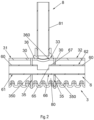
- the heat exchange medium enters the transitional chamber 80 via the connecting tube 81, then passes through the inlets 65 of the heat exchange medium inlet tubes 66 to enter the first distribution tube part 61 and the second distribution tube part 62 of the distribution tube 6, which are located at two sides.
- the heat exchange medium inlet tube 66 arranged on the first inlet manifold part 31 and the heat exchange medium inlet tube 66 arranged on the second inlet manifold part 32 are connected to each other to form a common heat exchange medium inlet tube 66, and the inlet 65 of the heat exchange medium inlet tube 66 is an opening penetrating a tube wall 67 of the common heat exchange medium inlet tube 66.
- the heat exchange medium inlet tube 66 arranged on the first inlet manifold part 31 and the heat exchange medium inlet tube 66 arranged on the second inlet manifold part 32 have ends which are separated from each other, and the inlet 65 of the heat exchange medium inlet tube 66 is an opening at the end 68 of the heat exchange medium inlet tube 66.
- the heat exchange medium inlet tube 66 arranged on the first inlet manifold part 31 and the heat exchange medium inlet tube 66 arranged on the second inlet manifold part 32 are connected to each other to form a common heat exchange medium inlet tube 66, and the inlet 65 of the heat exchange medium inlet tube 66 is an opening penetrating the tube wall 67 of the common heat exchange medium inlet tube 66.
- the connecting tube assembly 8 comprises the connecting tube 81, the connecting tube 81 being connected to the common heat exchange medium inlet tube 66, and in fluid communication with the opening in the tube wall 67 of the common heat exchange medium inlet tube 66.
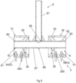
- the connecting tube 81 is located between the first inlet manifold part 31 and the second inlet manifold part 32, and the heat exchange medium enters the heat exchange medium inlet tube 66 directly via the connecting tube 81, e.g. directly enters a centrally located common distribution tube connecting portion of the distribution tube 6, and then enters the first distribution tube part 61 and the second distribution tube part 62 of the distribution tube 6, which are located at the two sides.
- the first inlet manifold part 31 and the second inlet manifold part 32 of the inlet manifold 3 are two separate inlet manifold parts.
- an installation space is provided between the end of the first inlet manifold part 31 and the end of the second inlet manifold part 32.
- the first inlet manifold part 31 and the second inlet manifold part 32 of the inlet manifold 3 are two manifold parts of a single inlet manifold 3.
- the heat exchanger 100 further comprises: multiple heat exchange tubes 5; and fins 7 arranged alternately with the heat exchange tubes 5.
- First ends 51 of the multiple heat exchange tubes 5 are connected to and in fluid communication with the inlet manifold 3.
- the multiple heat exchange tubes 5 comprise first heat exchange tubes 5A which are connected to and in fluid communication with the first inlet manifold part 31 of the inlet manifold 3, and second heat exchange tubes 5B which are connected to and in fluid communication with the second inlet manifold part 32 of the inlet manifold 3.
- the first heat exchange tubes 5A are located at one side
- the second heat exchange tubes 5B are located at the other side.
- the first ends 51 of the first heat exchange tubes 5A are bent towards one side in a thickness direction of the heat exchanger 100, or the first ends 51 of the second heat exchange tubes 5B are bent towards the other side in the thickness direction of the heat exchanger 100, such that the first inlet manifold part 31 and the second inlet manifold part 32 of the inlet manifold 3 are offset in relation to each other in the thickness direction of the heat exchanger 100.
- the first ends 51 of the first heat exchange tubes 5A are bent towards one side in the thickness direction of the heat exchanger 100, and the first ends 51 of the second heat exchange tubes 5B are bent towards the other side in the thickness direction of the heat exchanger 100, such that the first inlet manifold part 31 and the second inlet manifold part 32 of the inlet manifold 3 are offset in relation to each other in the thickness direction of the heat exchanger 100.
- the first inlet manifold part 31 and the second inlet manifold part 32 of the inlet manifold 3 are offset in relation to each other in a direction (the vertical direction in Fig. 8 ) which is perpendicular to the thickness direction of the heat exchanger 100 and to the direction of arrangement of the heat exchange tubes 5. It may be that, based on the embodiments shown in Figs. 6 and 7 , the first inlet manifold part 31 and the second inlet manifold part 32 of the inlet manifold 3 are offset in relation to each other in a direction (the vertical direction in Fig.
- the first inlet manifold part 31 and the second inlet manifold part 32 of the inlet manifold 3 are offset in relation to each other in a direction (the vertical direction in Fig. 7 ) which is perpendicular to the thickness direction of the heat exchanger 100 and to the direction of arrangement of the heat exchange tubes 5.
- the heat exchangers according to these embodiments can fully utilize a heat exchange area in certain installation scenarios, thus increasing heat exchange efficiency.
- the connecting tube assembly 8 comprises a three-way tube 85 and the connecting tube 81, the connecting tube 81 being connected via the three-way tube 85 to the heat exchange medium inlet tube 66 arranged on the first inlet manifold part 31 and the heat exchange medium inlet tube 66 arranged on the second inlet manifold part 32, e.g. connected to the distribution tube connecting portions of the first distribution tube part 61 and the second distribution tube part 62 of the distribution tube 6.
- the heat exchanger 100 further comprises: an outlet manifold 2, the outlet manifold 2 being used for the flow of the heat exchange medium out of the heat exchanger 100, and second ends 51 of the multiple heat exchange tubes 5 are connected to and in fluid communication with the outlet manifold 2.
- the outlet manifold 2 comprises a first outlet manifold part 21 and a second outlet manifold part 22, the first heat exchange tubes 5A are connected to and in fluid communication with the first outlet manifold part 21 of the outlet manifold 2, and the second heat exchange tubes 5B are connected to and in fluid communication with the second outlet manifold part 22 of the outlet manifold 2.
- the multiple heat exchange tubes 5 are arranged in a length direction of the outlet manifold 2. That is, the first heat exchange tubes 5A and the second heat exchange tubes 5B are arranged in the length direction of the outlet manifold 2.
- the heat exchanger 100 further comprises: a first secondary heat exchanger 101 and a second secondary heat exchanger 102.
- the first secondary heat exchanger 101 comprises the first inlet manifold part 31, the first distribution tube part 61, the first outlet manifold part 21 and the first heat exchange tubes 5A.
- the second secondary heat exchanger 102 comprises the second inlet manifold part 32, the second distribution tube part 62, the second outlet manifold part 22 and the second heat exchange tubes 5B.
- An angle is formed between the first secondary heat exchanger 101 and the second secondary heat exchanger 102, wherein the angle may be in the range of 45 degrees to 135 degrees.
- the angle between the first secondary heat exchanger 101 and the second secondary heat exchanger 102 may be in the range of 85 degrees to 95 degrees; for example, the angle between the first secondary heat exchanger 101 and the second secondary heat exchanger 102 is approximately 90 degrees.
- the first outlet manifold part 21 and the second outlet manifold part 22 of the outlet manifold 2 are two separate outlet manifold parts, and connected to each other via an outlet manifold connecting tube 25.
- the first outlet manifold part 21 and the second outlet manifold part 22 of the outlet manifold 2 are two parts of a single outlet manifold. That is, the heat exchangers shown in Figs. 4 and 6 can be bent. If a heat exchanger core body needs to be bent, the heat exchangers shown in Figs. 4 and 6 can be bent easily.
- the fact that the heat exchange medium enters the distribution tube through the middle of the inlet manifold helps to optimize distribution of the heat exchange medium and increase heat exchange efficiency.
- the inlet manifold has been described as comprising the first inlet manifold part and the second inlet manifold part, the inlet manifold could also comprise three or more parts, and correspondingly, the distribution tube could also comprise three or more parts.
Landscapes
- Engineering & Computer Science (AREA)
- Physics & Mathematics (AREA)
- Thermal Sciences (AREA)
- Mechanical Engineering (AREA)
- General Engineering & Computer Science (AREA)
- Geometry (AREA)
- Heat-Exchange Devices With Radiators And Conduit Assemblies (AREA)
Abstract
Description
- The present invention relates to a heat exchanger.
- A heat exchanger comprises heat exchange tubes, an outlet manifold, an inlet manifold and a distribution tube. The distribution tube is arranged in the inlet manifold to distribute a heat exchange medium.
- The object of the present invention is to provide a heat exchanger, whereby, for example, optimization of heat exchange medium distribution and enhancement of heat exchange efficiency can be facilitated.
- Embodiments of the present invention provide a heat exchanger, comprising: an inlet manifold, the inlet manifold being used for the flow of a heat exchange medium into the heat exchanger, and the inlet manifold comprising a first inlet manifold part and a second inlet manifold part, and heat exchange medium inlet tubes, respectively arranged at mutually adjacent ends of the first inlet manifold part and the second inlet manifold part, and in fluid communication with the first inlet manifold part and the second inlet manifold part respectively, the heat exchange medium inlet tube having an inlet.
- According to an embodiment of the present invention, the inlet manifold further comprises: a distribution tube, the distribution tube comprising a first distribution tube part and a second distribution tube part, the first distribution tube part and the second distribution tube part having distribution tube distributing portions respectively arranged in the first inlet manifold part and the second inlet manifold part, and distribution tube connecting portions respectively extending out of the first inlet manifold part and the second inlet manifold part from the distribution tube distributing portions, the distribution tube connecting portions forming the heat exchange medium inlet tubes.
- According to an embodiment of the present invention, the first inlet manifold part and the second inlet manifold part respectively have closure plates which close the mutually adjacent ends of the first inlet manifold part and the second inlet manifold part, the closure plate having a through-hole; and the heat exchange medium inlet tube arranged on the first inlet manifold part and the heat exchange medium inlet tube arranged on the second inlet manifold part extend out through the through-holes of the closure plates of the first inlet manifold part and the second inlet manifold part respectively.
- According to an embodiment of the present invention, the inlet manifold further comprises an inlet manifold connecting part connected between the first inlet manifold part and the second inlet manifold part, a transitional chamber is defined by the inlet manifold connecting part together with the closure plates of the first inlet manifold part and the second inlet manifold part, the heat exchange medium inlet tube arranged on the first inlet manifold part and the heat exchange medium inlet tube arranged on the second inlet manifold part extend out into the transitional chamber through the through-holes of the closure plates of the first inlet manifold part and the second inlet manifold part respectively, and the inlet manifold connecting part has an opening penetrating a tube wall of the inlet manifold connecting part, allowing the heat exchange medium to enter the transitional chamber through the opening in the tube wall of the inlet manifold connecting part.
- According to an embodiment of the present invention, the heat exchanger further comprises a connecting tube assembly, the connecting tube assembly comprising a connecting tube, the connecting tube being connected to the inlet manifold connecting part, and in fluid communication with the transitional chamber via the opening in the tube wall of the inlet manifold connecting part.
- According to an embodiment of the present invention, the heat exchange medium inlet tube arranged on the first inlet manifold part and the heat exchange medium inlet tube arranged on the second inlet manifold part are connected to each other to form a common heat exchange medium inlet tube, and the inlet of the heat exchange medium inlet tube is an opening penetrating a tube wall of the common heat exchange medium inlet tube.
- According to an embodiment of the present invention, the heat exchange medium inlet tube arranged on the first inlet manifold part and the heat exchange medium inlet tube arranged on the second inlet manifold part have ends which are separated from each other, and the inlet of the heat exchange medium inlet tube is an opening at the end of the heat exchange medium inlet tube.
- According to an embodiment of the present invention, the heat exchange medium inlet tube arranged on the first inlet manifold part and the heat exchange medium inlet tube arranged on the second inlet manifold part are connected to each other to form a common heat exchange medium inlet tube, and the inlet of the heat exchange medium inlet tube is an opening penetrating a tube wall of the common heat exchange medium inlet tube; and the heat exchanger further comprises a connecting tube assembly, the connecting tube assembly comprising a connecting tube, the connecting tube being connected to the common heat exchange medium inlet tube, and in fluid communication with the opening in the tube wall of the common heat exchange medium inlet tube.
- According to an embodiment of the present invention, the first inlet manifold part and the second inlet manifold part of the inlet manifold are two separate inlet manifold parts.
- According to an embodiment of the present invention, the first inlet manifold part and the second inlet manifold part of the inlet manifold are two parts of a single inlet manifold.
- According to an embodiment of the present invention, the heat exchanger further comprises multiple heat exchange tubes, first ends of the multiple heat exchange tubes being connected to and in fluid communication with the inlet manifold, the multiple heat exchange tubes comprising a first heat exchange tube which is connected to and in fluid communication with the first inlet manifold part of the inlet manifold, and a second heat exchange tube which is connected to and in fluid communication with the second inlet manifold part of the inlet manifold.
- According to an embodiment of the present invention, in a direction of arrangement of the heat exchange tubes, the first heat exchange tube is located at one side, and the second heat exchange tube is located at the other side.
- According to an embodiment of the present invention, the first end of the first heat exchange tube is bent towards one side in a thickness direction of the heat exchanger, and/or the first end of the second heat exchange tube is bent towards the other side in the thickness direction of the heat exchanger, such that the first inlet manifold part and the second inlet manifold part of the inlet manifold are offset in relation to each other in the thickness direction of the heat exchanger.
- According to an embodiment of the present invention, the first inlet manifold part and the second inlet manifold part of the inlet manifold are offset in relation to each other in a direction which is perpendicular to a thickness direction of the heat exchanger and to a direction of arrangement of the heat exchange tubes.
- According to an embodiment of the present invention, the heat exchanger further comprises a connecting tube assembly, the connecting tube assembly comprising a three-way tube and a connecting tube, the connecting tube being connected via the three-way tube to the heat exchange medium inlet tube arranged on the first inlet manifold part and the heat exchange medium inlet tube arranged on the second inlet manifold part.
- According to an embodiment of the present invention, there is an angle between an axis of the first inlet manifold part and an axis of the second inlet manifold part.
- According to an embodiment of the present invention, the heat exchanger further comprises an outlet manifold, the outlet manifold being used for the flow of the heat exchange medium out of the heat exchanger; second ends of the multiple heat exchange tubes are connected to and in fluid communication with the outlet manifold, and the outlet manifold comprises a first outlet manifold part and a second outlet manifold part, the first heat exchange tube being connected to and in fluid communication with the first outlet manifold part of the outlet manifold, and the second heat exchange tube being connected to and in fluid communication with the second outlet manifold part of the outlet manifold.
- According to an embodiment of the present invention, the first heat exchange tube and the second heat exchange tube are arranged in a length direction of the outlet manifold.
- According to an embodiment of the present invention, the heat exchanger further comprises a first secondary heat exchanger and a second secondary heat exchanger, the first secondary heat exchanger comprising the first inlet manifold part, the first outlet manifold part and the first heat exchange tube, the second secondary heat exchanger comprising the second inlet manifold part, the second outlet manifold part and the second heat exchange tube, and an angle being formed between the first secondary heat exchanger and the second secondary heat exchanger.
- According to an embodiment of the present invention, the angle between the first secondary heat exchanger and the second secondary heat exchanger is in the range of 45 degrees to 135 degrees.
- According to an embodiment of the present invention, the first outlet manifold part and the second outlet manifold part of the outlet manifold are two separate outlet manifold parts, and connected to each other via an outlet manifold connecting tube.
- According to an embodiment of the present invention, the first outlet manifold part and the second outlet manifold part of the outlet manifold are two parts of a single outlet manifold.
- According to an embodiment of the present invention, the first inlet manifold part and the second inlet manifold part respectively have closure plates which close the mutually adjacent ends of the first inlet manifold part and the second inlet manifold part, the closure plate having a through-hole; and the heat exchange medium inlet tube arranged on the first inlet manifold part and the heat exchange medium inlet tube arranged on the second inlet manifold part are in communication with the through-holes of the closure plates of the first inlet manifold part and the second inlet manifold part respectively.
- Using the heat exchanger according to embodiments of the present invention, the fact that the heat exchange medium enters the inlet manifold through the middle of the inlet manifold helps to optimize distribution of the heat exchange medium and increase heat exchange efficiency.
-
-
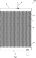
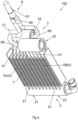
Fig. 1 is a schematic main view of a heat exchanger according to an embodiment of the present invention; -
Fig. 2 is a schematic sectional view of part of the heat exchanger shown inFig. 1 , said part including a connecting tube assembly; -
Fig. 3 is a schematic sectional view of part of a heat exchanger according to another embodiment of the present invention, said part including a connecting tube assembly; -
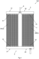
Fig. 4 is a schematic main view of a heat exchanger according to another embodiment of the present invention; -
Fig. 5 is a schematic sectional view of part of the heat exchanger shown inFig. 4 , said part including a connecting tube assembly; -
Fig. 6 is a schematic perspective view of a heat exchanger according to another embodiment of the present invention; -
Fig. 7 is a schematic side view of part of a heat exchanger according to a variant of the embodiment shown inFig. 6 ; -
Fig. 8 is a schematic main view of a heat exchanger according to another variant of the embodiment shown inFig. 6 ; -
Fig. 9 is a schematic top view of a heat exchanger according to another variant of the embodiment shown inFig. 6 ; -
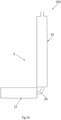
Fig. 10 is a schematic bottom view of a heat exchanger according to another variant of the embodiment shown inFig. 6 ; and -
Fig. 11 is a schematic bottom view of a heat exchanger according to a further variant of the embodiment shown inFig. 6 . - The present invention is explained further below in conjunction with the drawings and specific embodiments.
- Referring to
Figs. 1 - 6 ,8 and9 , aheat exchanger 100 according to embodiments of the present invention comprises: aninlet manifold 3, theinlet manifold 3 being used for the flow of a heat exchange medium into theheat exchanger 100, and theinlet manifold 3 comprising a firstinlet manifold part 31 and a secondinlet manifold part 32; and heat exchangemedium inlet tubes 66, respectively arranged at mutuallyadjacent ends 30 of the firstinlet manifold part 31 and the secondinlet manifold part 32, and in fluid communication with the firstinlet manifold part 31 and the secondinlet manifold part 32 respectively, the heat exchangemedium inlet tube 66 having aninlet 65. - Referring to
Figs. 1 - 6 ,8 and9 , in embodiments of the present invention, theinlet manifold 3 further comprises adistribution tube 6, thedistribution tube 6 comprising: a firstdistribution tube part 61 and a seconddistribution tube part 62, the firstdistribution tube part 61 and the seconddistribution tube part 62 having distributiontube distributing portions 60 respectively arranged in the firstinlet manifold part 31 and the secondinlet manifold part 32, and distribution tube connecting portions which respectively extend out of the firstinlet manifold part 31 and the secondinlet manifold part 32 from the distributiontube distributing portions 60 and form the heat exchangemedium inlet tubes 66. The distributiontube distributing portions 60 may have multiple distributing holes arranged in a longitudinal direction. - Referring to
Figs. 2 ,3 and5 , in embodiments of the present invention, the firstinlet manifold part 31 and the secondinlet manifold part 32 respectively haveclosure plates 35 which close the mutuallyadjacent ends 30 of the firstinlet manifold part 31 and the secondinlet manifold part 32, theclosure plate 35 having a through-hole 350; and the heat exchangemedium inlet tube 66 arranged on the firstinlet manifold part 31 and the heat exchangemedium inlet tube 66 arranged on the secondinlet manifold part 32 extend out through the through-holes 350 of theclosure plates 35 of the firstinlet manifold part 31 and the secondinlet manifold part 32 respectively. If no distributiontube distributing portions 60 are employed, the heat exchangemedium inlet tube 66 arranged on the firstinlet manifold part 31 and the heat exchangemedium inlet tube 66 arranged on the secondinlet manifold part 32 are in communication with the through-holes 350 of theclosure plates 35 of the firstinlet manifold part 31 and the secondinlet manifold part 32 respectively. - Referring to
Figs. 2 and3 , in embodiments of the present invention, theinlet manifold 3 further comprises: an inletmanifold connecting part 33 connected between the firstinlet manifold part 31 and the secondinlet manifold part 32, wherein atransitional chamber 80 is defined by the inletmanifold connecting part 33 together with theclosure plates 35 of the firstinlet manifold part 31 and the secondinlet manifold part 32, the heat exchangemedium inlet tube 66 arranged on the firstinlet manifold part 31 and the heat exchangemedium inlet tube 66 arranged on the secondinlet manifold part 32 extend out into thetransitional chamber 80 through the through-holes 350 of theclosure plates 35 of the firstinlet manifold part 31 and the secondinlet manifold part 32 respectively, and the inletmanifold connecting part 33 has an opening 360 penetrating atube wall 36 of the inletmanifold connecting part 33, allowing a heat exchange medium to enter thetransitional chamber 80 through the opening 360 in thetube wall 36 of the inletmanifold connecting part 33. Theheat exchanger 100 further comprises aconnecting tube assembly 8, theconnecting tube assembly 8 comprising aconnecting tube 81, the connectingtube 81 being connected to the inletmanifold connecting part 33, and in fluid communication with thetransitional chamber 80 via the opening 360 in thetube wall 36 of the inletmanifold connecting part 33. The heat exchange medium enters thetransitional chamber 80 via theconnecting tube 81, then passes through theinlets 65 of the heat exchangemedium inlet tubes 66 to enter the firstdistribution tube part 61 and the seconddistribution tube part 62 of thedistribution tube 6, which are located at two sides. - Referring to
Figs. 2 ,4 and5 , in some embodiments of the present invention, the heat exchangemedium inlet tube 66 arranged on the firstinlet manifold part 31 and the heat exchangemedium inlet tube 66 arranged on the secondinlet manifold part 32 are connected to each other to form a common heat exchangemedium inlet tube 66, and theinlet 65 of the heat exchangemedium inlet tube 66 is an opening penetrating atube wall 67 of the common heat exchangemedium inlet tube 66. Referring toFigs. 3 ,6 ,8 and9 , in other embodiments of the present invention, the heat exchangemedium inlet tube 66 arranged on the firstinlet manifold part 31 and the heat exchangemedium inlet tube 66 arranged on the secondinlet manifold part 32 have ends which are separated from each other, and theinlet 65 of the heat exchangemedium inlet tube 66 is an opening at theend 68 of the heat exchangemedium inlet tube 66. - Referring to
Figs. 4 and5 , in embodiments of the present invention, the heat exchangemedium inlet tube 66 arranged on the firstinlet manifold part 31 and the heat exchangemedium inlet tube 66 arranged on the secondinlet manifold part 32 are connected to each other to form a common heat exchangemedium inlet tube 66, and theinlet 65 of the heat exchangemedium inlet tube 66 is an opening penetrating thetube wall 67 of the common heat exchangemedium inlet tube 66. Theconnecting tube assembly 8 comprises theconnecting tube 81, the connectingtube 81 being connected to the common heat exchangemedium inlet tube 66, and in fluid communication with the opening in thetube wall 67 of the common heat exchangemedium inlet tube 66. The connectingtube 81 is located between the firstinlet manifold part 31 and the secondinlet manifold part 32, and the heat exchange medium enters the heat exchangemedium inlet tube 66 directly via theconnecting tube 81, e.g. directly enters a centrally located common distribution tube connecting portion of thedistribution tube 6, and then enters the firstdistribution tube part 61 and the seconddistribution tube part 62 of thedistribution tube 6, which are located at the two sides. - Referring to
Figs. 4 - 6 ,8 and9 , in some embodiments of the present invention, the firstinlet manifold part 31 and the secondinlet manifold part 32 of theinlet manifold 3 are two separate inlet manifold parts. For example, there is an angle between an axis of the firstinlet manifold part 31 and an axis of the secondinlet manifold part 32. Thus, an installation space is provided between the end of the firstinlet manifold part 31 and the end of the secondinlet manifold part 32. Referring toFigs. 1 - 3 , in other embodiments of the present invention, the firstinlet manifold part 31 and the secondinlet manifold part 32 of theinlet manifold 3 are two manifold parts of asingle inlet manifold 3. - Referring to
Figs. 1 ,4 and6 - 8 , in embodiments of the present invention, theheat exchanger 100 further comprises: multipleheat exchange tubes 5; andfins 7 arranged alternately with theheat exchange tubes 5.First ends 51 of the multipleheat exchange tubes 5 are connected to and in fluid communication with theinlet manifold 3. Referring toFigs. 4 - 9 , the multipleheat exchange tubes 5 comprise firstheat exchange tubes 5A which are connected to and in fluid communication with the firstinlet manifold part 31 of theinlet manifold 3, and secondheat exchange tubes 5B which are connected to and in fluid communication with the secondinlet manifold part 32 of theinlet manifold 3. In a direction of arrangement of theheat exchange tubes 5, the firstheat exchange tubes 5A are located at one side, and the secondheat exchange tubes 5B are located at the other side. - Referring to
Fig. 6 , in some embodiments of the present invention, the first ends 51 of the firstheat exchange tubes 5A are bent towards one side in a thickness direction of theheat exchanger 100, or the first ends 51 of the secondheat exchange tubes 5B are bent towards the other side in the thickness direction of theheat exchanger 100, such that the first inletmanifold part 31 and the second inletmanifold part 32 of theinlet manifold 3 are offset in relation to each other in the thickness direction of theheat exchanger 100. Referring toFig. 7 , in other embodiments of the present invention, the first ends 51 of the firstheat exchange tubes 5A are bent towards one side in the thickness direction of theheat exchanger 100, and the first ends 51 of the secondheat exchange tubes 5B are bent towards the other side in the thickness direction of theheat exchanger 100, such that the first inletmanifold part 31 and the second inletmanifold part 32 of theinlet manifold 3 are offset in relation to each other in the thickness direction of theheat exchanger 100. According to this embodiment of the present invention, it can be ensured that the heat exchange tubes are uninterrupted over the entire wind-facing side, thus increasing the heat exchange area. - Referring to
Fig. 8 , in embodiments of the present invention, the first inletmanifold part 31 and the second inletmanifold part 32 of theinlet manifold 3 are offset in relation to each other in a direction (the vertical direction inFig. 8 ) which is perpendicular to the thickness direction of theheat exchanger 100 and to the direction of arrangement of theheat exchange tubes 5. It may be that, based on the embodiments shown inFigs. 6 and7 , the first inletmanifold part 31 and the second inletmanifold part 32 of theinlet manifold 3 are offset in relation to each other in a direction (the vertical direction inFig. 7 ) which is perpendicular to the thickness direction of theheat exchanger 100 and to the direction of arrangement of theheat exchange tubes 5; or based on the embodiment shown inFig. 4 , the first inletmanifold part 31 and the second inletmanifold part 32 of theinlet manifold 3 are offset in relation to each other in a direction (the vertical direction inFig. 7 ) which is perpendicular to the thickness direction of theheat exchanger 100 and to the direction of arrangement of theheat exchange tubes 5. The heat exchangers according to these embodiments can fully utilize a heat exchange area in certain installation scenarios, thus increasing heat exchange efficiency. - Referring to
Figs. 6 and8 , in embodiments of the present invention, the connectingtube assembly 8 comprises a three-way tube 85 and the connectingtube 81, the connectingtube 81 being connected via the three-way tube 85 to the heat exchangemedium inlet tube 66 arranged on the first inletmanifold part 31 and the heat exchangemedium inlet tube 66 arranged on the second inletmanifold part 32, e.g. connected to the distribution tube connecting portions of the firstdistribution tube part 61 and the seconddistribution tube part 62 of thedistribution tube 6. - Referring to
Figs. 1 ,4 ,6 ,8 ,10 and11 , in embodiments of the present invention, theheat exchanger 100 further comprises: anoutlet manifold 2, theoutlet manifold 2 being used for the flow of the heat exchange medium out of theheat exchanger 100, and second ends 51 of the multipleheat exchange tubes 5 are connected to and in fluid communication with theoutlet manifold 2. Referring toFigs. 4 ,6 ,8 ,10 and11 , theoutlet manifold 2 comprises a first outletmanifold part 21 and a second outletmanifold part 22, the firstheat exchange tubes 5A are connected to and in fluid communication with the first outletmanifold part 21 of theoutlet manifold 2, and the secondheat exchange tubes 5B are connected to and in fluid communication with the second outletmanifold part 22 of theoutlet manifold 2. The multipleheat exchange tubes 5 are arranged in a length direction of theoutlet manifold 2. That is, the firstheat exchange tubes 5A and the secondheat exchange tubes 5B are arranged in the length direction of theoutlet manifold 2. Theheat exchanger 100 further comprises: a first secondary heat exchanger 101 and a second secondary heat exchanger 102. The first secondary heat exchanger 101 comprises the first inletmanifold part 31, the firstdistribution tube part 61, the first outletmanifold part 21 and the firstheat exchange tubes 5A. The second secondary heat exchanger 102 comprises the second inletmanifold part 32, the seconddistribution tube part 62, the second outletmanifold part 22 and the secondheat exchange tubes 5B. An angle is formed between the first secondary heat exchanger 101 and the second secondary heat exchanger 102, wherein the angle may be in the range of 45 degrees to 135 degrees. The angle between the first secondary heat exchanger 101 and the second secondary heat exchanger 102 may be in the range of 85 degrees to 95 degrees; for example, the angle between the first secondary heat exchanger 101 and the second secondary heat exchanger 102 is approximately 90 degrees. According to an example of the present invention, as shown inFig. 10 , the first outletmanifold part 21 and the second outletmanifold part 22 of theoutlet manifold 2 are two separate outlet manifold parts, and connected to each other via an outletmanifold connecting tube 25. According to another example of the present invention, as shown inFig. 11 , the first outletmanifold part 21 and the second outletmanifold part 22 of theoutlet manifold 2 are two parts of a single outlet manifold. That is, the heat exchangers shown inFigs. 4 and6 can be bent. If a heat exchanger core body needs to be bent, the heat exchangers shown inFigs. 4 and6 can be bent easily. - Using the heat exchanger according to embodiments of the present invention, the fact that the heat exchange medium enters the distribution tube through the middle of the inlet manifold helps to optimize distribution of the heat exchange medium and increase heat exchange efficiency.
- Although the above embodiments have been described, certain features in the above embodiments can be combined to form new embodiments.
- For example, although the inlet manifold has been described as comprising the first inlet manifold part and the second inlet manifold part, the inlet manifold could also comprise three or more parts, and correspondingly, the distribution tube could also comprise three or more parts.
Claims (23)
- A heat exchanger, comprising:
an inlet manifold, the inlet manifold being used for the flow of a heat exchange medium into the heat exchanger, and the inlet manifold comprising a first inlet manifold part and a second inlet manifold part, and heat exchange medium inlet tubes, respectively arranged at mutually adjacent ends of the first inlet manifold part and the second inlet manifold part, and in fluid communication with the first inlet manifold part and the second inlet manifold part respectively, the heat exchange medium inlet tube having an inlet. - The heat exchanger as claimed in claim 1, the inlet manifold further comprising:
a distribution tube, the distribution tube comprising a first distribution tube part and a second distribution tube part, the first distribution tube part and the second distribution tube part having distribution tube distributing portions respectively arranged in the first inlet manifold part and the second inlet manifold part, and distribution tube connecting portions respectively extending out of the first inlet manifold part and the second inlet manifold part from the distribution tube distributing portions, the distribution tube connecting portions forming the heat exchange medium inlet tubes. - The heat exchanger as claimed in claim 1, wherein:the first inlet manifold part and the second inlet manifold part respectively have closure plates which close the mutually adjacent ends of the first inlet manifold part and the second inlet manifold part, the closure plate having a through-hole; andthe heat exchange medium inlet tube arranged on the first inlet manifold part and the heat exchange medium inlet tube arranged on the second inlet manifold part extend out through the through-holes of the closure plates of the first inlet manifold part and the second inlet manifold part respectively.
- The heat exchanger as claimed in claim 3, wherein:
the inlet manifold further comprises an inlet manifold connecting part connected between the first inlet manifold part and the second inlet manifold part, a transitional chamber is defined by the inlet manifold connecting part together with the closure plates of the first inlet manifold part and the second inlet manifold part, the heat exchange medium inlet tube arranged on the first inlet manifold part and the heat exchange medium inlet tube arranged on the second inlet manifold part extend out into the transitional chamber through the through-holes of the closure plates of the first inlet manifold part and the second inlet manifold part respectively, and the inlet manifold connecting part has an opening penetrating a tube wall of the inlet manifold connecting part, allowing the heat exchange medium to enter the transitional chamber through the opening in the tube wall of the inlet manifold connecting part. - The heat exchanger as claimed in claim 4, further comprising:
a connecting tube assembly, the connecting tube assembly comprising a connecting tube, the connecting tube being connected to the inlet manifold connecting part, and in fluid communication with the transitional chamber via the opening in the tube wall of the inlet manifold connecting part. - The heat exchanger as claimed in any one of claims 1 - 5, wherein:
the heat exchange medium inlet tube arranged on the first inlet manifold part and the heat exchange medium inlet tube arranged on the second inlet manifold part are connected to each other to form a common heat exchange medium inlet tube, and the inlet of the heat exchange medium inlet tube is an opening penetrating a tube wall of the common heat exchange medium inlet tube. - The heat exchanger as claimed in any one of claims 1 - 5, wherein:
the heat exchange medium inlet tube arranged on the first inlet manifold part and the heat exchange medium inlet tube arranged on the second inlet manifold part have ends which are separated from each other, and the inlet of the heat exchange medium inlet tube is an opening at the end of the heat exchange medium inlet tube. - The heat exchanger as claimed in any one of claims 1 - 3, wherein:the heat exchange medium inlet tube arranged on the first inlet manifold part and the heat exchange medium inlet tube arranged on the second inlet manifold part are connected to each other to form a common heat exchange medium inlet tube, and the inlet of the heat exchange medium inlet tube is an opening penetrating a tube wall of the common heat exchange medium inlet tube; andthe heat exchanger further comprises a connecting tube assembly, the connecting tube assembly comprising a connecting tube, the connecting tube being connected to the common heat exchange medium inlet tube, and in fluid communication with the opening in the tube wall of the common heat exchange medium inlet tube.
- The heat exchanger as claimed in claim 1, wherein:
the first inlet manifold part and the second inlet manifold part of the inlet manifold are two separate inlet manifold parts. - The heat exchanger as claimed in claim 1, wherein:
the first inlet manifold part and the second inlet manifold part of the inlet manifold are two parts of a single inlet manifold. - The heat exchanger as claimed in claim 1 or 9, further comprising:
multiple heat exchange tubes, first ends of the multiple heat exchange tubes being connected to and in fluid communication with the inlet manifold, the multiple heat exchange tubes comprising a first heat exchange tube which is connected to and in fluid communication with the first inlet manifold part of the inlet manifold, and a second heat exchange tube which is connected to and in fluid communication with the second inlet manifold part of the inlet manifold. - The heat exchanger as claimed in claim 11, wherein:
in a direction of arrangement of the heat exchange tubes, the first heat exchange tube is located at one side, and the second heat exchange tube is located at the other side. - The heat exchanger as claimed in claim 11, wherein:
the first end of the first heat exchange tube is bent towards one side in a thickness direction of the heat exchanger, and/or the first end of the second heat exchange tube is bent towards the other side in the thickness direction of the heat exchanger, such that the first inlet manifold part and the second inlet manifold part of the inlet manifold are offset in relation to each other in the thickness direction of the heat exchanger. - The heat exchanger as claimed in any one of claims 11 - 13, wherein:
the first inlet manifold part and the second inlet manifold part of the inlet manifold are offset in relation to each other in a direction which is perpendicular to a thickness direction of the heat exchanger and to a direction of arrangement of the heat exchange tubes. - The heat exchanger as claimed in claim 9, further comprising:
a connecting tube assembly, the connecting tube assembly comprising a three-way tube and a connecting tube, the connecting tube being connected via the three-way tube to the heat exchange medium inlet tube arranged on the first inlet manifold part and the heat exchange medium inlet tube arranged on the second inlet manifold part. - The heat exchanger as claimed in claim 9, wherein:
there is an angle between an axis of the first inlet manifold part and an axis of the second inlet manifold part. - The heat exchanger as claimed in claim 11, further comprising:
an outlet manifold, the outlet manifold being used for the flow of the heat exchange medium out of the heat exchanger; second ends of the multiple heat exchange tubes are connected to and in fluid communication with the outlet manifold, and the outlet manifold comprises a first outlet manifold part and a second outlet manifold part, the first heat exchange tube being connected to and in fluid communication with the first outlet manifold part of the outlet manifold, and the second heat exchange tube being connected to and in fluid communication with the second outlet manifold part of the outlet manifold. - The heat exchanger as claimed in claim 17, wherein:
the first heat exchange tube and the second heat exchange tube are arranged in a length direction of the outlet manifold. - The heat exchanger as claimed in claim 17, further comprising:
a first secondary heat exchanger and a second secondary heat exchanger, the first secondary heat exchanger comprising the first inlet manifold part, the first outlet manifold part and the first heat exchange tube, the second secondary heat exchanger comprising the second inlet manifold part, the second outlet manifold part and the second heat exchange tube, and an angle being formed between the first secondary heat exchanger and the second secondary heat exchanger. - The heat exchanger as claimed in claim 19, wherein:
the angle between the first secondary heat exchanger and the second secondary heat exchanger is in the range of 45 degrees to 135 degrees. - The heat exchanger as claimed in claim 17, wherein:
the first outlet manifold part and the second outlet manifold part of the outlet manifold are two separate outlet manifold parts, and connected to each other via an outlet manifold connecting tube. - The heat exchanger as claimed in claim 17, wherein:
the first outlet manifold part and the second outlet manifold part of the outlet manifold are two parts of a single outlet manifold. - The heat exchanger as claimed in claim 1, wherein:the first inlet manifold part and the second inlet manifold part respectively have closure plates which close the mutually adjacent ends of the first inlet manifold part and the second inlet manifold part, the closure plate having a through-hole; andthe heat exchange medium inlet tube arranged on the first inlet manifold part and the heat exchange medium inlet tube arranged on the second inlet manifold part are in communication with the through-holes of the closure plates of the first inlet manifold part and the second inlet manifold part respectively.
Applications Claiming Priority (2)
| Application Number | Priority Date | Filing Date | Title |
|---|---|---|---|
| CN202210996418.7A CN117628930B (en) | 2022-08-18 | 2022-08-18 | Heat Exchanger |
| PCT/CN2023/101025 WO2024037171A1 (en) | 2022-08-18 | 2023-06-19 | Heat exchanger |
Publications (1)
| Publication Number | Publication Date |
|---|---|
| EP4575378A1 true EP4575378A1 (en) | 2025-06-25 |
Family
ID=89940598
Family Applications (1)
| Application Number | Title | Priority Date | Filing Date |
|---|---|---|---|
| EP23854076.9A Withdrawn EP4575378A1 (en) | 2022-08-18 | 2023-06-19 | Heat exchanger |
Country Status (5)
| Country | Link |
|---|---|
| US (1) | US20260022894A1 (en) |
| EP (1) | EP4575378A1 (en) |
| CN (1) | CN117628930B (en) |
| MX (1) | MX2025001647A (en) |
| WO (1) | WO2024037171A1 (en) |
Family Cites Families (8)
| Publication number | Priority date | Publication date | Assignee | Title |
|---|---|---|---|---|
| JPH05118705A (en) * | 1991-10-31 | 1993-05-14 | Aisin Seiki Co Ltd | Heat exchanger |
| CN103063076B (en) * | 2012-11-21 | 2015-03-11 | 三花控股集团有限公司 | Heat exchanger |
| JP2015055411A (en) * | 2013-09-11 | 2015-03-23 | ダイキン工業株式会社 | Heat exchanger and air conditioner |
| JP5754490B2 (en) * | 2013-09-30 | 2015-07-29 | ダイキン工業株式会社 | Heat exchanger and air conditioner |
| CN107270591B (en) * | 2017-07-24 | 2022-11-18 | 江苏必领能源科技有限公司 | Two-phase distributor for falling film evaporator |
| CN208635379U (en) * | 2018-06-04 | 2019-03-22 | 浙江盾安热工科技有限公司 | The part flow arrangement and its micro-channel heat exchanger of micro-channel heat exchanger |
| KR20220047082A (en) * | 2020-10-08 | 2022-04-15 | 비에이치아이 주식회사 | Upper Harp Header for harp Module of HRSG |
| CN215810397U (en) * | 2021-05-06 | 2022-02-11 | 浙江盾安热工科技有限公司 | Micro-channel heat exchange structure |
-
2022
- 2022-08-18 CN CN202210996418.7A patent/CN117628930B/en active Active
-
2023
- 2023-06-19 WO PCT/CN2023/101025 patent/WO2024037171A1/en not_active Ceased
- 2023-06-19 US US18/995,703 patent/US20260022894A1/en active Pending
- 2023-06-19 EP EP23854076.9A patent/EP4575378A1/en not_active Withdrawn
-
2025
- 2025-02-10 MX MX2025001647A patent/MX2025001647A/en unknown
Also Published As
| Publication number | Publication date |
|---|---|
| MX2025001647A (en) | 2025-03-07 |
| US20260022894A1 (en) | 2026-01-22 |
| WO2024037171A1 (en) | 2024-02-22 |
| CN117628930A (en) | 2024-03-01 |
| CN117628930B (en) | 2025-06-13 |
Similar Documents
| Publication | Publication Date | Title |
|---|---|---|
| US5211222A (en) | Heat exchanger | |
| US7011149B2 (en) | Heat exchanger | |
| US11971224B2 (en) | Plate-fin heat exchanger | |
| US20130240191A1 (en) | Manifold fluid communication plate | |
| US20120222848A1 (en) | Integrated counter cross flow condenser | |
| WO2017097133A1 (en) | Heat exchanger | |
| JP2018532093A (en) | Heat exchanger | |
| EP3465049B1 (en) | Counter-flow heat exchanger | |
| CN222231371U (en) | Heat exchanger and heat exchange device | |
| WO2024001737A1 (en) | Heat exchanger | |
| US2327491A (en) | Sectional heat exchanger | |
| JP7471281B2 (en) | Plate heat exchanger structure and module structure | |
| US20260022894A1 (en) | Heat exchanger | |
| CN111256392B (en) | Heat exchanger | |
| WO2025256616A1 (en) | Battery-pack cooling system and battery pack | |
| CN101776411A (en) | Flat pipe assembly and heat exchanger having same | |
| CN101782296A (en) | Micro-channel heat exchanger | |
| CN115769040A (en) | heat exchanger | |
| CN218523782U (en) | Microchannel heat exchanger and air conditioner | |
| EP3572743B1 (en) | Heat exchanger assembly | |
| CN216954186U (en) | Heat exchange partition plate and counter-flow heat exchanger used for middle section position of heat exchange pipeline | |
| CN216482483U (en) | Flow collecting structure, micro-channel heat exchanger and air conditioner | |
| JPH11281287A (en) | Heat exchanger | |
| CN115900399A (en) | heat exchanger | |
| JPH11281290A5 (en) |
Legal Events
| Date | Code | Title | Description |
|---|---|---|---|
| STAA | Information on the status of an ep patent application or granted ep patent |
Free format text: STATUS: THE INTERNATIONAL PUBLICATION HAS BEEN MADE |
|
| PUAI | Public reference made under article 153(3) epc to a published international application that has entered the european phase |
Free format text: ORIGINAL CODE: 0009012 |
|
| STAA | Information on the status of an ep patent application or granted ep patent |
Free format text: STATUS: REQUEST FOR EXAMINATION WAS MADE |
|
| 17P | Request for examination filed |
Effective date: 20250226 |
|
| AK | Designated contracting states |
Kind code of ref document: A1 Designated state(s): AL AT BE BG CH CY CZ DE DK EE ES FI FR GB GR HR HU IE IS IT LI LT LU LV MC ME MK MT NL NO PL PT RO RS SE SI SK SM TR |
|
| DAV | Request for validation of the european patent (deleted) | ||
| DAX | Request for extension of the european patent (deleted) | ||
| STAA | Information on the status of an ep patent application or granted ep patent |
Free format text: STATUS: THE APPLICATION HAS BEEN WITHDRAWN |
|
| RIC1 | Information provided on ipc code assigned before grant |
Ipc: F28F 9/02 20060101AFI20260507BHEP Ipc: F28D 1/053 20060101ALI20260507BHEP Ipc: F25B 39/00 20060101ALI20260507BHEP Ipc: F28F 1/02 20060101ALI20260507BHEP |
|
| 18W | Application withdrawn |
Effective date: 20260601 |