EP4575320A1 - Household appliance comprising a door handle - Google Patents
Household appliance comprising a door handle Download PDFInfo
- Publication number
- EP4575320A1 EP4575320A1 EP24217638.6A EP24217638A EP4575320A1 EP 4575320 A1 EP4575320 A1 EP 4575320A1 EP 24217638 A EP24217638 A EP 24217638A EP 4575320 A1 EP4575320 A1 EP 4575320A1
- Authority
- EP
- European Patent Office
- Prior art keywords
- door
- handle
- household appliance
- touch
- electrode
- Prior art date
- Legal status (The legal status is an assumption and is not a legal conclusion. Google has not performed a legal analysis and makes no representation as to the accuracy of the status listed.)
- Withdrawn
Links
Images



Classifications
-
- A—HUMAN NECESSITIES
- A47—FURNITURE; DOMESTIC ARTICLES OR APPLIANCES; COFFEE MILLS; SPICE MILLS; SUCTION CLEANERS IN GENERAL
- A47J—KITCHEN EQUIPMENT; COFFEE MILLS; SPICE MILLS; APPARATUS FOR MAKING BEVERAGES
- A47J37/00—Baking; Roasting; Grilling; Frying
- A47J37/06—Roasters; Grills; Sandwich grills
- A47J37/0623—Small-size cooking ovens, i.e. defining an at least partially closed cooking cavity
- A47J37/0664—Accessories
-
- F—MECHANICAL ENGINEERING; LIGHTING; HEATING; WEAPONS; BLASTING
- F24—HEATING; RANGES; VENTILATING
- F24C—DOMESTIC STOVES OR RANGES ; DETAILS OF DOMESTIC STOVES OR RANGES, OF GENERAL APPLICATION
- F24C15/00—Details
- F24C15/02—Doors specially adapted for stoves or ranges
- F24C15/024—Handles
-
- A—HUMAN NECESSITIES
- A47—FURNITURE; DOMESTIC ARTICLES OR APPLIANCES; COFFEE MILLS; SPICE MILLS; SUCTION CLEANERS IN GENERAL
- A47L—DOMESTIC WASHING OR CLEANING; SUCTION CLEANERS IN GENERAL
- A47L15/00—Washing or rinsing machines for crockery or tableware
-
- A—HUMAN NECESSITIES
- A47—FURNITURE; DOMESTIC ARTICLES OR APPLIANCES; COFFEE MILLS; SPICE MILLS; SUCTION CLEANERS IN GENERAL
- A47L—DOMESTIC WASHING OR CLEANING; SUCTION CLEANERS IN GENERAL
- A47L15/00—Washing or rinsing machines for crockery or tableware
- A47L15/42—Details
-
- A—HUMAN NECESSITIES
- A47—FURNITURE; DOMESTIC ARTICLES OR APPLIANCES; COFFEE MILLS; SPICE MILLS; SUCTION CLEANERS IN GENERAL
- A47L—DOMESTIC WASHING OR CLEANING; SUCTION CLEANERS IN GENERAL
- A47L15/00—Washing or rinsing machines for crockery or tableware
- A47L15/42—Details
- A47L15/4251—Details of the casing
- A47L15/4257—Details of the loading door
-
- D—TEXTILES; PAPER
- D06—TREATMENT OF TEXTILES OR THE LIKE; LAUNDERING; FLEXIBLE MATERIALS NOT OTHERWISE PROVIDED FOR
- D06F—LAUNDERING, DRYING, IRONING, PRESSING OR FOLDING TEXTILE ARTICLES
- D06F39/00—Details of washing machines not specific to a single type of machines covered by groups D06F9/00 - D06F27/00
- D06F39/12—Casings; Tubs
- D06F39/14—Doors or covers; Securing means therefor
-
- E—FIXED CONSTRUCTIONS
- E05—LOCKS; KEYS; WINDOW OR DOOR FITTINGS; SAFES
- E05B—LOCKS; ACCESSORIES THEREFOR; HANDCUFFS
- E05B1/00—Knobs or handles for wings; Knobs, handles, or press buttons for locks or latches on wings
- E05B1/0015—Knobs or handles which do not operate the bolt or lock, e.g. non-movable; Mounting thereof
-
- F—MECHANICAL ENGINEERING; LIGHTING; HEATING; WEAPONS; BLASTING
- F24—HEATING; RANGES; VENTILATING
- F24C—DOMESTIC STOVES OR RANGES ; DETAILS OF DOMESTIC STOVES OR RANGES, OF GENERAL APPLICATION
- F24C7/00—Stoves or ranges heated by electric energy
- F24C7/08—Arrangement or mounting of control or safety devices
- F24C7/082—Arrangement or mounting of control or safety devices on ranges, e.g. control panels, illumination
- F24C7/085—Arrangement or mounting of control or safety devices on ranges, e.g. control panels, illumination on baking ovens
-
- F—MECHANICAL ENGINEERING; LIGHTING; HEATING; WEAPONS; BLASTING
- F24—HEATING; RANGES; VENTILATING
- F24C—DOMESTIC STOVES OR RANGES ; DETAILS OF DOMESTIC STOVES OR RANGES, OF GENERAL APPLICATION
- F24C7/00—Stoves or ranges heated by electric energy
- F24C7/08—Arrangement or mounting of control or safety devices
- F24C7/082—Arrangement or mounting of control or safety devices on ranges, e.g. control panels, illumination
- F24C7/086—Arrangement or mounting of control or safety devices on ranges, e.g. control panels, illumination touch control
-
- F—MECHANICAL ENGINEERING; LIGHTING; HEATING; WEAPONS; BLASTING
- F25—REFRIGERATION OR COOLING; COMBINED HEATING AND REFRIGERATION SYSTEMS; HEAT PUMP SYSTEMS; MANUFACTURE OR STORAGE OF ICE; LIQUEFACTION SOLIDIFICATION OF GASES
- F25D—REFRIGERATORS; COLD ROOMS; ICE-BOXES; COOLING OR FREEZING APPARATUS NOT OTHERWISE PROVIDED FOR
- F25D23/00—General constructional features
- F25D23/02—Doors; Covers
-
- F—MECHANICAL ENGINEERING; LIGHTING; HEATING; WEAPONS; BLASTING
- F25—REFRIGERATION OR COOLING; COMBINED HEATING AND REFRIGERATION SYSTEMS; HEAT PUMP SYSTEMS; MANUFACTURE OR STORAGE OF ICE; LIQUEFACTION SOLIDIFICATION OF GASES
- F25D—REFRIGERATORS; COLD ROOMS; ICE-BOXES; COOLING OR FREEZING APPARATUS NOT OTHERWISE PROVIDED FOR
- F25D23/00—General constructional features
- F25D23/02—Doors; Covers
- F25D23/028—Details
-
- H—ELECTRICITY
- H03—ELECTRONIC CIRCUITRY
- H03K—PULSE TECHNIQUE
- H03K17/00—Electronic switching or gating, i.e. not by contact-making and –breaking
- H03K17/94—Electronic switching or gating, i.e. not by contact-making and –breaking characterised by the way in which the control signals are generated
- H03K17/96—Touch switches
- H03K17/962—Capacitive touch switches
-
- H—ELECTRICITY
- H03—ELECTRONIC CIRCUITRY
- H03K—PULSE TECHNIQUE
- H03K2217/00—Indexing scheme related to electronic switching or gating, i.e. not by contact-making or -breaking covered by H03K17/00
- H03K2217/94—Indexing scheme related to electronic switching or gating, i.e. not by contact-making or -breaking covered by H03K17/00 characterised by the way in which the control signal is generated
- H03K2217/96—Touch switches
- H03K2217/9607—Capacitive touch switches
- H03K2217/960755—Constructional details of capacitive touch and proximity switches
- H03K2217/96077—Constructional details of capacitive touch and proximity switches comprising an electrode which is floating
Definitions
- the present invention relates to a household appliance comprising a door handle arranged on the outside of the door of the household appliance, by means of which it is possible to close the interior of the household appliance in relation to the surroundings of the said household appliance, wherein the said door handle comprises at least a part of an electronic system for cooperation between the household appliance and its user.
- the household appliance referred to above is, for example, disclosed in patent applications WO2020046150A1 , EP3034948A1 , WO2020046151A1 .
- the said known solutions mainly relate to the integration of an electronic touch sensing module on/inside the door handle of the household appliance or inside its door, which significantly limits the design of the handle or door of the said appliance.
- the said known solutions require an electrical connection between the door of the household appliance and a control unit of the said appliance, which cooperates with the said electronic module either via dedicated hinges or electric conductors.
- the specified characteristics present significant shortcomings that consequently limit the design and usefulness of the household appliance, prevent simple upgrades of existing appliances and complicate the assembly of the final household appliance. The above characteristics also result in higher costs of manufacturing the appliance.
- the object of the present invention is to create a household appliance of the type referred to above, which would remedy the shortcomings of known solutions.
- the present invention relates to a household appliance comprising a door handle, which is arranged on the outside of a household appliance door, by means of which it is possible to close the interior of the household appliance in relation to the surroundings of the said household appliance, wherein the said door handle comprises at least an electronic system for cooperation between the household appliance and the user of the handle of the household appliance or to enable the sensing of touch commands of the user.
- Touch sensing is based on a technology that measures the capacity between the handle of the appliance and/or any other electrically conductive surface on the appliance and the electric potential of earth.
- a household appliance 1 such as an oven, refrigerator, dish washer, washing machine, or similar, comprises a housing 2 with at least one compartment 3 for receiving the item to be heat-treated, stored, or similar, wherein at least one said compartment 3 can be closed by means of a single-section or multi-section door 4, which is fixed to the housing 2 of the household appliance 1 by means of hinges, preferably in a way that the said door 4 is easily removable.
- the said door 4 can be opened or closed by means of a handle 5, which is connected to the door 4.
- the said handle 5 of the door 4 of the household appliance 1 is at least partly made of an electrically conductive material, such as metal.
- the said handle 5, by means of which it is possible to handle the door 4 of the household appliance 1, is, according to the present invention, also provided as an interface for sensing the touch of a user 6, wherein the said handle 5 must be electrically insulated from other electrically conductive elements of the door 4 of the household appliance 1 and the housing 2 of the household appliance 1.
- an electronic module 7 arranged inside the housing 2 of the household appliance 1, in the area above the door aperture, which can be closed by means of the door 4, is an electronic module 7.
- the latter is preferably arranged in the area directly above the said door aperture, which can be closed by means of the door 4.
- the said electronic module 7 comprises an electronic circuit 8, a controller 9 with integrated software that facilitates capacity measurements" which make it possible to sense the touch of the user6, and a first electrode 10.
- the electronic module 7 is arranged in such a way that the first electrode 10 is electrically insulated from the housing 2 of the household appliance 1 or any electrically conductive material.
- a capacitive coupler 11 comprises the first electrode 10, which is connected to the electronic module 7 and arranged in the area above the door aperture, which can be closed by means of the door 4, and a second electrode 12, which is arranged on the side of the said door 4 and spaced from the said first electrode 10.
- the said electrodes 10, 12 are electrically insulated from each other, for instance by means of an air gap a.
- the said capacitive coupler 11 facilitates indirect measurement of capacity between the handle 5 of the door 4 of the household appliance 1 and the electric potential of the earth in such a way that the first electrode 10 of the electronic module 7 is galvanically isolated from the handle 5 of the household appliance 1, while the second electrode 12 is, by means of a conductor 13, galvanically connected to the handle 5 of the household appliance 1, which can be touched by the user 6.
- the said first electrode 10 is formed in such a way that it allows for the compensation of mechanical deviations and structural strain in the manufacture, assembly, and use of the household appliance 1 according to the invention, wherein it is, for example, formed from a flexible material in the manner of a spring.
- the said second electrode 12 which is arranged on the side of the said door 4 of the household appliance 1, is arranged on the upper rear side of the door 4 in such a way that it is aligned with the opposite first electrode 10 whenever the door 4 of the household appliance 1 is in a position that closes the said compartment 3.
- the said second electrode 12 is electrically connected to the handle 5 of the door 4 of the household appliance 1 by means of electric conductors or other electrically conductive parts. At least one of the said electrodes 10, 12 is electrically insulated from any other electrically conductive part of the household appliance 1.
- the said second electrode 12 is, by means of an insulating element 14, electrically insulated from any other electrically conductive part of the household appliance 1.
- a user interface 15 with a screen and suitable markings is further provided.
- the said user interface 15 and the said electronic module 7 are connected to each other by means of an electronic communication interface 16, such as UART, I2C, LIN, SPI, a discrete electric signal, etc.
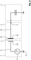
- the capacitive coupler 11 By means of the capacitive coupler 11, it is possible to measure the capacity on the handle 5 of the household appliance 1 with a minimal intervention into the design of the door 4 of the household appliance 1, which eliminates the need for installing the electronic module 7 in the handle 5 of the household appliance 1 or the door 4. There is also no need for installing electric conductors between the door 4 of the household appliance 1 and the housing 2 of the household appliance 1, allowing for a simple integration of the touch sensing system on the handle 4 of the household appliance 1 when it comes to existing household appliances.
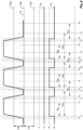
- Fig. 4 shows a time line of signals for the recognition of patterns of one-time user touch interactions with the handle 5 of the door 4.
- the software of the electronic module 7, which is not the subject of the present invention uses a comparison between the measured capacity value C r and the threshold capacity value C pd to sense the touch of the handle 5 of the door 4 provided that the door 4 is closed, wherein the signal S v of the door 4 which takes the value V 0 , sets the value of the signal S r of the handle 5, which serves as the basis for recognising known touch patterns.
- the time interval values Ta, Tb, and Tc are determined in advance and adjusted to the desired user experience with the household appliance.
- the electronic module 7 of the household appliance 1 performs three basic tasks:
- Fig. 4 Described in continuation by referring to Fig. 4 is one of the possible embodiments of the flow of sensing a one-time touch of the handle 5 of the door 4 on the household appliance 1 according to the invention by the user.
- the user touches the handle 5 of the door 4 of the household appliance 1, which reflects in an increase of the measured capacity value C r .
- the user is still touching the handle 5 of the door 4, wherein the said capacity value C r rises above the level for touch sensing on the handle 5 of the door 4 C pd .
- the said software sets the signal S r of the handle 5 to level d 1 (touch) and starts the time measurement of touch duration.
- the said software cancels the current touch pattern sensing process and sets the signal S r of the handle 5 to level d 0 (no touch), after which the household appliance 1 is ready to recognise new touch patterns.
- the user again touches the handle 5 of the door 4 of the household appliance 1, which is reflected in an increase of the measured capacity value C r .
- the user is still touching the handle 5 of the door 4, wherein the measured capacity value C r rises above the capacity level C pd for touch sensing on the handle 5 of the door 4.
- the said software sets the signal S r of the handle 5 to level d 1 (touch) and starts the time measurement of touch duration.
- the user is still touching the handle 5 of the door 4, wherein the measured time value of touch duration is greater than the shortest allowed time interval Ta of touch duration, which meets the first condition for touch pattern recognition.
- the integrated software cancels the current touch pattern recognition process.
- the user stops touching the handle 5 of the door 4 of the household appliance 1.
- the measured capacity value C r drops below the value level for touch sensing capacity C pd .
- the said software sets the signal S r of the handle to level d 0 (no touch), after which the household appliance 1 is ready to recognise new touch patterns.
- the user again touches the handle 5 of the door 4 of the household appliance, which is reflected in an increase in the measured capacity value C r .
- the capacity value C r measured at time t 11 rises above the capacity level C pd for touch sensing on the handle 5 of the door 4.
- the said software sets the signal S r of the handle to level d 1 (touch) and starts the time measurement of touch duration.
- the user is still touching the handle 5 of the door 4, wherein the measured value of touch duration is greater than the shortest time allowed Ta of touch duration, which meets the first condition for touch pattern recognition.
- the user stops touching the handle 5 of the door 4 of the household appliance 1.
- the measured capacity value C r at time t 14 drops below the value level for touch sensing capacity C pd .
- the measured time value of touch duration is less than the longest allowed time interval Tb of touch duration, which also meets the second condition for touch pattern recognition.
- the said software sets the signal S r of the handle to level d 0 (no touch) and starts the measurement of the time interval Tc of response delay, within which it will wait for a potential repeated touch on the handle 5 of the door 4.
- the integrated software detects that the response delay time has timed out. As no repeated touch was sensed on the handle 5 of the door 4 during the response delay time, the last condition for touch pattern recognition is met.
- the said software of the electronic module 7 communicates the information about the recognition of a one-time touch via the communication interface 16to the user interface 15 of the household appliance 1, wherein the latter is ready to recognise new touch patterns.
- Fig. 5 is one of the possible embodiments of the flow of sensing a repeated touch of the handle 5 of the door 4 of the household appliance 1 according to the invention by the user.
- the said software of the electronic module 7 sets the value of signal S r of the handle, which serves as the basis for recognising known touch patterns.
- the user stops touching the handle 5 of the door 4 of the household appliance 1 and, as a result, at time t 4 , the measured capacity value C r drops below the value level of capacity C pd .
- the measured time value of touch duration is less than the longest allowed time interval Tb 1 of touch duration, which also meets the second condition for touch pattern recognition.
- the said software sets the signal S r of the handle to value d 0 (no touch) and starts the measurement of the time interval Tc 1 of response delay, within which it will wait for a potential repeated touch on the handle 5 of the door4.
- the user again touches the handle 5 of the door 4, which results in an increased measured capacity value C r .
- the user is still touching the handle 5 of the door 4, wherein the measured capacity value C r rises above the capacity value C pd for touch sensing on the handle 5 of the door 4.
- the said software sets the signal S r of the handle to value d 1 (touch) and starts the time measurement of touch duration.
- the measured value of the time interval of touch duration is greater than the shortest allowed time interval Ta 2 of touch duration, which meets the next condition for touch pattern recognition.
- the user stops touching the handle 5 of the door 4, wherein at time t 11 , the measured capacity value C r drops below the capacity value C pd for touch sensing on the handle 5 of the door 4.
- the measured value of the time interval of touch duration is less than the longest allowed time interval Tb 2 of touch duration, which meets the next condition for touch pattern recognition.
- the said software sets the signal S r of the handle to value d 0 (no touch) and starts the measurement of the time interval Tc 2 of response delay, within which it will wait for a potential repeated touch on the handle 5 of the door 4.
- the said software transmits via the communication interface 16 information about the recognition of a two-time touch on the module 7 for operating the household appliance 1.
- the system is ready to recognise new touch patterns.
- the user again touches the handle 5 of the door 4 of the household appliance 1, which is reflected in an increased measured capacity value C r .
- the measured capacity value C r rises above the capacity value C pd for touch recognition on the handle 5 of the door 4.
- the said software sets the signal S r of the handle to value d 1 (touch) and starts the measurement of the time interval of touch duration.
- the user stops touching the handle 5 of the door 4, wherein at time t 18 , the measured capacity value C r drops below the capacity value C pd for touch sensing.
- the measured time interval value of touch duration is less than the longest allowed time interval Tb 3 of touch duration, which meets the next condition for touch pattern recognition.
- the said software sets the signal S r of the handle to value d 0 (no touch) and starts the measurement of the time interval Tc 3 of response delay, within which it will wait for a potential repeated touch on the handle 5 of the door 4.
- the described algorithm for touch pattern recognition allows for the recognition of various combinations of consecutive touch counts and touch durations.
- the user starts closing the door 4, wherein the electrodes 10, 12 of the capacitive coupler 11 are fully spaced apart from each other.
- the measured capacity value C r remains constant until the door 4 closes to a degree where the electrodes 10, 12 of the capacity coupler 11 come close to each other.
- the user continues to close the door 4, at time t 8 , they close it to a degree where the measured capacity value C r exceeds the capacity value C po of the threshold for sensing the extent to which the door 4 is open.
- the said software sets the signal S v of the door to value V 0 (closed) and starts the measurement of the time interval Td of system calibration delay.
- the door 4 stops at a final, closed position, wherein the measured capacity value C r stabilises at a value that is normally unequal to the long-term average capacity value C r p, calculated before starting to open the door 4.
- the said software detects that the time of system calibration delay has timed out and starts the system calibration process, which sets the value of the long-term average capacity value C rp to the measured current capacity value C r , and simultaneously recalculates the capacity values C pd , C pr , C po and C pn . If at this moment, the user is not touching the handle of the door 4 of the household appliance 1, the system is ready for touch sensing on the handle 5 of the door 4. In the opposite case, the system remains unresponsive to touch sensing until the user stops touching the handle 5 of the door 4.
- the measured capacity value C r drops.
- the measured capacity value C r drops below the capacity value C pr for initiating system recalibration, wherein the said software starts measuring the time interval Td of delayed system calibration.
Landscapes
- Engineering & Computer Science (AREA)
- Chemical & Material Sciences (AREA)
- Combustion & Propulsion (AREA)
- Mechanical Engineering (AREA)
- General Engineering & Computer Science (AREA)
- Physics & Mathematics (AREA)
- Thermal Sciences (AREA)
- Food Science & Technology (AREA)
- Textile Engineering (AREA)
- Electronic Switches (AREA)
- Switches That Are Operated By Magnetic Or Electric Fields (AREA)
Abstract
A household appliance according to the invention comprises a first electrode (10), which is electrically insulated from any electrically conductive material and arranged in the area above the door aperture, which can be closed by means of a door (4), and a second electrode (12), which is arranged on the side of the said door (4) and spaced from the said first electrode (10). The said electrodes (10, 12) are electrically insulated from each other. Arranged inside a housing (2), in the area above the door aperture, which can be closed by means of the door (4), is an electronic module (7), which comprises an electronic circuit (8) and a controller (9) with integrated software that facilitates capacity measurements, which makes it possible to sense the touch of a user (6). The said handle (5), by means of which it is possible to handle the door (4), is provided as an interface for sensing the touch of the user (6).
Description
- The present invention relates to a household appliance comprising a door handle arranged on the outside of the door of the household appliance, by means of which it is possible to close the interior of the household appliance in relation to the surroundings of the said household appliance, wherein the said door handle comprises at least a part of an electronic system for cooperation between the household appliance and its user.
- The household appliance referred to above is, for example, disclosed in patent applications
WO2020046150A1 ,EP3034948A1 ,WO2020046151A1 . The said known solutions mainly relate to the integration of an electronic touch sensing module on/inside the door handle of the household appliance or inside its door, which significantly limits the design of the handle or door of the said appliance. Moreover, the said known solutions require an electrical connection between the door of the household appliance and a control unit of the said appliance, which cooperates with the said electronic module either via dedicated hinges or electric conductors. The specified characteristics present significant shortcomings that consequently limit the design and usefulness of the household appliance, prevent simple upgrades of existing appliances and complicate the assembly of the final household appliance. The above characteristics also result in higher costs of manufacturing the appliance. - The object of the present invention is to create a household appliance of the type referred to above, which would remedy the shortcomings of known solutions.
- The object according to the present invention is accomplished by the characteristics set forth in the characterising portion of
claim 1. Details of the invention are disclosed in the corresponding sub-claims. - The present invention relates to a household appliance comprising a door handle, which is arranged on the outside of a household appliance door, by means of which it is possible to close the interior of the household appliance in relation to the surroundings of the said household appliance, wherein the said door handle comprises at least an electronic system for cooperation between the household appliance and the user of the handle of the household appliance or to enable the sensing of touch commands of the user. Touch sensing is based on a technology that measures the capacity between the handle of the appliance and/or any other electrically conductive surface on the appliance and the electric potential of earth.
- The invention is further described in detail by way of a non-limiting embodiment and with a reference to the accompanying drawings where
- Fig. 1
- shows a household appliance in a schematic view from the front,
- Fig. 2
- shows a detail of the household appliance from
Fig. 1 in a cross-section from the side, - Fig. 3
- shows an interaction between the household appliance and a user in a schematic view,
- Fig. 4
- shows a signal time line upon a one-time user interaction with the household appliance in a schematic view,
- Fig. 5
- shows a signal time line upon a repeated user interaction with the household appliance in a schematic view, and
- Fig. 6
- shows a detection of the extent to which a door of the household appliance is open or closed in a schematic view.
- A
household appliance 1, such as an oven, refrigerator, dish washer, washing machine, or similar, comprises ahousing 2 with at least onecompartment 3 for receiving the item to be heat-treated, stored, or similar, wherein at least one saidcompartment 3 can be closed by means of a single-section ormulti-section door 4, which is fixed to thehousing 2 of thehousehold appliance 1 by means of hinges, preferably in a way that the saiddoor 4 is easily removable. The saiddoor 4 can be opened or closed by means of ahandle 5, which is connected to thedoor 4. - The said
handle 5 of thedoor 4 of thehousehold appliance 1 is at least partly made of an electrically conductive material, such as metal. The saidhandle 5, by means of which it is possible to handle thedoor 4 of thehousehold appliance 1, is, according to the present invention, also provided as an interface for sensing the touch of auser 6, wherein the saidhandle 5 must be electrically insulated from other electrically conductive elements of thedoor 4 of thehousehold appliance 1 and thehousing 2 of thehousehold appliance 1. - Furthermore, according to the present invention, it is provided that arranged inside the
housing 2 of thehousehold appliance 1, in the area above the door aperture, which can be closed by means of thedoor 4, is anelectronic module 7. The latter is preferably arranged in the area directly above the said door aperture, which can be closed by means of thedoor 4. Furthermore, the saidelectronic module 7 comprises anelectronic circuit 8, acontroller 9 with integrated software that facilitates capacity measurements" which make it possible to sense the touch of the user6, and afirst electrode 10. Theelectronic module 7 is arranged in such a way that thefirst electrode 10 is electrically insulated from thehousing 2 of thehousehold appliance 1 or any electrically conductive material. - A
capacitive coupler 11 comprises thefirst electrode 10, which is connected to theelectronic module 7 and arranged in the area above the door aperture, which can be closed by means of thedoor 4, and asecond electrode 12, which is arranged on the side of the saiddoor 4 and spaced from the saidfirst electrode 10. The saidelectrodes capacitive coupler 11 facilitates indirect measurement of capacity between thehandle 5 of thedoor 4 of thehousehold appliance 1 and the electric potential of the earth in such a way that thefirst electrode 10 of theelectronic module 7 is galvanically isolated from thehandle 5 of thehousehold appliance 1, while thesecond electrode 12 is, by means of aconductor 13, galvanically connected to thehandle 5 of thehousehold appliance 1, which can be touched by theuser 6. - The said
first electrode 10 is formed in such a way that it allows for the compensation of mechanical deviations and structural strain in the manufacture, assembly, and use of thehousehold appliance 1 according to the invention, wherein it is, for example, formed from a flexible material in the manner of a spring. - The said
second electrode 12, which is arranged on the side of the saiddoor 4 of thehousehold appliance 1, is arranged on the upper rear side of thedoor 4 in such a way that it is aligned with the oppositefirst electrode 10 whenever thedoor 4 of thehousehold appliance 1 is in a position that closes the saidcompartment 3. The saidsecond electrode 12 is electrically connected to thehandle 5 of thedoor 4 of thehousehold appliance 1 by means of electric conductors or other electrically conductive parts. At least one of the saidelectrodes household appliance 1. In the presented embodiment, the saidsecond electrode 12 is, by means of aninsulating element 14, electrically insulated from any other electrically conductive part of thehousehold appliance 1. In the presented embodiment, it is provided that theelectrode 12 is inserted into a plastic flange on thedoor 4 of thehousehold appliance 1 by means of a technology for injecting metal parts into plastics. Furthermore, in the preferred embodiment, it is provided that the overlap area ofelectrodes door 4 of thehousehold appliance 1. - To operate the
household appliance 1 according to the invention, auser interface 15 with a screen and suitable markings is further provided. The saiduser interface 15 and the saidelectronic module 7 are connected to each other by means of anelectronic communication interface 16, such as UART, I2C, LIN, SPI, a discrete electric signal, etc. - By means of the
capacitive coupler 11, it is possible to measure the capacity on thehandle 5 of thehousehold appliance 1 with a minimal intervention into the design of thedoor 4 of thehousehold appliance 1, which eliminates the need for installing theelectronic module 7 in thehandle 5 of thehousehold appliance 1 or thedoor 4. There is also no need for installing electric conductors between thedoor 4 of thehousehold appliance 1 and thehousing 2 of thehousehold appliance 1, allowing for a simple integration of the touch sensing system on thehandle 4 of thehousehold appliance 1 when it comes to existing household appliances. -
Fig. 4 shows a time line of signals for the recognition of patterns of one-time user touch interactions with thehandle 5 of thedoor 4. The software of theelectronic module 7, which is not the subject of the present invention, uses a comparison between the measured capacity value Cr and the threshold capacity value Cpd to sense the touch of thehandle 5 of thedoor 4 provided that thedoor 4 is closed, wherein the signal Sv of thedoor 4 which takes the value V0, sets the value of the signal Sr of thehandle 5, which serves as the basis for recognising known touch patterns. - The capacity value
- Cpd constitutes the sum of the long-term average capacity value Crp and constant Ctd,
- Cpr p constitutes the sum of the long-term average capacity value Crp and constant Ctr.
- Ctd, Ctr present constants that are subject to the embodiment and determined in advance,
- and they can optionally be determined or adjusted in real time by means of advanced machine learning algorithms.
- The time interval values Ta, Tb, and Tc are determined in advance and adjusted to the desired user experience with the household appliance. The indicative values of the said time intervals amount to Ta = 50 ms, Tb = 320 ms, Tc = 320 ms.
- The
electronic module 7 of thehousehold appliance 1 according to the invention performs three basic tasks: - a) Performing periodic measurements, i.e. sampling capacity Cr values between the
handle 5 of thedoor 4 and theelectric potential 17 of the earth, wherein the said capacity Cr is preferably measured in a way that the time between two consecutive measurements or the time of sampling is constant and as short as possible, allowing for quick responsiveness and the possibility of additional software processing of the signal, such as a low-pass filter, a median filter, value averaging, etc.; - b) Converting the measured capacity Cr values of the
handle 5 into the signal Sr of status of the user's touch on the door handle and signal Sv of the door status, wherein the software of theelectronic module 7 performs a calculation of the long-term average value of the measured capacity Crp of thehandle 5 of thehousehold appliance 1 in the event when no touch of the user is present; the calculation is performed after each capacity measurement, when the difference between the current capacity value Cr and long-term average capacity value Crp is also calculated; if the said difference is greater than the value of constant Ctd, the value of the signal Sr of touch status is set to value d1, otherwise, the value of the signal is set to value d0; based on the measured capacity value Cr, the status of the door (open or closed) is also determined and used in further signal processing; - c) Recognising known touch patterns, wherein the software of the
electronic module 7, after each conversion of the measured capacity value Cr of thehandle 5 of thedoor 4 of thehousehold appliance 1, checks whether the conditions meet any of the touch patterns determined in advance; The said check of condition adequacy is preferably based on the measurement of time between temporally consecutive changes in signal Sr of the status of touching the handle of the door, for instance the sensing of a one-time touch, wherein the sensing of certain touch patterns on thehandle 5 of thedoor 4 of thehousehold appliance 1 can also take into account the calculated value of the difference between the measured capacity value Cr and long-term average capacity value Crp; whenever a valid touch pattern is sensed, the information about the type of touch pattern is transmitted via theelectronic communication interface 16 to theuser interface 15 of thehousehold appliance 1, wherein it is also enabled to sense the extent to whichdoor 4 of thehousehold appliance 1 is opened or closed and transmit this information via theelectronic communication interface 16 to theuser interface 15 of thehousehold appliance 1. - Described in continuation by referring to
Fig. 4 is one of the possible embodiments of the flow of sensing a one-time touch of thehandle 5 of thedoor 4 on thehousehold appliance 1 according to the invention by the user. - Initially, at time t0, the user touches the
handle 5 of thedoor 4 of thehousehold appliance 1, which reflects in an increase of the measured capacity value Cr. At time t1 the user is still touching thehandle 5 of thedoor 4, wherein the said capacity value Cr rises above the level for touch sensing on thehandle 5 of thedoor 4 Cpd. The said software sets the signal Sr of thehandle 5 to level d1 (touch) and starts the time measurement of touch duration. At time t2, the user stops touching thehandle 5 of thedoor 4, wherein at time t3, the measured capacity value Cr drops below the level of the capacity value Cpd for touch sensing. As the measured time of touch duration is shorter than the shortest allowed time interval Ta of touch duration, which results in failure to meet the first condition for touch pattern recognition, the said software cancels the current touch pattern sensing process and sets the signal Sr of thehandle 5 to level d0 (no touch), after which thehousehold appliance 1 is ready to recognise new touch patterns. - At time t4, the user again touches the
handle 5 of thedoor 4 of thehousehold appliance 1, which is reflected in an increase of the measured capacity value Cr. At time t5, the user is still touching thehandle 5 of thedoor 4, wherein the measured capacity value Cr rises above the capacity level Cpd for touch sensing on thehandle 5 of thedoor 4. The said software sets the signal Sr of thehandle 5 to level d1 (touch) and starts the time measurement of touch duration. At time t6, the user is still touching thehandle 5 of thedoor 4, wherein the measured time value of touch duration is greater than the shortest allowed time interval Ta of touch duration, which meets the first condition for touch pattern recognition. At time t7, the user is still touching thehandle 5 of thedoor 4, wherein the said software detects that the measured time value of touch duration is greater than the longest permitted time interval Tb of touch duration. As the second condition for touch pattern sensing is not met, the integrated software cancels the current touch pattern recognition process. - At time t8, the user stops touching the
handle 5 of thedoor 4 of thehousehold appliance 1. At time t9, the measured capacity value Cr drops below the value level for touch sensing capacity Cpd. The said software sets the signal Sr of the handle to level d0 (no touch), after which thehousehold appliance 1 is ready to recognise new touch patterns. - At time t10, the user again touches the
handle 5 of thedoor 4 of the household appliance, which is reflected in an increase in the measured capacity value Cr. As the user is still touching thehandle 5 of thedoor 4, the capacity value Cr measured at time t11 rises above the capacity level Cpd for touch sensing on thehandle 5 of thedoor 4. The said software sets the signal Sr of the handle to level d1 (touch) and starts the time measurement of touch duration. At time t12, the user is still touching thehandle 5 of thedoor 4, wherein the measured value of touch duration is greater than the shortest time allowed Ta of touch duration, which meets the first condition for touch pattern recognition. - At time t13, the user stops touching the
handle 5 of thedoor 4 of thehousehold appliance 1. The measured capacity value Cr at time t14 drops below the value level for touch sensing capacity Cpd. The measured time value of touch duration is less than the longest allowed time interval Tb of touch duration, which also meets the second condition for touch pattern recognition. The said software sets the signal Sr of the handle to level d0 (no touch) and starts the measurement of the time interval Tc of response delay, within which it will wait for a potential repeated touch on thehandle 5 of thedoor 4. - At time t15, the integrated software detects that the response delay time has timed out. As no repeated touch was sensed on the
handle 5 of thedoor 4 during the response delay time, the last condition for touch pattern recognition is met. The said software of theelectronic module 7 communicates the information about the recognition of a one-time touch via the communication interface 16to theuser interface 15 of thehousehold appliance 1, wherein the latter is ready to recognise new touch patterns. - Furthermore, described in continuation by referring to
Fig. 5 is one of the possible embodiments of the flow of sensing a repeated touch of thehandle 5 of thedoor 4 of thehousehold appliance 1 according to the invention by the user. By comparing the measured capacity value Crto the threshold capacity value Cpd for touch sensing on thehandle 5 of thedoor 4 and under the condition that thedoor 4 is closed and signal Sv of the door has the value V0, the said software of theelectronic module 7 sets the value of signal Sr of the handle, which serves as the basis for recognising known touch patterns. - The capacity value
- Cpd constitutes the sum of the long-term average capacity value Crp and constant Ctd,
- Cpr p constitutes the sum of the long-term average capacity value Crp and constant Ctr.
- Ctd, Ctr present constants that are subject to the embodiment and determined in advance,
- and they can optionally be determined or adjusted in real time by means of advanced machine learning algorithms.
- The time interval values Ta1...Tan, Tb1...Tbn and Tc1...Tcn are normally determined in the system development phase and adjusted based on the desired user experience with the household appliance. With one of the possible embodiments of the
household appliance 1, used, for example, are indicative values Ta1 = Ta2 = Ta3 = 50 ms, Tb1 = Tb2 = Tb3 = 320 ms, Tc1 = Tc2 = Tc3 = 320 ms. - Initially, at time t0, the user touches the
handle 5 of thedoor 4 of thehousehold appliance 1, which results in an increased measured capacity value Cr. At time t1, the user is still touching thehandle 5 of thedoor 4, wherein the measured capacity value Cr rises above the capacity value Cpd, which determines touch sensing on thehandle 5 of thedoor 4. The said software sets the signal Sr of the handle to level d1 (touch) and starts the time measurement of touch duration. At time t2, the user is still touching thehandle 5 of thedoor 4, wherein the measured time value of touch duration is greater than the shortest allowed time interval Ta1 of touch, which meets the first condition for touch pattern recognition. - At time t3, the user stops touching the
handle 5 of thedoor 4 of thehousehold appliance 1 and, as a result, at time t4, the measured capacity value Cr drops below the value level of capacity Cpd. The measured time value of touch duration is less than the longest allowed time interval Tb1 of touch duration, which also meets the second condition for touch pattern recognition. The said software sets the signal Sr of the handle to value d0 (no touch) and starts the measurement of the time interval Tc1 of response delay, within which it will wait for a potential repeated touch on thehandle 5 of the door4. If until the timeout of the time interval Tc1 of response delay no repeated touch occurs, then at time t8, the said software transmits information about the recognition of a one-time touch via thecommunication interface 16 to theuser interface 15, which the user uses to operate thehousehold appliance 1. Thus, the system is ready to recognise new touch patterns. - At time t6, the user again touches the
handle 5 of thedoor 4, which results in an increased measured capacity value Cr. At time t7, the user is still touching thehandle 5 of thedoor 4, wherein the measured capacity value Cr rises above the capacity value Cpd for touch sensing on thehandle 5 of thedoor 4. The said software sets the signal Sr of the handle to value d1 (touch) and starts the time measurement of touch duration. As at time t9 the user is still touching thehandle 5 of thedoor 4, the measured value of the time interval of touch duration is greater than the shortest allowed time interval Ta2 of touch duration, which meets the next condition for touch pattern recognition. - At time t10, the user stops touching the
handle 5 of thedoor 4, wherein at time t11, the measured capacity value Cr drops below the capacity value Cpd for touch sensing on thehandle 5 of thedoor 4. The measured value of the time interval of touch duration is less than the longest allowed time interval Tb2 of touch duration, which meets the next condition for touch pattern recognition. The said software sets the signal Sr of the handle to value d0 (no touch) and starts the measurement of the time interval Tc2 of response delay, within which it will wait for a potential repeated touch on thehandle 5 of thedoor 4. If until the timeout of the time interval Tc2 of response delay no repeated touch occurs, then at time t15 the said software transmits via thecommunication interface 16 information about the recognition of a two-time touch on themodule 7 for operating thehousehold appliance 1. Thus, the system is ready to recognise new touch patterns. - At time t13, the user again touches the
handle 5 of thedoor 4 of thehousehold appliance 1, which is reflected in an increased measured capacity value Cr. As at time t14, the user is still touching thehandle 5 of thedoor 4, the measured capacity value Cr rises above the capacity value Cpd for touch recognition on thehandle 5 of thedoor 4. The said software sets the signal Sr of the handle to value d1 (touch) and starts the measurement of the time interval of touch duration. - As at time t16, the user is still touching the
handle 5 of thedoor 4, the measured time interval value of touch duration is greater than the shortest allowed time interval Ta3 of touch duration, which meets the next condition for touch pattern recognition. - At time t17, the user stops touching the
handle 5 of thedoor 4, wherein at time t18, the measured capacity value Cr drops below the capacity value Cpd for touch sensing. The measured time interval value of touch duration is less than the longest allowed time interval Tb3 of touch duration, which meets the next condition for touch pattern recognition. The said software sets the signal Sr of the handle to value d0 (no touch) and starts the measurement of the time interval Tc3 of response delay, within which it will wait for a potential repeated touch on thehandle 5 of thedoor 4. - At time t20, the said software detects that the time interval Tc3 of response delay has timed out. As no repeated touch was sensed on the
handle 5 of thedoor 4 during the time interval Tc3 of response delay, the last condition for repeated touch pattern recognition is met. via thecommunication interface 16, the said software transmits information about the recognition of a repeated touch to theuser interface 15, which the user uses to operate thehousehold appliance 1. The system is ready to recognise new touch patterns. - The described algorithm for touch pattern recognition allows for the recognition of various combinations of consecutive touch counts and touch durations.
- Shown in continuation by means of
Fig. 6 is a time line of signals in the event that the user opens and closes thedoor 4 of thehousehold appliance 1. The said software of theelectronic module 7 determines the status of door openness by means of comparing the measured capacity value Cr to the threshold capacity value Cpo to detect the extent to which thedoor 4 is open and the threshold capacity value Cpn to detect the adequacy of system operation. - The capacity value
- Cpo constitutes the sum of the long-term average capacity value Crp and constant Cto,
- Cpn constitutes the sum of the long-term average capacity value Crp and constant Ctn,
- Cto, Ctn present constants that are subject to the embodiment and determined in advance and they can optionally be determined or adjusted in real time by means of advanced machine learning algorithms.
- At time t0, the user holds the
handle 5 of thedoor 4 of thehousehold appliance 1, which is reflected in an increased measured capacity value Cr. As a result, at time t1, the measured capacity value Cr rises above the capacity value Cpd for touch sensing on thehandle 5. The said software sets the signal Sr from the handle to value d1 (touch) and starts the time measurement of touch duration. - As at time t2, the user is still holding the
handle 5 of thedoor 4, but has not yet started opening thedoor 4, the measured time value of touch duration is greater than the shortest allowed time interval of touch duration Ta, which meets the first condition for touch pattern recognition. - At time t3, the user starts opening the
door 4, wherein theelectrodes capacitive coupler 11 start moving apart from each other, which results in a drop in the measured capacity value Cr. As the latter drops below the said capacity value Cpd, the said software sets the signal Sr of thehandle 5 to value d0 (no touch) and starts the measurement of the time interval Tc of response delay. - When the user continues to open the
door 4, at time t4, the measured capacity value Cr drops additionally and reaches the capacity value Cpo of the threshold for detecting the extent to which the door is open. The said software sets the signal Sv of the door to value V1 (open) and stops the implementation of the touch pattern recognition algorithm. From this moment on, the system does not allow for touch sensing on thehandle 5 of thedoor 4. - At time t5, the
door 4 is open to a degree where further opening does not cause a drop in the measured value of capacity Cr as theelectrodes capacitive coupler 11 are fully spaced apart. - At time t6, the user starts closing the
door 4, wherein theelectrodes capacitive coupler 11 are fully spaced apart from each other. The measured capacity value Cr remains constant until thedoor 4 closes to a degree where theelectrodes capacity coupler 11 come close to each other. - At time t7, the user closes the
door 4 to a degree where the measured capacity value Cr starts increasing, which is the result of an increasing surface area of overlap between theelectrodes capacitive coupler 11. - As the user continues to close the
door 4, at time t8, they close it to a degree where the measured capacity value Cr exceeds the capacity value Cpo of the threshold for sensing the extent to which thedoor 4 is open. The said software sets the signal Sv of the door to value V0 (closed) and starts the measurement of the time interval Td of system calibration delay. - At time t9, the
door 4 stops at a final, closed position, wherein the measured capacity value Cr stabilises at a value that is normally unequal to the long-term average capacity value Crp, calculated before starting to open thedoor 4. - At time t10, the said software detects that the time of system calibration delay has timed out and starts the system calibration process, which sets the value of the long-term average capacity value Crp to the measured current capacity value Cr, and simultaneously recalculates the capacity values Cpd, Cpr, Cpo and Cpn. If at this moment, the user is not touching the handle of the
door 4 of thehousehold appliance 1, the system is ready for touch sensing on thehandle 5 of thedoor 4. In the opposite case, the system remains unresponsive to touch sensing until the user stops touching thehandle 5 of thedoor 4. - At time t11, when the user stops contact with the
handle 5 of thedoor 4, the measured capacity value Cr drops. At time t12, the measured capacity value Cr drops below the capacity value Cpr for initiating system recalibration, wherein the said software starts measuring the time interval Td of delayed system calibration. - At time t13, the said software detects that the time for delayed system calibration has timed out and initiates the calibration process, which sets the value of the long-term average capacity value Crp to the measured current capacity value Cr. Simultaneously, it recalculates new capacity values Cpd, Cpr, Cpo and Cpn. The system is ready for touch sensing on the
handle 5 of thedoor 4 of the household appliance1.
Claims (7)
- A household appliance comprising a handle of a door, wherein the door is arranged on a housing and the handle is arranged on the outside of the door, wherein it is possible by means of the said door, to close the interior of the household appliance in relation to the surroundings of the household appliance and wherein the said handle of the door comprises at least a part of an electronic system for cooperation of the household appliance with its user, characterised in that it comprises a capacitive coupler (11), which comprises a first electrode (10), which is electrically insulated from any electrically conductive material and arranged in the area above the door aperture, which can be closed by means of the door (4), and a second electrode (12), which is arranged on the side of the said door (4) and spaced from the said first electrode (10), with the said electrodes (10, 12) being electrically insulated from each other, wherein arranged inside the housing (2), in the area above the door aperture, which can be closed by means of the door (4),, is an electronic module (7), comprising an electric circuit (8) and a controller (9) with integrated software that facilitates capacity measurements, which makes it possible to sense the touch of a user (6), and wherein the said handle (5) by means of which it is possible to handle the door (4), is provided as an interface for sensing the touch of the user (6).
- The household appliance according to claim 1, characterised in that the said capacitive coupler (11) allows for an indirect measurement of capacity below the handle (5) of the door (4) and the electric potential of the earth in such a way that the first electrode (10)is galvanically isolated from the handle (5), while the second electrode (12) is, by means of a conductor (13), galvanically connected to the handle (5), which the user can touch (6).
- The household appliance according to claims 1 and 2, characterised in that the said first electrode (10) is formed in such a way that it allows for the compensation of mechanical deviations and structural strain in the manufacture, assembly, and use of the household appliance (1).
- The household appliance according to any of the preceding claims, characterised in that the said second electrode (12) is arranged on the upper rear side of the door (4) in such a way that it is aligned with the opposite first electrode (10) when the door (4) is closed, wherein the second electrode (12) is electrically connected to the handle (5) of the door (4), and simultaneously, by means of an insulating element (14), electrically insulated from any other electrically conductive part of the household appliance (1).
- The household appliance according to claim 3, characterised in that the said first electrode (10) is formed from a flexible material in the manner of a spring.
- The household appliance according to any of the preceding claims, characterised in that the said handle (5) of the door (4) is at least partly made of an electrically conductive material.
- The household appliance according to any of the preceding claims, characterised in that the said handle (5) is electrically insulated from other electrically conductive elements of the door (4) and the housing (2).
Applications Claiming Priority (1)
| Application Number | Priority Date | Filing Date | Title |
|---|---|---|---|
| SI202300162A SI26576A (en) | 2023-12-19 | 2023-12-19 | Household appliance comprising a door handle |
Publications (1)
| Publication Number | Publication Date |
|---|---|
| EP4575320A1 true EP4575320A1 (en) | 2025-06-25 |
Family
ID=93841049
Family Applications (1)
| Application Number | Title | Priority Date | Filing Date |
|---|---|---|---|
| EP24217638.6A Withdrawn EP4575320A1 (en) | 2023-12-19 | 2024-12-05 | Household appliance comprising a door handle |
Country Status (3)
| Country | Link |
|---|---|
| EP (1) | EP4575320A1 (en) |
| CN (1) | CN120175160A (en) |
| SI (1) | SI26576A (en) |
Citations (6)
| Publication number | Priority date | Publication date | Assignee | Title |
|---|---|---|---|---|
| DE10138885A1 (en) * | 2001-08-08 | 2003-02-20 | Bsh Bosch Siemens Hausgeraete | Household appliance has capacitative door handle with control circuit capable of detecting the touch, to switch on internal lighting |
| DE102012222152A1 (en) * | 2012-12-04 | 2014-06-05 | BSH Bosch und Siemens Hausgeräte GmbH | Household appliance, particularly cooking appliance, such as baking oven, has door and door detection device for detecting door state of door, where door detection device comprises capacitive sensor, whose moving electrode is door |
| EP3034948A1 (en) | 2014-12-19 | 2016-06-22 | Electrolux Appliances Aktiebolag | Oven door and oven comprising an oven door |
| EP3136002A1 (en) * | 2015-08-27 | 2017-03-01 | Electrolux Appliances Aktiebolag | Door handle for a door of a domestic appliance |
| WO2020046150A1 (en) | 2018-08-29 | 2020-03-05 | Amica S.A. | Oven with a touch door handle |
| WO2020046151A1 (en) | 2018-08-29 | 2020-03-05 | Amica S.A. | Communication system between the door and the body of the oven |
-
2023
- 2023-12-19 SI SI202300162A patent/SI26576A/en active IP Right Grant
-
2024
- 2024-11-29 CN CN202411731762.9A patent/CN120175160A/en active Pending
- 2024-12-05 EP EP24217638.6A patent/EP4575320A1/en not_active Withdrawn
Patent Citations (6)
| Publication number | Priority date | Publication date | Assignee | Title |
|---|---|---|---|---|
| DE10138885A1 (en) * | 2001-08-08 | 2003-02-20 | Bsh Bosch Siemens Hausgeraete | Household appliance has capacitative door handle with control circuit capable of detecting the touch, to switch on internal lighting |
| DE102012222152A1 (en) * | 2012-12-04 | 2014-06-05 | BSH Bosch und Siemens Hausgeräte GmbH | Household appliance, particularly cooking appliance, such as baking oven, has door and door detection device for detecting door state of door, where door detection device comprises capacitive sensor, whose moving electrode is door |
| EP3034948A1 (en) | 2014-12-19 | 2016-06-22 | Electrolux Appliances Aktiebolag | Oven door and oven comprising an oven door |
| EP3136002A1 (en) * | 2015-08-27 | 2017-03-01 | Electrolux Appliances Aktiebolag | Door handle for a door of a domestic appliance |
| WO2020046150A1 (en) | 2018-08-29 | 2020-03-05 | Amica S.A. | Oven with a touch door handle |
| WO2020046151A1 (en) | 2018-08-29 | 2020-03-05 | Amica S.A. | Communication system between the door and the body of the oven |
Also Published As
| Publication number | Publication date |
|---|---|
| SI26576A (en) | 2025-06-30 |
| CN120175160A (en) | 2025-06-20 |
Similar Documents
| Publication | Publication Date | Title |
|---|---|---|
| US8720279B2 (en) | Object detection device with variable sensitivity electric field measurement circuit | |
| US8796575B2 (en) | Proximity switch assembly having ground layer | |
| EP1999848B1 (en) | Door position sensor | |
| EP3023567B1 (en) | Operation detecting device of opening and closing body for vehicle | |
| JP6121397B2 (en) | Measuring device and method for detection of proximity to a portable device | |
| US9945160B2 (en) | Vehicle door locking system | |
| US8217666B2 (en) | Capacitance detection apparatus | |
| JP2012129762A (en) | Capacitance detection device and contact detection sensor | |
| US20180265043A1 (en) | Proximity switch and humidity sensor assembly | |
| CN108376032B (en) | Capacitive touch sensing unit computation power reduction using keypad electrode crosstalk | |
| CN107503416B (en) | Detection circuit of closestool and detection method thereof | |
| CN105530007A (en) | Directional proximity switch assembly | |
| CN104137419A (en) | Capacitive sensor arrangement for switching a door opening in a motor vehicle and associated method | |
| CN105420995A (en) | Cover opening and closing detection method of clothes processing equipment and clothes processing equipment thereof | |
| CN111026296A (en) | Response control method, device and electrical appliance for touch key | |
| CN112227013A (en) | Washing machine and key control method | |
| CN111578439A (en) | Wet hand detection device, drive-by-wire ware and air conditioner of touch button | |
| CN114270708B (en) | Method for setting sampling frequency of capacitive touch switch | |
| CN113475868B (en) | Control method of intelligent mirror cabinet and intelligent mirror cabinet | |
| JP6183042B2 (en) | Touch sensor | |
| CN113445259B (en) | Key structure, key structure control method and washing machine | |
| CN120175160A (en) | Household appliances including door handles | |
| CN112981863A (en) | Washing machine and washing machine control method | |
| CN105549735A (en) | Control method, control device and electronic device | |
| CN222599024U (en) | Capacitive handle sensor integrating pressure detection |
Legal Events
| Date | Code | Title | Description |
|---|---|---|---|
| PUAI | Public reference made under article 153(3) epc to a published international application that has entered the european phase |
Free format text: ORIGINAL CODE: 0009012 |
|
| STAA | Information on the status of an ep patent application or granted ep patent |
Free format text: STATUS: THE APPLICATION HAS BEEN PUBLISHED |
|
| AK | Designated contracting states |
Kind code of ref document: A1 Designated state(s): AL AT BE BG CH CY CZ DE DK EE ES FI FR GB GR HR HU IE IS IT LI LT LU LV MC ME MK MT NL NO PL PT RO RS SE SI SK SM TR |
|
| STAA | Information on the status of an ep patent application or granted ep patent |
Free format text: STATUS: THE APPLICATION HAS BEEN WITHDRAWN |
|
| 18W | Application withdrawn |
Effective date: 20251223 |