EP4575294A1 - Earthquake-resistant expansion joint for ducts - Google Patents
Earthquake-resistant expansion joint for ducts Download PDFInfo
- Publication number
- EP4575294A1 EP4575294A1 EP24215670.1A EP24215670A EP4575294A1 EP 4575294 A1 EP4575294 A1 EP 4575294A1 EP 24215670 A EP24215670 A EP 24215670A EP 4575294 A1 EP4575294 A1 EP 4575294A1
- Authority
- EP
- European Patent Office
- Prior art keywords
- angled
- pipe
- rigid
- expansion joint
- curved
- Prior art date
- Legal status (The legal status is an assumption and is not a legal conclusion. Google has not performed a legal analysis and makes no representation as to the accuracy of the status listed.)
- Granted
Links
Images

Classifications
-
- F—MECHANICAL ENGINEERING; LIGHTING; HEATING; WEAPONS; BLASTING
- F16—ENGINEERING ELEMENTS AND UNITS; GENERAL MEASURES FOR PRODUCING AND MAINTAINING EFFECTIVE FUNCTIONING OF MACHINES OR INSTALLATIONS; THERMAL INSULATION IN GENERAL
- F16L—PIPES; JOINTS OR FITTINGS FOR PIPES; SUPPORTS FOR PIPES, CABLES OR PROTECTIVE TUBING; MEANS FOR THERMAL INSULATION IN GENERAL
- F16L51/00—Expansion-compensation arrangements for pipe-lines
- F16L51/04—Expansion-compensation arrangements for pipe-lines making use of bends, e.g. lyre-shaped
-
- F—MECHANICAL ENGINEERING; LIGHTING; HEATING; WEAPONS; BLASTING
- F16—ENGINEERING ELEMENTS AND UNITS; GENERAL MEASURES FOR PRODUCING AND MAINTAINING EFFECTIVE FUNCTIONING OF MACHINES OR INSTALLATIONS; THERMAL INSULATION IN GENERAL
- F16L—PIPES; JOINTS OR FITTINGS FOR PIPES; SUPPORTS FOR PIPES, CABLES OR PROTECTIVE TUBING; MEANS FOR THERMAL INSULATION IN GENERAL
- F16L27/00—Adjustable joints; Joints allowing movement
- F16L27/08—Adjustable joints; Joints allowing movement allowing adjustment or movement only about the axis of one pipe
- F16L27/0804—Adjustable joints; Joints allowing movement allowing adjustment or movement only about the axis of one pipe the fluid passing axially from one joint element to another
- F16L27/0837—Adjustable joints; Joints allowing movement allowing adjustment or movement only about the axis of one pipe the fluid passing axially from one joint element to another the joint elements being bends
- F16L27/0845—Adjustable joints; Joints allowing movement allowing adjustment or movement only about the axis of one pipe the fluid passing axially from one joint element to another the joint elements being bends forming an angle of 90 degrees
-
- F—MECHANICAL ENGINEERING; LIGHTING; HEATING; WEAPONS; BLASTING
- F16—ENGINEERING ELEMENTS AND UNITS; GENERAL MEASURES FOR PRODUCING AND MAINTAINING EFFECTIVE FUNCTIONING OF MACHINES OR INSTALLATIONS; THERMAL INSULATION IN GENERAL
- F16L—PIPES; JOINTS OR FITTINGS FOR PIPES; SUPPORTS FOR PIPES, CABLES OR PROTECTIVE TUBING; MEANS FOR THERMAL INSULATION IN GENERAL
- F16L27/00—Adjustable joints; Joints allowing movement
- F16L27/08—Adjustable joints; Joints allowing movement allowing adjustment or movement only about the axis of one pipe
- F16L27/0861—Arrangements of joints with one another and with pipes or hoses
-
- F—MECHANICAL ENGINEERING; LIGHTING; HEATING; WEAPONS; BLASTING
- F16—ENGINEERING ELEMENTS AND UNITS; GENERAL MEASURES FOR PRODUCING AND MAINTAINING EFFECTIVE FUNCTIONING OF MACHINES OR INSTALLATIONS; THERMAL INSULATION IN GENERAL
- F16L—PIPES; JOINTS OR FITTINGS FOR PIPES; SUPPORTS FOR PIPES, CABLES OR PROTECTIVE TUBING; MEANS FOR THERMAL INSULATION IN GENERAL
- F16L55/00—Devices or appurtenances for use in, or in connection with, pipes or pipe systems
- F16L55/04—Devices damping pulsations or vibrations in fluids
- F16L55/043—Devices damping pulsations or vibrations in fluids specially adapted for protecting instruments from water hammer or vibrations
Definitions
- the present invention concerns expansion joints for ducts and in particular it concerns a new earthquake-resistant expansion joint for ducts.
- Hydraulic systems more specifically water systems, usually comprise expansion vessels intended to prevent the so-called water hammer following a sudden shutdown of the demand of circulating fluid, and partly also to maintain a constant pressure in the system in case of temperature changes.
- Main pipelines which serve several buildings, are made of a rigid material, usually stainless steel.
- earthquake-resistant expansion joints for ducts are used, at regular intervals or at the buildings.
- Said joints are designed to absorb sudden loads resulting from earthquakes in seismic areas, and to eliminate stress on the line, thus allowing the systems to move in six different directions integrally with the structures and ensuring their continuous and uninterrupted operation.
- Earthquake-resistant expansion joints are made up of several pipe sections assembled together to form a generically U- or V-shaped unit, in which each of the two ends of said U or V shape comprises a section of rigid curved pipe suited to be connected to one of the two generically coaxial pipe sections, while the two parallel sections of said U shape, or the diverging sections of the V shape, are flexible.
- the vertex portion of the U shape or V shape consists of a rigid curved pipe section.
- the earthquake-resistant expansion joints used at present have several drawbacks.
- One object of the invention is to provide a new joint whose production time is reduced.
- Another object of the invention is to provide a new joint whose production costs are reduced.
- Another object of the invention is to reduce the production costs of joints having the same diameter and flow rate but capable of absorbing movement to a greater or lesser extent.
- Another object of the present invention is to improve the storage conditions of the joints for which there is less demand and to reduce the space they occupy in the warehouse.
- the new earthquake-resistant expansion joint comprising two flexible pipes, one rigid pipe, four angled or curved pipe fittings, and six grooved rigid joints.
- the flexible pipes, the rigid pipe and the angled or curved pipe fittings all have their ends shaped with an annular projection that is concentric with the end itself. Said annular projections at the end of the flexible pipes, of the rigid pipe and of the angled or curved pipe fittings are suitable for connection with a grooved rigid joint.
- the flexible pipes, the rigid pipe and the angled or curved pipe fittings listed above are arranged in the following sequence: angled or curved pipe fitting, flexible pipe, angled or curved pipe fitting, rigid pipe, angled or curved pipe fitting, flexible pipe, angled or curved pipe fitting so as to form a U shape or a V shape.
- Each end of each pipe is joined and connected to the end of the adjacent angled or curved pipe fitting by means of a grooved rigid joint.
- Each grooved rigid joint comprises two semicircular segments that can be coupled together by means of screws and nuts so as to form a complete circle.
- each semicircular segment of a grooved rigid joint is provided with two parallel grooves suited to accommodate and retain said annular projections of the ends of the pipes and of the angled or curved pipe fittings.
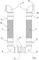
- Figure 1 shows the new earthquake-resistant expansion joint when assembled, while Figure 2 shows the various parts separated but near one another, except for the grooved rigid joints (G).
- the new earthquake-resistant expansion joint comprises two flexible pipes (F), one rigid pipe (D), four angled (R) or curved pipe fittings, six grooved rigid joints (G).
- Each flexible pipe (F) comprises, in turn, two rigid connection sections (F1) joined by a flexible section (F2).
- the free ends of said two connection sections (F1) are externally provided with an annular projection (Fr) that is concentric with the end itself.
- Said rigid pipe (D) consists of a section of non-flexible pipe.
- the ends of said rigid pipe (D) are externally provided with an annular projection (Dr) that is concentric with the end itself.
- Said angled (R) or curved pipe fittings consist of portions whose connection ends are angled with respect to each other.
- the ends of each angled (R) or curved pipe fitting are externally provided with an annular projection (Rr) that is concentric with the end itself.
- the flexible pipes (F), the rigid pipe (D) and the angled (R) or curved pipe fittings are arranged as shown in Figure 2 .
- the example shows angled (R) or curved pipe fittings whose two ends are arranged at 90° with respect to each other. Consequently, the new earthquake-resistant expansion joint assumes the generic shape of a U.
- Said joint is capable of absorbing expansion both in the direction of the plane defined by said pipes and in the direction of the plane orthogonal to it.
- the new earthquake-resistant expansion joint made up as described above offers considerable advantages.
- the new expansion joint allows inspection and maintenance of each of its individual sections.
Landscapes
- Engineering & Computer Science (AREA)
- General Engineering & Computer Science (AREA)
- Mechanical Engineering (AREA)
- Joints Allowing Movement (AREA)
Abstract
Description
- The present invention concerns expansion joints for ducts and in particular it concerns a new earthquake-resistant expansion joint for ducts.
- Hydraulic systems, more specifically water systems, usually comprise expansion vessels intended to prevent the so-called water hammer following a sudden shutdown of the demand of circulating fluid, and partly also to maintain a constant pressure in the system in case of temperature changes.
- Main pipelines, which serve several buildings, are made of a rigid material, usually stainless steel.
- In case of ground settlement, building settlement or earthquakes, these pipelines are subject to movements and displacements along one or more axes as well as to rotary movements.
- To compensate for said movements and displacements, earthquake-resistant expansion joints for ducts are used, at regular intervals or at the buildings.
- Said joints are designed to absorb sudden loads resulting from earthquakes in seismic areas, and to eliminate stress on the line, thus allowing the systems to move in six different directions integrally with the structures and ensuring their continuous and uninterrupted operation.
- Earthquake-resistant expansion joints are made up of several pipe sections assembled together to form a generically U- or V-shaped unit, in which each of the two ends of said U or V shape comprises a section of rigid curved pipe suited to be connected to one of the two generically coaxial pipe sections, while the two parallel sections of said U shape, or the diverging sections of the V shape, are flexible.
- The vertex portion of the U shape or V shape consists of a rigid curved pipe section.
- All of said pipe sections, rigid or flexible, are actually joined together in such a way that they cannot be separated, that is, by welding or screwing.
- The earthquake-resistant expansion joints used at present have several drawbacks.
- Joining the different pipe sections by welding requires time, skilled labour and specific equipment.
- Joining the different pipe sections by screwing them together requires time and the use of sealing gaskets on the threads, and does not guarantee tightness over time and under stress conditions.
- If maintenance on any part of the joints is needed, they must be completely disconnected from the system in which they are installed.
- If joints with the same diameter but capable of absorbing movement to a greater or lesser extent are needed, meaning with parallel sections of said U shape or diverging sections of the V shape, all parts must be joined during production and the resulting product is a single object and cannot be modified.
- In order to overcome all the drawbacks mentioned above, a new type of earthquake-resistant expansion joint has been designed and manufactured.
- One object of the invention is to provide a new joint whose production time is reduced.
- Another object of the invention is to provide a new joint whose production costs are reduced.
- Another object of the invention is to reduce the production costs of joints having the same diameter and flow rate but capable of absorbing movement to a greater or lesser extent.
- Another object of the present invention is to improve the storage conditions of the joints for which there is less demand and to reduce the space they occupy in the warehouse.
- These and other direct and complementary objects are achieved by the new earthquake-resistant expansion joint comprising two flexible pipes, one rigid pipe, four angled or curved pipe fittings, and six grooved rigid joints.
- The flexible pipes, the rigid pipe and the angled or curved pipe fittings all have their ends shaped with an annular projection that is concentric with the end itself. Said annular projections at the end of the flexible pipes, of the rigid pipe and of the angled or curved pipe fittings are suitable for connection with a grooved rigid joint.
- The flexible pipes, the rigid pipe and the angled or curved pipe fittings listed above are arranged in the following sequence: angled or curved pipe fitting, flexible pipe, angled or curved pipe fitting, rigid pipe, angled or curved pipe fitting, flexible pipe, angled or curved pipe fitting so as to form a U shape or a V shape.
- Each end of each pipe is joined and connected to the end of the adjacent angled or curved pipe fitting by means of a grooved rigid joint.
- Each grooved rigid joint comprises two semicircular segments that can be coupled together by means of screws and nuts so as to form a complete circle.
- The concave part of each semicircular segment of a grooved rigid joint is provided with two parallel grooves suited to accommodate and retain said annular projections of the ends of the pipes and of the angled or curved pipe fittings.
- The characteristics of the new earthquake- resistant expansion joint are better clarified in the following description, making reference to the drawings, which are attached by way of non-limiting example.
-
Figure 1 shows the new earthquake-resistant expansion joint when assembled, whileFigure 2 shows the various parts separated but near one another, except for the grooved rigid joints (G). - The new earthquake-resistant expansion joint comprises two flexible pipes (F), one rigid pipe (D), four angled (R) or curved pipe fittings, six grooved rigid joints (G).
- Each flexible pipe (F) comprises, in turn, two rigid connection sections (F1) joined by a flexible section (F2). The free ends of said two connection sections (F1) are externally provided with an annular projection (Fr) that is concentric with the end itself.
- Said rigid pipe (D) consists of a section of non-flexible pipe. The ends of said rigid pipe (D) are externally provided with an annular projection (Dr) that is concentric with the end itself.
- Said angled (R) or curved pipe fittings consist of portions whose connection ends are angled with respect to each other. The ends of each angled (R) or curved pipe fitting are externally provided with an annular projection (Rr) that is concentric with the end itself.
- The flexible pipes (F), the rigid pipe (D) and the angled (R) or curved pipe fittings are arranged as shown in
Figure 2 . - The ends of the various pipes (F, D) and of the angled pipe fittings (R) are brought near each other, and a grooved rigid joint (G) is applied to each pair of adjacent ends in such a way as to obtain the assembly shown in
Figure 1 . - The example shows angled (R) or curved pipe fittings whose two ends are arranged at 90° with respect to each other. Consequently, the new earthquake-resistant expansion joint assumes the generic shape of a U.
- Said joint is capable of absorbing expansion both in the direction of the plane defined by said pipes and in the direction of the plane orthogonal to it.
- An equivalent solution is represented by the use of angled (R) or curved pipe fittings whose two ends are arranged at 120° with respect to each other, so that the new earthquake-resistant expansion joint assumes the generic shape of a V.
- The new earthquake-resistant expansion joint made up as described above offers considerable advantages.
- The production of each expansion joint takes a short time.
- The production of each expansion joint does not require the use of special tools or equipment.
- The production of each expansion joint requires the simple mechanical connection of parts.
- The production of expansion joints having the same diameter and flow rate but capable of absorbing different movements requires the simple assembly of the same parts with flexible pipes (F) of different lengths.
- It is possible to replace just one part of the new expansion joint instead of replacing the entire expansion joint.
- The new expansion joint allows inspection and maintenance of each of its individual sections.
- These are the schematic outlines that are sufficient for the expert in the art to carry out the invention, consequently, on practical application variants may be obtained that do not affect the substance of the innovative concept introduced herewith.
- Therefore, with reference to the above description and the attached drawings, the following claims are made.
Claims (3)
- Earthquake-resistant expansion joint for ducts, characterized in that it comprises two flexible pipes (F), one rigid pipe (D), four angled (R) or curved pipe fittings, six grooved rigid joints (G), and wherein said flexible pipes, said rigid pipe, said angled or curved pipe fittings have their ends shaped with an annular projection (Fr, Dr, Rr) that is concentric with the end itself, and wherein said flexible pipes (F), said rigid pipe (D), said angled (R) or curved pipe fittings are arranged according to the following sequence: angled (R) or curved pipe fitting, flexible pipe (F), angled (R) or curved pipe fitting, rigid pipe (D), angled (R) or curved fitting, flexible pipe (F), angled (R) or curved fitting according to a generically U-shaped or V-shaped arrangement, and wherein the end of each pipe (F, D) is joined and connected to the end of the adjacent angled (R) or curved pipe fitting by means of a grooved rigid joint (G).
- Earthquake-resistant expansion joint according to claim 1, characterized in that said angled (R) or curved pipe fittings are at right angles, with the two ends arranged at 90° with respect to each other.
- Earthquake-resistant expansion joint according to claim 1, characterized in that each of said angled (R) or curved pipe fittings has its two ends arranged at 120° with respect to each other.
Applications Claiming Priority (1)
| Application Number | Priority Date | Filing Date | Title |
|---|---|---|---|
| IT102023000027048A IT202300027048A1 (en) | 2023-12-18 | 2023-12-18 | ANTI-SEISMIC EXPANSION JOINT FOR PIPES |
Publications (3)
| Publication Number | Publication Date |
|---|---|
| EP4575294A1 true EP4575294A1 (en) | 2025-06-25 |
| EP4575294C0 EP4575294C0 (en) | 2026-02-18 |
| EP4575294B1 EP4575294B1 (en) | 2026-02-18 |
Family
ID=90123252
Family Applications (1)
| Application Number | Title | Priority Date | Filing Date |
|---|---|---|---|
| EP24215670.1A Active EP4575294B1 (en) | 2023-12-18 | 2024-11-27 | Earthquake-resistant expansion joint for ducts |
Country Status (2)
| Country | Link |
|---|---|
| EP (1) | EP4575294B1 (en) |
| IT (1) | IT202300027048A1 (en) |
Citations (3)
| Publication number | Priority date | Publication date | Assignee | Title |
|---|---|---|---|---|
| JP4477984B2 (en) * | 2004-10-08 | 2010-06-09 | 株式会社竹中工務店 | Seismic isolation joint and seismic isolation piping structure |
| CN102182896A (en) * | 2011-04-19 | 2011-09-14 | 冯亿生 | Practical vibration isolating mechanism |
| EP4148314A1 (en) * | 2021-06-23 | 2023-03-15 | The Metraflex Company | Expansion loop for copper piping system |
-
2023
- 2023-12-18 IT IT102023000027048A patent/IT202300027048A1/en unknown
-
2024
- 2024-11-27 EP EP24215670.1A patent/EP4575294B1/en active Active
Patent Citations (3)
| Publication number | Priority date | Publication date | Assignee | Title |
|---|---|---|---|---|
| JP4477984B2 (en) * | 2004-10-08 | 2010-06-09 | 株式会社竹中工務店 | Seismic isolation joint and seismic isolation piping structure |
| CN102182896A (en) * | 2011-04-19 | 2011-09-14 | 冯亿生 | Practical vibration isolating mechanism |
| EP4148314A1 (en) * | 2021-06-23 | 2023-03-15 | The Metraflex Company | Expansion loop for copper piping system |
Also Published As
| Publication number | Publication date |
|---|---|
| IT202300027048A1 (en) | 2025-06-18 |
| EP4575294C0 (en) | 2026-02-18 |
| EP4575294B1 (en) | 2026-02-18 |
Similar Documents
| Publication | Publication Date | Title |
|---|---|---|
| JP5628318B2 (en) | Flexible assembly for sprinkler | |
| US5803506A (en) | Flexible pipe loop | |
| CA2789398C (en) | Coupling having angularly oriented key surfaces | |
| US4108476A (en) | Precompressed piping system for handling cryogenic fluid | |
| US7722087B2 (en) | Coupling having angularly oriented cavity | |
| US3464722A (en) | Pipe coupling having segmented clamping means | |
| KR101318774B1 (en) | Ball type expansion joint | |
| CN211550838U (en) | Expansion joint | |
| EP4575294B1 (en) | Earthquake-resistant expansion joint for ducts | |
| US10458575B2 (en) | Flexible pipe loop | |
| AU2018238303B2 (en) | Positive lock system for restrained joints of ductile iron spun pipes and fittings | |
| US5580102A (en) | Pipe support and pipeline therewith | |
| RU2087786C1 (en) | Light-weight funnel-shaped nondetachable connection | |
| US20120049515A1 (en) | Boltless Pipe Joint Assembly | |
| CN113154154A (en) | Fire-fighting pipe fitting and installation method thereof | |
| KR200368634Y1 (en) | Expansion joint | |
| SU1516708A1 (en) | Device for connecting non-metal tubes with smooth ends | |
| US20230349493A1 (en) | Connector assembly | |
| Carter | A comparison of mechanical grooving and flanging-pipe joining techniques: water and wastewater | |
| WO2015190947A1 (en) | Tool-free self-tightening coupling | |
| OA19798A (en) | Positive lock system for restrained joints of ductile iron spun pipes and fittings. | |
| AU2010346460B2 (en) | Coupling having angularly oriented key surfaces | |
| EP0082846A1 (en) | Fluid flow ductwork | |
| JPH0143878B2 (en) | ||
| KR20060007724A (en) | Expansion joint |
Legal Events
| Date | Code | Title | Description |
|---|---|---|---|
| PUAI | Public reference made under article 153(3) epc to a published international application that has entered the european phase |
Free format text: ORIGINAL CODE: 0009012 |
|
| STAA | Information on the status of an ep patent application or granted ep patent |
Free format text: STATUS: THE APPLICATION HAS BEEN PUBLISHED |
|
| AK | Designated contracting states |
Kind code of ref document: A1 Designated state(s): AL AT BE BG CH CY CZ DE DK EE ES FI FR GB GR HR HU IE IS IT LI LT LU LV MC ME MK MT NL NO PL PT RO RS SE SI SK SM TR |
|
| STAA | Information on the status of an ep patent application or granted ep patent |
Free format text: STATUS: REQUEST FOR EXAMINATION WAS MADE |
|
| GRAP | Despatch of communication of intention to grant a patent |
Free format text: ORIGINAL CODE: EPIDOSNIGR1 |
|
| STAA | Information on the status of an ep patent application or granted ep patent |
Free format text: STATUS: GRANT OF PATENT IS INTENDED |
|
| 17P | Request for examination filed |
Effective date: 20250911 |
|
| RIC1 | Information provided on ipc code assigned before grant |
Ipc: F16L 27/08 20060101AFI20250917BHEP Ipc: F16L 51/04 20060101ALI20250917BHEP |
|
| INTG | Intention to grant announced |
Effective date: 20251001 |
|
| GRAS | Grant fee paid |
Free format text: ORIGINAL CODE: EPIDOSNIGR3 |
|
| GRAA | (expected) grant |
Free format text: ORIGINAL CODE: 0009210 |
|
| STAA | Information on the status of an ep patent application or granted ep patent |
Free format text: STATUS: THE PATENT HAS BEEN GRANTED |
|
| RAP1 | Party data changed (applicant data changed or rights of an application transferred) |
Owner name: PROSYSTEM GROUP SRL |
|
| AK | Designated contracting states |
Kind code of ref document: B1 Designated state(s): AL AT BE BG CH CY CZ DE DK EE ES FI FR GB GR HR HU IE IS IT LI LT LU LV MC ME MK MT NL NO PL PT RO RS SE SI SK SM TR |
|
| REG | Reference to a national code |
Ref country code: CH Ref legal event code: F10 Free format text: ST27 STATUS EVENT CODE: U-0-0-F10-F00 (AS PROVIDED BY THE NATIONAL OFFICE) Effective date: 20260218 Ref country code: GB Ref legal event code: FG4D |
|
| REG | Reference to a national code |
Ref country code: DE Ref legal event code: R096 Ref document number: 602024002668 Country of ref document: DE |
|
| REG | Reference to a national code |
Ref country code: IE Ref legal event code: FG4D |
|
| U01 | Request for unitary effect filed |
Effective date: 20260305 |
|
| U07 | Unitary effect registered |
Designated state(s): AT BE BG DE DK EE FI FR IT LT LU LV MT NL PT RO SE SI Effective date: 20260331 |
|
| PG25 | Lapsed in a contracting state [announced via postgrant information from national office to epo] |
Ref country code: RS Free format text: LAPSE BECAUSE OF FAILURE TO SUBMIT A TRANSLATION OF THE DESCRIPTION OR TO PAY THE FEE WITHIN THE PRESCRIBED TIME-LIMIT Effective date: 20260518 |
|
| PG25 | Lapsed in a contracting state [announced via postgrant information from national office to epo] |
Ref country code: ES Free format text: LAPSE BECAUSE OF FAILURE TO SUBMIT A TRANSLATION OF THE DESCRIPTION OR TO PAY THE FEE WITHIN THE PRESCRIBED TIME-LIMIT Effective date: 20260218 |
|
| PG25 | Lapsed in a contracting state [announced via postgrant information from national office to epo] |
Ref country code: PL Free format text: LAPSE BECAUSE OF FAILURE TO SUBMIT A TRANSLATION OF THE DESCRIPTION OR TO PAY THE FEE WITHIN THE PRESCRIBED TIME-LIMIT Effective date: 20260218 |
|
| PG25 | Lapsed in a contracting state [announced via postgrant information from national office to epo] |
Ref country code: GR Free format text: LAPSE BECAUSE OF FAILURE TO SUBMIT A TRANSLATION OF THE DESCRIPTION OR TO PAY THE FEE WITHIN THE PRESCRIBED TIME-LIMIT Effective date: 20260519 |
|
| PG25 | Lapsed in a contracting state [announced via postgrant information from national office to epo] |
Ref country code: NO Free format text: LAPSE BECAUSE OF FAILURE TO SUBMIT A TRANSLATION OF THE DESCRIPTION OR TO PAY THE FEE WITHIN THE PRESCRIBED TIME-LIMIT Effective date: 20260518 |
|
| PG25 | Lapsed in a contracting state [announced via postgrant information from national office to epo] |
Ref country code: HR Free format text: LAPSE BECAUSE OF FAILURE TO SUBMIT A TRANSLATION OF THE DESCRIPTION OR TO PAY THE FEE WITHIN THE PRESCRIBED TIME-LIMIT Effective date: 20260218 |
|
| PG25 | Lapsed in a contracting state [announced via postgrant information from national office to epo] |
Ref country code: IS Free format text: LAPSE BECAUSE OF FAILURE TO SUBMIT A TRANSLATION OF THE DESCRIPTION OR TO PAY THE FEE WITHIN THE PRESCRIBED TIME-LIMIT Effective date: 20260618 |