EP4575280A1 - Modular valve assembly - Google Patents
Modular valve assembly Download PDFInfo
- Publication number
- EP4575280A1 EP4575280A1 EP24222515.9A EP24222515A EP4575280A1 EP 4575280 A1 EP4575280 A1 EP 4575280A1 EP 24222515 A EP24222515 A EP 24222515A EP 4575280 A1 EP4575280 A1 EP 4575280A1
- Authority
- EP
- European Patent Office
- Prior art keywords
- valve
- openings
- piston
- assembly
- hub
- Prior art date
- Legal status (The legal status is an assumption and is not a legal conclusion. Google has not performed a legal analysis and makes no representation as to the accuracy of the status listed.)
- Pending
Links
Images



Classifications
-
- F—MECHANICAL ENGINEERING; LIGHTING; HEATING; WEAPONS; BLASTING
- F16—ENGINEERING ELEMENTS AND UNITS; GENERAL MEASURES FOR PRODUCING AND MAINTAINING EFFECTIVE FUNCTIONING OF MACHINES OR INSTALLATIONS; THERMAL INSULATION IN GENERAL
- F16K—VALVES; TAPS; COCKS; ACTUATING-FLOATS; DEVICES FOR VENTING OR AERATING
- F16K11/00—Multiple-way valves, e.g. mixing valves; Pipe fittings incorporating such valves
- F16K11/02—Multiple-way valves, e.g. mixing valves; Pipe fittings incorporating such valves with all movable sealing faces moving as one unit
- F16K11/022—Multiple-way valves, e.g. mixing valves; Pipe fittings incorporating such valves with all movable sealing faces moving as one unit comprising a deformable member
- F16K11/025—Multiple-way valves, e.g. mixing valves; Pipe fittings incorporating such valves with all movable sealing faces moving as one unit comprising a deformable member with an O-ring
-
- F—MECHANICAL ENGINEERING; LIGHTING; HEATING; WEAPONS; BLASTING
- F16—ENGINEERING ELEMENTS AND UNITS; GENERAL MEASURES FOR PRODUCING AND MAINTAINING EFFECTIVE FUNCTIONING OF MACHINES OR INSTALLATIONS; THERMAL INSULATION IN GENERAL
- F16K—VALVES; TAPS; COCKS; ACTUATING-FLOATS; DEVICES FOR VENTING OR AERATING
- F16K27/00—Construction of housing; Use of materials therefor
- F16K27/02—Construction of housing; Use of materials therefor of lift valves
-
- F—MECHANICAL ENGINEERING; LIGHTING; HEATING; WEAPONS; BLASTING
- F16—ENGINEERING ELEMENTS AND UNITS; GENERAL MEASURES FOR PRODUCING AND MAINTAINING EFFECTIVE FUNCTIONING OF MACHINES OR INSTALLATIONS; THERMAL INSULATION IN GENERAL
- F16K—VALVES; TAPS; COCKS; ACTUATING-FLOATS; DEVICES FOR VENTING OR AERATING
- F16K11/00—Multiple-way valves, e.g. mixing valves; Pipe fittings incorporating such valves
- F16K11/02—Multiple-way valves, e.g. mixing valves; Pipe fittings incorporating such valves with all movable sealing faces moving as one unit
- F16K11/04—Multiple-way valves, e.g. mixing valves; Pipe fittings incorporating such valves with all movable sealing faces moving as one unit comprising only lift valves
- F16K11/044—Multiple-way valves, e.g. mixing valves; Pipe fittings incorporating such valves with all movable sealing faces moving as one unit comprising only lift valves with movable valve members positioned between valve seats
-
- F—MECHANICAL ENGINEERING; LIGHTING; HEATING; WEAPONS; BLASTING
- F16—ENGINEERING ELEMENTS AND UNITS; GENERAL MEASURES FOR PRODUCING AND MAINTAINING EFFECTIVE FUNCTIONING OF MACHINES OR INSTALLATIONS; THERMAL INSULATION IN GENERAL
- F16K—VALVES; TAPS; COCKS; ACTUATING-FLOATS; DEVICES FOR VENTING OR AERATING
- F16K27/00—Construction of housing; Use of materials therefor
- F16K27/02—Construction of housing; Use of materials therefor of lift valves
- F16K27/0263—Construction of housing; Use of materials therefor of lift valves multiple way valves
-
- F—MECHANICAL ENGINEERING; LIGHTING; HEATING; WEAPONS; BLASTING
- F16—ENGINEERING ELEMENTS AND UNITS; GENERAL MEASURES FOR PRODUCING AND MAINTAINING EFFECTIVE FUNCTIONING OF MACHINES OR INSTALLATIONS; THERMAL INSULATION IN GENERAL
- F16K—VALVES; TAPS; COCKS; ACTUATING-FLOATS; DEVICES FOR VENTING OR AERATING
- F16K31/00—Actuating devices; Operating means; Releasing devices
- F16K31/02—Actuating devices; Operating means; Releasing devices electric; magnetic
- F16K31/06—Actuating devices; Operating means; Releasing devices electric; magnetic using a magnet, e.g. diaphragm valves, cutting off by means of a liquid
- F16K31/0603—Multiple-way valves
- F16K31/0624—Lift valves
- F16K31/0627—Lift valves with movable valve member positioned between seats
-
- F—MECHANICAL ENGINEERING; LIGHTING; HEATING; WEAPONS; BLASTING
- F16—ENGINEERING ELEMENTS AND UNITS; GENERAL MEASURES FOR PRODUCING AND MAINTAINING EFFECTIVE FUNCTIONING OF MACHINES OR INSTALLATIONS; THERMAL INSULATION IN GENERAL
- F16K—VALVES; TAPS; COCKS; ACTUATING-FLOATS; DEVICES FOR VENTING OR AERATING
- F16K31/00—Actuating devices; Operating means; Releasing devices
- F16K31/02—Actuating devices; Operating means; Releasing devices electric; magnetic
- F16K31/06—Actuating devices; Operating means; Releasing devices electric; magnetic using a magnet, e.g. diaphragm valves, cutting off by means of a liquid
- F16K31/0675—Electromagnet aspects, e.g. electric supply therefor
- F16K31/0679—Electromagnet aspects, e.g. electric supply therefor with more than one energising coil
Definitions
- Exemplary embodiments pertain to the art of fluid flow control systems, and in particular to valves for such systems.
- Valves are utilized in many fluid flow systems of aircraft, such as in flight controls or landing gear systems, or in other aerospace applications. Such valves may be, for example, 3 way/2 port valves or 2 way/2 port valves.
- the valves are subject to wear or damage and are often replaced during service or other maintenance operations. As such, many different valves are kept in stock at service facilities for use as replacements if needed. Many of these valve types have common internal components, and stocking of multiple valve configurations increases cost of operation of the systems.
- a valve assembly in one exemplary embodiment, includes a valve body including a plurality of valve openings, and a valve piston positioned in the valve body and movable therein along a valve axis.
- the valve piston is configured to selectably control a flow of fluid through the valve body via the plurality of valve openings.
- One or more plugs are selectably installable to one or more valve openings of the plurality of valve openings to selectably change the valve configuration between a two-way valve and a three-way valve.
- a valve actuator is operable connected to the valve piston to drive movement of the valve piston along the valve axis.
- valve actuator is one of pneumatically, hydraulically or electrically operated. includes one or more solenoids.
- valve body includes a valve main body, and a floating body axially spaced apart from the valve main body.
- Each of the valve main body and the valve floating body include at least one valve opening of the plurality of valve openings.
- a hub is positioned axially between the valve main body and the floating body.
- an axial length of the hub determines a stroke length of the valve piston.
- the hub is selectably replaceable to change a stroke length of the valve piston.
- each valve opening of the plurality of valve openings have an identical configuration.
- one or more fastener openings are located at each valve opening of the plurality of valve openings and are configured for connection of one or more fittings thereto.
- valve assembly is further configurable as a 90-degree valve.
- a fluid flow system in another exemplary embodiment, includes one or more fluid flow pathways, and a valve assembly operably connected to the one or more fluid flow pathways.
- the valve assembly includes a valve body including a plurality of valve openings and a valve piston positioned in the valve body and movable therein along a valve axis.
- the valve piston is configured to selectably control a flow of fluid through the valve body via the plurality of valve openings.
- One or more plugs are selectably installable to one or more valve openings of the plurality of valve openings to change the valve configuration between a two-way valve and a three-way valve.
- a valve actuator is operable connected to the valve piston to drive movement of the valve piston along the valve axis.
- valve actuator is one or more off hydraulically, pneumatically or electrically operated.
- valve body includes a valve main body, and a floating body axially spaced apart from the valve main body.
- Each of the valve main body and the valve floating body include at least one valve opening of the plurality of valve openings.
- a hub is positioned axially between the valve main body and the floating body.
- an axial length of the hub determines a stroke length of the valve piston.
- each valve opening of the plurality of valve openings have an identical configuration.
- a method of assembling a valve assembly includes installing a valve piston into a valve body.
- the valve body includes a plurality of valve openings therein.
- a plug is installed in a first valve opening of the plurality of valve openings to block the flow of fluid through the valve opening and define a first valve configuration.
- the plug is removed from the first valve opening to change the configuration of the valve assembly to a second valve configuration.
- the plug is installed in a second valve opening of the plurality of valve openings to change the configuration of the valve assembly to a third configuration.
- the valve body includes a hub installed therein.
- the hub defines a stroke length of the valve piston.
- a first hub having a first axial length is exchanged for a second hub having a second hub length, thereby changing the stroke length from a first stroke length to a second stroke length which in turn changes the flow rate of the valve.
- valve piston 26 extends into a main body 34 of the valve assembly 16, with the position of the valve piston 26 along the valve axis 32 in the main body 34 controlling a flow of fluid into and out of the valve assembly 16.
- the valve assembly 16 includes multiple valve openings for fluid flow into and out of the valve assembly 16.
- the main body 34 includes a first valve opening 36 and a second valve opening 38 which, in some embodiments are located 180 degrees apart relative to the valve axis 32.
- the valve assembly 16 includes a floating body 40 axially spaced apart from the main body 34 with a hub 42 disposed axially between the main body 34 and the floating body 40.
- a third valve opening 44 is disposed in the floating body 40 and is selectably fluidly connected to the first valve opening 36 and/or the second valve opening 38.
- Each of the valve openings 36, 38 and 44 include fastener openings 46 at which fittings 48 may be secured for attachment to the valve assembly 16.
- the connection type of the fittings 48 may vary, and may include a flanged end, a threaded end or a surface butt type of connection. This versatility is advantageous in that it allows for multiple types of fittings 48 to be connected to the valve assembly 16.
- the valve assembly 16 is configured as a 2 way/ 2 port valve assembly 16, where the first valve opening 36 is a valve inlet 50 and the second valve opening 38 is a valve outlet 52. This is accomplished by installing a plug 54 or cover at the third valve opening 44 making the third valve opening 44 inoperable. As illustrated in FIG. 5 , the valve assembly 16 may also be reconfigured as a 90-degree valve assembly 16 by moving the plug 54 from the third valve opening 44 to the second valve opening 38. Thus the third valve opening 44 is the valve outlet 52. Similarly, the configuration could be reversed to the third valve opening 44 is the valve inlet 50 and the first valve opening 36 is the valve outlet 52.
- the valve assembly 16 when the plug 54 is completely removed from the valve assembly 16, the valve assembly 16 is configured as a 3 way/ 2 port valve assembly 16.
- the first valve opening 36 may be the valve inlet 50 and the second valve opening 38 may be the valve outlet 38, while the third valve opening 44 may be configured as a drain 56 through which excess fluid flow is removed from the valve assembly 16.
- the hub 42 is interchangeable. Replacing the hub 42 with one having a longer or shorter axial length relative to the valve axis 32 correspondingly lengthens or shortens a stroke length of the valve piston 26.
Landscapes
- Engineering & Computer Science (AREA)
- General Engineering & Computer Science (AREA)
- Mechanical Engineering (AREA)
- Physics & Mathematics (AREA)
- Electromagnetism (AREA)
- Lift Valve (AREA)
- Magnetically Actuated Valves (AREA)
Abstract
A valve assembly includes a valve body including a plurality of valve openings (36, 38, 44), and a valve piston (26) positioned in the valve body and movable therein along a valve axis (32). The valve piston (26) is configured to selectably control a flow of fluid through the valve body via the plurality of valve openings (36, 38, 44). One or more plugs (54) are selectably installable to one or more valve openings (36, 38, 44) of the plurality of valve openings (36, 38, 44) to selectably change the valve configuration between a two-way valve and a three-way valve.
Description
- This application claims the benefit of
Indian Provisional Application No. 202311088097 filed December 22, 2023 - Exemplary embodiments pertain to the art of fluid flow control systems, and in particular to valves for such systems.
- Valves are utilized in many fluid flow systems of aircraft, such as in flight controls or landing gear systems, or in other aerospace applications. Such valves may be, for example, 3 way/2 port valves or 2 way/2 port valves. The valves are subject to wear or damage and are often replaced during service or other maintenance operations. As such, many different valves are kept in stock at service facilities for use as replacements if needed. Many of these valve types have common internal components, and stocking of multiple valve configurations increases cost of operation of the systems.
- In one exemplary embodiment, a valve assembly includes a valve body including a plurality of valve openings, and a valve piston positioned in the valve body and movable therein along a valve axis. The valve piston is configured to selectably control a flow of fluid through the valve body via the plurality of valve openings. One or more plugs are selectably installable to one or more valve openings of the plurality of valve openings to selectably change the valve configuration between a two-way valve and a three-way valve.
- Additionally or alternatively, in this or other embodiments a valve actuator is operable connected to the valve piston to drive movement of the valve piston along the valve axis.
- Additionally or alternatively, in this or other embodiments the valve actuator is one of pneumatically, hydraulically or electrically operated. includes one or more solenoids.
- Additionally or alternatively, in this or other embodiments the valve body includes a valve main body, and a floating body axially spaced apart from the valve main body. Each of the valve main body and the valve floating body include at least one valve opening of the plurality of valve openings.
- Additionally or alternatively, in this or other embodiments a hub is positioned axially between the valve main body and the floating body.
- Additionally or alternatively, in this or other embodiments an axial length of the hub determines a stroke length of the valve piston.
- Additionally or alternatively, in this or other embodiments the hub is selectably replaceable to change a stroke length of the valve piston.
- Additionally or alternatively, in this or other embodiments each valve opening of the plurality of valve openings have an identical configuration.
- Additionally or alternatively, in this or other embodiments one or more fastener openings are located at each valve opening of the plurality of valve openings and are configured for connection of one or more fittings thereto.
- Additionally or alternatively, in this or other embodiments the valve assembly is further configurable as a 90-degree valve.
- In another exemplary embodiment, a fluid flow system includes one or more fluid flow pathways, and a valve assembly operably connected to the one or more fluid flow pathways. The valve assembly includes a valve body including a plurality of valve openings and a valve piston positioned in the valve body and movable therein along a valve axis. The valve piston is configured to selectably control a flow of fluid through the valve body via the plurality of valve openings. One or more plugs are selectably installable to one or more valve openings of the plurality of valve openings to change the valve configuration between a two-way valve and a three-way valve.
- Additionally or alternatively, in this or other embodiments a valve actuator is operable connected to the valve piston to drive movement of the valve piston along the valve axis.
- Additionally or alternatively, in this or other embodiments the valve actuator is one or more off hydraulically, pneumatically or electrically operated.
- Additionally or alternatively, in this or other embodiments the valve body includes a valve main body, and a floating body axially spaced apart from the valve main body. Each of the valve main body and the valve floating body include at least one valve opening of the plurality of valve openings.
- Additionally or alternatively, in this or other embodiments a hub is positioned axially between the valve main body and the floating body.
- Additionally or alternatively, in this or other embodiments an axial length of the hub determines a stroke length of the valve piston.
- Additionally or alternatively, in this or other embodiments each valve opening of the plurality of valve openings have an identical configuration.
- In yet another exemplary embodiment, a method of assembling a valve assembly includes installing a valve piston into a valve body. The valve body includes a plurality of valve openings therein. A plug is installed in a first valve opening of the plurality of valve openings to block the flow of fluid through the valve opening and define a first valve configuration. The plug is removed from the first valve opening to change the configuration of the valve assembly to a second valve configuration.
- Additionally or alternatively, in this or other embodiments the plug is installed in a second valve opening of the plurality of valve openings to change the configuration of the valve assembly to a third configuration.
- Additionally or alternatively, in this or other embodiments the valve body includes a hub installed therein. The hub defines a stroke length of the valve piston. A first hub having a first axial length is exchanged for a second hub having a second hub length, thereby changing the stroke length from a first stroke length to a second stroke length which in turn changes the flow rate of the valve.
- The following descriptions should not be considered limiting in any way. With reference to the accompanying drawings, like elements are numbered alike:
-
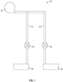
FIG. 1 is a schematic illustration of an exemplary embodiment of a fluid flow system including one or more valve assemblies; -
FIG. 2 is a cross-sectional view of an exemplary embodiment of a valve assembly; -
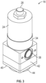
FIG. 3 is a perspective view of an exemplary embodiment of a valve assembly; -
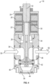
FIG. 4 is a cross-sectional view of an exemplary embodiment of a valve assembly configured as a 2 way / 2 port valve assembly; -
FIG. 5 is a cross-sectional view of an exemplary embodiment of a valve assembly configured as a 90-degree valve assembly; and -
FIG. 6 is a cross-sectional view of an exemplary embodiment of a valve assembly configured as a 3 way / 2 port valve assembly. - A detailed description of one or more embodiments of the disclosed apparatus and method are presented herein by way of exemplification and not limitation with reference to the Figures.
- Referring to
FIG. 1 , illustrated is an exemplary embodiment of afluid flow system 10, which may include afluid pump 12, a plurality offluid lines 14 extending downstream of thefluid pump 12, and one ormore valve assemblies 16 operably connected to thefluid lines 14 which are activated to control a flow of fluid to, for example, one ormore actuators 18. One skilled in the art will readily appreciate that thefluid flow system 10 is merely exemplary, and that other configurations of fluid flow systems are contemplated within the scope of the present disclosure. In some embodiments, the fluid is an oil or hydraulic fluid, while in other embodiments other fluids such as water or fuel may be utilized. - A cross-sectional view of an exemplary embodiment of a
valve assembly 16 is illustrated inFIG. 2 and a perspective view is illustrated inFIG. 3 . Thevalve assembly 16 is a solenoid valve including afirst solenoid 20 and asecond solenoid 22 disposed in asolenoid housing 24. Thesolenoids valve piston 26 and astatic core 28, with anair gap 30 defined between the valve piston and thestatic core 28. Selectively energizing of thesolenoids solenoid housing 24 which causes thevalve piston 26 to move along apiston axis 32. While the embodiment ofFIG. 2 is a solenoid valve, one skilled in the art will readily appreciate that the present disclosure may be readily applied to valves utilizing an armature as a valve actuation device. Thevalve piston 26 extends into amain body 34 of thevalve assembly 16, with the position of thevalve piston 26 along thevalve axis 32 in themain body 34 controlling a flow of fluid into and out of thevalve assembly 16. - The
valve assembly 16 includes multiple valve openings for fluid flow into and out of thevalve assembly 16. For example, in the embodiment ofFIG. 2 , themain body 34 includes a first valve opening 36 and a second valve opening 38 which, in some embodiments are located 180 degrees apart relative to thevalve axis 32. Further, thevalve assembly 16 includes a floatingbody 40 axially spaced apart from themain body 34 with ahub 42 disposed axially between themain body 34 and the floatingbody 40. A third valve opening 44 is disposed in the floatingbody 40 and is selectably fluidly connected to thefirst valve opening 36 and/or thesecond valve opening 38. Each of thevalve openings fastener openings 46 at whichfittings 48 may be secured for attachment to thevalve assembly 16. The connection type of thefittings 48 may vary, and may include a flanged end, a threaded end or a surface butt type of connection. This versatility is advantageous in that it allows for multiple types offittings 48 to be connected to thevalve assembly 16. - Referring now to
FIG. 4 , thevalve assembly 16 is configured as a 2 way/ 2port valve assembly 16, where thefirst valve opening 36 is avalve inlet 50 and the second valve opening 38 is avalve outlet 52. This is accomplished by installing aplug 54 or cover at the third valve opening 44 making the third valve opening 44 inoperable. As illustrated inFIG. 5 , thevalve assembly 16 may also be reconfigured as a 90-degree valve assembly 16 by moving theplug 54 from the third valve opening 44 to thesecond valve opening 38. Thus the third valve opening 44 is thevalve outlet 52. Similarly, the configuration could be reversed to the third valve opening 44 is thevalve inlet 50 and thefirst valve opening 36 is thevalve outlet 52. - Referring now to
FIG. 6 , when theplug 54 is completely removed from thevalve assembly 16, thevalve assembly 16 is configured as a 3 way/ 2port valve assembly 16. In this configuration, thefirst valve opening 36 may be thevalve inlet 50 and the second valve opening 38 may be thevalve outlet 38, while the third valve opening 44 may be configured as adrain 56 through which excess fluid flow is removed from thevalve assembly 16. Additionally, in some embodiments, thehub 42 is interchangeable. Replacing thehub 42 with one having a longer or shorter axial length relative to thevalve axis 32 correspondingly lengthens or shortens a stroke length of thevalve piston 26. - The
valve assemblies 16 disclosed herein allow for many different valve configurations, such as inlet and outlet positions, and stroke length from the same basic valve configuration by moving or changing select components, such as the position of theplug 54 and the configuration of thehub 42. This reduces the number ofdifferent valve assemblies 16 that must be kept in stock at, for example, a service or repair facility, which reduces overall costs associated with thevalve assemblies 16. Further, since the basic structure of thevalve assembly 16 is the same, verification and qualification efforts are reduced for each of the valve configurations. - The term "about" is intended to include the degree of error associated with measurement of the particular quantity based upon the equipment available at the time of filing the application.
- The terminology used herein is for the purpose of describing particular embodiments only and is not intended to be limiting of the present disclosure. As used herein, the singular forms "a", "an" and "the" are intended to include the plural forms as well, unless the context clearly indicates otherwise. It will be further understood that the terms "comprises" and/or "comprising," when used in this specification, specify the presence of stated features, integers, steps, operations, elements, and/or components, but do not preclude the presence or addition of one or more other features, integers, steps, operations, element components, and/or groups thereof.
- While the present disclosure has been described with reference to an exemplary embodiment or embodiments, it will be understood by those skilled in the art that various changes may be made and equivalents may be substituted for elements thereof without departing from the scope of the present disclosure. In addition, many modifications may be made to adapt a particular situation or material to the teachings of the present disclosure without departing from the essential scope thereof. Therefore, it is intended that the present disclosure not be limited to the particular embodiment disclosed as the best mode contemplated for carrying out this present disclosure, but that the present disclosure will include all embodiments falling within the scope of the claims.
Claims (15)
- A valve assembly, comprising:a valve body including a plurality of valve openings (36, 38, 44);a valve piston (26) disposed in the valve body and movable therein along a valve axis (32), the valve piston (26) configured to selectably control a flow of fluid through the valve body via the plurality of valve openings (36, 38, 44); andone or more plugs selectably installable to one or more valve openings (36, 38, 44) of the plurality of valve openings (36, 38, 44) to selectably change the valve configuration between a two-way valve and a three-way valve.
- The valve assembly of claim 1, further comprising a valve actuator operable connected to the valve piston (26) to drive movement of the valve piston (26) along the valve axis (32), and optionally wherein the valve actuator is one of pneumatically, hydraulically or electrically operated. includes one or more solenoids (20, 22).
- The valve assembly of any preceding claim, wherein the valve body includes:a valve main body; anda floating body (40) axially spaced apart from the valve main body, each of the valve main body and the valve floating body (40) including at least one valve opening of the plurality of valve openings (36, 38, 44).
- The valve assembly of claim 3, further comprising a hub disposed axially between the valve main body and the floating body (40).
- The valve assembly of claim 4, wherein an axial length of the hub determines a stroke length of the valve piston (26), and/or wherein the hub is selectably replaceable to change a stroke length of the valve piston (26).
- The valve assembly of any preceding claim, wherein each valve opening of the plurality of valve openings (36, 38, 44) have an identical configuration.
- The valve assembly of any preceding claim, further comprising one or more fastener openings at each valve opening of the plurality of valve openings (36, 38, 44) configured for connection of one or more fittings thereto.
- The valve assembly of any preceding claim, wherein the valve assembly is further configurable as a 90-degree valve.
- A fluid flow system, comprising:one or more fluid flow pathways; anda valve assembly operably connected to the one or more fluid flow pathways, the valve assembly including:a valve body including a plurality of valve openings (36, 38, 44);a valve piston (26) disposed in the valve body and movable therein along a valve axis (32), the valve piston (26) configured to selectably control a flow of fluid through the valve body via the plurality of valve openings (36, 38, 44); andone or more plugs selectably installable to one or more valve openings (36, 38, 44) of the plurality of valve openings (36, 38, 44) to change the valve configuration between a two-way valve and a three-way valve.
- The fluid flow system of claim 9, further comprising a valve actuator operable connected to the valve piston (26) to drive movement of the valve piston (26) along the valve axis (32), and optionally wherein the valve actuator is one or more off hydraulically, pneumatically or electrically operated.
- The fluid flow system of any of claims 9 to 10, wherein the valve body includes:a valve main body; anda floating body (40) axially spaced apart from the valve main body, each of the valve main body and the valve floating body (40) including at least one valve opening of the plurality of valve openings (36, 38, 44).
- The fluid flow system of claim 11, further comprising a hub disposed axially between the valve main body and the floating body (40), and optionally wherein an axial length of the hub determines a stroke length of the valve piston (26).
- The fluid flow system of any of claims 9 to 12, wherein each valve opening of the plurality of valve openings (36, 38, 44) have an identical configuration.
- A method of assembling a valve assembly comprising:installing a valve piston (26) into a valve body, the valve body including a plurality of valve openings (36, 38, 44) therein;installing a plug in a first valve opening of the plurality of valve openings (36, 38, 44) to block the flow of fluid through the valve opening and define a first valve configuration; andremoving the plug from the first valve opening to change the configuration of the valve assembly to a second valve configuration.
- The method of claim 14, further comprising installing the plug in a second valve opening of the plurality of valve openings (36, 38, 44) to change the configuration of the valve assembly to a third configuration, and/or wherein the valve body includes a hub installed therein, the hub defining a stroke length of the valve piston (26); and
further comprising exchanging a first hub having a first axial length for a second hub having a second hub length, thereby changing the stroke length from a first stroke length to a second stroke length which in turn impact the flow rate of the valve.
Applications Claiming Priority (1)
| Application Number | Priority Date | Filing Date | Title |
|---|---|---|---|
| IN202311088097 | 2023-12-22 |
Publications (1)
| Publication Number | Publication Date |
|---|---|
| EP4575280A1 true EP4575280A1 (en) | 2025-06-25 |
Family
ID=93925893
Family Applications (1)
| Application Number | Title | Priority Date | Filing Date |
|---|---|---|---|
| EP24222515.9A Pending EP4575280A1 (en) | 2023-12-22 | 2024-12-20 | Modular valve assembly |
Country Status (2)
| Country | Link |
|---|---|
| US (1) | US20250207680A1 (en) |
| EP (1) | EP4575280A1 (en) |
Citations (2)
| Publication number | Priority date | Publication date | Assignee | Title |
|---|---|---|---|---|
| EP0224936A2 (en) * | 1985-12-06 | 1987-06-10 | Karl-Thomas Dipl.-Ing. Rhody | Proportional directional valve with single pressure balance |
| EP1386084B1 (en) * | 2001-05-05 | 2006-01-11 | Bosch Rexroth AG | Hydraulic control assembly for controlling the direction and speed of a single-action hydraulic consumer and a directional control valve therefor |
-
2024
- 2024-03-13 US US18/603,799 patent/US20250207680A1/en not_active Abandoned
- 2024-12-20 EP EP24222515.9A patent/EP4575280A1/en active Pending
Patent Citations (2)
| Publication number | Priority date | Publication date | Assignee | Title |
|---|---|---|---|---|
| EP0224936A2 (en) * | 1985-12-06 | 1987-06-10 | Karl-Thomas Dipl.-Ing. Rhody | Proportional directional valve with single pressure balance |
| EP1386084B1 (en) * | 2001-05-05 | 2006-01-11 | Bosch Rexroth AG | Hydraulic control assembly for controlling the direction and speed of a single-action hydraulic consumer and a directional control valve therefor |
Also Published As
| Publication number | Publication date |
|---|---|
| US20250207680A1 (en) | 2025-06-26 |
Similar Documents
| Publication | Publication Date | Title |
|---|---|---|
| EP2638297B1 (en) | Hydraulic or pneumatic drive for actuating a fitting comprising a control valve or selector valve | |
| EP3129660B1 (en) | Servo valve | |
| US9625053B2 (en) | Hydraulic actuator lockout | |
| US9708886B2 (en) | Control choke system | |
| US20250207680A1 (en) | Modular valve assembly | |
| EP3181967A1 (en) | Valve | |
| CA3188078C (en) | Actuator assemblies and related methods for valve systems | |
| US12215791B2 (en) | Flapper servo valve | |
| DE3222851C1 (en) | Fan drive for a cooling system, especially for rail vehicles | |
| EP3169902B1 (en) | Screw compressor | |
| EP4276335B1 (en) | Servo valve assembly | |
| BR102024027007A2 (en) | VALVE ASSEMBLY, VALVE ASSEMBLY, FLUID FLOW SYSTEM, AND METHOD OF ASSEMBLY OF VALVE ASSEMBLY | |
| US11078931B2 (en) | Servo valve | |
| DE10241977B4 (en) | Highly dynamic servo valve control device | |
| DE102009012752A1 (en) | Valve i.e. proportional pressure regulating valve, for use in connection line of hydraulic or pneumatic actuator operating system, has bypass line between fluid inlet and fluid outlet, and pressure relief valve located in bypass line | |
| WO1985003556A1 (en) | A pneumatic servo valve (governing valve) | |
| DE2312883A1 (en) | VALVE | |
| DE102015114761A1 (en) | Electro-pneumatic control unit for a control device | |
| US12486915B2 (en) | Single stage servo valve assembly | |
| JPS63190984A (en) | Cartridge valve | |
| DE4103665A1 (en) | Electromagnetically operated valve - has cylindrical magnetostrictive actuator which contracts in axial magnetic field of selectively energised windings to allow fluid flow between adjacent ports | |
| DE102012107725A1 (en) | Valve device for a hydraulic circuit and oil pump control arrangement | |
| EP0764242A1 (en) | Actuator for a control cylinder | |
| DE102016011059B4 (en) | Seat valve with electromagnetic actuation | |
| DE2617297A1 (en) | Electrohydraulically operated ball valve - has housing containing two bushings with holes in base acting as valve seats |
Legal Events
| Date | Code | Title | Description |
|---|---|---|---|
| PUAI | Public reference made under article 153(3) epc to a published international application that has entered the european phase |
Free format text: ORIGINAL CODE: 0009012 |
|
| STAA | Information on the status of an ep patent application or granted ep patent |
Free format text: STATUS: THE APPLICATION HAS BEEN PUBLISHED |
|
| AK | Designated contracting states |
Kind code of ref document: A1 Designated state(s): AL AT BE BG CH CY CZ DE DK EE ES FI FR GB GR HR HU IE IS IT LI LT LU LV MC ME MK MT NL NO PL PT RO RS SE SI SK SM TR |
|
| STAA | Information on the status of an ep patent application or granted ep patent |
Free format text: STATUS: THE APPLICATION IS DEEMED TO BE WITHDRAWN |