EP4575268A1 - Working vehicle - Google Patents
Working vehicle Download PDFInfo
- Publication number
- EP4575268A1 EP4575268A1 EP24220174.7A EP24220174A EP4575268A1 EP 4575268 A1 EP4575268 A1 EP 4575268A1 EP 24220174 A EP24220174 A EP 24220174A EP 4575268 A1 EP4575268 A1 EP 4575268A1
- Authority
- EP
- European Patent Office
- Prior art keywords
- transmission casing
- hydraulic
- transmission
- fluid
- casing
- Prior art date
- Legal status (The legal status is an assumption and is not a legal conclusion. Google has not performed a legal analysis and makes no representation as to the accuracy of the status listed.)
- Pending
Links
Images






Classifications
-
- F—MECHANICAL ENGINEERING; LIGHTING; HEATING; WEAPONS; BLASTING
- F16—ENGINEERING ELEMENTS AND UNITS; GENERAL MEASURES FOR PRODUCING AND MAINTAINING EFFECTIVE FUNCTIONING OF MACHINES OR INSTALLATIONS; THERMAL INSULATION IN GENERAL
- F16H—GEARING
- F16H57/00—General details of gearing
- F16H57/04—Features relating to lubrication or cooling or heating
- F16H57/0409—Features relating to lubrication or cooling or heating characterised by increasing efficiency, e.g. by reducing splash losses
-
- F—MECHANICAL ENGINEERING; LIGHTING; HEATING; WEAPONS; BLASTING
- F16—ENGINEERING ELEMENTS AND UNITS; GENERAL MEASURES FOR PRODUCING AND MAINTAINING EFFECTIVE FUNCTIONING OF MACHINES OR INSTALLATIONS; THERMAL INSULATION IN GENERAL
- F16H—GEARING
- F16H47/00—Combinations of mechanical gearing with fluid clutches or fluid gearing
- F16H47/02—Combinations of mechanical gearing with fluid clutches or fluid gearing the fluid gearing being of the volumetric type
-
- F—MECHANICAL ENGINEERING; LIGHTING; HEATING; WEAPONS; BLASTING
- F16—ENGINEERING ELEMENTS AND UNITS; GENERAL MEASURES FOR PRODUCING AND MAINTAINING EFFECTIVE FUNCTIONING OF MACHINES OR INSTALLATIONS; THERMAL INSULATION IN GENERAL
- F16H—GEARING
- F16H57/00—General details of gearing
- F16H57/02—Gearboxes; Mounting gearing therein
- F16H57/021—Shaft support structures, e.g. partition walls, bearing eyes, casing walls or covers with bearings
-
- F—MECHANICAL ENGINEERING; LIGHTING; HEATING; WEAPONS; BLASTING
- F16—ENGINEERING ELEMENTS AND UNITS; GENERAL MEASURES FOR PRODUCING AND MAINTAINING EFFECTIVE FUNCTIONING OF MACHINES OR INSTALLATIONS; THERMAL INSULATION IN GENERAL
- F16H—GEARING
- F16H57/00—General details of gearing
- F16H57/04—Features relating to lubrication or cooling or heating
- F16H57/0408—Exchange, draining or filling of transmission lubricant
-
- F—MECHANICAL ENGINEERING; LIGHTING; HEATING; WEAPONS; BLASTING
- F16—ENGINEERING ELEMENTS AND UNITS; GENERAL MEASURES FOR PRODUCING AND MAINTAINING EFFECTIVE FUNCTIONING OF MACHINES OR INSTALLATIONS; THERMAL INSULATION IN GENERAL
- F16H—GEARING
- F16H57/00—General details of gearing
- F16H57/04—Features relating to lubrication or cooling or heating
- F16H57/0447—Control of lubricant levels, e.g. lubricant level control dependent on temperature
-
- B—PERFORMING OPERATIONS; TRANSPORTING
- B60—VEHICLES IN GENERAL
- B60Y—INDEXING SCHEME RELATING TO ASPECTS CROSS-CUTTING VEHICLE TECHNOLOGY
- B60Y2200/00—Type of vehicle
- B60Y2200/20—Off-Road Vehicles
- B60Y2200/22—Agricultural vehicles
- B60Y2200/221—Tractors
-
- F—MECHANICAL ENGINEERING; LIGHTING; HEATING; WEAPONS; BLASTING
- F16—ENGINEERING ELEMENTS AND UNITS; GENERAL MEASURES FOR PRODUCING AND MAINTAINING EFFECTIVE FUNCTIONING OF MACHINES OR INSTALLATIONS; THERMAL INSULATION IN GENERAL
- F16H—GEARING
- F16H37/00—Combinations of mechanical gearings, not provided for in groups F16H1/00 - F16H35/00
- F16H37/02—Combinations of mechanical gearings, not provided for in groups F16H1/00 - F16H35/00 comprising essentially only toothed or friction gearings
- F16H37/06—Combinations of mechanical gearings, not provided for in groups F16H1/00 - F16H35/00 comprising essentially only toothed or friction gearings with a plurality of driving or driven shafts; with arrangements for dividing torque between two or more intermediate shafts
- F16H37/08—Combinations of mechanical gearings, not provided for in groups F16H1/00 - F16H35/00 comprising essentially only toothed or friction gearings with a plurality of driving or driven shafts; with arrangements for dividing torque between two or more intermediate shafts with differential gearing
- F16H37/0833—Combinations of mechanical gearings, not provided for in groups F16H1/00 - F16H35/00 comprising essentially only toothed or friction gearings with a plurality of driving or driven shafts; with arrangements for dividing torque between two or more intermediate shafts with differential gearing with arrangements for dividing torque between two or more intermediate shafts, i.e. with two or more internal power paths
- F16H37/084—Combinations of mechanical gearings, not provided for in groups F16H1/00 - F16H35/00 comprising essentially only toothed or friction gearings with a plurality of driving or driven shafts; with arrangements for dividing torque between two or more intermediate shafts with differential gearing with arrangements for dividing torque between two or more intermediate shafts, i.e. with two or more internal power paths at least one power path being a continuously variable transmission, i.e. CVT
- F16H2037/088—Power-split transmissions with summing differentials, with the input of the CVT connected or connectable to the input shaft
- F16H2037/0886—Power-split transmissions with summing differentials, with the input of the CVT connected or connectable to the input shaft with switching means, e.g. to change ranges
-
- F—MECHANICAL ENGINEERING; LIGHTING; HEATING; WEAPONS; BLASTING
- F16—ENGINEERING ELEMENTS AND UNITS; GENERAL MEASURES FOR PRODUCING AND MAINTAINING EFFECTIVE FUNCTIONING OF MACHINES OR INSTALLATIONS; THERMAL INSULATION IN GENERAL
- F16H—GEARING
- F16H57/00—General details of gearing
- F16H57/02—Gearboxes; Mounting gearing therein
- F16H2057/02039—Gearboxes for particular applications
- F16H2057/02043—Gearboxes for particular applications for vehicle transmissions
- F16H2057/02056—Gearboxes for particular applications for vehicle transmissions for utility vehicles, e.g. tractors or agricultural machines
-
- F—MECHANICAL ENGINEERING; LIGHTING; HEATING; WEAPONS; BLASTING
- F16—ENGINEERING ELEMENTS AND UNITS; GENERAL MEASURES FOR PRODUCING AND MAINTAINING EFFECTIVE FUNCTIONING OF MACHINES OR INSTALLATIONS; THERMAL INSULATION IN GENERAL
- F16H—GEARING
- F16H47/00—Combinations of mechanical gearing with fluid clutches or fluid gearing
- F16H47/02—Combinations of mechanical gearing with fluid clutches or fluid gearing the fluid gearing being of the volumetric type
- F16H47/04—Combinations of mechanical gearing with fluid clutches or fluid gearing the fluid gearing being of the volumetric type the mechanical gearing being of the type with members having orbital motion
-
- F—MECHANICAL ENGINEERING; LIGHTING; HEATING; WEAPONS; BLASTING
- F16—ENGINEERING ELEMENTS AND UNITS; GENERAL MEASURES FOR PRODUCING AND MAINTAINING EFFECTIVE FUNCTIONING OF MACHINES OR INSTALLATIONS; THERMAL INSULATION IN GENERAL
- F16H—GEARING
- F16H61/00—Control functions within control units of change-speed- or reversing-gearings for conveying rotary motion ; Control of exclusively fluid gearing, friction gearing, gearings with endless flexible members or other particular types of gearing
- F16H61/38—Control of exclusively fluid gearing
- F16H61/40—Control of exclusively fluid gearing hydrostatic
- F16H61/4078—Fluid exchange between hydrostatic circuits and external sources or consumers
- F16H61/4139—Replenishing or scavenging pumps, e.g. auxiliary charge pumps
Definitions
- the present invention relates to working vehicles.
- the working vehicle disclosed in Japanese Unexamined Patent Application Publication No. 2012-40944 includes a continuously-variable-transmission casing and a primary transmission casing.
- the continuously-variable-transmission casing includes a hydraulic transmission chamber that accommodates a hydraulic pump and a hydraulic motor driven by fluid delivered from the hydraulic pump.
- the primary transmission casing is adjacent to the hydraulic transmission chamber and accommodates a primary transmission (distributive transmission 15A) including an input gear that receives power from a prime mover, and also including a transmission gear that transmits the power transmitted from the input gear to the hydraulic pump.
- the hydraulic transmission chamber is completely filled with the fluid, and the primary transmission casing is in a state where the fluid flows to and from the hydraulic transmission chamber.
- the interior of the primary transmission casing is also completely filled with the fluid.
- an object of the present invention is to provide working vehicles each that can reduce the gear stirring resistance within the primary transmission casing provided adjacent to the hydraulic transmission chamber that accommodates the hydraulic pump and the hydraulic motor.
- a working vehicle includes a hydraulic transmission chamber to accommodate a hydraulic pump and a hydraulic motor driven by fluid delivered from the hydraulic pump, and a primary transmission casing to accommodate a primary transmission including an input gear to receive power from a prime mover and a transmission gear to transmit power from the input gear to the hydraulic pump.
- the primary transmission casing is adjacent to the hydraulic transmission chamber. An interior of the primary transmission casing is separated from the hydraulic transmission chamber.
- the working vehicle may include an orifice to allow the hydraulic transmission chamber and the interior of the primary transmission casing to communicate with each other.
- the hydraulic transmission chamber and the interior of the primary transmission casing may be separated from each other such that fluid in the hydraulic transmission chamber does not flow into the primary transmission casing through or in any portion except for the orifice.
- the working vehicle may include a supply pump operable to replenish the hydraulic transmission chamber with purged fluid, and an outflow passage to cause fluid inside the primary transmission casing to flow out.
- a fluid flow amount of the orifice may be determined such that the hydraulic transmission chamber is completely filled with fluid and a fluid level of the fluid inside the primary transmission casing is located at a vertically intermediate portion inside the primary transmission casing.
- the working vehicle may include a continuously-variable-transmission casing including the hydraulic transmission chamber, and a travel-drive transmission casing to accommodate a travel-drive transmission that is configured to speed-change power output from the hydraulic motor and transmit the speed-changed power to a drive wheel.
- the travel-drive transmission casing may be coupled to a portion of the continuously-variable-transmission casing opposite from the primary transmission casing.
- the supply pump may be configured to replenish the hydraulic transmission chamber with fluid sucked from the inside of the travel-drive transmission casing via an oil filter.
- the outflow passage may be configured to cause fluid inside the primary transmission casing to flow out into the travel-drive transmission casing.
- the input gear may be located at an upper portion inside the primary transmission casing and higher than the first transmission gear.
- the orifice may be located at a height within a range of a tip diameter of the input gear.
- the working vehicle may include a plug to block a through-hole extending through a wall and to separate the hydraulic transmission chamber and the interior of the primary transmission casing from each other.
- the orifice may be provided in the plug.
- the orifice may include an increasing-diameter hole that connects the narrow hole and the wide hole to each other.
- the increasing-diameter hole may gradually increase in diameter from the narrow hole toward the wide hole.
- the interior of the transmission casing adjacent to the hydraulic transmission chamber is a separate chamber from the hydraulic transmission chamber, so that the height of the fluid level inside the transmission casing can be reduced. Accordingly, the gear stirring resistance inside the transmission casing can be reduced. Consequently, horsepower loss can be reduced.
- FIG. 1 illustrates a side view of a working vehicle 1 according to this embodiment.
- a tractor is illustrated as an example of the working vehicle 1.
- the working vehicle 1 is described as being a tractor below, the working vehicle 1 is not limited to a tractor.
- the tractor 1 includes an operator's seat 2 where an operator sits.
- a direction extending forward (direction of an arrow A1 in FIG. 1 ) from the operator sitting in the operator's seat 2 will be described as a forward direction
- a direction extending rearward (direction of an arrow A2 in FIG. 1 ) from the operator will be described as a rearward direction
- a direction extending leftward (toward the viewer of FIG. 1 ) from the operator will be described as a leftward direction
- a direction extending rightward (away from the viewer of FIG. 1 ) will be described as a rightward direction.
- a direction indicated by an arrow K1 in FIG. 1 will be described as a front-rear direction.
- a horizontal direction orthogonal to the front-rear direction K1 will be described as a vehicle-body width direction.
- a direction extending from the middle toward the right or the left of the tractor 1 will be described as a vehicle-body-width outward direction.
- a direction extending from the right or the left of the tractor 1 toward the middle of the tractor 1 will be described as a vehicle-body-width inward direction.
- the tractor 1 includes a vehicle body 3, front wheels 4 located at the left and right of a front portion of the vehicle body 3, rear wheels 5 located at the left and right of a rear portion of the vehicle body 3, and an operation portion 7 located higher than the vehicle body 3 and including a steering wheel 6, the operator's seat 2, and the like.
- the front wheels 4 are steered wheels that are steerable.
- the front wheels 4 and the rear wheels 5 are drive wheels that are drivable.
- the drive wheels may be the rear wheels 5 alone, or may be the front wheels 4 alone.
- the front wheels 4 and the rear wheels 5 define a traveling device that supports the vehicle body 3 in a travelable manner.
- the vehicle body 3 includes an engine (prime mover) 8 as a power source, a front frame coupled to the engine 8 and protruding forward from the engine 8, and a power transmitting case 10 coupled to a rear portion of the engine 8 and extending rearward from the engine 8.
- a power take-off (PTO) shaft 9 that extracts power of the engine 8 to the outside is located at a rear portion of the power transmitting case 10 (vehicle body 3).
- the engine 8 is a diesel engine.
- the engine 8 may be a gasoline engine.
- the power source may be a prime mover other than an engine.
- the power source may be an electric motor.
- the power transmitting case 10 includes a flywheel housing 11 coupled to the rear portion of the engine 8, a clutch housing 12 coupled to a rear portion of the flywheel housing 11, a continuously-variable-transmission casing 13 coupled to a rear portion of the clutch housing 12, and a travel-drive transmission casing 14 coupled to a rear portion of the continuously-variable-transmission casing 13.
- the flywheel housing 11 accommodates a flywheel 15 that rotates integrally with a crankshaft of the engine 8.
- the clutch housing 12 accommodates a main clutch 16 that intermittently transmits the power of the engine 8 transmitted via the flywheel 15.
- the continuously-variable-transmission casing 13 accommodates a hydraulic pump (called an HST pump) 18 and a hydraulic motor (called an HST motor) 19 included in a continuously variable transmission (hydro-static continuously variable transmission (HST)) 17 (see FIGS. 8 and 9 ).
- the travel-drive transmission casing 14 accommodates a travel-drive transmission (see FIG. 3 ) 20 that speed-changes power output from the continuously variable transmission 17 and transmits the power to the drive wheels.
- FIG. 3 illustrates a primary power transmitting system 21 that transmits the power of the engine 8.
- the primary power transmitting system 21 includes a primary transmission 22 that distributively transmits the power of the engine 8, a travel-power transmitting system 23 that transmits the power of the engine 8 to the drive wheels (the front wheels 4 and/or the rear wheels 5), and a PTO-power transmitting system 24 that transmits the power of the engine 8 to the PTO shaft 9.
- the primary transmission 22 includes an input gear 25 and a pair of transmission gears 26 and 27.
- the input gear 25 is integrated with a shaft 28 extending forward from the input gear 25.
- the power of the engine 8 after the flywheel 15 and the main clutch 16 is transmitted to the input gear 25 via the shaft 28.
- the input gear 25 includes a supported portion 25a protruding rearward from the rotation center.
- the input gear 25 meshes with the pair of transmission gears 26 and 27 and transmits the power to the pair of transmission gears 26 and 27.
- the first transmission gear 26 as one of the gears in the pair of transmission gears 26 and 27 rotates integrally with a first transmitting shaft 29.
- the second transmission gear 27 as the other one of the gears in the pair of transmission gears 26 and 27 rotates integrally with a second transmitting shaft 30.
- the first transmission gear 26 includes a first supported portion 26a protruding forward and a second supported portion 26b protruding rearward.
- the second transmission gear 27 includes a first supported portion 27a protruding forward and a second supported portion 27b protruding rearward.
- the travel-power transmitting system 23 includes a continuously variable transmission 17 to which the power from the engine 8 is transmitted, and the travel-drive transmission 20 that speed-changes the power output from the continuously variable transmission 17 and transmits the power to the drive wheels.
- the continuously variable transmission 17 includes the HST pump 18 and the HST motor 19.
- the HST pump 18 is driven by the power from the engine 8.
- the HST motor 19 is rotationally driven by fluid delivered from the HST pump 18.
- the HST pump 18 includes a swash-plate variable displacement pump.
- the power from the engine 8 is transmitted to the HST pump 18 via the first transmitting shaft 29, and the HST pump 18 is driven by rotational power of the first transmitting shaft 29.
- the angle of the swash plate is changed by a cylinder 31 by operating the cylinder 31 operating in conjunction with the swash plate, whereby the delivery amount and the delivery direction are changeable.
- the HST motor 19 is closed-circuit-connected to the HST pump 18 by a pair of transmission fluid passages 32a and 32b.
- the HST motor 19 is rotationally driven in the forward rotational direction or the reverse rotational direction by the fluid delivered from the HST pump 18, and outputs, from a motor shaft 33, rotational power steplessly speed-changed and rotated in either of the forward rotational direction and the reverse rotational direction.
- the continuously variable transmission 17 can be set to a neutral state located between the forward rotational state and the reverse rotational state by changing the angle of the swash plate of the HST pump 18.
- the lower-pressure transmission fluid passage 32a or 32b can be replenished with fluid via a charge circuit 34.
- the charge circuit 34 includes high-pressure relief valves 35a and 35b that release pressure to the lower-pressure transmission fluid passage 32a or 32b when the pressure in the higher-pressure transmission fluid passage 32a or 32b becomes higher than or equal to a set value, a fluid passage 36 between the high-pressure relief valve 35a and the high-pressure relief valve 35b, and a replenishment fluid passage 39 connected to the fluid passage 36.
- the fluid passage 36 is supplied with delivery fluid from a supply pump (charge pump) 87.
- the supply pump 87 is driven by the first transmitting shaft 29 to suction fluid (transmission fluid) in the travel-drive transmission casing 14 via an oil filter 37 and delivers the fluid.
- the fluid delivered from the supply pump 87 flows to the fluid passage 36 via an oil filter 38 and the replenishment fluid passage 39.
- the charge circuit 34 includes a charge relief valve 40 that sets the circuit pressure in the charge circuit 34, and the charge relief valve 40 communicates with the replenishment fluid passage 39.
- the continuously-variable-transmission casing 13 includes a hydraulic transmission chamber 41 that accommodates the HST pump 18 and the HST motor 19.
- the hydraulic transmission chamber 41 includes a front wall 42 serving as a front portion of the hydraulic transmission chamber 41, a top wall 43 serving as a top portion, a bottom wall 44 serving as a bottom portion, left and right sidewalls 45a and 45b serving as left and right portions, and a port plate 46 serving as a rear portion.
- the interior of the hydraulic transmission chamber 41 is completely filled with fluid.
- the fluid (purged fluid) from the supply pump 87 is suppliable into the hydraulic transmission chamber 41.
- the fluid can be replenished into the hydraulic transmission chamber 41 from the replenishment fluid passage 39.
- the travel-drive transmission 20 includes a planetary gear mechanism 47, a forward-rearward-travel switching mechanism 48, and a secondary transmission mechanism 49.
- the planetary gear mechanism 47 includes a sun gear 47a, a plurality of planetary gears 47b provided around the sun gear 47a, a carrier 47c that rotatably supports each planetary gear 47b, a ring gear 47d that meshes with the plurality of planetary gears 47b, and an output shaft 47e that outputs power.
- Rotational power output from the motor shaft 33 of the HST motor 19 is input to the sun gear 47a.
- Rotational power of the second transmitting shaft 30 is input to the carrier 47c.
- the planetary gear mechanism 47 combines a driving force from the continuously variable transmission 17 with a driving force from the engine 8 not affected by a speed-changing operation of the continuously variable transmission 17, and outputs the combined driving force from the output shaft 47e to an input shaft 48a of the forward-rearward-travel switching mechanism 48.
- the forward-rearward-travel switching mechanism 48 outputs the driving force transmitted to the input shaft 48a from either of a forward-travel output gear train 48b that transmits forward-travel power and a rearward-travel gear train 48c that transmits rearward-travel power.
- the forward-rearward-travel switching mechanism 48 includes a switch clutch 48d that switches the power transmitting mode between a forward-travel transmitting mode and a rearward-travel transmitting mode.
- the secondary transmission mechanism 49 switches power output from an output shaft 48e of the forward-rearward-travel switching mechanism 48 to any of a lower speed mode, an intermediate speed mode, and a high speed mode, and outputs the power.
- the power output from the secondary transmission mechanism 49 is transmitted to the rear wheels 5 via a rear-wheel differential mechanism 50.
- the power output from the secondary transmission mechanism 49 is transmitted to the front wheels 4 via a front-wheel-power extracting gear train 51, a clutch mechanism 52, a front-wheel-power transmitting shaft 53, a front-wheel differential mechanism 54, and the like.
- a primary transmission casing 55 that accommodates the primary transmission 22 is attached to the front surface of the front wall 42 of the continuously-variable-transmission casing 13.
- the travel-drive transmission casing 14 is coupled to a portion of the continuously-variable-transmission casing 13 opposite from the primary transmission casing 55.
- an annular attachment bracket 56 is provided to protrude forward from the front surface of the front wall 42 of the continuously-variable-transmission casing 13.
- the primary transmission casing 55 includes a case front-wall 55a and an outer peripheral wall 55b extending rearward from the outer periphery of the case front-wall 55a.
- the primary transmission casing 55 is attached to the front wall 42 of the continuously-variable-transmission casing 13 by setting the rear surface of the outer peripheral wall 55b over the front surface of the attachment bracket 56 of the continuously-variable-transmission casing 13 and fixing the outer peripheral wall 55b to the attachment bracket 56 with bolts.
- the front wall 42 defines the front portion of the hydraulic transmission chamber 41. Therefore, the primary transmission casing 55 is provided adjacent to the hydraulic transmission chamber 41.
- the input gear 25 is located higher than substantially the middle, in the vehicle-body width direction, of the interior of the primary transmission casing 55.
- the first transmission gear 26 is located diagonally rightward of and lower than the input gear 25.
- the second transmission gear 27 is located diagonally leftward of and lower than the input gear 25.
- the second transmission gear 27 is located such that the upper end thereof is located higher than the upper end of the first transmission gear 26.
- the gears included in the primary transmission 22 are located astride the interior of the primary transmission casing 55 and the inside of the attachment bracket 56. Therefore, the interior of the primary transmission casing 55 and the space inside the attachment bracket 56 (the primary transmission casing 55 and a partition wall 57 to be described later) define a hydraulic transmission chamber that accommodates the primary transmission 22.
- the open hole 67 includes a fitting hole 70 at a front portion and a stepped hole 71 at a rear portion.
- a shaft bearing 72 that rotatably supports the input gear 25 (supported portion 25a) is fitted in the fitting hole 70.
- the stepped hole 71 has a front portion with a large diameter, and has a rear portion with a small diameter that is smaller than that of the front portion.
- the blocking member 66 is fitted in the stepped hole 71.
- the blocking member 66 includes a circular-disk-shaped disk 66a fitted in a small-diameter portion 71a of the stepped hole 71 and an annular flange 66b fitted in a large-diameter portion 71b of the stepped hole 71.
- An O-ring 73 that prevents fluid in the hydraulic transmission chamber 41 from traveling through between the disk 66a and the small-diameter portion 71a of the stepped hole 71 and flowing into the primary transmission casing 55 is fitted to the outer peripheral surface of the disk 66a.
- the aforementioned hydraulic transmission chamber 41 is completely filled with fluid and is supplied with fluid from the supply pump 87, so that the fluid in the hydraulic transmission chamber 41 is in a pressurized state. Because the fluid passing through the orifice 76 flows into the primary transmission casing 55 from the narrow hole 76a via the increasing-diameter hole 76c and the wide hole 76b, the flow speed of the fluid flowing out from the orifice 76 can be alleviated.
- the hydraulic transmission chamber 41 and the interior of the primary transmission casing 55 are separated from each other by the partition wall 57, the open hole 67 provided in the main wall 65 of the partition wall 57 is blocked by the blocking member 66, the outer peripheral surface of the disk 66a of the blocking member 66 is provided with the O-ring 73, and the O-ring 73, the fluid seal 79, and the fluid seal 82 prevent fluid from flowing from the hydraulic transmission chamber 41 toward the primary transmission casing 55, so that the interior of the primary transmission casing 55 can be a separate chamber from the hydraulic transmission chamber 41. Furthermore, the hydraulic transmission chamber 41 and the interior of the primary transmission casing 55 can be separated from each other to prevent the fluid in the hydraulic transmission chamber 41 from flowing into the primary transmission casing 55 through or in any portion except for the orifice 76.
- the gear stirring resistance inside the primary transmission casing 55 is large.
- horsepower loss occurs due to the large gear stirring resistance.
- the interior of the primary transmission casing 55 is a separate chamber from the hydraulic transmission chamber 41, so that the height of a fluid level 84 of the fluid inside the primary transmission casing 55 can be reduced to be located at a vertically intermediate portion (intermediate portion in the up-down direction), as illustrated in FIG. 10 . Accordingly, the gear stirring resistance inside the primary transmission casing 55 can be reduced. Consequently, horsepower loss can be reduced.
- an upper-end opening of the first fluid passage 85a is located at substantially the same height as the height position of the bottom of the primary transmission casing 55.
- the outflow passage 85 is configured to cause the fluid inside the primary transmission casing 55 to flow out from the bottom.
- the second fluid passage 85b allows the first fluid passage 85a and a cavity 86 provided in the continuously-variable-transmission casing 13 to communicate with each other.
- the cavity 86 is provided lower than the bottom wall 44 serving as the bottom of the hydraulic transmission chamber 41 in the continuously-variable-transmission casing 13.
- the cavity 86 is open rearward and communicates with the interior of the travel-drive transmission casing 14.
- the fluid inside the primary transmission casing 55 flows through the outflow passage 85 and the cavity 86 from the bottom of the primary transmission casing 55 and flows into the travel-drive transmission casing 14. Because the interior of the primary transmission casing 55 communicates with the interior of the travel-drive transmission casing 14, the height of the fluid level 84 of the fluid inside the primary transmission casing 55 is substantially the same as the height of the fluid level of the fluid inside the travel-drive transmission casing 14.
- the outflow passage 85 and the cavity 86 define a communication passage that allows the interior of the primary transmission casing 55 and the interior of the travel-drive transmission casing 14 to communicate with each other, whereby the height of the fluid level 84 of the fluid inside the primary transmission casing 55 can be set to the height of the vertically intermediate portion of the primary transmission casing 55.
- the fluid flow amount (hole diameter) of the orifice 76 is set such that the hydraulic transmission chamber 41 is completely filled with fluid and that the fluid level 84 of the fluid inside the primary transmission casing 55 is located at the vertically intermediate portion inside the primary transmission casing 55.
- the hydraulic transmission chamber 41 is supplied with purged fluid delivered from the supply pump 87, the cleanliness of the fluid inside the hydraulic transmission chamber 41 can be enhanced. Furthermore, because the hydraulic transmission chamber 41 is supplied with fluid delivered from the supply pump 87 and traveled through the oil filter 38, the cleanliness of the fluid inside the hydraulic transmission chamber 41 can be further enhanced.
- the fluid inside the primary transmission casing 55 flows toward the travel-drive transmission casing 14 from the bottom of the primary transmission casing 55, and the fluid in the hydraulic transmission chamber 41 flows into the primary transmission casing 55 from the orifice 76, thereby achieving purging of the fluid in the primary transmission casing 55.
- the structure for providing the aforementioned orifice 76 is not limited to the structure according to this embodiment.
- the orifice 76 may be provided not in the plug 75 but directly in the partition wall that separates the hydraulic transmission chamber 41 and the interior of the primary transmission casing 55 from each other.
- the orifice 76 is provided at the height position of the rotation center of the input gear 25 in the above embodiment, the position where the orifice 76 is provided is not limited.
- the orifice 76 may be provided higher than the height of the fluid level 84 of the fluid inside the primary transmission casing 55.
- the orifice 76 may be provided at a height position within the range of a tip diameter D 1 (see FIG. 10 ) of the input gear 25.
- the open hole 67 does not have to be provided with the stepped hole 71 so long as the open hole 67 includes the fitting hole 70. In other words, the rear portion of the open hole 67 may be blocked. In this case, the blocking member 66 is not provided.
- Example embodiments of the present invention provide working vehicles 1 according to the following items.
- a working vehicle 1 comprising a hydraulic transmission chamber 41 to accommodate a hydraulic pump 18 and a hydraulic motor 19 driven by fluid delivered from the hydraulic pump 18, and a primary transmission casing 55 to accommodate a primary transmission 22 including an input gear 25 to receive power from a prime mover 8 and a transmission gear 26 to transmit power from the input gear 25 to the hydraulic pump 18, the primary transmission casing 55 being adjacent to the hydraulic transmission chamber 41, wherein an interior of the primary transmission casing 55 is separated from the hydraulic transmission chamber 41.
- the interior of the primary transmission casing 55 adjacent to the hydraulic transmission chamber 41 is a separate chamber from the hydraulic transmission chamber 41, so that the height of the fluid level 84 inside the primary transmission casing 55 can be reduced. Accordingly, the gear stirring resistance inside the primary transmission casing 55 can be reduced. Consequently, horsepower loss can be reduced.
- (Item 2) The working vehicle 1 according to item 1, further comprising an orifice 76 to allow the hydraulic transmission chamber 41 and the interior of the primary transmission casing 55 to communicate with each other, wherein the hydraulic transmission chamber 41 and the interior of the primary transmission casing 55 are separated from each other such that fluid in the hydraulic transmission chamber 41 does not flow into the primary transmission casing 55 through or in any portion except for the orifice 76.
- the height of the fluid level 84 inside the primary transmission casing 55 can be reduced, so that the gear stirring resistance inside the primary transmission casing 55 can be reduced.
- the cleanliness of the fluid in the hydraulic transmission chamber 41 and the primary transmission casing 55 can be enhanced. Furthermore, with the hydraulic transmission chamber 41 and the primary transmission casing 55 communicating with each other through the orifice 76, the height of the fluid level in the primary transmission casing 55 can be maintained at the height position of the vertically intermediate portion (i.e., intermediate portion in the up-down direction).
- the working vehicle 1 according to item 3, further comprising a continuously-variable-transmission casing 13 including the hydraulic transmission chamber 41, and a travel-drive transmission casing 14 to accommodate a travel-drive transmission 20 that is configured to speed-change power output from the hydraulic motor 19 and transmit the speed-changed power to a drive wheel 4, 5, the travel-drive transmission casing being coupled to a portion of the continuously-variable-transmission casing 13 opposite from the primary transmission casing 55, wherein the supply pump 87 is configured to replenish the hydraulic transmission chamber 41 with fluid sucked from the inside of the travel-drive transmission casing 14 via an oil filter 37, and the outflow passage 85 is configured to cause fluid inside the primary transmission casing 55 to flow out into the travel-drive transmission casing 14.
- the fluid in the travel-drive transmission casing 14 is purged and circulated, so that the cleanliness of the fluid in the hydraulic transmission chamber 41 and the primary transmission casing 55 can be maintained.
- the fluid flowing out from the orifice 76 flows out to the primary transmission casing 55 from the upper portion of the primary transmission casing 55, so that the fluid can be favorably supplied into the primary transmission casing 55 in which the height of the fluid level 84 is set to the vertically intermediate portion.
- (Item 7) The working vehicle 1 according to any one of items 2 to 6, wherein the orifice 76 includes a narrow hole 76a communicating with the hydraulic transmission chamber 41, and a wide hole 76b having a diameter larger than a diameter of the narrow hole 76a such as to allow the narrow hole 76a and the interior of the transmission casing 55 to communicate with each other.
- the flow speed of the fluid flowing out from the narrow hole 76a can be alleviated.
- the flow speed of the fluid flowing out from the narrow hole 76a can be alleviated.
Landscapes
- Engineering & Computer Science (AREA)
- General Engineering & Computer Science (AREA)
- Mechanical Engineering (AREA)
- Motor Power Transmission Devices (AREA)
- General Details Of Gearings (AREA)
Abstract
A working vehicle (1) includes a hydraulic transmission chamber (41) to accommodate a hydraulic pump (18) and a hydraulic motor (19) driven by fluid delivered from the hydraulic pump (18), and a primary transmission casing (55) to accommodate a primary transmission (22) that includes an input gear (25) to receive power from a prime mover (8) and a transmission gear (26) to transmit the power transmitted from the input gear (25) to the hydraulic pump (18). The primary transmission casing (55) is adjacent to the hydraulic transmission chamber (41). An interior of the primary transmission casing (55) is separated from the hydraulic transmission chamber (41).
Description
- The present invention relates to working vehicles.
- A known working vehicle in the related art is disclosed in
Japanese Unexamined Patent Application Publication No. 2012-40944 - The working vehicle disclosed in
Japanese Unexamined Patent Application Publication No. 2012-40944 - In the working vehicle in the related art, the hydraulic transmission chamber is completely filled with the fluid, and the primary transmission casing is in a state where the fluid flows to and from the hydraulic transmission chamber. Hence, the interior of the primary transmission casing is also completely filled with the fluid. When the primary transmission casing is completely filled with the fluid, there is a problem in that gear stirring resistance inside the primary transmission casing is large. When the gear stirring resistance inside the primary transmission casing is large, horsepower loss occurs due to the large gear stirring resistance.
- In view of the aforementioned problem, an object of the present invention is to provide working vehicles each that can reduce the gear stirring resistance within the primary transmission casing provided adjacent to the hydraulic transmission chamber that accommodates the hydraulic pump and the hydraulic motor.
- A working vehicle includes a hydraulic transmission chamber to accommodate a hydraulic pump and a hydraulic motor driven by fluid delivered from the hydraulic pump, and a primary transmission casing to accommodate a primary transmission including an input gear to receive power from a prime mover and a transmission gear to transmit power from the input gear to the hydraulic pump. The primary transmission casing is adjacent to the hydraulic transmission chamber. An interior of the primary transmission casing is separated from the hydraulic transmission chamber.
- The working vehicle may include an orifice to allow the hydraulic transmission chamber and the interior of the primary transmission casing to communicate with each other. The hydraulic transmission chamber and the interior of the primary transmission casing may be separated from each other such that fluid in the hydraulic transmission chamber does not flow into the primary transmission casing through or in any portion except for the orifice.
- The working vehicle may include a supply pump operable to replenish the hydraulic transmission chamber with purged fluid, and an outflow passage to cause fluid inside the primary transmission casing to flow out. A fluid flow amount of the orifice may be determined such that the hydraulic transmission chamber is completely filled with fluid and a fluid level of the fluid inside the primary transmission casing is located at a vertically intermediate portion inside the primary transmission casing.
- The working vehicle may include a continuously-variable-transmission casing including the hydraulic transmission chamber, and a travel-drive transmission casing to accommodate a travel-drive transmission that is configured to speed-change power output from the hydraulic motor and transmit the speed-changed power to a drive wheel. The travel-drive transmission casing may be coupled to a portion of the continuously-variable-transmission casing opposite from the primary transmission casing. The supply pump may be configured to replenish the hydraulic transmission chamber with fluid sucked from the inside of the travel-drive transmission casing via an oil filter. The outflow passage may be configured to cause fluid inside the primary transmission casing to flow out into the travel-drive transmission casing.
- The input gear may be located at an upper portion inside the primary transmission casing and higher than the first transmission gear. The orifice may be located at a height within a range of a tip diameter of the input gear.
- The working vehicle may include a plug to block a through-hole extending through a wall and to separate the hydraulic transmission chamber and the interior of the primary transmission casing from each other. The orifice may be provided in the plug.
- The orifice may include a narrow hole communicating with the hydraulic transmission chamber, and a wide hole having a diameter larger than a diameter of the narrow hole such as to allow the narrow hole and the interior of the transmission casing to communicate with each other.
- The orifice may include an increasing-diameter hole that connects the narrow hole and the wide hole to each other. The increasing-diameter hole may gradually increase in diameter from the narrow hole toward the wide hole.
- According to the working vehicle described above, the interior of the transmission casing adjacent to the hydraulic transmission chamber is a separate chamber from the hydraulic transmission chamber, so that the height of the fluid level inside the transmission casing can be reduced. Accordingly, the gear stirring resistance inside the transmission casing can be reduced. Consequently, horsepower loss can be reduced.
- The above and other elements, features, steps, characteristics and advantages of the present invention will become more apparent from the following detailed description of the example embodiments with reference to the attached drawings.
- A more complete appreciation of example embodiments of the present invention and many of the attendant advantages thereof will be readily obtained as the same becomes better understood by reference to the following detailed description when considered in connection with the accompanying drawings described below.
-
FIG. 1 is a side view of a working vehicle. -
FIG. 2 is a side view of a power transmitting case. -
FIG. 3 illustrates a power transmitting system that transmits power of an engine. -
FIG. 4 is a hydraulic circuit diagram of a hydro-static continuously variable transmission. -
FIG. 5 is a front view of a continuously-variable-transmission casing. -
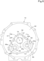
FIG. 6 is a front view of the continuously-variable-transmission casing from which a transmission casing has been removed. -
FIG. 7 is a perspective view of the transmission casing. -
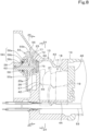
FIG. 8 is a diagram taken along line Z1-Z1 inFIG. 5 . -
FIG. 9 is a diagram taken along line Z4-Z4 inFIG. 8 . -
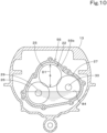
FIG. 10 is a diagram schematically illustrating a transmission, taken along line Z5-Z5 inFIG. 8 . -
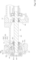
FIG. 11 is a cross-sectional view of a portion where an input gear is located. -
FIG. 12 is a diagram taken along line Z2-Z2 inFIG. 5 . -
FIG. 13 is a diagram taken along line Z3-Z3 inFIG. 5 . -
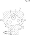
FIG. 14 is a front sectional view of the continuously-variable-transmission casing and illustrates an outflow passage. -
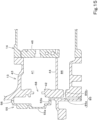
FIG. 15 is a cross-sectional view of the continuously-variable-transmission casing and illustrates the outflow passage. - Example embodiments will now be described with reference to the accompanying drawings, wherein like reference numerals designate corresponding or identical elements throughout the various drawings. The drawings are to be viewed in an orientation in which the reference numerals are viewed correctly.
- Example embodiments of the present invention will be described below while referring to the drawings, as appropriate.
-
FIG. 1 illustrates a side view of a working vehicle 1 according to this embodiment. In this embodiment, a tractor is illustrated as an example of the working vehicle 1. Although the working vehicle 1 is described as being a tractor below, the working vehicle 1 is not limited to a tractor. - As illustrated in
FIG. 1 , the tractor 1 includes an operator's seat 2 where an operator sits. - In the following description, a direction extending forward (direction of an arrow A1 in
FIG. 1 ) from the operator sitting in the operator's seat 2 will be described as a forward direction, and a direction extending rearward (direction of an arrow A2 inFIG. 1 ) from the operator will be described as a rearward direction. A direction extending leftward (toward the viewer ofFIG. 1 ) from the operator will be described as a leftward direction, and a direction extending rightward (away from the viewer ofFIG. 1 ) will be described as a rightward direction. - A direction indicated by an arrow K1 in
FIG. 1 will be described as a front-rear direction. A horizontal direction orthogonal to the front-rear direction K1 will be described as a vehicle-body width direction. In the vehicle-body width direction, a direction extending from the middle toward the right or the left of the tractor 1 will be described as a vehicle-body-width outward direction. In the vehicle-body width direction, a direction extending from the right or the left of the tractor 1 toward the middle of the tractor 1 will be described as a vehicle-body-width inward direction. - As illustrated in
FIG. 1 , the tractor 1 includes avehicle body 3,front wheels 4 located at the left and right of a front portion of thevehicle body 3,rear wheels 5 located at the left and right of a rear portion of thevehicle body 3, and anoperation portion 7 located higher than thevehicle body 3 and including asteering wheel 6, the operator's seat 2, and the like. Thefront wheels 4 are steered wheels that are steerable. In this embodiment, thefront wheels 4 and therear wheels 5 are drive wheels that are drivable. The drive wheels may be therear wheels 5 alone, or may be thefront wheels 4 alone. Thefront wheels 4 and therear wheels 5 define a traveling device that supports thevehicle body 3 in a travelable manner. - As illustrated in
FIG. 1 , thevehicle body 3 includes an engine (prime mover) 8 as a power source, a front frame coupled to theengine 8 and protruding forward from theengine 8, and apower transmitting case 10 coupled to a rear portion of theengine 8 and extending rearward from theengine 8. A power take-off (PTO)shaft 9 that extracts power of theengine 8 to the outside is located at a rear portion of the power transmitting case 10 (vehicle body 3). - In this embodiment, the
engine 8 is a diesel engine. Theengine 8 may be a gasoline engine. The power source may be a prime mover other than an engine. For example, the power source may be an electric motor. - As illustrated in
FIG. 2 , thepower transmitting case 10 includes aflywheel housing 11 coupled to the rear portion of theengine 8, aclutch housing 12 coupled to a rear portion of theflywheel housing 11, a continuously-variable-transmission casing 13 coupled to a rear portion of theclutch housing 12, and a travel-drive transmission casing 14 coupled to a rear portion of the continuously-variable-transmission casing 13. - The
flywheel housing 11 accommodates aflywheel 15 that rotates integrally with a crankshaft of theengine 8. Theclutch housing 12 accommodates a main clutch 16 that intermittently transmits the power of theengine 8 transmitted via theflywheel 15. The continuously-variable-transmission casing 13 accommodates a hydraulic pump (called an HST pump) 18 and a hydraulic motor (called an HST motor) 19 included in a continuously variable transmission (hydro-static continuously variable transmission (HST)) 17 (seeFIGS. 8 and9 ). The travel-drive transmission casing 14 accommodates a travel-drive transmission (seeFIG. 3 ) 20 that speed-changes power output from the continuouslyvariable transmission 17 and transmits the power to the drive wheels. -
FIG. 3 illustrates a primarypower transmitting system 21 that transmits the power of theengine 8. The primarypower transmitting system 21 includes aprimary transmission 22 that distributively transmits the power of theengine 8, a travel-power transmitting system 23 that transmits the power of theengine 8 to the drive wheels (thefront wheels 4 and/or the rear wheels 5), and a PTO-power transmitting system 24 that transmits the power of theengine 8 to thePTO shaft 9. - As illustrated in
FIG. 3 , theprimary transmission 22 includes aninput gear 25 and a pair of transmission gears 26 and 27. As illustrated inFIG. 8 , theinput gear 25 is integrated with ashaft 28 extending forward from theinput gear 25. The power of theengine 8 after theflywheel 15 and the main clutch 16 is transmitted to theinput gear 25 via theshaft 28. As illustrated inFIG. 8 , theinput gear 25 includes a supportedportion 25a protruding rearward from the rotation center. - As illustrated in
FIG. 3 , theinput gear 25 meshes with the pair of transmission gears 26 and 27 and transmits the power to the pair of transmission gears 26 and 27. Thefirst transmission gear 26 as one of the gears in the pair of transmission gears 26 and 27 rotates integrally with afirst transmitting shaft 29. Thesecond transmission gear 27 as the other one of the gears in the pair of transmission gears 26 and 27 rotates integrally with asecond transmitting shaft 30. As illustrated inFIG. 12 , thefirst transmission gear 26 includes a first supportedportion 26a protruding forward and a second supportedportion 26b protruding rearward. As illustrated inFIG. 13 , thesecond transmission gear 27 includes a first supportedportion 27a protruding forward and a second supportedportion 27b protruding rearward. - As illustrated in
FIG. 3 , the travel-power transmitting system 23 includes a continuouslyvariable transmission 17 to which the power from theengine 8 is transmitted, and the travel-drive transmission 20 that speed-changes the power output from the continuouslyvariable transmission 17 and transmits the power to the drive wheels. - First, the continuously
variable transmission 17 will be described. - As mentioned above, the continuously
variable transmission 17 includes theHST pump 18 and theHST motor 19. TheHST pump 18 is driven by the power from theengine 8. TheHST motor 19 is rotationally driven by fluid delivered from theHST pump 18. - As illustrated in
FIG. 4 , theHST pump 18 includes a swash-plate variable displacement pump. The power from theengine 8 is transmitted to theHST pump 18 via the first transmittingshaft 29, and theHST pump 18 is driven by rotational power of the first transmittingshaft 29. With regard to theHST pump 18, the angle of the swash plate is changed by acylinder 31 by operating thecylinder 31 operating in conjunction with the swash plate, whereby the delivery amount and the delivery direction are changeable. TheHST motor 19 is closed-circuit-connected to theHST pump 18 by a pair oftransmission fluid passages HST motor 19 is rotationally driven in the forward rotational direction or the reverse rotational direction by the fluid delivered from theHST pump 18, and outputs, from amotor shaft 33, rotational power steplessly speed-changed and rotated in either of the forward rotational direction and the reverse rotational direction. - The continuously
variable transmission 17 can be set to a neutral state located between the forward rotational state and the reverse rotational state by changing the angle of the swash plate of theHST pump 18. - As illustrated in
FIG. 4 , of the pair oftransmission fluid passages transmission fluid passage charge circuit 34. Thecharge circuit 34 includes high-pressure relief valves transmission fluid passage transmission fluid passage fluid passage 36 between the high-pressure relief valve 35a and the high-pressure relief valve 35b, and areplenishment fluid passage 39 connected to thefluid passage 36. Thefluid passage 36 is supplied with delivery fluid from a supply pump (charge pump) 87. Specifically, thesupply pump 87 is driven by the first transmittingshaft 29 to suction fluid (transmission fluid) in the travel-drive transmission casing 14 via anoil filter 37 and delivers the fluid. The fluid delivered from thesupply pump 87 flows to thefluid passage 36 via anoil filter 38 and thereplenishment fluid passage 39. Thecharge circuit 34 includes acharge relief valve 40 that sets the circuit pressure in thecharge circuit 34, and thecharge relief valve 40 communicates with thereplenishment fluid passage 39. - As illustrated in
FIGS. 8 and9 , the continuously-variable-transmission casing 13 includes ahydraulic transmission chamber 41 that accommodates theHST pump 18 and theHST motor 19. Thehydraulic transmission chamber 41 includes afront wall 42 serving as a front portion of thehydraulic transmission chamber 41, atop wall 43 serving as a top portion, abottom wall 44 serving as a bottom portion, left andright sidewalls port plate 46 serving as a rear portion. - The interior of the
hydraulic transmission chamber 41 is completely filled with fluid. The fluid (purged fluid) from thesupply pump 87 is suppliable into thehydraulic transmission chamber 41. For example, the fluid can be replenished into thehydraulic transmission chamber 41 from thereplenishment fluid passage 39. - Next, the travel-
drive transmission 20 will be described. - As illustrated in
FIG. 3 , the travel-drive transmission 20 includes aplanetary gear mechanism 47, a forward-rearward-travel switching mechanism 48, and asecondary transmission mechanism 49. Theplanetary gear mechanism 47 includes asun gear 47a, a plurality ofplanetary gears 47b provided around thesun gear 47a, acarrier 47c that rotatably supports eachplanetary gear 47b, aring gear 47d that meshes with the plurality ofplanetary gears 47b, and anoutput shaft 47e that outputs power. - Rotational power output from the
motor shaft 33 of theHST motor 19 is input to thesun gear 47a. Rotational power of thesecond transmitting shaft 30 is input to thecarrier 47c. Theplanetary gear mechanism 47 combines a driving force from the continuouslyvariable transmission 17 with a driving force from theengine 8 not affected by a speed-changing operation of the continuouslyvariable transmission 17, and outputs the combined driving force from theoutput shaft 47e to aninput shaft 48a of the forward-rearward-travel switching mechanism 48. - The forward-rearward-
travel switching mechanism 48 outputs the driving force transmitted to theinput shaft 48a from either of a forward-traveloutput gear train 48b that transmits forward-travel power and a rearward-travel gear train 48c that transmits rearward-travel power. The forward-rearward-travel switching mechanism 48 includes a switch clutch 48d that switches the power transmitting mode between a forward-travel transmitting mode and a rearward-travel transmitting mode. - The
secondary transmission mechanism 49 switches power output from anoutput shaft 48e of the forward-rearward-travel switching mechanism 48 to any of a lower speed mode, an intermediate speed mode, and a high speed mode, and outputs the power. The power output from thesecondary transmission mechanism 49 is transmitted to therear wheels 5 via a rear-wheel differential mechanism 50. The power output from thesecondary transmission mechanism 49 is transmitted to thefront wheels 4 via a front-wheel-power extractinggear train 51, aclutch mechanism 52, a front-wheel-power transmitting shaft 53, a front-wheel differential mechanism 54, and the like. - As illustrated in
FIG. 5 , aprimary transmission casing 55 that accommodates theprimary transmission 22 is attached to the front surface of thefront wall 42 of the continuously-variable-transmission casing 13. Thus, the travel-drive transmission casing 14 is coupled to a portion of the continuously-variable-transmission casing 13 opposite from theprimary transmission casing 55. - As illustrated in
FIG. 6 , anannular attachment bracket 56 is provided to protrude forward from the front surface of thefront wall 42 of the continuously-variable-transmission casing 13. As illustrated inFIG. 7 , theprimary transmission casing 55 includes a case front-wall 55a and an outerperipheral wall 55b extending rearward from the outer periphery of the case front-wall 55a. As illustrated inFIG. 8 , theprimary transmission casing 55 is attached to thefront wall 42 of the continuously-variable-transmission casing 13 by setting the rear surface of the outerperipheral wall 55b over the front surface of theattachment bracket 56 of the continuously-variable-transmission casing 13 and fixing the outerperipheral wall 55b to theattachment bracket 56 with bolts. As mentioned above, thefront wall 42 defines the front portion of thehydraulic transmission chamber 41. Therefore, theprimary transmission casing 55 is provided adjacent to thehydraulic transmission chamber 41. - As illustrated in
FIG. 10 , theinput gear 25 is located higher than substantially the middle, in the vehicle-body width direction, of the interior of theprimary transmission casing 55. Thefirst transmission gear 26 is located diagonally rightward of and lower than theinput gear 25. Thesecond transmission gear 27 is located diagonally leftward of and lower than theinput gear 25. Thesecond transmission gear 27 is located such that the upper end thereof is located higher than the upper end of thefirst transmission gear 26. - As illustrated in
FIGS. 8 ,12 , and13 , the gears included in theprimary transmission 22 are located astride the interior of theprimary transmission casing 55 and the inside of theattachment bracket 56. Therefore, the interior of theprimary transmission casing 55 and the space inside the attachment bracket 56 (theprimary transmission casing 55 and apartition wall 57 to be described later) define a hydraulic transmission chamber that accommodates theprimary transmission 22. - As illustrated in
FIG. 7 , the case front-wall 55a includes asupport hole 58, afirst recess 59, and asecond recess 60. Thesupport hole 58 is provided at a position corresponding to the input gear 25 (seeFIG. 11 ). Thefirst recess 59 is provided at a position corresponding to the first transmission gear 26 (seeFIG. 12 ). Thesecond recess 60 is provided at a position corresponding to the second transmission gear 27 (seeFIG. 13 ). Thefirst recess 59 and thesecond recess 60 are recessed forward from the rear surface of the case front-wall 55a. - As illustrated in
FIGS. 8 and11 , theshaft 28 integrated with theinput gear 25 extends through thesupport hole 58. Thesupport hole 58 includes a firstfitting hole 58a, a secondfitting hole 58b, and a small-diameter hole 58c. The firstfitting hole 58a, the secondfitting hole 58b, and the small-diameter hole 58c are provided sequentially from the rear toward the front of theprimary transmission casing 55. A shaft bearing 61 that rotatably supports the shaft 28 (input gear 25) is fitted in the firstfitting hole 58a. Anoil seal 62 that prevents fluid in theprimary transmission casing 55 from leaking outward of theprimary transmission casing 55 via the shaft bearing is fitted in the secondfitting hole 58b. The small-diameter hole 58c has a diameter smaller than a diameter of the secondfitting hole 58b. Accordingly, thefluid seal 62 is prevented from falling out. - As illustrated in
FIG. 12 , a shaft bearing 63 that rotatably supports the first transmission gear 26 (first supportedportion 26a) is fitted in thefirst recess 59. As illustrated inFIG. 13 , a shaft bearing 64 that rotatably supports the second transmission gear 27 (first supportedportion 27a) is fitted in thesecond recess 60. - As illustrated in
FIGS. 6 and8 , an inner portion of theattachment bracket 56 at thefront wall 42 of the continuously-variable-transmission casing 13 defines thepartition wall 57 as a wall that separates thehydraulic transmission chamber 41 and the interior of theprimary transmission casing 55 from each other. Thepartition wall 57 includes amain wall 65 and a blockingmember 66. As illustrated inFIG. 6 , themain wall 65 includes anopen hole 67, afirst insertion hole 68, and asecond insertion hole 69. Theopen hole 67, thefirst insertion hole 68, and thesecond insertion hole 69 extend through themain wall 65. - As illustrated in
FIG. 11 , theopen hole 67 includes afitting hole 70 at a front portion and a stepped hole 71 at a rear portion. A shaft bearing 72 that rotatably supports the input gear 25 (supportedportion 25a) is fitted in thefitting hole 70. The stepped hole 71 has a front portion with a large diameter, and has a rear portion with a small diameter that is smaller than that of the front portion. The blockingmember 66 is fitted in the stepped hole 71. The blockingmember 66 includes a circular-disk-shapeddisk 66a fitted in a small-diameter portion 71a of the stepped hole 71 and anannular flange 66b fitted in a large-diameter portion 71b of the stepped hole 71. An O-ring 73 that prevents fluid in thehydraulic transmission chamber 41 from traveling through between thedisk 66a and the small-diameter portion 71a of the stepped hole 71 and flowing into theprimary transmission casing 55 is fitted to the outer peripheral surface of thedisk 66a. - As illustrated in
FIG. 11 , the blockingmember 66 includes a through-hole 74 provided to extend therethrough in the front-rear direction K1. The through-hole 74 is provided at the center of thedisk 66a. Aplug 75 is inserted and fitted in the through-hole 74. Theplug 75 is fitted to a rear portion of the through-hole 74. - As illustrated in
FIG. 11 , theplug 75 is provided with anorifice 76 extending therethrough in the front-rear direction. Theorifice 76 allows thehydraulic transmission chamber 41 and the interior of theprimary transmission casing 55 to communicate with each other. Thus, fluid flows into theprimary transmission casing 55 from thehydraulic transmission chamber 41 via theorifice 76. - As illustrated in
FIG. 11 , theorifice 76 includes anarrow hole 76a communicating with thehydraulic transmission chamber 41, awide hole 76b having a larger diameter than thenarrow hole 76a and allowing thenarrow hole 76a and the interior of theprimary transmission casing 55 to communicate with each other, and an increasing-diameter hole 76c connecting thenarrow hole 76a and thewide hole 76b to each other and gradually increasing in diameter from thenarrow hole 76a toward thewide hole 76b. - The aforementioned
hydraulic transmission chamber 41 is completely filled with fluid and is supplied with fluid from thesupply pump 87, so that the fluid in thehydraulic transmission chamber 41 is in a pressurized state. Because the fluid passing through theorifice 76 flows into theprimary transmission casing 55 from thenarrow hole 76a via the increasing-diameter hole 76c and thewide hole 76b, the flow speed of the fluid flowing out from theorifice 76 can be alleviated. - As illustrated in
FIG. 11 , theorifice 76 is provided at the height position of the rotation center of theinput gear 25. Afluid passage 77 extends in the front-rear direction K1 through the rotation center of each of theinput gear 25 and theshaft 28 to supply fluid forward of theshaft 28. Thus, theorifice 76 is provided at a position corresponding to thefluid passage 77. - As illustrated in
FIG. 12 , thefirst insertion hole 68 includes a firstfitting hole 68a, a secondfitting hole 68b, and a thirdfitting hole 68c. The firstfitting hole 68a is provided at a front portion of thefirst insertion hole 68. The secondfitting hole 68b is provided at an intermediate portion of thefirst insertion hole 68. The secondfitting hole 68b has a smaller diameter than the firstfitting hole 68a. The thirdfitting hole 68c is provided at a rear portion of thefirst insertion hole 68. The thirdfitting hole 68c has a smaller diameter than the firstfitting hole 68a and a larger diameter than the secondfitting hole 68b. - A shaft bearing 78 that rotatably supports the first transmission gear 26 (second supported
portion 26b) is fitted in the firstfitting hole 68a. Anfluid seal 79 is fitted in the secondfitting hole 68b. A shaft bearing 80 that rotatably supports the first transmittingshaft 29 is fitted in the thirdfitting hole 68c. Thefluid seal 79 prevents fluid from flowing from the shaft bearing 80 (hydraulic transmission chamber 41) toward theprimary transmission casing 55. - As illustrated in
FIG. 13 , thesecond insertion hole 69 includes a firstfitting hole 69a, a secondfitting hole 69b, and a thirdfitting hole 69c. The firstfitting hole 69a is provided at a front portion of thesecond insertion hole 69. The secondfitting hole 69b is provided at an intermediate portion of thesecond insertion hole 69. The secondfitting hole 69b has a smaller diameter than the firstfitting hole 69a. The thirdfitting hole 69c is provided at a rear portion of thesecond insertion hole 69. The thirdfitting hole 69c has a smaller diameter than the firstfitting hole 69a and a larger diameter than the secondfitting hole 69b. - A shaft bearing 81 that rotatably supports the second transmission gear 27 (second supported
portion 27b) is fitted in the firstfitting hole 69a. Anfluid seal 82 is fitted in the secondfitting hole 69b. A shaft bearing 83 that rotatably supports thesecond transmitting shaft 30 is fitted in the thirdfitting hole 69c. Thefluid seal 82 prevents fluid from flowing from the shaft bearing 83 (hydraulic transmission chamber 41) toward theprimary transmission casing 55. - In this embodiment, the
hydraulic transmission chamber 41 and the interior of theprimary transmission casing 55 are separated from each other by thepartition wall 57, theopen hole 67 provided in themain wall 65 of thepartition wall 57 is blocked by the blockingmember 66, the outer peripheral surface of thedisk 66a of the blockingmember 66 is provided with the O-ring 73, and the O-ring 73, thefluid seal 79, and thefluid seal 82 prevent fluid from flowing from thehydraulic transmission chamber 41 toward theprimary transmission casing 55, so that the interior of theprimary transmission casing 55 can be a separate chamber from thehydraulic transmission chamber 41. Furthermore, thehydraulic transmission chamber 41 and the interior of theprimary transmission casing 55 can be separated from each other to prevent the fluid in thehydraulic transmission chamber 41 from flowing into theprimary transmission casing 55 through or in any portion except for theorifice 76. - For example, assuming that the interior of the
primary transmission casing 55 is in a state where the fluid flows to and from thehydraulic transmission chamber 41 and is completely filled with the fluid, the gear stirring resistance inside theprimary transmission casing 55 is large. When the gear stirring resistance inside theprimary transmission casing 55 is large, horsepower loss occurs due to the large gear stirring resistance. - In contrast, in this embodiment, the interior of the
primary transmission casing 55 is a separate chamber from thehydraulic transmission chamber 41, so that the height of afluid level 84 of the fluid inside theprimary transmission casing 55 can be reduced to be located at a vertically intermediate portion (intermediate portion in the up-down direction), as illustrated inFIG. 10 . Accordingly, the gear stirring resistance inside theprimary transmission casing 55 can be reduced. Consequently, horsepower loss can be reduced. - As illustrated in
FIGS. 14 and15 , the continuously-variable-transmission casing 13 is provided with anoutflow passage 85 that causes the fluid inside theprimary transmission casing 55 to flow out. Theoutflow passage 85 is configured to cause the fluid inside theprimary transmission casing 55 to flow out into the travel-drive transmission casing 14. Specifically, theoutflow passage 85 includes afirst fluid passage 85a extending in the up-down direction and asecond fluid passage 85b extending rearward from an intermediate portion of thefirst fluid passage 85a. The upper end of thefirst fluid passage 85a is open to the inside of theattachment bracket 56. Thus, thefirst fluid passage 85a (outflow passage 85) communicates with the interior of theprimary transmission casing 55. - As illustrated in
FIG. 15 , an upper-end opening of thefirst fluid passage 85a is located at substantially the same height as the height position of the bottom of theprimary transmission casing 55. Thus, theoutflow passage 85 is configured to cause the fluid inside theprimary transmission casing 55 to flow out from the bottom. - As illustrated in
FIG. 15 , thesecond fluid passage 85b allows thefirst fluid passage 85a and acavity 86 provided in the continuously-variable-transmission casing 13 to communicate with each other. Thecavity 86 is provided lower than thebottom wall 44 serving as the bottom of thehydraulic transmission chamber 41 in the continuously-variable-transmission casing 13. Thecavity 86 is open rearward and communicates with the interior of the travel-drive transmission casing 14. - Therefore, the fluid inside the
primary transmission casing 55 flows through theoutflow passage 85 and thecavity 86 from the bottom of theprimary transmission casing 55 and flows into the travel-drive transmission casing 14. Because the interior of theprimary transmission casing 55 communicates with the interior of the travel-drive transmission casing 14, the height of thefluid level 84 of the fluid inside theprimary transmission casing 55 is substantially the same as the height of the fluid level of the fluid inside the travel-drive transmission casing 14. Specifically, theoutflow passage 85 and thecavity 86 define a communication passage that allows the interior of theprimary transmission casing 55 and the interior of the travel-drive transmission casing 14 to communicate with each other, whereby the height of thefluid level 84 of the fluid inside theprimary transmission casing 55 can be set to the height of the vertically intermediate portion of theprimary transmission casing 55. - The fluid flow amount (hole diameter) of the
orifice 76 is set such that thehydraulic transmission chamber 41 is completely filled with fluid and that thefluid level 84 of the fluid inside theprimary transmission casing 55 is located at the vertically intermediate portion inside theprimary transmission casing 55. - Because the
hydraulic transmission chamber 41 is supplied with purged fluid delivered from thesupply pump 87, the cleanliness of the fluid inside thehydraulic transmission chamber 41 can be enhanced. Furthermore, because thehydraulic transmission chamber 41 is supplied with fluid delivered from thesupply pump 87 and traveled through theoil filter 38, the cleanliness of the fluid inside thehydraulic transmission chamber 41 can be further enhanced. - The fluid inside the primary transmission casing 55 (hydraulic transmission chamber) flows toward the travel-drive transmission casing 14 from the bottom of the
primary transmission casing 55, and the fluid in thehydraulic transmission chamber 41 flows into theprimary transmission casing 55 from theorifice 76, thereby achieving purging of the fluid in theprimary transmission casing 55. - The structure for providing the
aforementioned orifice 76 is not limited to the structure according to this embodiment. For example, theorifice 76 may be provided not in theplug 75 but directly in the partition wall that separates thehydraulic transmission chamber 41 and the interior of theprimary transmission casing 55 from each other. - Although the
orifice 76 is provided at the height position of the rotation center of theinput gear 25 in the above embodiment, the position where theorifice 76 is provided is not limited. For example, theorifice 76 may be provided higher than the height of thefluid level 84 of the fluid inside theprimary transmission casing 55. Furthermore, theorifice 76 may be provided at a height position within the range of a tip diameter D 1 (seeFIG. 10 ) of theinput gear 25. - The
open hole 67 does not have to be provided with the stepped hole 71 so long as theopen hole 67 includes thefitting hole 70. In other words, the rear portion of theopen hole 67 may be blocked. In this case, the blockingmember 66 is not provided. - Example embodiments of the present invention provide working vehicles 1 according to the following items.
- (Item 1) A working vehicle 1 comprising a
hydraulic transmission chamber 41 to accommodate ahydraulic pump 18 and ahydraulic motor 19 driven by fluid delivered from thehydraulic pump 18, and aprimary transmission casing 55 to accommodate aprimary transmission 22 including aninput gear 25 to receive power from aprime mover 8 and atransmission gear 26 to transmit power from theinput gear 25 to thehydraulic pump 18, theprimary transmission casing 55 being adjacent to thehydraulic transmission chamber 41, wherein an interior of theprimary transmission casing 55 is separated from thehydraulic transmission chamber 41. - In the working vehicle 1 according to item 1, the interior of the
primary transmission casing 55 adjacent to thehydraulic transmission chamber 41 is a separate chamber from thehydraulic transmission chamber 41, so that the height of thefluid level 84 inside theprimary transmission casing 55 can be reduced. Accordingly, the gear stirring resistance inside theprimary transmission casing 55 can be reduced. Consequently, horsepower loss can be reduced. - (Item 2) The working vehicle 1 according to item 1, further comprising an
orifice 76 to allow thehydraulic transmission chamber 41 and the interior of theprimary transmission casing 55 to communicate with each other, wherein thehydraulic transmission chamber 41 and the interior of theprimary transmission casing 55 are separated from each other such that fluid in thehydraulic transmission chamber 41 does not flow into theprimary transmission casing 55 through or in any portion except for theorifice 76. - In the working vehicle 1 according to item 2, the height of the
fluid level 84 inside theprimary transmission casing 55 can be reduced, so that the gear stirring resistance inside theprimary transmission casing 55 can be reduced. - (Item 3) The working vehicle 1 according to item 2, further comprising a
supply pump 87 operable to replenish thehydraulic transmission chamber 41 with purged fluid, and anoutflow passage 85 to cause fluid inside theprimary transmission casing 55 to flow out, wherein a fluid flow amount of theorifice 76 is determined such that thehydraulic transmission chamber 41 is completely filled with fluid and a fluid level of the fluid inside theprimary transmission casing 55 is located at a vertically intermediate portion inside theprimary transmission casing 55. - In the working vehicle 1 according to
item 3, the cleanliness of the fluid in thehydraulic transmission chamber 41 and theprimary transmission casing 55 can be enhanced. Furthermore, with thehydraulic transmission chamber 41 and theprimary transmission casing 55 communicating with each other through theorifice 76, the height of the fluid level in theprimary transmission casing 55 can be maintained at the height position of the vertically intermediate portion (i.e., intermediate portion in the up-down direction). - (Item 4) The working vehicle 1 according to
item 3, further comprising a continuously-variable-transmission casing 13 including thehydraulic transmission chamber 41, and a travel-drive transmission casing 14 to accommodate a travel-drive transmission 20 that is configured to speed-change power output from thehydraulic motor 19 and transmit the speed-changed power to adrive wheel transmission casing 13 opposite from theprimary transmission casing 55, wherein thesupply pump 87 is configured to replenish thehydraulic transmission chamber 41 with fluid sucked from the inside of the travel-drive transmission casing 14 via anoil filter 37, and theoutflow passage 85 is configured to cause fluid inside theprimary transmission casing 55 to flow out into the travel-drive transmission casing 14. - In the working vehicle 1 according to
item 4, the fluid in the travel-drive transmission casing 14 is purged and circulated, so that the cleanliness of the fluid in thehydraulic transmission chamber 41 and theprimary transmission casing 55 can be maintained. - (Item 5) The working vehicle 1 according to any one of items 2 to 4, wherein the
input gear 25 is located at an upper portion inside theprimary transmission casing 55 and higher than thefirst transmission gear 26, and theorifice 76 is located at a height within a range of a tip diameter D1 of theinput gear 25. - In the working vehicle 1 according to
item 5, the fluid flowing out from theorifice 76 flows out to theprimary transmission casing 55 from the upper portion of theprimary transmission casing 55, so that the fluid can be favorably supplied into theprimary transmission casing 55 in which the height of thefluid level 84 is set to the vertically intermediate portion. - (Item 6) The working vehicle 1 according to any one of items 2 to 5, further comprising a
plug 75 to block a through-hole 74 extending through awall 57 and to separate thehydraulic transmission chamber 41 and the interior of theprimary transmission casing 55 from each other, wherein theorifice 76 is provided in theplug 75. - In the working vehicle 1 according to
item 6, a case where the hole diameter of theorifice 76 is not appropriate can be dealt with by replacing theplug 75, and the fluid flow amount of theorifice 76 can be set readily. - (Item 7) The working vehicle 1 according to any one of items 2 to 6, wherein the
orifice 76 includes anarrow hole 76a communicating with thehydraulic transmission chamber 41, and awide hole 76b having a diameter larger than a diameter of thenarrow hole 76a such as to allow thenarrow hole 76a and the interior of thetransmission casing 55 to communicate with each other. - In the working vehicle 1 according to
item 7, the flow speed of the fluid flowing out from thenarrow hole 76a can be alleviated. - (Item 8) The working vehicle 1 according to
item 7, wherein theorifice 76 includes an increasing-diameter hole 76c that connects thenarrow hole 76a and thewide hole 76b to each other, the increasing-diameter hole 76c gradually increasing in diameter from thenarrow hole 76a toward thewide hole 76b. - In the working vehicle 1 according to
item 8, the flow speed of the fluid flowing out from thenarrow hole 76a can be alleviated. - While example embodiments of the present invention have been described above, it is to be understood that variations and modifications will be apparent to those skilled in the art without departing from the scope and spirit of the present invention. The scope of the present invention, therefore, is to be determined solely by the following claims.
Claims (8)
- A working vehicle (1) comprising:a hydraulic transmission chamber (41) to accommodate a hydraulic pump (18) and a hydraulic motor (19) driven by fluid delivered from the hydraulic pump (18); anda primary transmission casing (55) to accommodate a primary transmission (22) including an input gear (25) to receive power from a prime mover (8) and a transmission gear (26) to transmit power from the input gear (25) to the hydraulic pump (18), the primary transmission casing (55) being adjacent to the hydraulic transmission chamber (41), whereinan interior of the primary transmission casing (55) is separated from the hydraulic transmission chamber (41).
- The working vehicle (1) according to claim 1, further comprising:an orifice (76) to allow the hydraulic transmission chamber (41) and the interior of the primary transmission casing (55) to communicate with each other, whereinthe hydraulic transmission chamber (41) and the interior of the primary transmission casing (55) are separated from each other such that fluid in the hydraulic transmission chamber (41) does not flow into the primary transmission casing (55) through or in any portion except for the orifice (76).
- The working vehicle (1) according to claim 2, further comprising:a supply pump (87) operable to replenish the hydraulic transmission chamber (41) with purged fluid; andan outflow passage (85) to cause fluid inside the primary transmission casing (55) to flow out, whereina fluid flow amount of the orifice (76) is determined such that the hydraulic transmission chamber (41) is completely filled with fluid and a fluid level of the fluid inside the primary transmission casing (55) is located at a vertically intermediate portion inside the primary transmission casing (55).
- The working vehicle (1) according to claim 3, further comprising:a continuously-variable-transmission casing (13) including the hydraulic transmission chamber (41); anda travel-drive transmission casing (14) to accommodate a travel-drive transmission (20) that is configured to speed-change power output from the hydraulic motor 19 and transmit the speed-changed power to a drive wheel (4, 5), the travel-drive transmission casing being coupled to a portion of the continuously-variable-transmission casing (13) opposite from the primary transmission casing (55), whereinthe supply pump (87) is configured to replenish the hydraulic transmission chamber (41) with fluid sucked from the inside of the travel-drive transmission casing (14) via an oil filter (37), andthe outflow passage (85) is configured to cause fluid inside the primary transmission casing (55) to flow out into the travel-drive transmission casing (14).
- The working vehicle (1) according to any one of claims 2 to 4, whereinthe input gear (25) is located at an upper portion inside the primary transmission casing (55) and higher than the first transmission gear (26), andthe orifice (76) is located at a height within a range of a tip diameter (D 1) of the input gear (25).
- The working vehicle (1) according to any one of claims 2 to 5, further comprising:a plug (75) to block a through-hole (74) extending through a wall (57) and to separate the hydraulic transmission chamber (41) and the interior of the primary transmission casing (55) from each other, whereinthe orifice (76) is provided in the plug (75).
- The working vehicle (1) according to any one of claims 2 to 6, wherein
the orifice (76) includes:a narrow hole (76a) communicating with the hydraulic transmission chamber (41); anda wide hole (76b) having a diameter larger than a diameter of the narrow hole (76a) such as to allow the narrow hole (76a) and the interior of the transmission casing (55) to communicate with each other. - The working vehicle (1) according to claim 7, wherein
the orifice (76) includes an increasing-diameter hole (76c) that connects the narrow hole (76a) and the wide hole (76b) to each other, the increasing-diameter hole (76c) gradually increasing in diameter from the narrow hole (76a) toward the wide hole (76b).
Applications Claiming Priority (1)
| Application Number | Priority Date | Filing Date | Title |
|---|---|---|---|
| JP2023216818A JP2025099861A (en) | 2023-12-22 | 2023-12-22 | Working vehicle |
Publications (1)
| Publication Number | Publication Date |
|---|---|
| EP4575268A1 true EP4575268A1 (en) | 2025-06-25 |
Family
ID=93924287
Family Applications (1)
| Application Number | Title | Priority Date | Filing Date |
|---|---|---|---|
| EP24220174.7A Pending EP4575268A1 (en) | 2023-12-22 | 2024-12-16 | Working vehicle |
Country Status (3)
| Country | Link |
|---|---|
| US (1) | US20250207659A1 (en) |
| EP (1) | EP4575268A1 (en) |
| JP (1) | JP2025099861A (en) |
Citations (4)
| Publication number | Priority date | Publication date | Assignee | Title |
|---|---|---|---|---|
| DE10151019A1 (en) * | 2000-10-19 | 2002-07-11 | Zahnradfabrik Friedrichshafen | Drive assembly esp. for motor vehicles and mobile working machinery has several housing sections, one with low oil level containing intake tube leading into ejector in oil circuit return |
| US20060179973A1 (en) * | 2003-03-10 | 2006-08-17 | Yanmar Co., Ltd. | Baffle plate and transmission |
| US20120046138A1 (en) * | 2010-08-19 | 2012-02-23 | Kubota Corporation | Power Train for Work Vehicle |
| US20230204093A1 (en) * | 2021-12-24 | 2023-06-29 | Kubota Corporation | Work vehicle |
-
2023
- 2023-12-22 JP JP2023216818A patent/JP2025099861A/en active Pending
-
2024
- 2024-12-16 US US18/981,879 patent/US20250207659A1/en active Pending
- 2024-12-16 EP EP24220174.7A patent/EP4575268A1/en active Pending
Patent Citations (5)
| Publication number | Priority date | Publication date | Assignee | Title |
|---|---|---|---|---|
| DE10151019A1 (en) * | 2000-10-19 | 2002-07-11 | Zahnradfabrik Friedrichshafen | Drive assembly esp. for motor vehicles and mobile working machinery has several housing sections, one with low oil level containing intake tube leading into ejector in oil circuit return |
| US20060179973A1 (en) * | 2003-03-10 | 2006-08-17 | Yanmar Co., Ltd. | Baffle plate and transmission |
| US20120046138A1 (en) * | 2010-08-19 | 2012-02-23 | Kubota Corporation | Power Train for Work Vehicle |
| JP2012040944A (en) | 2010-08-19 | 2012-03-01 | Kubota Corp | Transmission device for tractor |
| US20230204093A1 (en) * | 2021-12-24 | 2023-06-29 | Kubota Corporation | Work vehicle |
Also Published As
| Publication number | Publication date |
|---|---|
| JP2025099861A (en) | 2025-07-03 |
| US20250207659A1 (en) | 2025-06-26 |
Similar Documents
| Publication | Publication Date | Title |
|---|---|---|
| EP2325525B1 (en) | Transmission | |
| US7374010B2 (en) | Transmission for a working vehicle and vehicle | |
| US7559865B2 (en) | Transmission apparatus for a working vehicle | |
| US7775309B2 (en) | Pump unit | |
| WO2002064999A1 (en) | Hydromechanical speed-change device and vehicle having speed change device mounted thereon | |
| EP1363050A1 (en) | Power unit | |
| GB2373773A (en) | Frameless working vehicle including a hydrostatic transmission | |
| US12017528B2 (en) | Traveling transmission device of tractor | |
| JP7660495B2 (en) | Work vehicle | |
| US7163077B2 (en) | Frame structure of a vehicle | |
| US20120297757A1 (en) | Hydrostatic Stepless Transmission | |
| JP2018009692A (en) | HMT unit and HMT structure | |
| US20250207659A1 (en) | Working vehicle | |
| US20070169475A1 (en) | Hst | |
| JP2008202721A (en) | Transmission | |
| JP2021054392A (en) | Travel transmission device of tractor | |
| JP2008201303A (en) | Transmission | |
| EP3842663B1 (en) | Work machine | |
| JP7584398B2 (en) | Work vehicle | |
| JP2008202712A (en) | Transmission | |
| JP2024180048A (en) | Work vehicle | |
| KR102622444B1 (en) | Transmission for work vehicle | |
| JP2008201285A (en) | Transmission | |
| EP4389486A1 (en) | Vehicle | |
| JP2018053999A (en) | HMT structure |
Legal Events
| Date | Code | Title | Description |
|---|---|---|---|
| PUAI | Public reference made under article 153(3) epc to a published international application that has entered the european phase |
Free format text: ORIGINAL CODE: 0009012 |
|
| STAA | Information on the status of an ep patent application or granted ep patent |
Free format text: STATUS: REQUEST FOR EXAMINATION WAS MADE |
|
| 17P | Request for examination filed |
Effective date: 20241219 |
|
| AK | Designated contracting states |
Kind code of ref document: A1 Designated state(s): AL AT BE BG CH CY CZ DE DK EE ES FI FR GB GR HR HU IE IS IT LI LT LU LV MC ME MK MT NL NO PL PT RO RS SE SI SK SM TR |