EP4575267A1 - Strain wave gear differential with high gear reduction - Google Patents
Strain wave gear differential with high gear reduction Download PDFInfo
- Publication number
- EP4575267A1 EP4575267A1 EP24222296.6A EP24222296A EP4575267A1 EP 4575267 A1 EP4575267 A1 EP 4575267A1 EP 24222296 A EP24222296 A EP 24222296A EP 4575267 A1 EP4575267 A1 EP 4575267A1
- Authority
- EP
- European Patent Office
- Prior art keywords
- input shaft
- aft
- spline
- flex spline
- drive
- Prior art date
- Legal status (The legal status is an assumption and is not a legal conclusion. Google has not performed a legal analysis and makes no representation as to the accuracy of the status listed.)
- Pending
Links
Images


Classifications
-
- F—MECHANICAL ENGINEERING; LIGHTING; HEATING; WEAPONS; BLASTING
- F16—ENGINEERING ELEMENTS AND UNITS; GENERAL MEASURES FOR PRODUCING AND MAINTAINING EFFECTIVE FUNCTIONING OF MACHINES OR INSTALLATIONS; THERMAL INSULATION IN GENERAL
- F16H—GEARING
- F16H49/00—Other gearings
- F16H49/001—Wave gearings, e.g. harmonic drive transmissions
-
- F—MECHANICAL ENGINEERING; LIGHTING; HEATING; WEAPONS; BLASTING
- F16—ENGINEERING ELEMENTS AND UNITS; GENERAL MEASURES FOR PRODUCING AND MAINTAINING EFFECTIVE FUNCTIONING OF MACHINES OR INSTALLATIONS; THERMAL INSULATION IN GENERAL
- F16H—GEARING
- F16H35/00—Gearings or mechanisms with other special functional features
- F16H35/008—Gearings or mechanisms with other special functional features for variation of rotational phase relationship, e.g. angular relationship between input and output shaft
-
- F—MECHANICAL ENGINEERING; LIGHTING; HEATING; WEAPONS; BLASTING
- F16—ENGINEERING ELEMENTS AND UNITS; GENERAL MEASURES FOR PRODUCING AND MAINTAINING EFFECTIVE FUNCTIONING OF MACHINES OR INSTALLATIONS; THERMAL INSULATION IN GENERAL
- F16H—GEARING
- F16H49/00—Other gearings
- F16H49/001—Wave gearings, e.g. harmonic drive transmissions
- F16H2049/003—Features of the flexsplines therefor
Definitions
- the first and second input shafts are configured to counter-rotate relative to each other.
- the output shaft is configured to counter-rotate relative to the first input shaft and co-rotate relative to the second input shaft.
- the splines are axially aligned with each other.
- the first spline of the first flex spline defines a first inverted tooth set (IT1); the second spline of the second flex spline defines a first conventional tooth set (CT1); and the third spline of the circular gear defines a second inverted tooth set (IT2) that mesh with the first inverted tooth set (IT1); and the fourth spline of the circular gear defines a second conventional tooth set (CT2) that mesh with the first conventional tooth set (CT1).
- a third output speed (SO3) of the output shaft is proportional to a speed summed differential, which is proportional to a differential between SI2 multiplied by DCGR and SI1 multiplied by DIGR.
- the first flex spline is a silk-hat shaped flex spline that extends from a forward end to an aft end, and wherein the forward end of the first flex spline defines the ground ring and the aft end of the first flex spline defines the first spline.
- the second flex spline is a cup shaped flex spline that extends from a forward end to an aft end, and wherein the forward end of the second flex spline defines the second spline and the aft end of the second flex spline is a radial disk that defines a center aperture.
- the first input shaft extends from a froward end to an aft end and has an inner surface and an outer surface; the forward end of the first input shaft is axially adjacent to the ground ring and the aft end of the first input shaft is aft of the aft end of the first flex spline and the second flex spline; and the inner surface of the first input shaft includes an axially intermediate portion that defines the first wave generator.
- the drive includes a forward outer bearing disposed against the outer surface of the first input shaft, at the forward end of the first input shaft; and an aft outer bearing against the outer surface of the first input shaft, at the aft end of the first input shaft.
- the second input shaft extends from a forward end to an aft end and defines a forward portion, an aft portion and an intermediate portion; the forward portion of the second input shaft extends from the forward end of the second input shaft to the ground ring and defines a solid shaft having a first forward diameter; the intermediate portion of the second input shaft has an intermediate diameter that is greater than the first forward diameter; and the aft portion of the second input shaft has an axial span that is the same as the intermediate portion of the first input shaft and is axially aligned with the intermediate portion of the first input shaft, and wherein the aft portion of the second input shaft has a first aft diameter that is greater than the intermediate diameter, and wherein the aft portion of the second input shaft defines the second wave generator.
- the drive includes a forward inner bearing located between the intermediate portion of the second input shaft and the first flex spline.
- the second input shaft defines a blind hole that extends forward from the aft end of the second input shaft, along the aft portion and the intermediate portion of the second input shaft; and the blind hole has an aft hole diameter along the aft portion of the second input shaft and a forward hole diameter along the intermediate portion of the second input shaft that is smaller than the aft hole diameter.
- the output shaft extends from a forward end to an aft end and defines a forward portion, an aft portion, and flange between the forward portion and the aft portion;
- the flange has a flange diameter and the flange is connected to the radial disk of the second flex spline, wherein the flange has a flange thickness so that an aft surface of the flange is axially aligned with the aft end of the first input shaft;
- the aft portion of the output shaft has a second aft diameter that is smaller than the flange diameter;
- the forward portion of the output shaft defines a connecting shaft that extends through the center aperture in the second flex spline, into the blind hole in the second input shaft, wherein the forward portion of the output shaft has a second forward diameter that is smaller than the second aft diameter, and the center aperture in the second flex spline is sized for receiving the forward portion of the output shaft.
- the drive includes an aft inner bearing disposed in the blind hole of the second input shaft, between the forward portion of the output shaft and the aft portion of the second input shaft.
- the drive includes an aft drive bearing surrounding a portion of the aft portion of the output shaft, wherein the aft drive bearing is located against the portion of the output shaft.
- the drive 100 is configuration with a strain wave gear differential with an inverted strain wave generator 140 and a conventional strain wave generator 170 as input to a shared opposed splined circular gear 230. That is, the drive 100 is a harmonic drive that connects a control surface 50 of an aircraft 60, such a flap, to a stationary structure 70 of the aircraft 60 such as frame member. As indicated below, the drive 100 has redundant motive inputs, i.e., first and second input shafts, 130, 160 for a single output, i.e., an output shaft 180. Each of the input shafts 130, 160 is respectively coupled to first and second motors 80, 90 so that in the event of a complete or partial failure mode of one of the motors 80, 90, the control surface 50 can be operated as required, e.g., during flight.
- first and second input shafts, 130, 160 is respectively coupled to first and second motors 80, 90 so that in the event of a complete or partial failure mode of one of the motors 80, 90, the control surface 50 can be operated as
- the drive 100 includes a ground ring 110 that connects to the stationary structure 70.
- a first flex spline 120 extends axially from (e.g., is coupled to) the ground ring 110.
- the first input shaft 130 is radially exterior to the first flex spline 120.
- the first input shaft 130 includes a first wave generator 140 that engages the first flex spline 120.
- a second flex spline 150 is radially within (interior to) the first flex spline 120 and rotationally coupled to the first flex spline 120.
- the second input shaft 160 is radially within the second flex spline 120.
- the second input shaft 160 includes a second wave generator 170 that engages the second flex spline 150.
- the output shaft 180 is coupled to the second flex spline 150.
- the first and second input shafts 130, 160 are configured to rotate separately or simultaneously.
- the output shaft 180 is configured to rotate with rotation of either or both of the first and second input shafts 130, 160.
- the first and second input shafts 130, 160 are configured to counter-rotate relative to each other.
- the output shaft 180 is configured to counter-rotate relative to the first input shaft 130 and co-rotate relative to the second input shaft 160.
- a first wave generator bearing 190 is between the first wave generator 140 and the first flex spline 120.
- a second wave generator bearing 200 is between the second wave generator 170 and the second flex spline 150.
- the first flex spline 120 includes a first spline 210 that faces radially inward.
- the second flex spline 150 includes a second spline 220 that faces radially outward.
- the circular gear 230 includes a third spline 240 that faces radially outward and engage the first spline 210.
- the circular gear 230 includes a fourth spline 250 that faces radially inward and engages the second spline 220.
- the splines 210-250 are axially aligned with each other and has a same axial span as each other.
- the first spline 210 of the first flex spline 120 defines a first inverted tooth set (IT1).
- the second flex spline 150 of the second flex spline 150 defines a first conventional tooth set (CT1).
- the third spline 240 of the circular gear 230 defines a second inverted tooth set (IT2) that meshes with the first inverted tooth set (IT1).
- the fourth spline 250 of the circular gear 230 defines a second conventional tooth set (CT2) that meshes with the first conventional tooth set (CT1).
- IT1 and IT2 differ from each other and CT1 and CT2 differ from each other.
- DCGR drive conventional gear ratio
- a third output speed SO3 of the output shaft 180 is proportional to a speed summed differential SSD.
- the speed summed differential SSD is proportional to a difference between SI2 multiplied by DCGR and SI1 multiplied by DIGR. This accounts for a difference between SO1 and SO2 that would result if the brakes were selectively engaged.
- the first motor 80 would normally control operation of the first input shaft 130 to drive the output shaft 180 and obtain desired rotational position of the control surface 50. However, if the first motor 80 were to entirely fail, the configuration of FIG. 3 results is executed, such that operation of the second motor 90 drives the second input shaft 160 to provide for rotation of the output shaft 180. If the first motor 80 were to partially fail and either overspeed or under-speed, the configuration of FIG. 5 is executed, with the second motor 90 driving the second input shaft 160 while the first motor 80 drives the first input shaft 130.
- the first input shaft 130 extends from a forward end 130A to an aft end 130B and has an outer surface 130C and an inner surface 130D.
- the forward end 130A of the first input shaft 130 is axially adjacent to the ground ring 110 and the aft end 130B of the first input shaft 130 is aft of the aft end 120B of the first flex spline 120 and the aft end 150B of the second flex spline 150.
- the inner surface 130D of the first input shaft 130 includes an axially intermediate portion 130E that defines the first wave generator 140.
- a forward outer bearing 270 is disposed against the outer surface 130C of the first input shaft 130, at the forward end 130A of the first input shaft 130.
- An aft outer bearing 280 is disposed against the outer surface 130C of the first input shaft 130, at the aft end 130B of the first input shaft 130.
- a ground ring diameter Dr defines an outer diameter of the drive 100, and substantially matches an outer diameter defined by the bearings 270, 280.
- the first input shaft 130 has a next larger diameter, being slightly smaller than the ground ring and its outer boundary defines a body 105 of the drive 100 from which the second input shaft 160 and the output shaft 180 extend axially.
- Holes 111 in the ground ring 110 receive fasteners 112 which may be bolts that mount the drive 100 to a stationary structure.
- the second input shaft 160 extends from a forward end 160A to an aft end 160B and defines a forward portion 162, an aft portion 164 and an intermediate portion 166 therebetween.
- the forward portion 162 of the second input shaft 160 extends from the forward end 160A of the second input shaft 160 to the ground ring 110 and defines a solid shaft having a first forward diameter Df1.
- the intermediate portion 166 of the second input shaft 160 has an intermediate diameter Di that is greater than the first forward diameter Df1.
- a forward inner bearing 290 is located between the intermediate portion 166 of the second input shaft 160 and the first flex spline 120.
- An axial span (length) of the aft portion 164 of the second input shaft 160 is the same as the intermediate portion 130E of the first input shaft 130.
- the aft portion 164 of the second input shaft 160 is axially aligned with the intermediate portion 130E of the first input shaft 130.
- a first aft diameter Da1 is defined by the aft portion 164 of the second input shaft 160 that is greater than the intermediate diameter Di.
- the second wave generator 170 is defined by the aft portion 164 of the second input shaft 160.
- the second input shaft 160 defines a blind hole 168 that extends forward from the aft end 160B of the second input shaft 160, along the aft portion 164 and intermediate portion 166 of the second input shaft 160. That is, the blind hole 168 defines a forward portion 168A and an aft portion 168B, where the aft portion 168B defines an aperture 168C of the blind hole 168.
- the blind hole 168 has an aft hole diameter Dah along the aft portion 164 of the second input shaft 160, i.e., along its aft portion 168B.
- the blind hole 168 has a forward hole diameter Dfh along the intermediate portion 166 of the second input shaft 160, i.e., along its forward portion 168A, that is smaller than the aft hole diameter Dah.
- the output shaft 180 extends from a forward end 180A to an aft end 180B and defines a forward portion 182, an aft portion 184, and flange 186 between the forward portion 182 and the aft portion 184.
- the flange 186 has a flange diameter Df and the flange 186 is connected to the radial disk 260 of the second flex spline 150, e.g., via fasteners 300 such as bolts.
- the flange 186 has a flange thickness Tf so that an aft surface 186A of the flange 186 is axially aligned with the aft end 130B of the first input shaft 130.
- the aft portion 184 of the output shaft 180 has a second aft diameter Da2 that is smaller than the flange diameter Df.
- the forward portion 180B of the output shaft 180 defines a connecting shaft that extends through the center aperture 270 in the second spline 220 and into the blind hole 168 in the second input shaft 160.
- the forward portion 182 of the output shaft 180 has a second forward diameter Df2 that is smaller than the second aft diameter Da2.
- the center aperture 270 in the second flex spline 150 is sized for receiving the forward portion 182 of the output shaft 180, to pass therethrough.
- An aft inner bearing 310 is disposed in the blind hole 168 of the second input shaft 160.
- the aft inner bearing 310 is located between the forward portion 182 of the output shaft 180 and the aft portion 164 of the second input shaft 160.
- An aft drive bearing 320 surrounds a portion of the aft portion 184 of the output shaft 180.
- the aft drive bearing 320 is located against the flange 186 of the output shaft 180.
- a forward clip 330 extends along a forward end of circular gear 230, the second flex spline 150, the second wave generator bearing 200 and the aft portion 164 of the second input shaft 160.
- An aft clip 340 extends along an aft end of the circular gear 230, the first flex spline 120, and the first wave generator bearing 190. The clips maintain the axial alignment of the drive components.
- Each of the bearings disclosed above may be a ball bearing.
- the disclosed drive 100 provides redundant motive elements, i.e., input shafts, such that a combination of motive input provides a speed sum differential as the output.
- the drive 100 provides a high gear ratio to a small volume differential.
- the drive provides fault tolerance, i.e., if a motor connected to the first input shaft 130 fails entirely or partially, a second motor connected to the second input shaft 160 may engage so that an output can be manipulated as required.
- the drive 100 provides an integrated differential and gear reduction design that optimizes weight, volume, cost, and reliability.
Landscapes
- Engineering & Computer Science (AREA)
- General Engineering & Computer Science (AREA)
- Mechanical Engineering (AREA)
- Retarders (AREA)
Abstract
A harmonic drive, having: a ground ring (110); a first flex spline (120) extending axially from the ground ring; a first input shaft (SI1) that is radially exterior to the first flex spline, the first input shaft includes a first wave generator (140) that engages the first flex spline; a second flex spline (150), radially within the first flex spline and rotationally coupled to the first flex spline, a second input shaft (SI2) that is radially within the second flex spline, the second input shaft includes a second wave generator (170) that engages the second flex spline; an output shaft (SO) coupled to the second flex spline, the first flex spline includes a first spline (210) that faces radially inward; the second flex spline includes a second spline (220) that faces radially outward; a circular gear (230) having a third spline (240) that face outwardly and engages the first spline; a fourth spline (250) that faces radially inward and engages the second spline.
Description
- The embodiments are directed to harmonic drives and more specifically to a drive configured as a strain wave gear differential with a high gear reduction.
- Some actuation systems, such as found in an aircraft to move a control surface, require a dual motor drive, for redundancy, to drive a single output. A differential gear configuration may be utilized to achieve this objective. A relatively small gear reduction can be achieved within the differential gear configuration. However, typically an additional larger reduction gear is required downstream of the differential gear configuration to obtain the desired rotational output of the control surface, requiring additional gear components. The differential gear and downstream reduction gear can add significant weight, volume and failure modes.
- Disclosed is a harmonic drive, including: a ground ring; a first flex spline extending axially from the ground ring; a first input shaft that is radially exterior to the first flex spline, wherein the first input shaft includes a first wave generator that engages the first flex spline; a second flex spline, radially within the first flex spline and rotationally coupled to the first flex spline, a second input shaft that is radially within the second flex spline, wherein the second input shaft includes a second wave generator that engages the second flex spline; an output shaft coupled to the second flex spline, wherein: the first flex spline includes a first spline that faces radially inward; the second flex spline includes a second spline that faces radially outward; and the drive further includes a circular gear that includes: a third spline that face outwardly and engages the first spline; and a fourth spline that faces radially inward and engages the second spline.
- In embodiments, the first and second input shafts are configured to counter-rotate relative to each other.
- In embodiments, the output shaft is configured to counter-rotate relative to the first input shaft and co-rotate relative to the second input shaft.
- In embodiments, the drive includes a first wave generator bearing between the first wave generator and the first flex spline; and a second wave generator bearing between the second wave generator and the second flex spline.
- In embodiments, the first and second input shafts are configured to rotate separately or simultaneously, and the output shaft is configured to rotate with rotation of either or both of the first and second input shafts.
- In embodiments, the splines are axially aligned with each other.
- In embodiments, the first spline of the first flex spline defines a first inverted tooth set (IT1); the second spline of the second flex spline defines a first conventional tooth set (CT1); and the third spline of the circular gear defines a second inverted tooth set (IT2) that mesh with the first inverted tooth set (IT1); and the fourth spline of the circular gear defines a second conventional tooth set (CT2) that mesh with the first conventional tooth set (CT1).
- In embodiments, when the first input shaft is stationary and the second input shaft rotates, a first output speed (SO1) of the output shaft (SO) is proportional to a speed of the first input shaft (SI1) multiplied by a drive conventional gear ratio (DCGR) of: DCGR = (CT1-CT2)/CT1.
- In embodiments, when the first input shaft rotates and the second input shaft is stationary, the second output speed (S02) of the output shaft (SO) is proportional to a drive inverted gear ratio (DIGR) of DIGR = ((IT2-IT1)/IT1)*((CT1-CT2)/CT1)+1)/(CT1-CT2)/CT1).
- In embodiments, when the first and second input shafts rotate, a third output speed (SO3) of the output shaft is proportional to a speed summed differential, which is proportional to a differential between SI2 multiplied by DCGR and SI1 multiplied by DIGR.
- In embodiments, the first flex spline is a silk-hat shaped flex spline that extends from a forward end to an aft end, and wherein the forward end of the first flex spline defines the ground ring and the aft end of the first flex spline defines the first spline.
- In embodiments, the second flex spline is a cup shaped flex spline that extends from a forward end to an aft end, and wherein the forward end of the second flex spline defines the second spline and the aft end of the second flex spline is a radial disk that defines a center aperture.
- In embodiments, the first input shaft extends from a froward end to an aft end and has an inner surface and an outer surface; the forward end of the first input shaft is axially adjacent to the ground ring and the aft end of the first input shaft is aft of the aft end of the first flex spline and the second flex spline; and the inner surface of the first input shaft includes an axially intermediate portion that defines the first wave generator.
- In embodiments, the drive includes a forward outer bearing disposed against the outer surface of the first input shaft, at the forward end of the first input shaft; and an aft outer bearing against the outer surface of the first input shaft, at the aft end of the first input shaft.
- In aembodiments, the second input shaft extends from a forward end to an aft end and defines a forward portion, an aft portion and an intermediate portion; the forward portion of the second input shaft extends from the forward end of the second input shaft to the ground ring and defines a solid shaft having a first forward diameter; the intermediate portion of the second input shaft has an intermediate diameter that is greater than the first forward diameter; and the aft portion of the second input shaft has an axial span that is the same as the intermediate portion of the first input shaft and is axially aligned with the intermediate portion of the first input shaft, and wherein the aft portion of the second input shaft has a first aft diameter that is greater than the intermediate diameter, and wherein the aft portion of the second input shaft defines the second wave generator.
- In embodiments, the drive includes a forward inner bearing located between the intermediate portion of the second input shaft and the first flex spline.
- In embodiments, the second input shaft defines a blind hole that extends forward from the aft end of the second input shaft, along the aft portion and the intermediate portion of the second input shaft; and the blind hole has an aft hole diameter along the aft portion of the second input shaft and a forward hole diameter along the intermediate portion of the second input shaft that is smaller than the aft hole diameter.
- In embodiments, the output shaft extends from a forward end to an aft end and defines a forward portion, an aft portion, and flange between the forward portion and the aft portion; the flange has a flange diameter and the flange is connected to the radial disk of the second flex spline, wherein the flange has a flange thickness so that an aft surface of the flange is axially aligned with the aft end of the first input shaft; the aft portion of the output shaft has a second aft diameter that is smaller than the flange diameter; and the forward portion of the output shaft defines a connecting shaft that extends through the center aperture in the second flex spline, into the blind hole in the second input shaft, wherein the forward portion of the output shaft has a second forward diameter that is smaller than the second aft diameter, and the center aperture in the second flex spline is sized for receiving the forward portion of the output shaft.
- In embodiments, the drive includes an aft inner bearing disposed in the blind hole of the second input shaft, between the forward portion of the output shaft and the aft portion of the second input shaft.
- In embodiments, the drive includes an aft drive bearing surrounding a portion of the aft portion of the output shaft, wherein the aft drive bearing is located against the portion of the output shaft.
- The following descriptions should not be considered limiting in any way. With reference to the accompanying drawings, like elements are numbered alike:
-
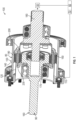
FIG. 1 shows a drive according to an embodiment having multiple input shafts and one output shaft; -
FIG. 2 shows flex splines and a circular gear of the drive; -
FIG. 3 shows the drive configured so that one of the input shafts is stationary and the other is rotating; -
FIG. 4 shows the drive configured so that another one of the input shafts is stationary and the other is rotating; -
FIG. 5 shows the drive configured so that both of the input shafts are rotating; -
FIG. 6 shows additional features of the flex splines and the circular gear of the drive; and -
FIG. 7 shows additional features of the drive. - A detailed description of one or more embodiments of the disclosed apparatus and method are presented herein by way of exemplification and not limitation with reference to the Figures.
- Turning to
FIG. 1 , aharmonic drive 100 is disclosed. As will be disclosed in greater detail below, thedrive 100 is configuration with a strain wave gear differential with an invertedstrain wave generator 140 and a conventionalstrain wave generator 170 as input to a shared opposed splinedcircular gear 230. That is, thedrive 100 is a harmonic drive that connects acontrol surface 50 of anaircraft 60, such a flap, to astationary structure 70 of theaircraft 60 such as frame member. As indicated below, thedrive 100 has redundant motive inputs, i.e., first and second input shafts, 130, 160 for a single output, i.e., anoutput shaft 180. Each of theinput shafts second motors motors control surface 50 can be operated as required, e.g., during flight. - The
drive 100 includes aground ring 110 that connects to thestationary structure 70. Afirst flex spline 120 extends axially from (e.g., is coupled to) theground ring 110. Thefirst input shaft 130 is radially exterior to thefirst flex spline 120. Thefirst input shaft 130 includes afirst wave generator 140 that engages thefirst flex spline 120. Asecond flex spline 150 is radially within (interior to) thefirst flex spline 120 and rotationally coupled to thefirst flex spline 120. Thesecond input shaft 160 is radially within thesecond flex spline 120. Thesecond input shaft 160 includes asecond wave generator 170 that engages thesecond flex spline 150. - The
output shaft 180 is coupled to thesecond flex spline 150. The first andsecond input shafts output shaft 180 is configured to rotate with rotation of either or both of the first andsecond input shafts second input shafts output shaft 180 is configured to counter-rotate relative to thefirst input shaft 130 and co-rotate relative to thesecond input shaft 160. - A first wave generator bearing 190 is between the
first wave generator 140 and thefirst flex spline 120. A second wave generator bearing 200 is between thesecond wave generator 170 and thesecond flex spline 150. - Turning to
FIG. 2 , thefirst flex spline 120 includes afirst spline 210 that faces radially inward. Thesecond flex spline 150 includes asecond spline 220 that faces radially outward. Thecircular gear 230 includes athird spline 240 that faces radially outward and engage thefirst spline 210. Thecircular gear 230 includes afourth spline 250 that faces radially inward and engages thesecond spline 220. - As can be appreciated, the splines 210-250 are axially aligned with each other and has a same axial span as each other. The
first spline 210 of thefirst flex spline 120 defines a first inverted tooth set (IT1). Thesecond flex spline 150 of thesecond flex spline 150 defines a first conventional tooth set (CT1). Thethird spline 240 of thecircular gear 230 defines a second inverted tooth set (IT2) that meshes with the first inverted tooth set (IT1). Thefourth spline 250 of thecircular gear 230 defines a second conventional tooth set (CT2) that meshes with the first conventional tooth set (CT1). IT1 and IT2 differ from each other and CT1 and CT2 differ from each other. - As shown in
FIG. 3 , when thefirst input shaft 130 is stationary, e.g., via a motor brake, and thesecond input shaft 160 rotates at a speed SI2, a first output speed SO1 of theoutput shaft 180 is proportional to the speed SI2 of thesecond input shaft 160 multiplied by a drive conventional gear ratio (DCGR), which is defined by:
- As shown in
FIG. 4 , when thefirst input shaft 130 rotates at a speed SI1, and thesecond input shaft 160 is stationary, e.g., via a motor brake, a second output speed SO2 of theoutput shaft 180 is proportional to a speed SI1 of thefirst input shaft 130 multiplied by a drive inverted gear ratio DIGR, which is defined by:
- As shown in
FIG. 5 , when the first andsecond input shafts output shaft 180 is proportional to a speed summed differential SSD. The speed summed differential SSD is proportional to a difference between SI2 multiplied by DCGR and SI1 multiplied by DIGR. This accounts for a difference between SO1 and SO2 that would result if the brakes were selectively engaged. - That is, in operation, as shown in
FIG. 4 , thefirst motor 80 would normally control operation of thefirst input shaft 130 to drive theoutput shaft 180 and obtain desired rotational position of thecontrol surface 50. However, if thefirst motor 80 were to entirely fail, the configuration ofFIG. 3 results is executed, such that operation of thesecond motor 90 drives thesecond input shaft 160 to provide for rotation of theoutput shaft 180. If thefirst motor 80 were to partially fail and either overspeed or under-speed, the configuration ofFIG. 5 is executed, with thesecond motor 90 driving thesecond input shaft 160 while thefirst motor 80 drives thefirst input shaft 130. - Turning to
FIG. 6 , thefirst flex spline 120 is a silk-hat shaped flex spline that extends from aforward end 120A to anaft end 120B. Theforward end 120A of thefirst flex spline 120 defines theground ring 110 and theaft end 120B of thefirst flex spline 120 defines thefirst spline 210. Thesecond flex spline 150 is a cup shaped flex spline that extends from aforward end 150A to anaft end 150B. Theforward end 150A of thesecond flex spline 150 defines the second spline and the aft end of thesecond flex spline 150 is aradial disk 260 that defines acenter aperture 270. Thecircular gear 230 extends from aforward end 230A to anaft end 230B. The third andfourth splines circular gear 230. - Turning to
FIG. 7 , thefirst input shaft 130 extends from aforward end 130A to anaft end 130B and has an outer surface 130C and aninner surface 130D. Theforward end 130A of thefirst input shaft 130 is axially adjacent to theground ring 110 and theaft end 130B of thefirst input shaft 130 is aft of theaft end 120B of thefirst flex spline 120 and theaft end 150B of thesecond flex spline 150. Theinner surface 130D of thefirst input shaft 130 includes an axiallyintermediate portion 130E that defines thefirst wave generator 140. - A forward outer bearing 270 is disposed against the outer surface 130C of the
first input shaft 130, at theforward end 130A of thefirst input shaft 130. An aftouter bearing 280 is disposed against the outer surface 130C of thefirst input shaft 130, at theaft end 130B of thefirst input shaft 130. - A ground ring diameter Dr defines an outer diameter of the
drive 100, and substantially matches an outer diameter defined by thebearings first input shaft 130 has a next larger diameter, being slightly smaller than the ground ring and its outer boundary defines abody 105 of thedrive 100 from which thesecond input shaft 160 and theoutput shaft 180 extend axially.Holes 111 in theground ring 110 receivefasteners 112 which may be bolts that mount thedrive 100 to a stationary structure. - The
second input shaft 160 extends from aforward end 160A to anaft end 160B and defines aforward portion 162, an aft portion 164 and anintermediate portion 166 therebetween. Theforward portion 162 of thesecond input shaft 160 extends from theforward end 160A of thesecond input shaft 160 to theground ring 110 and defines a solid shaft having a first forward diameter Df1. Theintermediate portion 166 of thesecond input shaft 160 has an intermediate diameter Di that is greater than the first forward diameter Df1. A forwardinner bearing 290 is located between theintermediate portion 166 of thesecond input shaft 160 and thefirst flex spline 120. - An axial span (length) of the aft portion 164 of the
second input shaft 160 is the same as theintermediate portion 130E of thefirst input shaft 130. The aft portion 164 of thesecond input shaft 160 is axially aligned with theintermediate portion 130E of thefirst input shaft 130. A first aft diameter Da1 is defined by the aft portion 164 of thesecond input shaft 160 that is greater than the intermediate diameter Di. Thesecond wave generator 170 is defined by the aft portion 164 of thesecond input shaft 160. - The
second input shaft 160 defines ablind hole 168 that extends forward from theaft end 160B of thesecond input shaft 160, along the aft portion 164 andintermediate portion 166 of thesecond input shaft 160. That is, theblind hole 168 defines aforward portion 168A and an aft portion 168B, where the aft portion 168B defines anaperture 168C of theblind hole 168. Theblind hole 168 has an aft hole diameter Dah along the aft portion 164 of thesecond input shaft 160, i.e., along its aft portion 168B. Theblind hole 168 has a forward hole diameter Dfh along theintermediate portion 166 of thesecond input shaft 160, i.e., along itsforward portion 168A, that is smaller than the aft hole diameter Dah. - The
output shaft 180 extends from aforward end 180A to anaft end 180B and defines aforward portion 182, anaft portion 184, andflange 186 between theforward portion 182 and theaft portion 184. Theflange 186 has a flange diameter Df and theflange 186 is connected to theradial disk 260 of thesecond flex spline 150, e.g., viafasteners 300 such as bolts. Theflange 186 has a flange thickness Tf so that anaft surface 186A of theflange 186 is axially aligned with theaft end 130B of thefirst input shaft 130. - The
aft portion 184 of theoutput shaft 180 has a second aft diameter Da2 that is smaller than the flange diameter Df. Theforward portion 180B of theoutput shaft 180 defines a connecting shaft that extends through thecenter aperture 270 in thesecond spline 220 and into theblind hole 168 in thesecond input shaft 160. Theforward portion 182 of theoutput shaft 180 has a second forward diameter Df2 that is smaller than the second aft diameter Da2. Thecenter aperture 270 in thesecond flex spline 150 is sized for receiving theforward portion 182 of theoutput shaft 180, to pass therethrough. - An aft
inner bearing 310 is disposed in theblind hole 168 of thesecond input shaft 160. The aftinner bearing 310 is located between theforward portion 182 of theoutput shaft 180 and the aft portion 164 of thesecond input shaft 160. An aft drive bearing 320 surrounds a portion of theaft portion 184 of theoutput shaft 180. The aft drive bearing 320 is located against theflange 186 of theoutput shaft 180. - A
forward clip 330 extends along a forward end ofcircular gear 230, thesecond flex spline 150, the second wave generator bearing 200 and the aft portion 164 of thesecond input shaft 160. Anaft clip 340 extends along an aft end of thecircular gear 230, thefirst flex spline 120, and the firstwave generator bearing 190. The clips maintain the axial alignment of the drive components. - Each of the bearings disclosed above may be a ball bearing.
- The disclosed
drive 100 provides redundant motive elements, i.e., input shafts, such that a combination of motive input provides a speed sum differential as the output. Thedrive 100 provides a high gear ratio to a small volume differential. The drive provides fault tolerance, i.e., if a motor connected to thefirst input shaft 130 fails entirely or partially, a second motor connected to thesecond input shaft 160 may engage so that an output can be manipulated as required. Thedrive 100 provides an integrated differential and gear reduction design that optimizes weight, volume, cost, and reliability. - The terminology used herein is for the purpose of describing particular embodiments only and is not intended to be limiting of the present disclosure. As used herein, the singular forms "a", "an" and "the" are intended to include the plural forms as well, unless the context clearly indicates otherwise. It will be further understood that the terms "comprises" and/or "comprising," when used in this specification, specify the presence of stated features, integers, steps, operations, elements, and/or components, but do not preclude the presence or addition of one or more other features, integers, steps, operations, element components, and/or groups thereof.
- Those of skill in the art will appreciate that various example embodiments are shown and described herein, each having certain features in the particular embodiments, but the present invention may include variations that fall within the scope of the invention as defined by the claims.
Claims (15)
- A harmonic drive, comprising:a ground ring (110);a first flex spline (120) extending axially from the ground ring;a first input shaft (SI1) that is radially exterior to the first flex spline,wherein the first input shaft includes a first wave generator (140) that engages the first flex spline;a second flex spline (150), radially within the first flex spline and rotationally coupled to the first flex spline,a second input shaft (SI2) that is radially within the second flex spline,wherein the second input shaft includes a second wave generator (170) that engages the second flex spline;an output shaft (SO) coupled to the second flex spline,wherein:the first flex spline includes a first spline (210) that faces radially inward;the second flex spline includes a second spline (220) that faces radially outward; andthe drive further includes a circular gear (230) that includes: a third spline (240) that face outwardly and engages the first spline; and a fourth spline (250) that faces radially inward and engages the second spline.
- The drive of claim 1, whereinthe first and second input shafts are configured to counter-rotate relative to each other, and optionally whereinthe output shaft is configured to counter-rotate relative to the first input shaft and co-rotate relative to the second input shaft.
- The drive of claim 1 or 2, including:a first wave generator bearing (190) between the first wave generator and the first flex spline; anda second wave generator bearing (200) between the second wave generator and the second flex spline.
- The drive of any preceding claim, wherein:
the first and second input shafts are configured to rotate separately or simultaneously, and the output shaft is configured to rotate with rotation of either or both of the first and second input shafts. - The drive of any preceding claim, wherein
the splines are axially aligned with each other. - The drive of any preceding claim, whereinthe first spline (210) of the first flex spline (120) defines a first inverted tooth set (IT1);the second spline (220) of the second flex spline (150) defines a first conventional tooth set (CT1); andthe third spline (240) of the circular gear (230) defines a second inverted tooth set (IT2) that mesh with the first inverted tooth set (IT1); andthe fourth spline (250) of the circular gear (230) defines a second conventional tooth set (CT2) that mesh with the first conventional tooth set (CT1).
- The drive of claim 6, wherein
when the first input shaft is stationary and the second input shaft rotates, a first output speed (SO1) of the output shaft (SO) is proportional to a speed of the first input shaft (SI1) multiplied by a drive conventional gear ratio, DCGR, of
- The drive of claim 7, whereinwhen the first input shaft rotates and the second input shaft is stationary, the second output speed (S02) of the output shaft (SO) is proportional to a drive inverted gear ratio (DIGR) of:

whereinwhen the first and second input shafts rotate, a third output speed (SO3) of the output shaft is proportional to a speed summed differential, which is proportional to a differential between SI2 multiplied by DCGR and SI1 multiplied by DIGR. - The drive of any preceding claim, whereinthe first flex spline is a silk-hat shaped flex spline that extends from a forward end to an aft end, andwherein the forward end of the first flex spline defines the ground ring and the aft end of the first flex spline defines the first spline.
- The drive of claim 9, whereinthe second flex spline is a cup shaped flex spline that extends from a forward end to an aft end, andwherein the forward end of the second flex spline defines the second spline and the aft end of the second flex spline is a radial disk that defines a center aperture.
- The drive of claim 10, wherein:the first input shaft extends from a forward end to an aft end and has an inner surface and an outer surface;the forward end of the first input shaft is axially adjacent to the ground ring and the aft end of the first input shaft is aft of the aft end of the first flex spline and the second flex spline; andthe inner surface of the first input shaft includes an axially intermediate portion that defines the first wave generator, and optionally further including:a forward outer bearing (270) disposed against the outer surface of the first input shaft, at the forward end of the first input shaft; andan aft outer bearing (280) against the outer surface of the first input shaft, at the aft end of the first input shaft.
- The drive of claim 11, wherein:the second input shaft extends from a forward end to an aft end and defines a forward portion, an aft portion and an intermediate portion;the forward portion of the second input shaft extends from the forward end of the second input shaft to the ground ring and defines a solid shaft having a first forward diameter;the intermediate portion of the second input shaft has an intermediate diameter that is greater than the first forward diameter; andthe aft portion of the second input shaft has an axial span that is the same as the intermediate portion of the first input shaft and is axially aligned with the intermediate portion of the first input shaft, andwherein the aft portion of the second input shaft has a first aft diameter that is greater than the intermediate diameter, and wherein the aft portion of the second input shaft defines the second wave generator; and optionally further comprisinga forward inner bearing (290) located between the intermediate portion of the second input shaft and the first flex spline.
- The drive of claim 12, wherein:the second input shaft defines a blind hole (168) that extends forward from the aft end of the second input shaft, along the aft portion and the intermediate portion of the second input shaft; andthe blind hole has an aft hole diameter along the aft portion of the second input shaft and a forward hole diameter along the intermediate portion of the second input shaft that is smaller than the aft hole diameter.
- The drive of claim 13, wherein:the output shaft extends from a forward end to an aft end and defines a forward portion, an aft portion, and flange between the forward portion and the aft portion;the flange has a flange diameter and the flange is connected to the radial disk of the second flex spline, wherein the flange has a flange thickness so that an aft surface of the flange is axially aligned with the aft end of the first input shaft;the aft portion of the output shaft has a second aft diameter that is smaller than the flange diameter; andthe forward portion of the output shaft defines a connecting shaft that extends through the center aperture in the second flex spline, into the blind hole in the second input shaft,wherein the forward portion of the output shaft has a second forward diameter that is smaller than the second aft diameter, andthe center aperture in the second flex spline is sized for receiving the forward portion of the output shaft; and optionally:further includingan aft inner bearing disposed in the blind hole of the second input shaft, between the forward portion of the output shaft and the aft portion of the second input shaft.
- The drive of claim 14, including
an aft drive bearing surrounding a portion of the aft portion of the output shaft, wherein the aft drive bearing is located against the portion of the output shaft.
Applications Claiming Priority (1)
| Application Number | Priority Date | Filing Date | Title |
|---|---|---|---|
| US18/390,332 US12215770B1 (en) | 2023-12-20 | 2023-12-20 | Strain wave gear differential with high gear reduction |
Publications (1)
| Publication Number | Publication Date |
|---|---|
| EP4575267A1 true EP4575267A1 (en) | 2025-06-25 |
Family
ID=93926770
Family Applications (1)
| Application Number | Title | Priority Date | Filing Date |
|---|---|---|---|
| EP24222296.6A Pending EP4575267A1 (en) | 2023-12-20 | 2024-12-20 | Strain wave gear differential with high gear reduction |
Country Status (2)
| Country | Link |
|---|---|
| US (1) | US12215770B1 (en) |
| EP (1) | EP4575267A1 (en) |
Citations (4)
| Publication number | Priority date | Publication date | Assignee | Title |
|---|---|---|---|---|
| US6029543A (en) * | 1999-02-01 | 2000-02-29 | Harmonic Drive Technologies | Piezo-electric drive arrangement for a harmonic drive transmission |
| CN113339478A (en) * | 2021-06-15 | 2021-09-03 | 苏州兴域机器人装备有限责任公司 | Radial double-wave flexible transmission speed reducer |
| CN115789181A (en) * | 2022-12-07 | 2023-03-14 | 德镁精密传动(深圳)有限公司 | Harmonic reducer |
| US20230202649A1 (en) * | 2020-04-17 | 2023-06-29 | Airbus Helicopters Technik Gmbh | Actuator for aviation applications |
Family Cites Families (8)
| Publication number | Priority date | Publication date | Assignee | Title |
|---|---|---|---|---|
| JP3336603B2 (en) | 1996-11-05 | 2002-10-21 | トヨタ自動車株式会社 | Power steering device |
| US6155220A (en) | 1999-09-13 | 2000-12-05 | General Motors Corporation | Piezoelectric differential cam phaser |
| JP2001112215A (en) | 1999-10-05 | 2001-04-20 | Yaskawa Electric Corp | Reducer integrated actuator |
| US9157517B2 (en) * | 2013-09-16 | 2015-10-13 | Hamilton Sundstrand Corporation | Compound harmonic drive |
| US9528587B2 (en) * | 2014-07-08 | 2016-12-27 | Hamilton Sundstrand Corporation | Harmonic drive and method of assembling |
| US10030756B2 (en) * | 2016-06-02 | 2018-07-24 | Honeywell International Inc. | Automatic flight control actuator systems |
| US10584782B2 (en) * | 2016-08-05 | 2020-03-10 | Hamilton Sundstrand Corporation | Joined flex spline for compound harmonic drive |
| CN112855865B (en) | 2020-12-30 | 2022-05-24 | 苏州绿科智能机器人研究院有限公司 | Composite speed reducer for industrial application |
-
2023
- 2023-12-20 US US18/390,332 patent/US12215770B1/en active Active
-
2024
- 2024-12-20 EP EP24222296.6A patent/EP4575267A1/en active Pending
Patent Citations (4)
| Publication number | Priority date | Publication date | Assignee | Title |
|---|---|---|---|---|
| US6029543A (en) * | 1999-02-01 | 2000-02-29 | Harmonic Drive Technologies | Piezo-electric drive arrangement for a harmonic drive transmission |
| US20230202649A1 (en) * | 2020-04-17 | 2023-06-29 | Airbus Helicopters Technik Gmbh | Actuator for aviation applications |
| CN113339478A (en) * | 2021-06-15 | 2021-09-03 | 苏州兴域机器人装备有限责任公司 | Radial double-wave flexible transmission speed reducer |
| CN115789181A (en) * | 2022-12-07 | 2023-03-14 | 德镁精密传动(深圳)有限公司 | Harmonic reducer |
Also Published As
| Publication number | Publication date |
|---|---|
| US12215770B1 (en) | 2025-02-04 |
Similar Documents
| Publication | Publication Date | Title |
|---|---|---|
| US5178028A (en) | Offset face gear transmission | |
| US5807202A (en) | Differential speed transmission | |
| US9115650B2 (en) | Ring gear mounting arrangement with oil scavenge scheme | |
| CN103097243B (en) | Be particularly useful for propelling and the Movement transmit assembly of autogiro | |
| US6612195B2 (en) | Split-torque face gear transmission | |
| JP3538958B2 (en) | Drive for electric vehicles | |
| CN109923335B (en) | Planet carrier for reduction unit with planetary gear train | |
| CN109219695B (en) | Aircraft turbine engine with planetary or epicyclic reduction gears | |
| US20050011307A1 (en) | Split-torque gear box | |
| US8172530B2 (en) | Pitch change actuation system for a counter-rotating propeller | |
| EP3933228B1 (en) | Sealed coaxial input and output shafts | |
| US8870538B2 (en) | Counter rotating facegear gearbox | |
| US10495005B2 (en) | Epicyclic reduction device for the rotational drive of blade sets of a reduction turbomachine | |
| JP2007113580A (en) | Counter-rotating fan assembly and gas turbine engine assembly including counter-rotating fan assembly | |
| EP3279512B1 (en) | Joined flex spline for compound harmonic drive | |
| US4983153A (en) | Gear unit, particularly for use in a helicopter | |
| EP1781525B1 (en) | Electric drive transmission | |
| KR20210118386A (en) | hover-capable aircraft | |
| US20170073066A1 (en) | Power transmission system and an aircraft having a rotary wing | |
| EP3193040A1 (en) | Planetary gear assembly | |
| EP3561263B1 (en) | Gear assembly for coaxial shafts in gas turbine engine | |
| US12215770B1 (en) | Strain wave gear differential with high gear reduction | |
| EP1295788B1 (en) | Hybrid power input quill for transmissions | |
| US11498670B2 (en) | Coaxial split torque gear box | |
| US20040214682A1 (en) | Dual stage differential speed transmission |
Legal Events
| Date | Code | Title | Description |
|---|---|---|---|
| PUAI | Public reference made under article 153(3) epc to a published international application that has entered the european phase |
Free format text: ORIGINAL CODE: 0009012 |
|
| STAA | Information on the status of an ep patent application or granted ep patent |
Free format text: STATUS: THE APPLICATION HAS BEEN PUBLISHED |
|
| AK | Designated contracting states |
Kind code of ref document: A1 Designated state(s): AL AT BE BG CH CY CZ DE DK EE ES FI FR GB GR HR HU IE IS IT LI LT LU LV MC ME MK MT NL NO PL PT RO RS SE SI SK SM TR |
|
| STAA | Information on the status of an ep patent application or granted ep patent |
Free format text: STATUS: REQUEST FOR EXAMINATION WAS MADE |
|
| 17P | Request for examination filed |
Effective date: 20251128 |