EP4575266A1 - System for an actuator - Google Patents
System for an actuator Download PDFInfo
- Publication number
- EP4575266A1 EP4575266A1 EP23307311.3A EP23307311A EP4575266A1 EP 4575266 A1 EP4575266 A1 EP 4575266A1 EP 23307311 A EP23307311 A EP 23307311A EP 4575266 A1 EP4575266 A1 EP 4575266A1
- Authority
- EP
- European Patent Office
- Prior art keywords
- actuator
- load path
- nut
- primary
- screw shaft
- Prior art date
- Legal status (The legal status is an assumption and is not a legal conclusion. Google has not performed a legal analysis and makes no representation as to the accuracy of the status listed.)
- Pending
Links
Images







Classifications
-
- F—MECHANICAL ENGINEERING; LIGHTING; HEATING; WEAPONS; BLASTING
- F16—ENGINEERING ELEMENTS AND UNITS; GENERAL MEASURES FOR PRODUCING AND MAINTAINING EFFECTIVE FUNCTIONING OF MACHINES OR INSTALLATIONS; THERMAL INSULATION IN GENERAL
- F16H—GEARING
- F16H25/00—Gearings comprising primarily only cams, cam-followers and screw-and-nut mechanisms
- F16H25/18—Gearings comprising primarily only cams, cam-followers and screw-and-nut mechanisms for conveying or interconverting oscillating or reciprocating motions
- F16H25/20—Screw mechanisms
- F16H25/205—Screw mechanisms comprising alternate power paths, e.g. for fail safe back-up
-
- B—PERFORMING OPERATIONS; TRANSPORTING
- B64—AIRCRAFT; AVIATION; COSMONAUTICS
- B64C—AEROPLANES; HELICOPTERS
- B64C13/00—Control systems or transmitting systems for actuating flying-control surfaces, lift-increasing flaps, air brakes, or spoilers
- B64C13/24—Transmitting means
- B64C13/26—Transmitting means without power amplification or where power amplification is irrelevant
- B64C13/28—Transmitting means without power amplification or where power amplification is irrelevant mechanical
-
- B—PERFORMING OPERATIONS; TRANSPORTING
- B64—AIRCRAFT; AVIATION; COSMONAUTICS
- B64F—GROUND OR AIRCRAFT-CARRIER-DECK INSTALLATIONS SPECIALLY ADAPTED FOR USE IN CONNECTION WITH AIRCRAFT; DESIGNING, MANUFACTURING, ASSEMBLING, CLEANING, MAINTAINING OR REPAIRING AIRCRAFT, NOT OTHERWISE PROVIDED FOR; HANDLING, TRANSPORTING, TESTING OR INSPECTING AIRCRAFT COMPONENTS, NOT OTHERWISE PROVIDED FOR
- B64F5/00—Designing, manufacturing, assembling, cleaning, maintaining or repairing aircraft, not otherwise provided for; Handling, transporting, testing or inspecting aircraft components, not otherwise provided for
- B64F5/60—Testing or inspecting aircraft components or systems
-
- F—MECHANICAL ENGINEERING; LIGHTING; HEATING; WEAPONS; BLASTING
- F16—ENGINEERING ELEMENTS AND UNITS; GENERAL MEASURES FOR PRODUCING AND MAINTAINING EFFECTIVE FUNCTIONING OF MACHINES OR INSTALLATIONS; THERMAL INSULATION IN GENERAL
- F16H—GEARING
- F16H25/00—Gearings comprising primarily only cams, cam-followers and screw-and-nut mechanisms
- F16H25/18—Gearings comprising primarily only cams, cam-followers and screw-and-nut mechanisms for conveying or interconverting oscillating or reciprocating motions
- F16H25/20—Screw mechanisms
- F16H25/2021—Screw mechanisms with means for avoiding overloading
-
- G—PHYSICS
- G01—MEASURING; TESTING
- G01B—MEASURING LENGTH, THICKNESS OR SIMILAR LINEAR DIMENSIONS; MEASURING ANGLES; MEASURING AREAS; MEASURING IRREGULARITIES OF SURFACES OR CONTOURS
- G01B7/00—Measuring arrangements characterised by the use of electric or magnetic techniques
- G01B7/16—Measuring arrangements characterised by the use of electric or magnetic techniques for measuring the deformation in a solid, e.g. by resistance strain gauge
-
- B—PERFORMING OPERATIONS; TRANSPORTING
- B64—AIRCRAFT; AVIATION; COSMONAUTICS
- B64D—EQUIPMENT FOR FITTING IN OR TO AIRCRAFT; FLIGHT SUITS; PARACHUTES; ARRANGEMENT OR MOUNTING OF POWER PLANTS OR PROPULSION TRANSMISSIONS IN AIRCRAFT
- B64D45/00—Aircraft indicators or protectors not otherwise provided for
- B64D2045/0085—Devices for aircraft health monitoring, e.g. monitoring flutter or vibration
-
- G—PHYSICS
- G01—MEASURING; TESTING
- G01M—TESTING STATIC OR DYNAMIC BALANCE OF MACHINES OR STRUCTURES; TESTING OF STRUCTURES OR APPARATUS, NOT OTHERWISE PROVIDED FOR
- G01M13/00—Testing of machine parts
- G01M13/02—Gearings; Transmission mechanisms
- G01M13/028—Acoustic or vibration analysis
-
- G—PHYSICS
- G01—MEASURING; TESTING
- G01M—TESTING STATIC OR DYNAMIC BALANCE OF MACHINES OR STRUCTURES; TESTING OF STRUCTURES OR APPARATUS, NOT OTHERWISE PROVIDED FOR
- G01M5/00—Investigating the elasticity of structures, e.g. deflection of bridges or air-craft wings
- G01M5/0033—Investigating the elasticity of structures, e.g. deflection of bridges or air-craft wings by determining damage, crack or wear
Definitions
- the present disclosure relates to a system for identifying a failure of the primary load path in an actuator and to an actuator including such a system, for example a trimmable horizontal stabiliser actuator ("THSA") for an aircraft, wherein the actuator includes a primary load path and a secondary load path that is configured to carry the load of the actuator upon failure of the primary load path.
- THSA trimmable horizontal stabiliser actuator
- Actuators typically provide a structural link between stationary parts of the actuator (and the object to which the actuator is attached), which provide a driving force for the actuator, and the moving parts of the actuator that actuate a component. Various loads are transmitted from the component to the stationary parts of the actuator via the moving parts thereof. Most actuators provide this structural link in the form of a load path, along which various tolerances are provided between components to account for excessive loading in use.
- THSA trimmable horizontal stabiliser actuator
- an actuator for an aircraft, which is submitted to various aerodynamic loads in use (e.g., flutter caused by turbulence).
- THSA trimmable horizontal stabiliser actuator
- such actuators comprise a primary load path that is configured to support aerodynamic loads in normal condition, and a secondary load path that is configured to support aerodynamic loads upon failure of the primary load path. During normal use, the secondary load path is intended to remain in an unloaded condition.
- a system for identifying a failure of the primary load path in an actuator comprising a screw shaft and a nut assembly moveable along the screw shaft.
- the nut assembly comprises a primary nut for transmitting load through the actuator along a primary load path, and a secondary nut for transmitting load through the actuator along a secondary load path.
- the nut assembly is configured such that, in normal operation, the secondary nut is not engaged with the screw shaft and load is transmitted through the actuator along the primary load path, and such that, upon failure of the primary load path, the secondary nut is configured to engage the screw shaft and transmit load through the actuator along the secondary load path.
- the system comprises a strain gauge configured to be mounted to the actuator and to measure vibrations of the actuator, and a processor configured to identify a failure of the primary load path from the measured vibrations.
- the strain gauge is a piezoelectric strain gauge.
- the strain gauge may be mounted on a support member configured to be mounted to the actuator.
- the strain gauge and the processor may be connected with a wired connection. In any example of the disclosure, the strain gauge and the processor may be connected wirelessly.
- an actuator comprising a screw shaft and a nut assembly moveable along the screw shaft.
- the nut assembly comprises a primary nut for transmitting load through the actuator along a primary load path, and a secondary nut for transmitting load through the actuator along a secondary load path.
- the nut assembly is configured such that, in normal operation, the secondary nut is not engaged with the screw shaft and load is transmitted through the actuator along the primary load path, and such that, upon failure of the primary load path, the secondary nut is configured to engage the screw shaft and transmit load through the actuator along the secondary load path.
- the actuator comprises a system of any of the above examples.
- the strain gauge or the support member is mounted to the actuator.
- the strain gauge or the support member may be mounted on the nut assembly.
- the secondary nut may comprise a pair of trunnions.
- the nut assembly may comprise a pair of junction plates.
- each of the junction plates may comprise an opening for receiving a respective trunnion of the pair of trunnions.
- the trunnions in normal operation, may not contact respective openings in the junction plate.
- a system for identifying a failure of the primary load path in an actuator comprising a screw shaft and a nut assembly moveable along the screw shaft.
- the nut assembly comprises a primary nut for transmitting load through the actuator along a primary load path, and a secondary nut for transmitting load through the actuator along a secondary load path.
- the nut assembly is configured such that, in normal operation, the secondary nut is not engaged with the screw shaft and load is transmitted through the actuator along the primary load path, and such that, upon failure of the primary load path, the secondary nut is configured to engage the screw shaft and transmit load through the actuator along the secondary load path.
- the system comprises a support member configured to be mounted to the nut assembly, wherein, upon failure of the primary load path, the support member is configured to be impacted by the secondary nut and to vibrate due to the impact.
- the system comprises a strain gauge mounted to the support member and configured to measure vibrations of the support member, and a processor configured to identify a failure of the primary load path from the measured vibrations.
- the support member may comprise an impact portion configured such that, upon failure of the primary load path, the impact portion is impacted by a component of the secondary nut before or simultaneously with the loading of the secondary load path.
- the strain gauge may be mounted on the impact portion.
- the strain gauge may be one of a piezoelectric strain gauge, a piezoresistive strain gauge, a capacitive strain gauge or a metal foil strain gauge.
- the processor may be mounted on the support member.
- the impact portion may be a protrusion.
- the strain gauge may be attached and /or mounted directly to the support member.
- the strain gauge may be attached anywhere on the support member.
- the strain gauge may be attached on the support member on a surface facing away from the nut assembly.
- an actuator comprising a screw shaft and a nut assembly moveable along the screw shaft.
- the nut assembly comprises a primary nut for transmitting load through the actuator along a primary load path, and a secondary nut for transmitting load through the actuator along a secondary load path.
- the nut assembly is configured such that, in normal operation, the secondary nut is not engaged with the screw shaft and load is transmitted through the actuator along the primary load path, and such that, upon failure of the primary load path, the secondary nut is configured to engage the screw shaft and transmit load through the actuator along the secondary load path.
- the actuator comprises the system of any of the above examples, wherein the support member is mounted to the nut assembly.
- the nut assembly may comprise a junction plate configured to form a portion of the primary load path in normal operation, and further configured to form a portion of the secondary load path upon failure of the primary load path.
- the strain gauge or the support member may be mounted on the junction plate.
- the secondary nut may comprise an outwardly extending member, and the support member may be configured to be impacted by the outwardly extending member.
- the outwardly extending member is a pin.
- the secondary nut comprises a pair of trunnions, and the outwardly extending member is one of the trunnions.
- the outwardly extending member extends through an opening in the junction plate.
- the processor may be configured to compare the measured vibrations to a predetermined threshold value to identify the failure of the primary load path.
- the system may comprise a housing configured to protect the strain gauge.
- the actuator may be a linear actuator.
- the actuator may be an electromechanical linear actuator.
- the actuator may be a trimmable horizontal stabiliser actuator.
- the actuator may comprise a static portion configured to be attached to a fixed structure, and the nut assembly may be moveable relative to the static portion.
- an aircraft comprising a system or an actuator of any of the above examples.
- a method for identifying a failure of the primary load path in an actuator comprises a screw shaft and a nut assembly moveable along the screw shaft.
- the nut assembly comprises a primary nut for transmitting load through the actuator along a primary load path, and a secondary nut for transmitting load through the actuator along a secondary load path.
- the nut assembly is configured such that, in normal operation, the secondary nut is not engaged with the screw shaft and load is transmitted through the actuator along the primary load path, and such that, upon failure of the primary load path, the secondary nut is configured to engage the screw shaft and transmit load through the actuator along the secondary load path.
- the method comprises measuring vibrations of the actuator by a piezoelectric strain gauge mounted to the actuator, and processing the measured vibrations to identify a failure of the primary load path.
- the actuator comprises a screw shaft and a nut assembly moveable along the screw shaft.
- the nut assembly comprises a primary nut for transmitting load through the actuator along a primary load path, and a secondary nut for transmitting load through the actuator along a secondary load path.
- the nut assembly is configured such that, in normal operation, the secondary nut is not engaged with the screw shaft and load is transmitted through the actuator along the primary load path, and such that, upon failure of the primary load path, the secondary nut is configured to engage the screw shaft and transmit load through the actuator along the secondary load path.
- the method comprises: mounting a support member to the nut assembly, wherein, upon failure of the primary load path, the support member is configured to be impacted by the secondary nut and to vibrate due to the impact; measuring vibrations of the support member by a strain gauge mounted to the support member, and processing the measured vibrations to identify a failure of the primary load path.
- the processing the measured vibrations may comprise comparing the measured vibrations to a pre-determined threshold value, and identifying a failure of the primary load path when the measured vibrations exceed the predetermined threshold value.
- the method may comprise notifying a user and / or activating an alarm if primary load path failure is determined.
- the actuator comprises a screw shaft and a nut assembly moveable along the screw shaft.
- the nut assembly comprises a primary nut for transmitting load through the actuator along a primary load path, and a secondary nut for transmitting load through the actuator along a secondary load path.
- the nut assembly is configured such that, in normal operation, the secondary nut is not engaged with the screw shaft and load is transmitted through the actuator along the primary load path, and such that, upon failure of the primary load path, the secondary nut is configured to engage the screw shaft and transmit load through the actuator along the secondary load path.
- the method comprises installing a system of any of the above examples on the actuator.
- the actuator comprises a fastener
- the step of installing the system of any of the above examples on the actuator comprises removing the fastener, positioning the system on the actuator, and replacing the fastener so as to secure the system to the actuator.
- the present disclosure relates to actuators, such as for example a flight control actuator, such as a trimmable horizontal stabiliser actuator ("THSA") for an aircraft.
- the actuator includes a primary load path and a secondary load path that is configured to carry the load of the actuator upon failure of the primary load path.
- the actuator includes a strain gauge and is configured to identify failure of the primary load path based on vibrations recorded by the strain gauge.
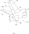
- Fig. 1 shows a schematic perspective view of the tail end 100 of an aircraft (not shown).
- the aircraft includes a vertical stabiliser 120 extending upwardly from the aircraft fuselage 110 and respective horizontal stabilisers 130a, 130b extending outwardly from the aircraft fuselage 110 on respective sides of the aircraft.
- One or more rudders 122 are provided at the trailing edge 124 (i.e. the rear face) of the vertical stabiliser 120 and one or more elevators 132 are provided on the trailing edge 134 (i.e. the rear face) of each horizontal stabiliser 130a, 130b.
- the vertical stabilisers 120, horizontal stabilisers 130a, 130b, rudders 122 and elevators 132 are adapted to be moved by actuation systems (not shown) to control movement of the aircraft.
- the actuation system typically includes a control system (not shown) and a number of actuators (not shown in Fig. 1 ) configured to move the respective vertical stabilisers 120, horizontal stabilisers 130a, 130b, rudders 122 and elevators 132 under the control of the control system.
- the actuators may take a number of different forms depending for example on the type and size of aircraft in which they are used.
- one or more electromechanical actuators more specifically electromechanical linear actuators may be provided in the actuation system.
- An example of an electromechanical linear actuator which may be used to move one of the horizontal stabilisers 130a, 130b is a "trimmable horizontal stabiliser actuator" (often referred to as a THSA).
- the electromechanical linear actuator according to various examples of the disclosure may for example be a THSA for use with horizontal stabilisers as described above. It will be understood however that the present disclosure is relevant to other types of electromechanical linear actuators and is not limited to actuators for use in aircraft or to THSAs.
- Fig. 2 shows an example actuator 200, which may be a flight control actuator, such as a trimmable horizontal stabiliser actuator ("THSA"), as described above.
- the actuator 200 may include a primary load path with a screw shaft 210 (e.g., that is hollow) connected at an end thereof, for example at its upper end as shown, to the aircraft via a static portion 202 including a first joint system 340 (e.g., a Carden joint system) joining with first aircraft structural elements S1.
- THSA trimmable horizontal stabiliser actuator
- the primary load path further includes a nut assembly 400 mounted on the screw shaft 210, and the nut assembly 400 is connected to a moveable component, for example, a stabiliser 130a, 130b of the aircraft, this connection being achieved for example by a second joint system 136 (e.g., a further Carden joint system).
- Nut assembly 400 is described in more detail below with respect to Figs. 5 and 6 .
- the secondary load path may be provided by means of a tie bar 390 that is within the screw shaft 210.
- the tie bar 390 is terminated at a first end by a male portion, in this case optionally taking the form of a spherical head 370, which is mounted within a female portion on a fastening piece 380, optionally taking the form of a recess 310.
- the fastening piece 380 may be connected to the structure of the aircraft via second aircraft structural elements S2.
- the actuator may also include some means for preventing motion of the nut assembly 400 relative to the screw shaft 210 and/or for fixing the stabiliser 130a/second joint system 136 in place when the primary load path fails.
- the nut assembly 400 also includes secondary load path elements that are enabled for use upon failure of the primary load path.
- the stabiliser 130a can either be safely held in a single position (in the case where the nut assembly 400 locks in place) or in some arrangements it might be permitted to continue normal movement should the tie bar 390 be connected with the screw shaft 210 in such a way as to permit continued rotation of the screw shaft 210 even after failure preventing it from carrying axial loads.
- the loading for the actuator 200 is carried via the primary load path.
- the loading is transferred to the secondary load path.
- Fig. 3 shows one possible arrangement for the primary and secondary load paths of the actuator 200, in which a component (e.g., a horizontal stabiliser) 130a, 130b is connected by optional arms and bushings 212 to a primary nut 420 which connects it to the screw shaft 210.
- a component e.g., a horizontal stabiliser
- 130a, 130b is connected by optional arms and bushings 212 to a primary nut 420 which connects it to the screw shaft 210.
- the primary nut 420 may include primary trunnions 430a, 430b operatively connected to respective junction plates 41 0a, 410b ( Fig. 6 ), and the primary nut 420 may comprise a ballscrew assembly (not shown).
- the primary nut 420 forms part of the lower attachment 400 of the actuator 200 that is dedicated to the primary load path.
- a joint system 240 (such as a Cardan joint system) will typically include no back elements 242 along with the primary load path gimbal 244, which may be coupled to the aircraft structure 246.
- the loading for the actuator 200 is carried via the primary load path.
- the horizontal stabiliser 130a is connected by the (optional) stabiliser arms and bushings 212 to a secondary nut 440.
- the secondary nut 440 typically comprises a screw thread that is arranged to lock with the threads of the screw shaft 210, preventing movement of the horizontal stabiliser 130a when the secondary load path is engaged.
- the secondary nut 440 may comprise secondary trunnions 450a, 450b which may be operatively connected to junction plates 410a, 410b.
- the secondary nut 440 may comprise screw threads (not shown) which can be joined to the thread of the screw shaft 210 when the secondary load path is engaged.
- the load in the secondary load path may be transmitted via the screw shaft 210 along the tie bar rod 390 ( Fig. 2 ) and optionally through the male end of the tie bar rod 390, which in this example is a tie bar sphere 370, and to an upper secondary attachment 202.
- the secondary nut 440 forms part of the lower attachment 400 of the actuator 200 that is dedicated to the secondary load path.
- FIGs. 4a and 4b Examples of the primary and secondary load paths in an actuator according to the disclosure are shown in Figs. 4a and 4b .
- the primary load path is shown in Fig. 4a , which illustrates the actuator 200 operating under normal operation.
- the secondary load path is shown in Fig. 4b , which illustrates the actuator 200 operating after failure of the primary load path.
- Fig. 4a shows the actuator 200 comprising a static portion 202 that is configured to attach to a stationary object, for example an aircraft fuselage (not shown in Figs. 4a and 4b ) as described above.
- the actuator 200 further comprises a motor (not shown) or other driving means configured to rotate the screw shaft 210 about an axis A.
- the actuator 200 further comprises a nut assembly 400 as previously described that is configured to move axially along the screw shaft 210 upon rotation thereof.
- a component for example a horizontal stabiliser 130a, may be operatively connected to the nut assembly 400, such that movement of the nut assembly 400 along the axis A causes actuation of the component by the actuator 200.
- a stop 220 located at one end of the screw shaft 210 is also shown in Figs. 4a and 4b . The stop 220 prevents the nut assembly 400 from detaching from the screw shaft 210.
- the static component 202 may comprise a primary portion 202a and a secondary portion 202b, which may be connected to different parts of the stationary object or may be connected via different connections.
- the static component 202 may also be referred to as the upper attachment 202.
- the nut assembly 400 comprises a primary nut 420 and a secondary nut 440, both of which may cooperate with the screw shaft 210 in order to drive the nut assembly 400 upon rotation thereof. This is described in more detail below.
- load is transferred from the component to which the actuator 200 is attached to the primary nut 420, and then to the primary portion 202a of the static component 202 via the screw shaft 210.
- This is referred to herein as a primary load path and is indicated by the arrows A1.
- a secondary load path (indicated by the arrows A2 in Fig. 4b ) is provided that is configured to transmit load between the static component 202 and the component to which the actuator 200 is attached.
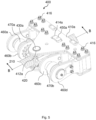
- Fig. 5 is a perspective view which shows the nut assembly 400 in more detail, and includes a portion of the screw shaft 210 for reference.
- Fig. 6 shows a cross-sectional side view of the nut assembly 400 of Fig. 5 taken along line B-B when the secondary load path is engaged as described further below.
- the nut assembly 400 comprises a primary nut 420.
- the primary nut 420 is mounted coaxially on the screw shaft 210.
- the primary nut 420 is part of a suitable ballscrew assembly (or similar means) and cooperates with the screw shaft 210.
- the ballscrew assembly comprises balls or ball bearings 422 arranged between the screw shaft 210 and the primary nut 420 so as to couple the screw shaft 210 and the primary nut 420 in the ballscrew assembly.
- the primary nut 420 comprises a pair of primary trunnions 430a, 430b.
- the primary nut 420 and primary trunnions 430a, 430b are shown as integrally formed.
- the primary nut 420 and primary trunnions 430a, 430b may be formed separately and secured together.
- the primary trunnions 430a, 430b can extend outwardly from the primary nut 420 in opposite directions to each other and / or from opposite sides of the primary nut 420.
- the primary trunnions 430a, 430b can be coaxial with each other.
- the primary trunnions 430a, 430b are shown as circular in cross-section. In other examples, the primary trunnions 430a, 430b may have any suitable cross-section, for example, square, rectangular or oval.
- the nut assembly 400 comprises a secondary nut 440.
- the secondary nut 440 is mounted coaxially with the screw shaft 210.
- the secondary nut 440 comprises a screw thread 441 for cooperating with the screw shaft 210.
- the secondary nut 440 comprises a pair of secondary trunnions 450a, 450b.
- the secondary trunnions 450a, 450b are shown as circular in cross-section. In other examples, the secondary trunnions 450a, 450b may have any suitable cross-section, for example, square, rectangular or oval.
- the secondary nut 440 does not transmit load under normal operation (i.e. when the primary load path is loaded).
- the nut assembly 400 may comprise bushings 432a, 432b which may be located on the respective primary trunnions 430a, 430b.
- the bushings 432a, 432b may be configured such that the primary trunnions 430a, 430b are snug within the openings 412a, 412b.
- one or more of the bushings 432a, 432b may comprise a flange 433a, 433b which abuts against a respective inner surface 434a, 434b of the junction plates 410a, 410b, so as to be retained in place.
- the nut assembly 400 comprises arm portions 460a, 460b, 460c, 460d that run axially along sides of the nut assembly 400 between the junction plates 410a, 410b.
- the arm portions 460a, 460b, 460c, 460d are arranged as pairs.
- a first pair of arm portions 460a, 460b are arranged on an opposite side of the screw shaft 210 to a second pair of arm portions 460c, 460d.
- Each pair of arm portions is configured to support respective connectors 470a, 470b.
- the primary nut 420, the secondary nut 440 and junction plates 410a, 410b are configured such that load is not transmitted to the secondary nut 440 during normal operation. In the example shown, this is achieved by providing a clearance around the secondary trunnions 450a, 450b such that the secondary trunnions 450a, 450b do not contact the inner edges defined by the openings 414a, 414b.
- this strain gauge is a piezoelectric strain gauge.
- the strain gauge can be a piezoresistive strain gauge, a capacitive strain gauge, a metal foil strain gauge or any other strain gauge configured to measure vibrations so that the system can detect this shock.
- the system may be used with a linear actuator, an electromechanical linear actuator or a trimmable horizontal stabiliser actuator.
- the piezoelectric strain gauge may be a piezoelectric omnidirectional strain sensor.
- One such piezoelectric omnidirectional strain sensor which may be used is a Dragonfly ® DGF-OMN-AA20206-10 Piezoelectric omnidirectional strain sensor manufactured by Wormsensing.
- the strain gauge may behave as a charge generator in parallel with a capacitor and a leakage resistor.
- the strain gauge may be passive and may not require any power supply.
- the strain gauge can be operated either in charge mode (using a charge amplifier) or voltage mode (direct measurement).
- the strain gauge of some examples is made from a thin piezoelectric ceramic.
- a sensing element of the strain gauge typically has a thickness of less than 10 ⁇ m. The thickness may be between 1 ⁇ m and 20 ⁇ m, or between 5 ⁇ m and 15 ⁇ m. These thicknesses enable the sensing element to have the flexibility and stretchability of a 2D material.
- the crystalline nature of the sensing element of some examples results in high durability and repeatability.
- ⁇ def is the unit of microstrain.
- Strain ( ⁇ ) is the ratio of change in length to the original length, therefore, microstrain is ⁇ ⁇ 10 -6 .
- a strain gauge of the type described above may enable measurements in the region of about 0.01 ⁇ def, having a sensitivity at least one hundred times greater than a typical metal foil strain gauge.
- Figs. 7a-c each show the nut assembly 400 shown in Fig. 5 with a piezoelectric strain gauge 480 attached thereto.
- the piezoelectric strain gauge 480 may be retrofitted to an existing actuator 200 as shown. That is, the actuator 200 requires no disassembly or only minor disassembly in order to attach the strain gauge 480 to the nut assembly 400.
- Fig. 8 shows a schematic side view of a system 600 for identifying a failure of the primary load path in an actuator, the system 600 including a piezoelectric strain gauge 480 such as that described above.
- the piezoelectric strain gauge 480 can be mounted on a plate 602 which in turn can be mounted to a part of the actuator 200, for example, the junction plate 410a.
- the plate 602 can be mounted to a part of the actuator 200 by a plurality of fixings 604 such as screws or rivets.
- a housing 606 may be provided, for example mounted on the plate 602 or integral therewith. The housing 606 may be configured to protect, for example to enclose, the piezoelectric strain gauge 480.
- the plate 602 and the housing 606 may be made of the same or different materials, including but not limited to metals.
- a wired connection 610 or a wireless connection may be provided between the piezoelectric strain gauge 480 and a processor or controller 608 which may be provided in the housing 606 as shown.
- a wired connection 612 or a wireless connection may be provided between the processor or controller 608 and the aircraft.
- the processor may be provided externally of the housing, for example in an aircraft.
- electronics for processing signals received from the piezoelectric strain gauge 480 may also be provided in the system 600 and within the housing 606.
- the piezoelectric strain gauge 480 is attached to an outer surface of a junction plate 410a.
- the piezoelectric strain gauge 480 may be located to be aligned with the secondary trunnion 450a in the axial direction.
- the piezoelectric strain gauge 480 may be offset such that it is not aligned with the secondary trunnion 450a.
- the piezoelectric strain gauge 480 is positioned such that the secondary trunnion 450a is located axially between the piezoelectric strain gauge 480 and the primary trunnion 430a.
- the piezoelectric strain gauge 480 is attached to an outer surface of junction plate 410a.
- the piezoelectric strain gauge 480 or in some examples the system 600 including the piezoelectric strain gauge 480, is located to be aligned with the secondary trunnion 450a in the axial direction.
- the piezoelectric strain gauge 480 may be offset such that it is not aligned with the secondary trunnion 450a.
- the piezoelectric strain gauge 480 is positioned such that the piezoelectric strain gauge 480 is located axially between the secondary trunnion 450a and the primary trunnion 430a.
- the piezoelectric strain gauge 480 is located axially closer to the secondary trunnion 450a than to the primary trunnion 430a. In other examples, the piezoelectric strain gauge 480 may be located equidistant between the primary trunnion 430a and secondary trunnion 450a. In other examples, the piezoelectric strain gauge 480 may be located closer to the primary trunnion 430a than to the secondary trunnion 450a.
- the piezoelectric strain gauge 480 is attached to an outer surface of junction plate 410a.
- the piezoelectric strain gauge 480 is located to be axially offset from the secondary trunnion 450a.
- the piezoelectric strain gauge 480 may be offset such that it is not aligned with the secondary trunnion 450a.
- the piezoelectric strain gauge 480 is positioned such that the secondary trunnion 450a is located axially between the piezoelectric strain gauge 480 and the primary trunnion 430a.
- the piezoelectric strain gauge 480 may be located anywhere on the junction plate 410a. In some examples, the piezoelectric strain gauge 480 may be attached to junction plate 410b.
- the piezoelectric strain gauge 480 may be attached to a part of the actuator 200, for example the junction plate 410a, 410b with an adhesive.
- the piezoelectric strain gauge 480 may be attached to the stop 220.
- a shock (or in other word a vibration) is generated when the junction plates 410a, 410b contact respective secondary trunnions 450a, 450b.
- the shock is detectable by the piezoelectric strain gauge 480.
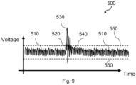
- Fig. 9 shows an example signal 500 taken from the piezoelectric strain gauge 480 when the piezoelectric strain gauge 480 is located on the junction plate 410a as shown in Figs. 7a and 7b .
- voltage is shown on the y-axis and is measured against time, shown on the x-axis.
- the strain gauge 480 may measure background vibrations 510 experienced by the actuator 200. It is to be understood that background vibrations are those vibrations which the actuator may experience under normal use. It is to be understood that in any example, signal or signal data may be referred to as measured vibrations.
- the background vibrations 510 may always be present during normal use, the background vibrations are measurable with the strain gauge 480.
- the background vibrations 510 have a regular and repetitive signature. It is to be understood that the background vibrations may be more or less regular and repetitive than shown in Fig. 9 .
- the measured voltage may vary more or less than shown dependent on where the strain gauge 480 is located on the junction plate 410a.
- the piezoelectric strain gauge 480 is configured such that, when in one of the positions shown, it is capable of measuring both the loading of the junction plates 410a, 410b by the respective secondary trunnions 450a, 450b and the shock generated therefrom, which has been referred to above as the loading of the secondary load path. It is to be understood that the loading and the shock generated exhibit different signatures in the measured signal.
- the loading of the secondary load path may be measured when the piezoelectric strain gauge 480 is positioned as shown in Figs. 7a and 7b .
- Such loading may appear in the signal data as an increase in the mean voltage 520 as compared to the average voltage caused by the background vibrations 510.
- the increase in the mean voltage 520 is caused by the deformation of the junction plate 410a, 410b during the loading of the secondary load path.
- deformation of the portion of the junction plate 410a, 410b upon which the piezoelectric strain gauge 480 is attached This deformation may arise due to the impact of the junction 410a, 410b with the secondary trunnions 450a, 450b during loading.
- the shock generated by the loading of the secondary load path will be transmitted through the actuator 200 such that it can be measured by the piezoelectric strain gauge 480.
- the shock has a signature in the signal data of a sharp increase in the voltage amplitude, shown by the increase in the amplitude 530.
- the shock is damped. This damping of the shock is visible in the signal data as an overall decrease in the voltage amplitude 540 after the initial shock increase 530.
- the actuator 200 will still experience background vibrations after the secondary load path is loaded, as shown in Fig 9 .
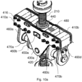
- Fig. 10a shows the nut assembly 400 of Fig. 5 from a different angle.
- the piezoelectric strain gauge 480 may be attached to the nut assembly 400 at a different location from the junction plates 410a, 410b.
- the piezoelectric strain gauge 480 may be attached to one of the arm portions 460a, 460b, 460c, 460d.
- Fig. 10b shows an example signal 700 taken from the piezoelectric strain gauge 480 when the piezoelectric strain gauge 480 is located as shown in Fig. 10a .
- voltage is shown on the y-axis and is measured against time, shown on the x-axis.
- the strain gauge may measure background vibrations 710 experienced by the actuator 200. It is to be understood that background vibrations are those vibrations which the actuator may experience under normal use.
- the background vibrations 710 may always be present during normal use, the background vibrations are measurable with the strain gauge. In the present example shown in Fig. 10b , the background vibrations 710 have a regular and repetitive signature.
- the piezoelectric strain gauge 480 is configured such that, when in the position shown, it is capable of measuring the shock generated by the loading of the secondary load path but not the loading.
- the shock generated by the loading of the secondary load path will be transmitted through the actuator 200 such that it can be measured by the piezoelectric strain gauge 480.
- the shock has a signature in the signal data of a sharp increase in the voltage amplitude. This is shown by the increase in the amplitude 730.
- the shock is damped. This damping of the shock is visible in the signal data as an overall decrease in the voltage amplitude after the initial shock increase 730.
- the actuator 200 will still experience background vibrations after the secondary load path is loaded, as shown in Fig 10b .
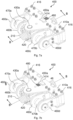
- Figs. 11a and 11b show schematic perspective views of the static portion 202 of the actuator shown in Figs 4a and 4b with a piezoelectric strain gauge 480 (which could in some examples be a system 600 such as the system of Fig. 8 including the piezoelectric strain gauge 480) attached thereto at different locations.
- a piezoelectric strain gauge 480 (which could in some examples be a system 600 such as the system of Fig. 8 including the piezoelectric strain gauge 480) attached thereto at different locations.
- the shock generated will be transmitted through the actuator, and therefore will be measurable by a piezoelectric strain gauge 480 attached on the static portion 202.
- the piezoelectric strain gauge 480 is attached to the secondary portion 202b of the static portion 202.
- the piezoelectric strain gauge 480 is attached to the primary portion 202a of the static portion 202.
- the piezoelectric strain gauge 480 may be attached at a different region on the primary portion 202a or secondary portion 202b
- the strain gauge 480 or the system 600 for identifying a failure of the primary load path in an actuator may be retrofitted without requiring disassembly of the nut assembly 400.
- the type of strain gauge is not limited to a piezoelectric strain gauge.
- the strain gauge may be, but is not limited to, a foil strain gauge, a piezoelectric strain gauge, a piezoresistive strain gauge or a capacitive strain gauge.
- the strain gauge 480 may be mounted to a support member. In any of the following examples, the strain gauge 480 may be mounted at any location on the support member 482. In any of the following examples, the strain gauge 480 may be mounted on a surface of the support member 482 which faces away from the actuator when mounted thereto.
- An example arrangement is shown in Fig. 12 .
- the support member may take the form of a plate. In the present example, the strain gauge 480 is attached to a plate 482.
- the plate 482 may be rigid.
- the plate 482 may be constructed from a metal such as aluminium or stainless steel.
- the support member may be formed from the same material as the junction plates. In other examples, the support member may be formed from a different material than the junction plates.
- the support member is shown as generally rectangular in shape. However, in other examples, the support member may take any suitable shape. For example, the support member may be triangular, oval, or pill-shaped.
- the support member may be in the form of a housing 600 such as that described above with the strain gauge 480 contained therein.
- the housing may be configured to protect the strain gauge.
- the support member 482 may be retrofitted to the actuator 200 using pre-existing means. That is, existing parts of the actuator may be used to secure the support to the actuator.
- the plate 482 may be retrofitted to the actuator using one or more fasteners 416 which are used to secure the junction plates 410a, 410b and arm portions 460a, 460b, 460c, 460d together.
- the plate 482 may comprise one or more holes.
- the one or more fasteners 416 may be temporarily removed so that the plate 482 may be placed in position so that the one of more holes align with the one or more holes from which the fasteners 416 have been removed.
- the one or more fasteners 416 may then be replaced, so as to pass through the one or more holes in the plate, and fastened so as to secure the plate 482 to the actuator 200. It is to be understood that due to the inherent thickness of the plate 482, the fasteners 416 may need to be replaced with longer fasteners. In some examples, the plate may be further secured with an adhesive, or with adhesive alone.
- the plate 482 since the plate 482 is in direct contact with the nut assembly 400, the shock can still be measured by the piezoelectric strain gauge 480 since the shock will be transferred to the plate 482. It is believed that the plate 482 has a resonant frequency which makes the background frequencies, as measured by the strain gauge more predictable. That is, the background vibration is known and will have a regular and repetitive signature.
- the support member may comprise an impact portion 484 configured to contact the secondary trunnion 450a, 450b.
- the impact portion 484 is configured so that, upon failure of the primary load path, a leading edge 486 of the impact portion 484 will impact the secondary trunnion 450a, 450b before the junction plates 410a, 410b impact the respective secondary trunnions 450a, 450b. This may be achieved by configuring the clearance between the leading edge 486 and the respective secondary trunnion 450a, 450b to be less than the clearance between the inner edges defined by the openings 414a, 414b and the secondary junctions 450a, 450b in normal operation. That is, in some examples, the impact portion 484 may overhang the opening 414a, 414b of the junction plate 410a, 410b.
- the impact portion 484 is configured so that, upon failure of the primary load path, a leading edge 486 of the impact portion 484 will impact the secondary trunnion 450a, 450b simultaneously with the junction plates 410a, 410b impacting the respective secondary trunnions 450a, 450b.
- the impact portion 484 is shown as a rectangular protrusion with a straight leading edge 486.
- the protrusion may take any other suitable shape, for example, curved or triangular.
- the leading edge 486 may be shaped so as to complement the corresponding edge of the secondary trunnion which it impacts.
- the support member may form a housing and comprise a protrusion.
- the support member may be impacted by a different part of the secondary nut than a secondary trunnion.
- the secondary nut may comprise a separate radially outwardly extending member that extends either through an opening 412a, 414b in respective junction plates 410a, 410b or through a separate opening in the junction plate. Upon failure of the primary load path, the support member will be impacted by the radially outwardly extending member.
- the strain gauge 480 may be attached to the impact portion 484 rather than elsewhere on the support member 482.
- the impact portion 484 may be configured so that the strain gauge 480 may be attached thereto.
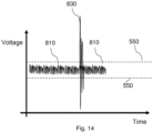
- Fig. 14 shows example strain gauge signal data when the primary load path fails or in other words when the secondary load path is loaded for the example shown in Fig. 13 .
- the peak amplitude 830 is much higher than that recorded in other examples and shown for example in Figs. 9 and 10b .
- the shock signature may be clearer for one or more reasons. Vibrations in parts of the actuator are caused by impact with the trunnions 450a, 450b.
- the junction plates 410a, 410b and the support member 482 may be made from the same material. However, each of the junction plates 410a, 410b may be thicker than the support member 482. Since the junction plates 410a, 410b are thicker than the support member 482, vibrations will be more readily damped by the junction plate than by the support member.
- the shock signature obtained in the support member may be clearer than that obtained in either support member and the vibrations measured by the strain gauge 480 attached directly to the support member 482 may be higher than those measured when attached to a junction plate 410a, 410b due to the lower damping effect of the support member. That is, the support member 482 improves the clarity of the measured signal since the vibrations thereof are less damped. It is to be understood that the junction plates 410a, 410b may be thicker than the support member 482 due to the requirement for the junction plates 410a, 410b to be structural in nature.
- the shock signature may be clearer for one or more reasons. As explained above, the relative thickness of the support member 482 compared to each junction plate 410a, 410b may improve the clarity of the shock signature. Additionally, or alternatively, it is to be understood that the shock will be damped further from the shock generating region. Therefore, by placing the strain gauge 480 as close as possible to the shock generating region, the shock signature will be most clear since the shock has yet to be significantly damped.
- the actuator may comprise a processor configured to process signal data obtained by the strain gauge.
- the processor is configured to identify a shock, as described above.
- Fig. 9 it is to be understood that the following explanation may be applicable to any of the presented signal data.
- the processor may be mounted onto the support member, as described above.
- the support member is in the form of a housing, as described above, the processor may be contained within the housing.
- the strain gauge signal data may be compared to a pre-determined threshold value which is indicative of primary load path failure.
- the pre-determined threshold may be determined by analysing and characterising background vibrations shown in the strain gauge signal data during normal use. That is, background vibrations measured, in flight for example when the primary load path is loaded, under normal operation. Data from multiple flights may be combined into a single data set for analysis and characterisation, as set out below.
- the predetermined threshold is illustrated by two horizontal dashed lines 550 of constant voltage. It is to be understood that the shown thresholds are purely explanatory, and that the thresholds may be more or less restrictive than shown. As shown in Fig. 9 , the strain gauge signal data may exceed the predetermined threshold more than once. That is, due to the oscillatory nature of the data, the peak amplitudes in the strain gauge signal data due to the shock will exceed the predetermined threshold.
- the pre-determined threshold may be determined by calculating the mean and standard deviation of the voltage amplitude for the background vibrations, and setting the pre-determined threshold value equal to n-standard deviations, wherein n is any real number. That is, measured strain gauge amplitude data exceeding n-standard deviations from the mean background amplitude would indicate failure of the primary load path, and loading of the secondary load path. It is to be understood that since that signal is oscillatory in nature, the predetermined threshold may comprise two thresholds: the mean background amplitude plus n-standard deviations and the mean background amplitude minus n-standard deviations. Therefore, exceeding may be taken to mean being greater than the mean background amplitude plus n-standard deviations or being less than the mean background amplitude minus n-standard deviations.
- the pre-determined threshold may be determined by calculating the mean and standard deviation of the frequency of the background vibrations, and setting the pre-determined threshold value equal to n-standard deviations, wherein n is any real number. That is, measured strain gauge frequency data exceeding n-standard deviations from the mean background frequency would indicate failure of the primary load path, and loading of the secondary load path.
- both the amplitude and frequency pre-determined thresholds may be used.
- the pre-determined threshold may be determined in a different way. For example, the mean peak value of the background peak amplitudes may be determined, and the pre-determined threshold set as n-mean peak value. That is, measured strain gauge amplitude data exceeding n- mean peak value would indicate failure of the primary load path, and loading of the secondary load path.
- the background vibrations may be determined using computational modelling techniques, from which the pre-determined threshold may be determined as described above.
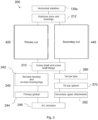
- the strain gauge signal data is communicated to the processor in real time.
- the processor is configured to compare the strain gauge signal data in real time with the pre-determined threshold.
- the pre-determined threshold may be determined using any of the methods above.
- the processor will compare strain gauge signal amplitude data to the pre-determined threshold value. In the present example, the processor will determine whether the strain gauge signal amplitude data exceeds the predetermined threshold.
Landscapes
- Engineering & Computer Science (AREA)
- General Engineering & Computer Science (AREA)
- Mechanical Engineering (AREA)
- Aviation & Aerospace Engineering (AREA)
- Physics & Mathematics (AREA)
- General Physics & Mathematics (AREA)
- Manufacturing & Machinery (AREA)
- Transportation (AREA)
- Automation & Control Theory (AREA)
- Transmission Devices (AREA)
Abstract
There is provided a system for identifying a failure of the primary load path in an actuator (200). The actuator (200) comprises a screw shaft (210) and a nut assembly (400) moveable along the screw shaft (210). The nut assembly (400) comprises a primary nut (420) for transmitting load through the actuator (200) along a primary load path, and a secondary nut (440) for transmitting load through the actuator (200) along a secondary load path. The nut assembly (400) is configured such that, in normal operation, the secondary nut (440) is not engaged with the screw shaft (210) and load is transmitted through the actuator (200) along the primary load path, and such that, upon failure of the primary load path, the secondary nut (440) is configured to engage the screw shaft (210) and transmit load through the actuator (200) along the secondary load path. The system comprises a strain gauge (480) configured to be mounted to the actuator (200) and to measure vibrations of the actuator (200), and a processor (608) configured to identify a failure of the primary load path from the measured vibrations. The strain gauge is a piezoelectric strain gauge. There is also provided a method for identifying a failure of the primary load path in an actuator (200).
Description
- The present disclosure relates to a system for identifying a failure of the primary load path in an actuator and to an actuator including such a system, for example a trimmable horizontal stabiliser actuator ("THSA") for an aircraft, wherein the actuator includes a primary load path and a secondary load path that is configured to carry the load of the actuator upon failure of the primary load path.
- Actuators typically provide a structural link between stationary parts of the actuator (and the object to which the actuator is attached), which provide a driving force for the actuator, and the moving parts of the actuator that actuate a component. Various loads are transmitted from the component to the stationary parts of the actuator via the moving parts thereof. Most actuators provide this structural link in the form of a load path, along which various tolerances are provided between components to account for excessive loading in use.
- An example of such an actuator is a trimmable horizontal stabiliser actuator ("THSA") for an aircraft, which is submitted to various aerodynamic loads in use (e.g., flutter caused by turbulence). In some cases, such actuators comprise a primary load path that is configured to support aerodynamic loads in normal condition, and a secondary load path that is configured to support aerodynamic loads upon failure of the primary load path. During normal use, the secondary load path is intended to remain in an unloaded condition.
- It is desired to provide means for detecting and / or identifying the failure of the primary load path, and the subsequent loading of the secondary load path.
- According to a first aspect of the disclosure, there is provided a system for identifying a failure of the primary load path in an actuator. The actuator comprises a screw shaft and a nut assembly moveable along the screw shaft. The nut assembly comprises a primary nut for transmitting load through the actuator along a primary load path, and a secondary nut for transmitting load through the actuator along a secondary load path. The nut assembly is configured such that, in normal operation, the secondary nut is not engaged with the screw shaft and load is transmitted through the actuator along the primary load path, and such that, upon failure of the primary load path, the secondary nut is configured to engage the screw shaft and transmit load through the actuator along the secondary load path. The system comprises a strain gauge configured to be mounted to the actuator and to measure vibrations of the actuator, and a processor configured to identify a failure of the primary load path from the measured vibrations. The strain gauge is a piezoelectric strain gauge.
- In any example of the disclosure, the strain gauge may be mounted on a support member configured to be mounted to the actuator.
- In any example of the disclosure, the strain gauge and the processor may be connected with a wired connection. In any example of the disclosure, the strain gauge and the processor may be connected wirelessly.
- According to another aspect of the disclosure, there is provided an actuator. The actuator comprises a screw shaft and a nut assembly moveable along the screw shaft. The nut assembly comprises a primary nut for transmitting load through the actuator along a primary load path, and a secondary nut for transmitting load through the actuator along a secondary load path. The nut assembly is configured such that, in normal operation, the secondary nut is not engaged with the screw shaft and load is transmitted through the actuator along the primary load path, and such that, upon failure of the primary load path, the secondary nut is configured to engage the screw shaft and transmit load through the actuator along the secondary load path. The actuator comprises a system of any of the above examples. The strain gauge or the support member is mounted to the actuator.
- In any example of the disclosure, the strain gauge or the support member may be mounted on the nut assembly.
- In any example of the disclosure, the secondary nut may comprise a pair of trunnions.
- In any example of the disclosure, the nut assembly may comprise a pair of junction plates.
- In any example of the disclosure, each of the junction plates may comprise an opening for receiving a respective trunnion of the pair of trunnions.
- In any example of the disclosure, in normal operation, the trunnions may not contact respective openings in the junction plate.
- According to another aspect of the disclosure, there is provided a system for identifying a failure of the primary load path in an actuator. The actuator comprises a screw shaft and a nut assembly moveable along the screw shaft. The nut assembly comprises a primary nut for transmitting load through the actuator along a primary load path, and a secondary nut for transmitting load through the actuator along a secondary load path. The nut assembly is configured such that, in normal operation, the secondary nut is not engaged with the screw shaft and load is transmitted through the actuator along the primary load path, and such that, upon failure of the primary load path, the secondary nut is configured to engage the screw shaft and transmit load through the actuator along the secondary load path. The system comprises a support member configured to be mounted to the nut assembly, wherein, upon failure of the primary load path, the support member is configured to be impacted by the secondary nut and to vibrate due to the impact. The system comprises a strain gauge mounted to the support member and configured to measure vibrations of the support member, and a processor configured to identify a failure of the primary load path from the measured vibrations.
- In any example of the disclosure, the support member may comprise an impact portion configured such that, upon failure of the primary load path, the impact portion is impacted by a component of the secondary nut before or simultaneously with the loading of the secondary load path.
- In any example of the disclosure, the strain gauge may be mounted on the impact portion.
- In any example of the disclosure, the strain gauge may be one of a piezoelectric strain gauge, a piezoresistive strain gauge, a capacitive strain gauge or a metal foil strain gauge.
- In any example of the disclosure, the processor may be mounted on the support member.
- In any example of the disclosure, the impact portion may be a protrusion.
- In any example of the disclosure, the strain gauge may be attached and /or mounted directly to the support member.
- In any example of the disclosure, the strain gauge may be attached anywhere on the support member.
- In any example of the disclosure, the strain gauge may be attached on the support member on a surface facing away from the nut assembly.
- According to another aspect of the disclosure, there is provided an actuator. The actuator comprises a screw shaft and a nut assembly moveable along the screw shaft. The nut assembly comprises a primary nut for transmitting load through the actuator along a primary load path, and a secondary nut for transmitting load through the actuator along a secondary load path. The nut assembly is configured such that, in normal operation, the secondary nut is not engaged with the screw shaft and load is transmitted through the actuator along the primary load path, and such that, upon failure of the primary load path, the secondary nut is configured to engage the screw shaft and transmit load through the actuator along the secondary load path. The actuator comprises the system of any of the above examples, wherein the support member is mounted to the nut assembly.
- In any example of the disclosure, the nut assembly may comprise a junction plate configured to form a portion of the primary load path in normal operation, and further configured to form a portion of the secondary load path upon failure of the primary load path.
- In any example of the disclosure, the strain gauge or the support member may be mounted on the junction plate.
- In any example of the disclosure, the secondary nut may comprise an outwardly extending member, and the support member may be configured to be impacted by the outwardly extending member.
- In some examples, the outwardly extending member is a pin.
- In some examples, the secondary nut comprises a pair of trunnions, and the outwardly extending member is one of the trunnions.
- In some examples, the outwardly extending member extends through an opening in the junction plate.
- In any example of the disclosure, the processor may be configured to compare the measured vibrations to a predetermined threshold value to identify the failure of the primary load path.
- In any example of the disclosure, the system may comprise a housing configured to protect the strain gauge.
- In any example of the disclosure, the actuator may be a linear actuator.
- In any example of the disclosure, the actuator may be an electromechanical linear actuator.
- In any example of the disclosure, the actuator may be a trimmable horizontal stabiliser actuator.
- In any example of the disclosure, the actuator may comprise a static portion configured to be attached to a fixed structure, and the nut assembly may be moveable relative to the static portion.
- According to another aspect of the disclosure, there is provided an aircraft comprising a system or an actuator of any of the above examples.
- According to another aspect of the disclosure, there is provided a method for identifying a failure of the primary load path in an actuator. The actuator comprises a screw shaft and a nut assembly moveable along the screw shaft. The nut assembly comprises a primary nut for transmitting load through the actuator along a primary load path, and a secondary nut for transmitting load through the actuator along a secondary load path. The nut assembly is configured such that, in normal operation, the secondary nut is not engaged with the screw shaft and load is transmitted through the actuator along the primary load path, and such that, upon failure of the primary load path, the secondary nut is configured to engage the screw shaft and transmit load through the actuator along the secondary load path. The method comprises measuring vibrations of the actuator by a piezoelectric strain gauge mounted to the actuator, and processing the measured vibrations to identify a failure of the primary load path.
- According to another aspect of the disclosure, there is provided a method for identifying a failure of the primary load path in an actuator. The actuator comprises a screw shaft and a nut assembly moveable along the screw shaft. The nut assembly comprises a primary nut for transmitting load through the actuator along a primary load path, and a secondary nut for transmitting load through the actuator along a secondary load path. The nut assembly is configured such that, in normal operation, the secondary nut is not engaged with the screw shaft and load is transmitted through the actuator along the primary load path, and such that, upon failure of the primary load path, the secondary nut is configured to engage the screw shaft and transmit load through the actuator along the secondary load path. The method comprises: mounting a support member to the nut assembly, wherein, upon failure of the primary load path, the support member is configured to be impacted by the secondary nut and to vibrate due to the impact; measuring vibrations of the support member by a strain gauge mounted to the support member, and processing the measured vibrations to identify a failure of the primary load path.
- In any example of the disclosure, the processing the measured vibrations may comprise comparing the measured vibrations to a pre-determined threshold value, and identifying a failure of the primary load path when the measured vibrations exceed the predetermined threshold value.
- In any example of the disclosure, the method may comprise notifying a user and / or activating an alarm if primary load path failure is determined.
- According to another aspect of the disclosure, there is provided a method for modifying an actuator. The actuator comprises a screw shaft and a nut assembly moveable along the screw shaft. The nut assembly comprises a primary nut for transmitting load through the actuator along a primary load path, and a secondary nut for transmitting load through the actuator along a secondary load path. The nut assembly is configured such that, in normal operation, the secondary nut is not engaged with the screw shaft and load is transmitted through the actuator along the primary load path, and such that, upon failure of the primary load path, the secondary nut is configured to engage the screw shaft and transmit load through the actuator along the secondary load path. The method comprises installing a system of any of the above examples on the actuator.
- In some examples, the actuator comprises a fastener, and the step of installing the system of any of the above examples on the actuator comprises removing the fastener, positioning the system on the actuator, and replacing the fastener so as to secure the system to the actuator.
- Various examples will now be described, by way of example only, and with reference to the accompanying drawings in which:
-
Fig. 1 shows a schematic perspective view of the tail end of an aircraft; -
Fig. 2 shows a schematic view of an example actuator for use with a system according to an example of the disclosure; -
Fig. 3 shows one example of a primary and secondary load path of the actuator ofFig 2 ; -
Figs. 4a and 4b show examples of the primary and secondary load paths in an example actuator for use with a system according to the disclosure, in which the primary load path is shown inFig 4a , while the secondary load path is shown inFig 4b ; -
Fig. 5 shows a schematic perspective view of a nut assembly of the actuator ofFigs. 4a and 4b and including a portion of the screw shaft for reference; -
Fig. 6 shows a schematic cross-sectional view of the nut assembly ofFig. 5 and including a portion of the screw shaft for reference; -
Figs. 7a, 7b , and7c show schematic perspective views of the nut assembly ofFig. 5 with respective strain gauges attached thereto; -
Fig. 8 shows a schematic side view of a system according to an example of the disclosure; -
Fig. 9 shows example strain gauge signal data; -
Fig. 10a shows a schematic perspective view of the nut assembly ofFig. 5 with a strain gauge attached thereto; -
Fig.10b shows example strain gauge signal data for the example shown inFig. 10a ; -
Figs. 11a and 11b show a schematic perspective view of the static portion of the actuator shown inFigs 4a and 4b with a strain gauge attached thereto; -
Fig. 12 shows a schematic perspective view of the nut assembly ofFig. 5 with system according to an example of the disclosure attached thereto; -
Fig. 13 shows a schematic perspective view of the nut assembly ofFig. 5 with a system according to a second example of the disclosure attached thereto; and -
Fig.14 shows example strain gauge signal data for the example shown inFig. 13 . - The present disclosure relates to actuators, such as for example a flight control actuator, such as a trimmable horizontal stabiliser actuator ("THSA") for an aircraft. In any example of the disclosure, the actuator includes a primary load path and a secondary load path that is configured to carry the load of the actuator upon failure of the primary load path. In any example of the disclosure, the actuator includes a strain gauge and is configured to identify failure of the primary load path based on vibrations recorded by the strain gauge.
-
Fig. 1 shows a schematic perspective view of thetail end 100 of an aircraft (not shown). The aircraft includes avertical stabiliser 120 extending upwardly from theaircraft fuselage 110 and respectivehorizontal stabilisers aircraft fuselage 110 on respective sides of the aircraft. One ormore rudders 122 are provided at the trailing edge 124 (i.e. the rear face) of thevertical stabiliser 120 and one ormore elevators 132 are provided on the trailing edge 134 (i.e. the rear face) of eachhorizontal stabiliser vertical stabilisers 120,horizontal stabilisers rudders 122 andelevators 132 are adapted to be moved by actuation systems (not shown) to control movement of the aircraft. - The actuation system typically includes a control system (not shown) and a number of actuators (not shown in
Fig. 1 ) configured to move the respectivevertical stabilisers 120,horizontal stabilisers rudders 122 andelevators 132 under the control of the control system. - The actuators may take a number of different forms depending for example on the type and size of aircraft in which they are used. In one example, one or more electromechanical actuators, more specifically electromechanical linear actuators may be provided in the actuation system. An example of an electromechanical linear actuator which may be used to move one of the
horizontal stabilisers -
Fig. 2 shows anexample actuator 200, which may be a flight control actuator, such as a trimmable horizontal stabiliser actuator ("THSA"), as described above. Theactuator 200 may include a primary load path with a screw shaft 210 (e.g., that is hollow) connected at an end thereof, for example at its upper end as shown, to the aircraft via astatic portion 202 including a first joint system 340 (e.g., a Carden joint system) joining with first aircraft structural elements S1. The primary load path further includes anut assembly 400 mounted on thescrew shaft 210, and thenut assembly 400 is connected to a moveable component, for example, astabiliser Nut assembly 400 is described in more detail below with respect toFigs. 5 and6 . - The secondary load path may be provided by means of a
tie bar 390 that is within thescrew shaft 210. Thetie bar 390 is terminated at a first end by a male portion, in this case optionally taking the form of aspherical head 370, which is mounted within a female portion on afastening piece 380, optionally taking the form of arecess 310. Thefastening piece 380 may be connected to the structure of the aircraft via second aircraft structural elements S2. The actuator may also include some means for preventing motion of thenut assembly 400 relative to thescrew shaft 210 and/or for fixing thestabiliser 130a/secondjoint system 136 in place when the primary load path fails. Thus, thenut assembly 400, also includes secondary load path elements that are enabled for use upon failure of the primary load path. - It will be appreciated from
Fig. 2 that movement of thespherical head 370 may be restricted by the upper and lower shoulders of therecess 310. Consequently, thestabiliser 130a can either be safely held in a single position (in the case where thenut assembly 400 locks in place) or in some arrangements it might be permitted to continue normal movement should thetie bar 390 be connected with thescrew shaft 210 in such a way as to permit continued rotation of thescrew shaft 210 even after failure preventing it from carrying axial loads. - During normal use, e.g., without any failure, the loading for the
actuator 200 is carried via the primary load path. In the event of a failure of the primary load path the loading is transferred to the secondary load path. -
Fig. 3 shows one possible arrangement for the primary and secondary load paths of theactuator 200, in which a component (e.g., a horizontal stabiliser) 130a, 130b is connected by optional arms andbushings 212 to aprimary nut 420 which connects it to thescrew shaft 210. - As described in more detail below, the
primary nut 420 may includeprimary trunnions Fig. 6 ), and theprimary nut 420 may comprise a ballscrew assembly (not shown). - The
primary nut 420 forms part of thelower attachment 400 of theactuator 200 that is dedicated to the primary load path. At the upper end of the actuator 200 a joint system 240 (such as a Cardan joint system) will typically include noback elements 242 along with the primaryload path gimbal 244, which may be coupled to theaircraft structure 246. During normal use, e.g., without any failure, the loading for theactuator 200 is carried via the primary load path. - In the event of a failure of the primary load path the loading is transferred to the secondary load path. In this case at the
lower attachment 400 thehorizontal stabiliser 130a is connected by the (optional) stabiliser arms andbushings 212 to asecondary nut 440. - The
secondary nut 440 typically comprises a screw thread that is arranged to lock with the threads of thescrew shaft 210, preventing movement of thehorizontal stabiliser 130a when the secondary load path is engaged. As described in more detail below (seeFig. 4 ), thesecondary nut 440 may comprisesecondary trunnions junction plates secondary nut 440 may comprise screw threads (not shown) which can be joined to the thread of thescrew shaft 210 when the secondary load path is engaged. - From the
secondary nut 440 the load in the secondary load path may be transmitted via thescrew shaft 210 along the tie bar rod 390 (Fig. 2 ) and optionally through the male end of thetie bar rod 390, which in this example is atie bar sphere 370, and to an uppersecondary attachment 202. Thus, thesecondary nut 440 forms part of thelower attachment 400 of theactuator 200 that is dedicated to the secondary load path. - Examples of the primary and secondary load paths in an actuator according to the disclosure are shown in
Figs. 4a and 4b . The primary load path is shown inFig. 4a , which illustrates the actuator 200 operating under normal operation. While the secondary load path is shown inFig. 4b , which illustrates the actuator 200 operating after failure of the primary load path. -
Fig. 4a shows theactuator 200 comprising astatic portion 202 that is configured to attach to a stationary object, for example an aircraft fuselage (not shown inFigs. 4a and 4b ) as described above. Theactuator 200 further comprises a motor (not shown) or other driving means configured to rotate thescrew shaft 210 about an axis A. - The
actuator 200 further comprises anut assembly 400 as previously described that is configured to move axially along thescrew shaft 210 upon rotation thereof. A component, for example ahorizontal stabiliser 130a, may be operatively connected to thenut assembly 400, such that movement of thenut assembly 400 along the axis A causes actuation of the component by theactuator 200. Astop 220 located at one end of thescrew shaft 210 is also shown inFigs. 4a and 4b . Thestop 220 prevents thenut assembly 400 from detaching from thescrew shaft 210. - The
static component 202 may comprise aprimary portion 202a and asecondary portion 202b, which may be connected to different parts of the stationary object or may be connected via different connections. Thestatic component 202 may also be referred to as theupper attachment 202. - The
nut assembly 400 comprises aprimary nut 420 and asecondary nut 440, both of which may cooperate with thescrew shaft 210 in order to drive thenut assembly 400 upon rotation thereof. This is described in more detail below. - During normal operation, as shown in
Fig 4a , load is transferred from the component to which theactuator 200 is attached to theprimary nut 420, and then to theprimary portion 202a of thestatic component 202 via thescrew shaft 210. This is referred to herein as a primary load path and is indicated by the arrows A1. - Upon failure of one or more components of the primary load path (e.g., rupturing of the
primary nut 420 or one or more parts thereof) a secondary load path (indicated by the arrows A2 inFig. 4b ) is provided that is configured to transmit load between thestatic component 202 and the component to which theactuator 200 is attached. -
Fig. 5 is a perspective view which shows thenut assembly 400 in more detail, and includes a portion of thescrew shaft 210 for reference.Fig. 6 shows a cross-sectional side view of thenut assembly 400 ofFig. 5 taken along line B-B when the secondary load path is engaged as described further below. - As mentioned above, the
nut assembly 400 comprises aprimary nut 420. In the example shown, theprimary nut 420 is mounted coaxially on thescrew shaft 210. In some examples, theprimary nut 420 is part of a suitable ballscrew assembly (or similar means) and cooperates with thescrew shaft 210. In some examples, the ballscrew assembly comprises balls orball bearings 422 arranged between thescrew shaft 210 and theprimary nut 420 so as to couple thescrew shaft 210 and theprimary nut 420 in the ballscrew assembly. In some examples, theprimary nut 420 comprises a pair ofprimary trunnions primary nut 420 andprimary trunnions primary nut 420 andprimary trunnions primary trunnions primary nut 420 in opposite directions to each other and / or from opposite sides of theprimary nut 420. In any example of the disclosure, theprimary trunnions primary trunnions primary trunnions - The
nut assembly 400 comprises asecondary nut 440. In the example shown, thesecondary nut 440 is mounted coaxially with thescrew shaft 210. In some examples, thesecondary nut 440 comprises ascrew thread 441 for cooperating with thescrew shaft 210. In the example shown, thesecondary nut 440 comprises a pair ofsecondary trunnions secondary trunnions secondary trunnions secondary nut 440 does not transmit load under normal operation (i.e. when the primary load path is loaded). - In the example shown, the
nut assembly 400 comprises a pair ofjunction plates junction plates secondary nut 440. Thejunction plates junction plates junction plates junction plates openings primary trunnions nut assembly 400 may comprisebushings primary trunnions bushings primary trunnions openings Fig 6 , one or more of thebushings flange inner surface junction plates - In the example shown, apertures in the
junction plates openings secondary trunnions openings secondary trunnions respective junction plates - In the present example, the
primary trunnions secondary trunnions outer surfaces junction plates primary trunnions secondary trunnions outer surfaces junction plates - In the example shown, the
nut assembly 400 comprisesarm portions nut assembly 400 between thejunction plates arm portions arm portions screw shaft 210 to a second pair ofarm portions respective connectors Connectors primary nut 420 causes actuation of the moveable component. The arrangement comprising thejunction plates arm portions connectors - In the example shown, the
primary nut 420, thesecondary nut 440 andjunction plates secondary nut 440 during normal operation. In the example shown, this is achieved by providing a clearance around thesecondary trunnions secondary trunnions openings - In the following, failure of the primary load path and subsequent loading of the secondary load path in one example of the disclosure is described. In the example shown, clearance provided between the
secondary trunnions respective junction plates junction plates arm portions connectors secondary nut 440 upon failure of the primary load path. The connection assembly will therefore continue to move axially relative to thesecondary nut 440 until the inner surfaces of theopenings junction plates secondary trunnions secondary trunnions secondary nut 440 and the connection assembly. Consequently, the load is transmitted through thesecondary nut 440 once the inner surfaces of theopenings junction plates secondary trunnions junction plates secondary trunnions - Due to the impact of the
junction plates secondary trunnions - It is to be understood that, in any example of the disclosure, the system may be used with a linear actuator, an electromechanical linear actuator or a trimmable horizontal stabiliser actuator.
- In the following described examples, a system for identifying a failure of the primary load path in an actuator is provided in which a piezoelectric strain gauge is used to detect the shock. In any of these examples, the piezoelectric strain gauge may be a piezoelectric omnidirectional strain sensor. One such piezoelectric omnidirectional strain sensor which may be used is a Dragonfly® DGF-OMN-AA20206-10 Piezoelectric omnidirectional strain sensor manufactured by Wormsensing. The strain gauge may behave as a charge generator in parallel with a capacitor and a leakage resistor. The strain gauge may be passive and may not require any power supply. In some examples, the strain gauge can be operated either in charge mode (using a charge amplifier) or voltage mode (direct measurement). The strain gauge of some examples is made from a thin piezoelectric ceramic. A sensing element of the strain gauge typically has a thickness of less than 10 µm. The thickness may be between 1 µm and 20 µm, or between 5 µm and 15 µm. These thicknesses enable the sensing element to have the flexibility and stretchability of a 2D material. The crystalline nature of the sensing element of some examples results in high durability and repeatability.
- For typical metal foil strain gauges, sensitivities are limited to about 1 to 10 µdef, where µdef is the unit of microstrain. Strain (ε) is the ratio of change in length to the original length, therefore, microstrain is ε × 10-6. By comparison, a strain gauge of the type described above may enable measurements in the region of about 0.01 µdef, having a sensitivity at least one hundred times greater than a typical metal foil strain gauge.
-
Figs. 7a-c each show thenut assembly 400 shown inFig. 5 with apiezoelectric strain gauge 480 attached thereto. In the following examples, thepiezoelectric strain gauge 480 may be retrofitted to an existingactuator 200 as shown. That is, theactuator 200 requires no disassembly or only minor disassembly in order to attach thestrain gauge 480 to thenut assembly 400. -
Fig. 8 shows a schematic side view of asystem 600 for identifying a failure of the primary load path in an actuator, thesystem 600 including apiezoelectric strain gauge 480 such as that described above. As seen, thepiezoelectric strain gauge 480 can be mounted on aplate 602 which in turn can be mounted to a part of theactuator 200, for example, thejunction plate 410a. As described below, theplate 602 can be mounted to a part of theactuator 200 by a plurality offixings 604 such as screws or rivets. Ahousing 606 may be provided, for example mounted on theplate 602 or integral therewith. Thehousing 606 may be configured to protect, for example to enclose, thepiezoelectric strain gauge 480. Theplate 602 and thehousing 606 may be made of the same or different materials, including but not limited to metals. Awired connection 610 or a wireless connection may be provided between thepiezoelectric strain gauge 480 and a processor orcontroller 608 which may be provided in thehousing 606 as shown. Awired connection 612 or a wireless connection may be provided between the processor orcontroller 608 and the aircraft. In some examples, the processor may be provided externally of the housing, for example in an aircraft. Further, electronics for processing signals received from thepiezoelectric strain gauge 480 may also be provided in thesystem 600 and within thehousing 606. - In the example shown in
Fig 7a , thepiezoelectric strain gauge 480, or in some examples thesystem 600 including thepiezoelectric strain gauge 480, is attached to an outer surface of ajunction plate 410a. In the example shown, thepiezoelectric strain gauge 480 may be located to be aligned with thesecondary trunnion 450a in the axial direction. In other examples, thepiezoelectric strain gauge 480 may be offset such that it is not aligned with thesecondary trunnion 450a. In this example, thepiezoelectric strain gauge 480 is positioned such that thesecondary trunnion 450a is located axially between thepiezoelectric strain gauge 480 and theprimary trunnion 430a. - In the alternative example shown in
Fig 7b , thepiezoelectric strain gauge 480 is attached to an outer surface ofjunction plate 410a. In this example, thepiezoelectric strain gauge 480, or in some examples thesystem 600 including thepiezoelectric strain gauge 480, is located to be aligned with thesecondary trunnion 450a in the axial direction. In other examples, thepiezoelectric strain gauge 480 may be offset such that it is not aligned with thesecondary trunnion 450a. In this example, thepiezoelectric strain gauge 480 is positioned such that thepiezoelectric strain gauge 480 is located axially between thesecondary trunnion 450a and theprimary trunnion 430a. In this example, thepiezoelectric strain gauge 480 is located axially closer to thesecondary trunnion 450a than to theprimary trunnion 430a. In other examples, thepiezoelectric strain gauge 480 may be located equidistant between theprimary trunnion 430a andsecondary trunnion 450a. In other examples, thepiezoelectric strain gauge 480 may be located closer to theprimary trunnion 430a than to thesecondary trunnion 450a. - In the example shown in
Fig 7c , thepiezoelectric strain gauge 480, or in some examples thesystem 600 including thepiezoelectric strain gauge 480, is attached to an outer surface ofjunction plate 410a. In particular, thepiezoelectric strain gauge 480 is located to be axially offset from thesecondary trunnion 450a. In other examples, thepiezoelectric strain gauge 480 may be offset such that it is not aligned with thesecondary trunnion 450a. In this example, thepiezoelectric strain gauge 480 is positioned such that thesecondary trunnion 450a is located axially between thepiezoelectric strain gauge 480 and theprimary trunnion 430a. - It is to be understood that in any example, the
piezoelectric strain gauge 480 may be located anywhere on thejunction plate 410a. In some examples, thepiezoelectric strain gauge 480 may be attached tojunction plate 410b. - In other examples, rather than being attached by fixing means such as screws or rivets, for example via the plate and housing described above, the
piezoelectric strain gauge 480 may be attached to a part of theactuator 200, for example thejunction plate - In some examples, since the shock is transmitted throughout the actuator, the
piezoelectric strain gauge 480 may be attached to thestop 220. - As described above, upon failure of the primary load path, the secondary load path becomes loaded. In the present example, a shock (or in other word a vibration) is generated when the
junction plates secondary trunnions piezoelectric strain gauge 480. -
Fig. 9 shows anexample signal 500 taken from thepiezoelectric strain gauge 480 when thepiezoelectric strain gauge 480 is located on thejunction plate 410a as shown inFigs. 7a and 7b . InFig. 9 , voltage is shown on the y-axis and is measured against time, shown on the x-axis. Thestrain gauge 480 may measurebackground vibrations 510 experienced by theactuator 200. It is to be understood that background vibrations are those vibrations which the actuator may experience under normal use. It is to be understood that in any example, signal or signal data may be referred to as measured vibrations. - Since these
background vibrations 510 may always be present during normal use, the background vibrations are measurable with thestrain gauge 480. In the present example shown inFig. 9 , thebackground vibrations 510 have a regular and repetitive signature. It is to be understood that the background vibrations may be more or less regular and repetitive than shown inFig. 9 . For example, the measured voltage may vary more or less than shown dependent on where thestrain gauge 480 is located on thejunction plate 410a. - In the examples shown in
Figs. 7a and 7b , thepiezoelectric strain gauge 480 is configured such that, when in one of the positions shown, it is capable of measuring both the loading of thejunction plates secondary trunnions - The loading of the secondary load path, that is, the interaction between the
junction plates secondary trunnions piezoelectric strain gauge 480 is positioned as shown inFigs. 7a and 7b . Such loading may appear in the signal data as an increase in themean voltage 520 as compared to the average voltage caused by thebackground vibrations 510. It is to be understood that the increase in themean voltage 520 is caused by the deformation of thejunction plate junction plate piezoelectric strain gauge 480 is attached. This deformation may arise due to the impact of thejunction secondary trunnions - The shock generated by the loading of the secondary load path will be transmitted through the
actuator 200 such that it can be measured by thepiezoelectric strain gauge 480. The shock has a signature in the signal data of a sharp increase in the voltage amplitude, shown by the increase in theamplitude 530. As the shock is transmitted through theactuator 200, the shock is damped. This damping of the shock is visible in the signal data as an overall decrease in thevoltage amplitude 540 after theinitial shock increase 530. Theactuator 200 will still experience background vibrations after the secondary load path is loaded, as shown inFig 9 . -
Fig. 10a shows thenut assembly 400 ofFig. 5 from a different angle. In other examples, as shown inFig. 10a , thepiezoelectric strain gauge 480 may be attached to thenut assembly 400 at a different location from thejunction plates Fig. 10a , thepiezoelectric strain gauge 480 may be attached to one of thearm portions -
Fig. 10b shows anexample signal 700 taken from thepiezoelectric strain gauge 480 when thepiezoelectric strain gauge 480 is located as shown inFig. 10a . InFig. 10b , voltage is shown on the y-axis and is measured against time, shown on the x-axis. The strain gauge may measurebackground vibrations 710 experienced by theactuator 200. It is to be understood that background vibrations are those vibrations which the actuator may experience under normal use. - Since these
background vibrations 710 may always be present during normal use, the background vibrations are measurable with the strain gauge. In the present example shown inFig. 10b , thebackground vibrations 710 have a regular and repetitive signature. - In the example shown in
Fig. 10b , thepiezoelectric strain gauge 480 is configured such that, when in the position shown, it is capable of measuring the shock generated by the loading of the secondary load path but not the loading. - The shock generated by the loading of the secondary load path will be transmitted through the
actuator 200 such that it can be measured by thepiezoelectric strain gauge 480. The shock has a signature in the signal data of a sharp increase in the voltage amplitude. This is shown by the increase in theamplitude 730. As the shock is transmitted through theactuator 200, the shock is damped. This damping of the shock is visible in the signal data as an overall decrease in the voltage amplitude after theinitial shock increase 730. Theactuator 200 will still experience background vibrations after the secondary load path is loaded, as shown inFig 10b . -
Figs. 11a and 11b show schematic perspective views of thestatic portion 202 of the actuator shown inFigs 4a and 4b with a piezoelectric strain gauge 480 (which could in some examples be asystem 600 such as the system ofFig. 8 including the piezoelectric strain gauge 480) attached thereto at different locations. As described above, the shock generated will be transmitted through the actuator, and therefore will be measurable by apiezoelectric strain gauge 480 attached on thestatic portion 202. InFig 11a , thepiezoelectric strain gauge 480 is attached to thesecondary portion 202b of thestatic portion 202. InFig 11b , thepiezoelectric strain gauge 480 is attached to theprimary portion 202a of thestatic portion 202. In some examples, thepiezoelectric strain gauge 480 may be attached at a different region on theprimary portion 202a orsecondary portion 202b. - As described above, in any example of the disclosure, the
strain gauge 480 or thesystem 600 for identifying a failure of the primary load path in an actuator may be retrofitted without requiring disassembly of thenut assembly 400. - In any of the following examples, the type of strain gauge is not limited to a piezoelectric strain gauge. The strain gauge may be, but is not limited to, a foil strain gauge, a piezoelectric strain gauge, a piezoresistive strain gauge or a capacitive strain gauge.
- In some examples, the
strain gauge 480 may be mounted to a support member. In any of the following examples, thestrain gauge 480 may be mounted at any location on thesupport member 482. In any of the following examples, thestrain gauge 480 may be mounted on a surface of thesupport member 482 which faces away from the actuator when mounted thereto. An example arrangement is shown inFig. 12 . In some examples, the support member may take the form of a plate. In the present example, thestrain gauge 480 is attached to aplate 482. Theplate 482 may be rigid. Theplate 482 may be constructed from a metal such as aluminium or stainless steel. In some examples, the support member may be formed from the same material as the junction plates. In other examples, the support member may be formed from a different material than the junction plates. In the present example, the support member is shown as generally rectangular in shape. However, in other examples, the support member may take any suitable shape. For example, the support member may be triangular, oval, or pill-shaped. - In some examples, the support member may be in the form of a
housing 600 such as that described above with thestrain gauge 480 contained therein. The housing may be configured to protect the strain gauge. - In some examples, the
support member 482 may be retrofitted to theactuator 200 using pre-existing means. That is, existing parts of the actuator may be used to secure the support to the actuator. In the present example, theplate 482 may be retrofitted to the actuator using one ormore fasteners 416 which are used to secure thejunction plates arm portions plate 482 may comprise one or more holes. In the present example, the one ormore fasteners 416 may be temporarily removed so that theplate 482 may be placed in position so that the one of more holes align with the one or more holes from which thefasteners 416 have been removed. The one ormore fasteners 416 may then be replaced, so as to pass through the one or more holes in the plate, and fastened so as to secure theplate 482 to theactuator 200. It is to be understood that due to the inherent thickness of theplate 482, thefasteners 416 may need to be replaced with longer fasteners. In some examples, the plate may be further secured with an adhesive, or with adhesive alone. - It is to be understood that since the
plate 482 is in direct contact with thenut assembly 400, the shock can still be measured by thepiezoelectric strain gauge 480 since the shock will be transferred to theplate 482. It is believed that theplate 482 has a resonant frequency which makes the background frequencies, as measured by the strain gauge more predictable. That is, the background vibration is known and will have a regular and repetitive signature. - In some examples, the support member may comprise an
impact portion 484 configured to contact thesecondary trunnion impact portion 484 is configured so that, upon failure of the primary load path, aleading edge 486 of theimpact portion 484 will impact thesecondary trunnion junction plates secondary trunnions leading edge 486 and the respectivesecondary trunnion openings secondary junctions impact portion 484 may overhang theopening junction plate - In some examples, the
impact portion 484 is configured so that, upon failure of the primary load path, aleading edge 486 of theimpact portion 484 will impact thesecondary trunnion junction plates secondary trunnions - In the present example, the
impact portion 484 is shown as a rectangular protrusion with a straightleading edge 486. However, in other examples, the protrusion may take any other suitable shape, for example, curved or triangular. In some examples, theleading edge 486 may be shaped so as to complement the corresponding edge of the secondary trunnion which it impacts. In some examples, the support member may form a housing and comprise a protrusion. - It is to be understood that the support member may be impacted by a different part of the secondary nut than a secondary trunnion. In some examples, the secondary nut may comprise a separate radially outwardly extending member that extends either through an
opening respective junction plates - In some examples, for example shown in
Fig. 13 , thestrain gauge 480 may be attached to theimpact portion 484 rather than elsewhere on thesupport member 482. Theimpact portion 484 may be configured so that thestrain gauge 480 may be attached thereto. By providing thestrain gauge 480 directly on theimpact portion 484, the shock signature in the signal data is clearer than for an arrangement wherein thestrain gauge 480 is not attached to theimpact portion 484. -
Fig. 14 shows example strain gauge signal data when the primary load path fails or in other words when the secondary load path is loaded for the example shown inFig. 13 . As seen, thepeak amplitude 830 is much higher than that recorded in other examples and shown for example inFigs. 9 and10b . For example, an arrangement with thestrain gauge 480 being attached directly to a junction plate. Because the shock signature is clearer in such an arrangement, any suitable strain gauge, including but not limited to a foil strain gauge or a piezoelectric strain gauge may be mounted to the impact portion and used to identify the shock or vibrations caused by the failure of the primary load path and the impact portion impacting asecondary trunnion - In the examples where the
strain gauge 480 is attached directly to thesupport member 482, the shock signature may be clearer for one or more reasons. Vibrations in parts of the actuator are caused by impact with the trunnions 450a, 450b. Thejunction plates support member 482 may be made from the same material. However, each of thejunction plates support member 482. Since thejunction plates support member 482, vibrations will be more readily damped by the junction plate than by the support member. Consequently, the shock signature obtained in the support member may be clearer than that obtained in either support member and the vibrations measured by thestrain gauge 480 attached directly to thesupport member 482 may be higher than those measured when attached to ajunction plate support member 482 improves the clarity of the measured signal since the vibrations thereof are less damped. It is to be understood that thejunction plates support member 482 due to the requirement for thejunction plates - In the examples where the
strain gauge 480 is attached to the impact portion, the shock signature may be clearer for one or more reasons. As explained above, the relative thickness of thesupport member 482 compared to eachjunction plate strain gauge 480 as close as possible to the shock generating region, the shock signature will be most clear since the shock has yet to be significantly damped. - In some examples, the actuator may comprise a processor configured to process signal data obtained by the strain gauge. The processor is configured to identify a shock, as described above. In the following, reference is made to
Fig. 9 . However, it is to be understood that the following explanation may be applicable to any of the presented signal data. In some examples, the processor may be mounted onto the support member, as described above. In some examples where the support member is in the form of a housing, as described above, the processor may be contained within the housing. - As can be seen from
Fig. 9 , and discussed above,background vibrations 510 measured by the strain gauge are present in the signal data, and the shock is visually apparent in the signal data. It is desirable to automate shock identification. In some examples, the strain gauge signal data may be compared to a pre-determined threshold value which is indicative of primary load path failure. In some examples, the pre-determined threshold may be determined by analysing and characterising background vibrations shown in the strain gauge signal data during normal use. That is, background vibrations measured, in flight for example when the primary load path is loaded, under normal operation. Data from multiple flights may be combined into a single data set for analysis and characterisation, as set out below. - In
Fig. 9 , the predetermined threshold is illustrated by two horizontal dashedlines 550 of constant voltage. It is to be understood that the shown thresholds are purely explanatory, and that the thresholds may be more or less restrictive than shown. As shown inFig. 9 , the strain gauge signal data may exceed the predetermined threshold more than once. That is, due to the oscillatory nature of the data, the peak amplitudes in the strain gauge signal data due to the shock will exceed the predetermined threshold. - In some examples, the pre-determined threshold may be determined by calculating the mean and standard deviation of the voltage amplitude for the background vibrations, and setting the pre-determined threshold value equal to n-standard deviations, wherein n is any real number. That is, measured strain gauge amplitude data exceeding n-standard deviations from the mean background amplitude would indicate failure of the primary load path, and loading of the secondary load path. It is to be understood that since that signal is oscillatory in nature, the predetermined threshold may comprise two thresholds: the mean background amplitude plus n-standard deviations and the mean background amplitude minus n-standard deviations. Therefore, exceeding may be taken to mean being greater than the mean background amplitude plus n-standard deviations or being less than the mean background amplitude minus n-standard deviations.
- Additionally, or alternatively, the pre-determined threshold may be determined by calculating the mean and standard deviation of the frequency of the background vibrations, and setting the pre-determined threshold value equal to n-standard deviations, wherein n is any real number. That is, measured strain gauge frequency data exceeding n-standard deviations from the mean background frequency would indicate failure of the primary load path, and loading of the secondary load path. In some examples, both the amplitude and frequency pre-determined thresholds may be used.
- In some examples, the pre-determined threshold may be determined in a different way. For example, the mean peak value of the background peak amplitudes may be determined, and the pre-determined threshold set as n-mean peak value. That is, measured strain gauge amplitude data exceeding n- mean peak value would indicate failure of the primary load path, and loading of the secondary load path.
- In other examples, the background vibrations may be determined using computational modelling techniques, from which the pre-determined threshold may be determined as described above.
- It is to be understood that the pre-determined threshold may vary depending on the type of actuator in use, and therefore may need to be determined for each individual actuator. Such variance may be due to each actuator having its own resonant frequency.
- In the present example, the strain gauge signal data is communicated to the processor in real time. In the present example, the processor is configured to compare the strain gauge signal data in real time with the pre-determined threshold. The pre-determined threshold may be determined using any of the methods above.
- Where the pre-determined threshold is determined using amplitude data, the processor will compare strain gauge signal amplitude data to the pre-determined threshold value. In the present example, the processor will determine whether the strain gauge signal amplitude data exceeds the predetermined threshold.
- As the shock is damped throughout the actuator, the measured amplitudes will decrease and no longer exceed the predetermined threshold.
- In some examples, the processor may be configured to provide a notification, for example to a user, that the primary load path has failed. The notification may be notified on the basis that the strain gauge signal data exceeded the predetermined threshold, as described above for any example. In some examples, the actuator may comprise transmission means configured to transmit the notification to a user. While the disclosure has been described in detail in connection with only a limited number of examples, it should be readily understood that the disclosure is not limited to such disclosed examples. Rather, the disclosure can be modified to incorporate any number of variations, alterations, substitutions or equivalent arrangements not heretofore described, but which are commensurate with the scope of disclosure. Additionally, while various examples of the disclosure have been described, it is to be understood that aspects of the disclosure may include only some of the described examples. Accordingly the disclosure is not to be seen as limited by the foregoing description, but is only limited by the scope of the appended claims.
Claims (15)
- A system for identifying a failure of the primary load path in an actuator,
the actuator comprising:a screw shaft; anda nut assembly moveable along the screw shaft,wherein the nut assembly comprises a primary nut for transmitting load through the actuator along a primary load path, and a secondary nut for transmitting load through the actuator along a secondary load path,wherein the nut assembly is configured such that, in normal operation, the secondary nut is not engaged with the screw shaft and load is transmitted through the actuator along the primary load path, and such that, upon failure of the primary load path, the secondary nut is configured to engage the screw shaft and transmit load through the actuator along the secondary load path,the system comprising:a strain gauge configured to be mounted to the actuator and to measure vibrations of the actuator; anda processor configured to identify a failure of the primary load path from the measured vibrations,wherein the strain gauge is a piezoelectric strain gauge. - A system as claimed in claim 1, wherein the strain gauge is mounted on a support member configured to be mounted to the actuator.
- An actuator comprising:a screw shaft;a nut assembly moveable along the screw shaft,wherein the nut assembly comprises a primary nut for transmitting load through the actuator along a primary load path, and a secondary nut for transmitting load through the actuator along a secondary load path,wherein the nut assembly is configured such that, in normal operation, the secondary nut is not engaged with the screw shaft and load is transmitted through the actuator along the primary load path, and such that, upon failure of the primary load path, the secondary nut is configured to engage the screw shaft and transmit load through the actuator along the secondary load path; and:a system as claimed in claim 1 or 2, wherein the strain gauge or the support member is mounted to the actuator.
- The actuator of claim 3, wherein the strain gauge or the support member is mounted on the nut assembly.
- A system for identifying a failure of the primary load path in an actuator,
the actuator comprising:a screw shaft; anda nut assembly moveable along the screw shaft,wherein the nut assembly comprises a primary nut for transmitting load through the actuator along a primary load path, and a secondary nut for transmitting load through the actuator along a secondary load path,wherein the nut assembly is configured such that, in normal operation, the secondary nut is not engaged with the screw shaft and load is transmitted through the actuator along the primary load path, and such that, upon failure of the primary load path, the secondary nut is configured to engage the screw shaft and transmit load through the actuator along the secondary load path,the system comprising:a support member configured to be mounted to the nut assembly, wherein, upon failure of the primary load path, the support member is configured to be impacted by the secondary nut and to vibrate due to the impact;a strain gauge mounted to the support member and configured to measure vibrations of the support member; anda processor configured to identify a failure of the primary load path from the measured vibrations. - A system as claimed in claim 5, wherein the support member comprises an impact portion configured such that, upon failure of the primary load path, the impact portion is impacted by a component of the secondary nut before or simultaneously with the loading of the secondary load path.
- A system as claimed in claim 6, wherein the strain gauge is mounted on the impact portion.
- An actuator comprising:a screw shaft;a nut assembly moveable along the screw shaft,wherein the nut assembly comprises a primary nut for transmitting load through the actuator along a primary load path, and a secondary nut for transmitting load through the actuator along a secondary load path,wherein the nut assembly is configured such that, in normal operation, the secondary nut is not engaged with the screw shaft and load is transmitted through the actuator along the primary load path, and such that, upon failure of the primary load path, the secondary nut is configured to engage the screw shaft and transmit load through the actuator along the secondary load path; anda system as claimed any of claims 5 to 7, wherein the support member is mounted to the nut assembly.
- The actuator of claim 4 or 8, wherein the nut assembly comprises a junction plate configured to form a portion of the primary load path in normal operation, and further configured to form a portion of the secondary load path upon failure of the primary load path, and wherein the strain gauge or the support member is mounted on the junction plate.
- The actuator of claim 8 or 9, wherein the secondary nut comprises an outwardly extending member, and wherein the support member is configured to be impacted by the outwardly extending member.
- A system or an actuator as claimed in any preceding claim, wherein the processor is configured to compare the measured vibrations to a predetermined threshold value to identify the failure of the primary load path; and /or
wherein the system comprises a housing configured to protect the strain gauge. - An aircraft comprising a system or an actuator as claimed in any preceding claim.
- A method for identifying a failure of the primary load path in an actuator,
the actuator comprising:a screw shaft; anda nut assembly moveable along the screw shaft,wherein the nut assembly comprises a primary nut for transmitting load through the actuator along a primary load path, and a secondary nut for transmitting load through the actuator along a secondary load path,wherein the nut assembly is configured such that, in normal operation, the secondary nut is not engaged with the screw shaft and load is transmitted through the actuator along the primary load path, and such that, upon failure of the primary load path, the secondary nut is configured to engage the screw shaft and transmit load through the actuator along the secondary load path,the method comprising:measuring vibrations of the actuator by a piezoelectric strain gauge mounted to the actuator; andprocessing the measured vibrations to identify a failure of the primary load path. - A method as claimed in claim 13, the processing the measured vibrations comprising:
comparing the measured vibrations to a pre-determined threshold value; and
identifying a failure of the primary load path when the measured vibrations exceed the pre-determined threshold value. - A method for modifying an actuator, the actuator comprising:a screw shaft; anda nut assembly moveable along the screw shaft,wherein the nut assembly comprises a primary nut for transmitting load through the actuator along a primary load path, and a secondary nut for transmitting load through the actuator along a secondary load path,wherein the nut assembly is configured such that, in normal operation, the secondary nut is not engaged with the screw shaft and load is transmitted through the actuator along the primary load path, and such that, upon failure of the primary load path, the secondary nut is configured to engage the screw shaft and transmit load through the actuator along the secondary load path,the method comprising installing a system as claimed in any of claims 1, 2 or 5 to 7 on the actuator.
Priority Applications (3)
| Application Number | Priority Date | Filing Date | Title |
|---|---|---|---|
| EP23307311.3A EP4575266A1 (en) | 2023-12-21 | 2023-12-21 | System for an actuator |
| CA3256107A CA3256107A1 (en) | 2023-12-21 | 2024-10-17 | System for an actuator |
| US18/978,209 US20250206441A1 (en) | 2023-12-21 | 2024-12-12 | System for an actuator |
Applications Claiming Priority (1)
| Application Number | Priority Date | Filing Date | Title |
|---|---|---|---|
| EP23307311.3A EP4575266A1 (en) | 2023-12-21 | 2023-12-21 | System for an actuator |
Publications (1)
| Publication Number | Publication Date |
|---|---|
| EP4575266A1 true EP4575266A1 (en) | 2025-06-25 |
Family
ID=89619708
Family Applications (1)
| Application Number | Title | Priority Date | Filing Date |
|---|---|---|---|
| EP23307311.3A Pending EP4575266A1 (en) | 2023-12-21 | 2023-12-21 | System for an actuator |
Country Status (3)
| Country | Link |
|---|---|
| US (1) | US20250206441A1 (en) |
| EP (1) | EP4575266A1 (en) |
| CA (1) | CA3256107A1 (en) |
Families Citing this family (2)
| Publication number | Priority date | Publication date | Assignee | Title |
|---|---|---|---|---|
| WO2025199474A1 (en) * | 2024-03-22 | 2025-09-25 | Odys Aviation, Inc. | Flap drive mechanism |
| EP4660076A1 (en) * | 2024-06-04 | 2025-12-10 | Goodrich Actuation Systems SAS | Actuator assembly architecture |
Citations (2)
| Publication number | Priority date | Publication date | Assignee | Title |
|---|---|---|---|---|
| US20100250047A1 (en) * | 2006-03-23 | 2010-09-30 | Mitchell Gabriel Mircea Balasu | Systems for announcing the health of aircraft control elements |
| US10871214B2 (en) * | 2016-08-12 | 2020-12-22 | Ratier-Figeac Sas | Secondary load path detection |
-
2023
- 2023-12-21 EP EP23307311.3A patent/EP4575266A1/en active Pending
-
2024
- 2024-10-17 CA CA3256107A patent/CA3256107A1/en active Pending
- 2024-12-12 US US18/978,209 patent/US20250206441A1/en active Pending
Patent Citations (2)
| Publication number | Priority date | Publication date | Assignee | Title |
|---|---|---|---|---|
| US20100250047A1 (en) * | 2006-03-23 | 2010-09-30 | Mitchell Gabriel Mircea Balasu | Systems for announcing the health of aircraft control elements |
| US10871214B2 (en) * | 2016-08-12 | 2020-12-22 | Ratier-Figeac Sas | Secondary load path detection |
Also Published As
| Publication number | Publication date |
|---|---|
| CA3256107A1 (en) | 2025-10-30 |
| US20250206441A1 (en) | 2025-06-26 |
Similar Documents
| Publication | Publication Date | Title |
|---|---|---|
| US20250206441A1 (en) | System for an actuator | |
| JP5227055B2 (en) | Improvements for detecting power in flight control actuators | |
| US10871214B2 (en) | Secondary load path detection | |
| US20170016469A1 (en) | Intelligent washer | |
| US6820511B2 (en) | Apparatus for measuring rotational angles | |
| US20250320918A1 (en) | System for an actuator | |
| EP3211362B1 (en) | Measuring probe | |
| CN109983222B (en) | Windmill drive device, windmill drive device unit, and windmill | |
| US10976208B2 (en) | Force sensor | |
| KR20220086473A (en) | Trim actuators for horizontal stabilizers and methods of controlling horizontal stabilizers | |
| US20110132106A1 (en) | Test device for the detection of the recovery effort by a secondary flight ordering actuator, and associated test method | |
| JP6466357B2 (en) | Industrial machine and abnormality detection method | |
| US11827222B2 (en) | Abnormality detection apparatus and abnormality detection method | |
| US7602306B2 (en) | Apparatus for monitoring joints of articulated robot | |
| WO2023241178A1 (en) | Vertical lifting column having encountered obstruction detection function, and electric lifting mechanism | |
| BR102024024453A2 (en) | SYSTEM, ACTUATOR, AIRCRAFT, AND, METHOD | |
| CN109834716B (en) | Force detection device and robot | |
| JP2006250726A (en) | Arrangement of bearing | |
| US6413048B1 (en) | Elastomeric bearing | |
| JP5312917B2 (en) | Oscillating rotation test equipment | |
| US20210197362A1 (en) | Link actuation apparatus | |
| BR102025006094A2 (en) | SYSTEM, ACTUATOR, AIRCRAFT, AND METHOD | |
| JP6878668B2 (en) | Force sensor | |
| WO2024145853A1 (en) | Failure indicator for plastic structural member of industrial robot | |
| JP2022094042A (en) | Detection device, detection method, robot device, control method of robot device, manufacturing method of articles using robot device, drive device, control program and recording medium |
Legal Events
| Date | Code | Title | Description |
|---|---|---|---|
| PUAI | Public reference made under article 153(3) epc to a published international application that has entered the european phase |
Free format text: ORIGINAL CODE: 0009012 |
|
| STAA | Information on the status of an ep patent application or granted ep patent |
Free format text: STATUS: THE APPLICATION HAS BEEN PUBLISHED |
|
| AK | Designated contracting states |
Kind code of ref document: A1 Designated state(s): AL AT BE BG CH CY CZ DE DK EE ES FI FR GB GR HR HU IE IS IT LI LT LU LV MC ME MK MT NL NO PL PT RO RS SE SI SK SM TR |
|
| STAA | Information on the status of an ep patent application or granted ep patent |
Free format text: STATUS: REQUEST FOR EXAMINATION WAS MADE |
|
| 17P | Request for examination filed |
Effective date: 20251027 |