EP4575249A1 - System and method for preloading a bearing - Google Patents
System and method for preloading a bearing Download PDFInfo
- Publication number
- EP4575249A1 EP4575249A1 EP24223087.8A EP24223087A EP4575249A1 EP 4575249 A1 EP4575249 A1 EP 4575249A1 EP 24223087 A EP24223087 A EP 24223087A EP 4575249 A1 EP4575249 A1 EP 4575249A1
- Authority
- EP
- European Patent Office
- Prior art keywords
- shaft
- cavity
- piston
- pressure
- bearing
- Prior art date
- Legal status (The legal status is an assumption and is not a legal conclusion. Google has not performed a legal analysis and makes no representation as to the accuracy of the status listed.)
- Pending
Links
Images


Classifications
-
- F—MECHANICAL ENGINEERING; LIGHTING; HEATING; WEAPONS; BLASTING
- F02—COMBUSTION ENGINES; HOT-GAS OR COMBUSTION-PRODUCT ENGINE PLANTS
- F02C—GAS-TURBINE PLANTS; AIR INTAKES FOR JET-PROPULSION PLANTS; CONTROLLING FUEL SUPPLY IN AIR-BREATHING JET-PROPULSION PLANTS
- F02C7/00—Features, components parts, details or accessories, not provided for in, or of interest apart form groups F02C1/00 - F02C6/00; Air intakes for jet-propulsion plants
- F02C7/06—Arrangements of bearings; Lubricating
-
- F—MECHANICAL ENGINEERING; LIGHTING; HEATING; WEAPONS; BLASTING
- F16—ENGINEERING ELEMENTS AND UNITS; GENERAL MEASURES FOR PRODUCING AND MAINTAINING EFFECTIVE FUNCTIONING OF MACHINES OR INSTALLATIONS; THERMAL INSULATION IN GENERAL
- F16C—SHAFTS; FLEXIBLE SHAFTS; ELEMENTS OR CRANKSHAFT MECHANISMS; ROTARY BODIES OTHER THAN GEARING ELEMENTS; BEARINGS
- F16C19/00—Bearings with rolling contact, for exclusively rotary movement
- F16C19/02—Bearings with rolling contact, for exclusively rotary movement with bearing balls essentially of the same size in one or more circular rows
- F16C19/14—Bearings with rolling contact, for exclusively rotary movement with bearing balls essentially of the same size in one or more circular rows for both radial and axial load
- F16C19/16—Bearings with rolling contact, for exclusively rotary movement with bearing balls essentially of the same size in one or more circular rows for both radial and axial load with a single row of balls
- F16C19/163—Bearings with rolling contact, for exclusively rotary movement with bearing balls essentially of the same size in one or more circular rows for both radial and axial load with a single row of balls with angular contact
-
- F—MECHANICAL ENGINEERING; LIGHTING; HEATING; WEAPONS; BLASTING
- F16—ENGINEERING ELEMENTS AND UNITS; GENERAL MEASURES FOR PRODUCING AND MAINTAINING EFFECTIVE FUNCTIONING OF MACHINES OR INSTALLATIONS; THERMAL INSULATION IN GENERAL
- F16C—SHAFTS; FLEXIBLE SHAFTS; ELEMENTS OR CRANKSHAFT MECHANISMS; ROTARY BODIES OTHER THAN GEARING ELEMENTS; BEARINGS
- F16C25/00—Bearings for exclusively rotary movement adjustable for wear or play
- F16C25/06—Ball or roller bearings
- F16C25/08—Ball or roller bearings self-adjusting
- F16C25/083—Ball or roller bearings self-adjusting with resilient means acting axially on a race ring to preload the bearing
-
- F—MECHANICAL ENGINEERING; LIGHTING; HEATING; WEAPONS; BLASTING
- F05—INDEXING SCHEMES RELATING TO ENGINES OR PUMPS IN VARIOUS SUBCLASSES OF CLASSES F01-F04
- F05D—INDEXING SCHEME FOR ASPECTS RELATING TO NON-POSITIVE-DISPLACEMENT MACHINES OR ENGINES, GAS-TURBINES OR JET-PROPULSION PLANTS
- F05D2220/00—Application
- F05D2220/30—Application in turbines
- F05D2220/32—Application in turbines in gas turbines
- F05D2220/323—Application in turbines in gas turbines for aircraft propulsion, e.g. jet engines
-
- F—MECHANICAL ENGINEERING; LIGHTING; HEATING; WEAPONS; BLASTING
- F05—INDEXING SCHEMES RELATING TO ENGINES OR PUMPS IN VARIOUS SUBCLASSES OF CLASSES F01-F04
- F05D—INDEXING SCHEME FOR ASPECTS RELATING TO NON-POSITIVE-DISPLACEMENT MACHINES OR ENGINES, GAS-TURBINES OR JET-PROPULSION PLANTS
- F05D2240/00—Components
- F05D2240/50—Bearings
- F05D2240/52—Axial thrust bearings
-
- F—MECHANICAL ENGINEERING; LIGHTING; HEATING; WEAPONS; BLASTING
- F05—INDEXING SCHEMES RELATING TO ENGINES OR PUMPS IN VARIOUS SUBCLASSES OF CLASSES F01-F04
- F05D—INDEXING SCHEME FOR ASPECTS RELATING TO NON-POSITIVE-DISPLACEMENT MACHINES OR ENGINES, GAS-TURBINES OR JET-PROPULSION PLANTS
- F05D2260/00—Function
- F05D2260/15—Load balancing
-
- F—MECHANICAL ENGINEERING; LIGHTING; HEATING; WEAPONS; BLASTING
- F05—INDEXING SCHEMES RELATING TO ENGINES OR PUMPS IN VARIOUS SUBCLASSES OF CLASSES F01-F04
- F05D—INDEXING SCHEME FOR ASPECTS RELATING TO NON-POSITIVE-DISPLACEMENT MACHINES OR ENGINES, GAS-TURBINES OR JET-PROPULSION PLANTS
- F05D2260/00—Function
- F05D2260/40—Transmission of power
- F05D2260/403—Transmission of power through the shape of the drive components
- F05D2260/4031—Transmission of power through the shape of the drive components as in toothed gearing
- F05D2260/40311—Transmission of power through the shape of the drive components as in toothed gearing of the epicyclical, planetary or differential type
-
- F—MECHANICAL ENGINEERING; LIGHTING; HEATING; WEAPONS; BLASTING
- F16—ENGINEERING ELEMENTS AND UNITS; GENERAL MEASURES FOR PRODUCING AND MAINTAINING EFFECTIVE FUNCTIONING OF MACHINES OR INSTALLATIONS; THERMAL INSULATION IN GENERAL
- F16C—SHAFTS; FLEXIBLE SHAFTS; ELEMENTS OR CRANKSHAFT MECHANISMS; ROTARY BODIES OTHER THAN GEARING ELEMENTS; BEARINGS
- F16C2229/00—Setting preload
-
- F—MECHANICAL ENGINEERING; LIGHTING; HEATING; WEAPONS; BLASTING
- F16—ENGINEERING ELEMENTS AND UNITS; GENERAL MEASURES FOR PRODUCING AND MAINTAINING EFFECTIVE FUNCTIONING OF MACHINES OR INSTALLATIONS; THERMAL INSULATION IN GENERAL
- F16C—SHAFTS; FLEXIBLE SHAFTS; ELEMENTS OR CRANKSHAFT MECHANISMS; ROTARY BODIES OTHER THAN GEARING ELEMENTS; BEARINGS
- F16C2326/00—Articles relating to transporting
- F16C2326/43—Aeroplanes; Helicopters
-
- F—MECHANICAL ENGINEERING; LIGHTING; HEATING; WEAPONS; BLASTING
- F16—ENGINEERING ELEMENTS AND UNITS; GENERAL MEASURES FOR PRODUCING AND MAINTAINING EFFECTIVE FUNCTIONING OF MACHINES OR INSTALLATIONS; THERMAL INSULATION IN GENERAL
- F16C—SHAFTS; FLEXIBLE SHAFTS; ELEMENTS OR CRANKSHAFT MECHANISMS; ROTARY BODIES OTHER THAN GEARING ELEMENTS; BEARINGS
- F16C2360/00—Engines or pumps
- F16C2360/23—Gas turbine engines
Definitions
- the invention relates generally to aircraft engines and, more particularly, to preload thrusting of bearing assemblies in aircraft engines.
- Reduction gearboxes of aircraft engines such as turboprop and turboshaft engines typically include ball bearing assemblies which support the various loads.
- the ball bearing assemblies also prevent axial movement of one or more shafts, and may thus be referred to as "thrust bearing assemblies".
- thrust bearing assemblies are typically machined to tight tolerances, small amounts of play between the bearing balls and the bearing races within the housing may exist. This play may, for instance, cause noise and vibration of the engine when the engine is in operation. Much of this play can be eliminated by exerting a forward load on the bearings. While various systems exist for generating and exerting this forward load, improvements are desired.
- an aircraft engine comprising: a rotating component; a reduction gearbox operatively connected to the rotating component; a rotating shaft extending along an engine axis and operatively coupled to the reduction gearbox; a thrust bearing disposed in a bearing housing extending around the rotating shaft, the rotating shaft supported by the bearing housing via the thrust bearing, the bearing housing defining a piston chamber; a piston axially secured to the rotating shaft, the piston in sealing engagement with the bearing housing inside the piston chamber, the piston dividing the piston chamber into a first cavity and a second cavity, the piston having a first axial face exposed to the first cavity and a second axial face opposite the first axial face and exposed to the second cavity, the first axial face facing axially away from the thrust bearing; and a source of compressed air in fluid communication with the first cavity via a compressed air inlet, the compressed air being at a first pressure exerting a first force against the first axial face, the second cavity being at a second pressure exerting a second force against the
- the bearing housing comprises a cover
- the aircraft engine further comprises a sealing element between the cover and the piston, and a bleed hole defined in the cover and fluidly coupled to the sealing element, optionally the bleed hole configured for bleeding at least some of the compressed air from the first cavity.
- the aircraft engine further comprises a spacer mounted to the shaft and a roller bearing mounted to the shaft adjacent a shaft shoulder, the spacer axially disposed and optionally maintaining a stack-up between the piston and the roller bearing, the piston axially clamped between the spacer and a retaining nut threadedly engaged on the shaft.
- the sealing element is one or more of a labyrinth seal, a brush seal, a carbon seal, an abrasive seal, and a plain seal.
- the aircraft engine further comprises a low pressure spool having a low pressure shaft rotatably coupled to the rotating shaft, and a reduction gearbox input shaft rotatably coupling the rotating shaft to the reduction gearbox, the rotating shaft axially disposed between the low pressure shaft and the reduction gearbox input shaft.
- the rotating shaft is axially disposed between the reduction gearbox and the rotating component.
- the compressed air source includes a bleed port of a compressor of the aircraft engine.
- the engine may further comprise a compressor having a bleed port that provides said compressed air source.
- a system for preloading a thrust bearing assembly in an aircraft engine comprising: a shaft mounted for rotation about an axis; a thrust bearing disposed in a bearing housing, the thrust bearing operatively coupling the shaft to the bearing housing; a piston mounted to the shaft inside a piston chamber, the piston dividing the piston chamber into a first cavity and a second cavity, the piston having a first axial face facing the first cavity and a second axial face opposite the first axial face, the second axial face facing the second cavity and the thrust bearing; and a source of compressed air in fluid communication with the first cavity via a compressed air inlet, the compressed air being at a first pressure exerting a first force along the axis against the first axial face, the second cavity being at a second pressure exerting a second force against the second axial face, the first force being greater than the second force.
- the bearing housing has a cover surrounding the piston, and wherein the system further comprises a sealing element between the piston and the cover, the sealing element providing sealing between the first cavity and the second cavity of the piston chamber, and a bleed hole defined in the cover, the bleed hole fluidly coupled to the sealing element and optionally bleeding at least some of the compressed air from the first cavity.
- system further comprises a spacer mounted to the shaft and a roller bearing mounted to the shaft adjacent a shaft shoulder, optionally the spacer axially disposed and maintaining a stack-up between the piston and the roller bearing, the piston axially clamped between the spacer and a retaining nut threadedly engaged on the shaft.
- the compressed air source is a bleed port of a compressor of the engine.
- the method further comprises sealing a first cavity to which the working face is exposed from a second cavity, separated from the first cavity by the pneumatic piston, via a sealing element.
- the method further comprises bleeding air from the first cavity through a bleed hole fluidly coupled to the sealing element.
- the exemplary embodiment shown in FIG. 1 is a "reverse-flow” engine because gases flow from the inlet 17, at a rear portion of the engine 10, to the exhaust outlet 19, at a front portion of the engine 10. This is in contrast to "through-flow” gas turbine engines in which gases flow through the core of the engine from a front portion to a rear portion.
- the engine 10 may be a reverse-flow engine (as illustrated) or a through-flow engine.
- the turbine section 18 has a high-pressure turbine 18A in a driven engagement with a high-pressure compressor 14A.
- the high-pressure turbine 18A and the high-pressure compressor 14A are mounted on a high-pressure (HP) shaft 15.
- the turbine 18 has a low-pressure turbine, also known as power turbine 18B, configured to drive the rotating component 12.
- the power turbine 18B is configured to drive a low-pressure compressor 14b through a low pressure (LP) shaft 22.
- a reduction gearbox (RGB) 20 is configured to connect the LP shaft 22 that supports the power turbine 18B to a shaft 24 (also referred to an RGB output shaft) that drivingly engages the rotating component 12, while providing a reduction speed ratio therebetween.
- the reduction gearbox 20 allows the rotating component 12 to be driven at a given speed, which is different than the rotational speed of the low-pressure turbine 18B.
- the reduction gearbox 20 allows both the rotating component 12 and the low-pressure turbine 18B to rotate at their respective optimal speeds which are different.
- the reduction gearbox 20 is axially mounted at the front end of the engine 10 and is disposed within a housing 26 that circumferentially extends around a longitudinal axis L.
- the housing 26 is an external envelope of the turbo propeller engine 10. Accordingly, the rotation of the rotating component or propeller 12 creates an airflow around the housing 26 to create thrust.
- the housing 26 is thus wetted by air of an environment of the engine 10, i.e., ambient air.
- the propeller 12 comprises from two to eight blades equidistantly separated from one another.
- the length of each blade of the propeller 12 may be substantially greater than a greatest radius of the housing 26-for example, at least double the size.
- the shaft 24 is used to support the rotating component 12, which generates a load on the shaft 24.
- the load has a radial component R and an axial component A relative to the axis L.
- the radial and axial components R and A of the load are the consequence of the creation of thrust by the rotation of the rotating component 12.
- an exemplary reduction gearbox (RGB) 20 is shown, having an RGB input shaft 28 and the RGB output shaft 24.
- a bearing housing 30 housing a bearing shaft 32 is disposed adjacent the RGB 20, with the bearing shaft 32 rotatably coupling the RGB input shaft 28 to the LP shaft 22.
- a plurality of bearings, illustratively a roller bearing 34 and a ball bearing 36 operatively couple the bearing shaft 32 to the bearing housing 30, provide support thereto. Additional bearings may be provided between the RGB 20 and the rotating component 12, as will be discussed in further detail below.
- a cover 38 is provided at the junction of the bearing shaft 32 and the LP shaft 22, the cover 38 surrounding the bearing shaft 32 and operatively coupling the bearing housing 30 to the bearing shaft 32.
- One or more fasteners 40 may be provided for fastening the cover 38 to the bearing housing 30.
- the ball bearing 36 and its associated components may herein be referred to as a ball bearing assembly.
- the ball bearing 36 also referred to as a thrust bearing, requires loading in an axial direction towards the RGB 20, for instance to prevent axial movement of the various shafts.
- a system for preloading a ball bearing assembly may include a piston 42, also referred to as an air piston or a pneumatic piston, mounted to the bearing shaft 32 for rotation therewith and configured for exerting an axial preload, through the bearing shaft, against the ball bearing 36. While the figures of the present disclosure depict a ball bearing 36 being preloaded by piston 42, it is understood the present disclosure is also applicable to other thrust bearings disposed in a bearing housing and extending about a rotating shaft in an aircraft engine.
- the shown piston 42 is mounted to the bearing shaft 32, disposed radially within the cover 38, adjacent the junction between the bearing shaft 32 and the LP shaft 22. Other locations for the piston 42 may be contemplated, as will be discussed in further detail below.
- the piston 42 is axially secured to the bearing shaft 32 and in sealing engagement with the bearing housing 30 inside a piston chamber defined by the bearing housing 30.
- the piston 42 divides the piston chamber into a first cavity 44A and a second cavity 44B.
- the shown piston 42 has a first axial face 42A exposed to the first cavity 44A , and a second axial face 42B opposite the first axial face 42A and exposed to the second cavity 44B.
- the second cavity 44B is axially disposed between the ball bearing 36 and the piston 42.
- the second cavity 44B may extend between the second axial face 42B and the ball bearing 36.
- the piston 42 extends radially towards the cover 38, with a sealing element 46 disposed between the piston 42 and the cover 38.
- the sealing element 46 at least partially creates a seal between the first cavity 44A.
- Another sealing element 46A is illustratively provided between the cover 38 and the piston 42 at a radially inner end thereof.
- the sealing elements 46, 46A are labyrinth seals, although other sealing elements such as a brush seal, a carbon seal, an abrasive seal, or a plain seal may be contemplated.
- the sealing elements 46, 46A includes fins disposed on the outer radius or inner radius, respectively, of the piston 42 and/or on the inner radius of the cover 38, with a seal clearance created therebetween.
- a source of compressed air 48 is fluidly coupled to the first cavity 44A, illustratively via conduit 50 and inlet 52.
- the source of compressed air 48 may be one of the compressors 14A, 14B (via bleed valves), although other sources may be contemplated.
- the compressed air may be at a first pressure P1 within the first cavity 44A, and thus exert a first force against the first axial face 42A.
- the magnitude of the force may be controlled, for instance, by modulating the delivery of compressed air via inlet 52 (e.g., via a metering device upstream of the inlet 52), or by varying the degree of sealing provided by the sealing elements 46. 46A.
- first and second axial faces 42A, 42B may vary to vary the forces applied thereto, as these forces are a function of the pressure in the cavities 44A, 44B and the area of the first and second axial faces 42A, 42B.
- compressed air may selectively flow from the first cavity 44A to the second cavity 44B via sealing element 46.
- air within the second cavity 44B at a second pressure P2 may exert a second force against the second piston face 42B, i.e., in a direction opposite the first force.
- the first force may be greater in magnitude than the second force, causing the piston 42 to exert an axial force F, via the bearing shaft 32, against the ball bearing 36, thereby preloading the ball bearing 36.
- the axial force F is represented by a "pushing" force towards the ball bearing 36.
- the sealing element 46, 46A include fins disposed on the outer radius of the piston 42 and/or on the inner radius of the cover 38, with a seal clearance created therebetween.
- a leakage flow of pressurized air from the first cavity 44A to the second cavity 44B may thus be formed. This leakage flow may be used to create the necessary pressure differential between pressures P1, P2 to exert the desired axial force F along the bearing shaft 32.
- the number of fins, the geometry of the fins, and the magnitude of the seal clearance may vary to modulate the leakage flow.
- one or more bleed holes 54 may be provided within or adjacent the seal clearance to further assist in modulating the pressure differential, with compressed air being bled to the ambient environment (at an ambient pressure Pamb) surrounding the bearing housing 30.
- the sealing element 46 includes two sets of fins, with an intermediate cavity disposed therebetween.
- a bleed hole 54 is disposed between the two sets of fins.
- a pressure differential between the two cavities 44A, 44B may cause an overall preload force F acting against the piston 42 and, through the shaft 32, against the ball bearing 36.
- the resulting force acting against the first axial face 42A may be determined by multiplying the pressure P1 by a surface area of the first axial face 42A, while the resulting force acting against the second axial face 42B may be determined by multiplying the pressure P2 by a surface area of the second axial face 42B.
- the force F thus acting against the piston 42, and thus against the ball bearing 36 may be determined by subtracting the force acting against the second axial face 42B from the force acting against the first axial face 42A, with the force acting against the first axial face 42A being of greater magnitude than the force acting against the second axial face 42B.
- the preload force F being exerted on the ball bearing 36 may thus be said to be a function of the pressure P1 in the first cavity 44A and the drops in pressure through the sealing element 46 ( ⁇ Ps1, ⁇ Ps2, as well as bleed pressure differential ⁇ Pbleed).
- FIGS. 2-4 show an exemplary clamped stack 56 also referred to as a stackup, along the bearing shaft 32 at the piston 42.
- the roller bearing 34 radially supporting the bearing housing 30 via bearing support 58, is disposed against a shoulder 60 of the bearing shaft 32.
- a spacer 62 mounted to the bearing shaft 32 is disposed axially between and abuts the roller bearing 34 and the piston 42.
- a retaining nut 64 is mounted to the bearing shaft 32, axially adjacent to and abutting the piston 42, for retaining the bearing shaft 32 to the LP shaft 22.
- Other stackup arrangements may be contemplated.
- a splined coupling 66 and a retaining nut 68 operatively couple the bearing shaft 32 to the RGB input shaft 28, although other arrangements may be contemplated.
- the second cavity 44B may be at least partially filled with oil and may be fluidly coupled to an oil tank 70, illustratively via conduit 72.
- the air pressure P2 in the oil tank may exceed a pressure inside the oil tank 70.
- oil may be directed from the second cavity 44B towards the oil tank 70 via conduit 72.
- one or more oil nozzles may be provided within the bearing housing 30, for instance directed towards the bearings 34, 36. Oil may then collect or pool at a bottom of the bearing housing 30 before being directed towards the oil tank 70.
- FIG. 5 another embodiment of a system for preloading a ball bearing assembly is shown.
- like reference numbers refer to like elements, with apostrophes added to distinguish between locations relative to the RGB 20.
- FIGS. 2-4 depicts a ball bearing assembly axially disposed between the RGB 20 and LP shaft 22
- the embodiment shown in FIG. 5 depicts a ball bearing assembly mounted to the RGB output shaft 24 and axially disposed between the RGB 20 and the rotating component 12.
- compressed air from a compressed air source is introduced into the first cavity 44A' to exert a first force against the first axial face 42A'.
- the second piston face 42B' with pressure P2' exerting a second force against the second piston face 42B' in a direction opposite the first force, may be disposed in a second cavity 44B' exposed to ambient conditions (i.e., an open cavity) due to its location relative to the rotating component 12.
- Sealing element 46' at least partially seals the first cavity 44A' from the ambient conditions in which the second piston face 42B' is located, while another sealing element, illustratively a plain seal 74', creates a seal between the first cavity 44A' and the bearings 36', 38'.
- the pressure differential on opposing sides of the piston 42' exerts an overall axial force F', through the shaft 24, to preload the ball bearing 36', illustratively in a "pulling" direction.
- a system for preloading a ball bearing assembly by way of a pneumatic piston exerting a preload force against a shaft.
- compressed air may be introduced to the cavities surrounding the piston before the engine is fully operational, thereby allowing the ball bearings to already be sufficiently preloaded before the various shafts begin rotating, which may allow for more precise axial preloading and an extended lifespan for the ball bearings.
- a system for preloading a ball bearing assembly according to the present disclosure may include one or more ball bearing assemblies, for instance disposed on one or more sides of the RGB 20, requiring preloading.
- an exemplary method for preloading a ball bearing mounted to a shaft in an aircraft engine An axial load is exerted on the shaft towards the thrust bearing by applying air pressure from a source of compressed air onto a working face of a pneumatic piston axially securely mounted to the shaft.
- connections are set forth between elements in the preceding description and in the drawings. It is noted that these connections are general and, unless specified otherwise, may be direct or indirect and that this specification is not intended to be limiting in this respect.
- a coupling between two or more entities may refer to a direct connection or an indirect connection.
- An indirect connection may incorporate one or more intervening entities.
- the term "connected” or “coupled to” may therefore include both direct coupling (in which two elements that are coupled to each other contact each other) and indirect coupling (in which at least one additional element is located between the two elements).
- the terms “comprises”, “comprising”, or any other variation thereof, are intended to cover a non-exclusive inclusion, such that a process, method, article, or apparatus that comprises a list of elements does not include only those elements but may include other elements not expressly listed or inherent to such process, method, article, or apparatus.
- indefinite article “a” as used herein with reference to a particular element is intended to encompass “one or more” such elements, and similarly the use of the definite article “the” in reference to a particular element is not intended to exclude the possibility that multiple of such elements may be present.
Landscapes
- Engineering & Computer Science (AREA)
- General Engineering & Computer Science (AREA)
- Chemical & Material Sciences (AREA)
- Combustion & Propulsion (AREA)
- Mechanical Engineering (AREA)
- Rolling Contact Bearings (AREA)
Abstract
An aircraft engine comprises a rotating component and a reduction gearbox connected thereto. A rotating shaft (32) extending along an axis is coupled to the gearbox. A thrust bearing (36) disposed in a bearing housing (30) extends around the shaft (32) and supports the shaft (32). The bearing housing (30) defines a piston chamber. A piston (42) therein axially secured to the shaft (32) and in sealing engagement with the bearing housing (30) divides the chamber into two cavities (44A, 44B). The piston (42) has opposite first and second axial faces (42A, 42B) exposed to respective cavities (44A, 44B). The first face (42A) faces axially away from the thrust bearing (36). A compressed air source (48) is in fluid communication with the first cavity (44A) with air at a first pressure (P1) exerting a first force against the first axial face (42A). The second cavity (44B) is at a second pressure (P2) exerting a second force against the second axial face (42B). The first force is greater than the second.
Description
- The invention relates generally to aircraft engines and, more particularly, to preload thrusting of bearing assemblies in aircraft engines.
- Reduction gearboxes of aircraft engines such as turboprop and turboshaft engines typically include ball bearing assemblies which support the various loads. The ball bearing assemblies also prevent axial movement of one or more shafts, and may thus be referred to as "thrust bearing assemblies". While thrust bearing assemblies are typically machined to tight tolerances, small amounts of play between the bearing balls and the bearing races within the housing may exist. This play may, for instance, cause noise and vibration of the engine when the engine is in operation. Much of this play can be eliminated by exerting a forward load on the bearings. While various systems exist for generating and exerting this forward load, improvements are desired.
- According to one aspect of the invention, there is provided an aircraft engine, comprising: a rotating component; a reduction gearbox operatively connected to the rotating component; a rotating shaft extending along an engine axis and operatively coupled to the reduction gearbox; a thrust bearing disposed in a bearing housing extending around the rotating shaft, the rotating shaft supported by the bearing housing via the thrust bearing, the bearing housing defining a piston chamber; a piston axially secured to the rotating shaft, the piston in sealing engagement with the bearing housing inside the piston chamber, the piston dividing the piston chamber into a first cavity and a second cavity, the piston having a first axial face exposed to the first cavity and a second axial face opposite the first axial face and exposed to the second cavity, the first axial face facing axially away from the thrust bearing; and a source of compressed air in fluid communication with the first cavity via a compressed air inlet, the compressed air being at a first pressure exerting a first force against the first axial face, the second cavity being at a second pressure exerting a second force against the second axial face, the first force being greater than the second force.
- In an embodiment of the above, the bearing housing comprises a cover, and the aircraft engine further comprises a sealing element between the cover and the piston, and a bleed hole defined in the cover and fluidly coupled to the sealing element, optionally the bleed hole configured for bleeding at least some of the compressed air from the first cavity.
- In an embodiment of any of the above, the aircraft engine further comprises a spacer mounted to the shaft and a roller bearing mounted to the shaft adjacent a shaft shoulder, the spacer axially disposed and optionally maintaining a stack-up between the piston and the roller bearing, the piston axially clamped between the spacer and a retaining nut threadedly engaged on the shaft.
- In an embodiment of any of the above, the sealing element is one or more of a labyrinth seal, a brush seal, a carbon seal, an abrasive seal, and a plain seal.
- In an embodiment of any of the above, the aircraft engine further comprises a low pressure spool having a low pressure shaft rotatably coupled to the rotating shaft, and a reduction gearbox input shaft rotatably coupling the rotating shaft to the reduction gearbox, the rotating shaft axially disposed between the low pressure shaft and the reduction gearbox input shaft.
- In an embodiment of any of the above, the rotating shaft is axially disposed between the reduction gearbox and the rotating component.
- In an embodiment of any of the above, the aircraft engine further comprises an oil tank fluidly coupled to the second cavity, the second pressure being higher than a pressure in the oil tank to direct oil in the second cavity towards the oil tank.
- In an embodiment of any of the above, the compressed air source includes a bleed port of a compressor of the aircraft engine.
- In an embodiment of any of the above, the engine may further comprise a compressor having a bleed port that provides said compressed air source.
- According to another aspect of the invention, there is provided a system for preloading a thrust bearing assembly in an aircraft engine, comprising: a shaft mounted for rotation about an axis; a thrust bearing disposed in a bearing housing, the thrust bearing operatively coupling the shaft to the bearing housing; a piston mounted to the shaft inside a piston chamber, the piston dividing the piston chamber into a first cavity and a second cavity, the piston having a first axial face facing the first cavity and a second axial face opposite the first axial face, the second axial face facing the second cavity and the thrust bearing; and a source of compressed air in fluid communication with the first cavity via a compressed air inlet, the compressed air being at a first pressure exerting a first force along the axis against the first axial face, the second cavity being at a second pressure exerting a second force against the second axial face, the first force being greater than the second force.
- In an embodiment of the above, the bearing housing has a cover surrounding the piston, and wherein the system further comprises a sealing element between the piston and the cover, the sealing element providing sealing between the first cavity and the second cavity of the piston chamber, and a bleed hole defined in the cover, the bleed hole fluidly coupled to the sealing element and optionally bleeding at least some of the compressed air from the first cavity.
- In an embodiment of any of the above, the system further comprises a spacer mounted to the shaft and a roller bearing mounted to the shaft adjacent a shaft shoulder, optionally the spacer axially disposed and maintaining a stack-up between the piston and the roller bearing, the piston axially clamped between the spacer and a retaining nut threadedly engaged on the shaft.
- In an embodiment of any of the above, the sealing element is one or more of a labyrinth seal, a brush seal, a carbon seal, an abrasive seal, and a plain seal.
- In an embodiment of any of the above, the sealing element is a labyrinth seal having two sets of fins with an intermediate cavity disposed therebetween, the bleed hole disposed between the two sets of fins and fluidly connected to the intermediate cavity.
- In an embodiment of any of the above, the thrust bearing is a ball bearing.
- In an embodiment of any of the above, the second cavity is fluidly coupled to an oil tank of the engine, the second pressure being higher than a pressure in the oil tank to direct oil in the second cavity towards the oil tank.
- In an embodiment of any of the above, the compressed air source is a bleed port of a compressor of the engine.
- According to a further aspect of the invention, there is provided a method for preloading a thrust bearing supporting a shaft in an aircraft engine, comprising: exerting an axial load on the shaft towards the thrust bearing by applying air pressure from a source of compressed air onto a working face of a pneumatic piston axially securely mounted to the shaft.
- In an embodiment of the above, the method, further comprises sealing a first cavity to which the working face is exposed from a second cavity, separated from the first cavity by the pneumatic piston, via a sealing element.
- In an embodiment of any of the above, the method further comprises bleeding air from the first cavity through a bleed hole fluidly coupled to the sealing element.
- In an embodiment of any of the above, applying air pressure from the source of compressed air includes directing bleed air from a compressor of the engine to the first cavity.
- Reference is now made to the accompanying figures in which:
-
FIG. 1 is a schematic cross sectional view of a gas turbine engine; -
FIG. 2 is a schematic cross sectional view of a reduction gearbox assembly for the engine ofFIG. 1 ; -
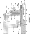
FIG. 3 is a schematic cross sectional view of an axial preload system, according to one or more embodiments; -
Fig. 4 is an enhanced schematic cross sectional view of the axial preload system ofFIG. 3 ; and -
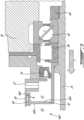
FIG. 5 is a schematic cross sectional view of an axial preload system, according to one or more embodiments. -
FIG. 1 illustrates agas turbine engine 10 of a type preferably provided for use in subsonic flight and configured for driving a rotatingcomponent 12, such as, but not limited to, a propeller or a helicopter rotor. Depending on the intended use, theengine 10 may be any suitable aircraft engine, and may be configured as a turbo propeller engine or a turboshaft engine. Thegas turbine engine 10 generally comprises in serial flow communication acompressor section 14 for pressurizing the air, acombustor 16 in which the compressed air is mixed with fuel and ignited for generating an annular stream of hot combustion gases, and aturbine section 18 for extracting energy from the combustion gases. - The exemplary embodiment shown in
FIG. 1 is a "reverse-flow" engine because gases flow from theinlet 17, at a rear portion of theengine 10, to theexhaust outlet 19, at a front portion of theengine 10. This is in contrast to "through-flow" gas turbine engines in which gases flow through the core of the engine from a front portion to a rear portion. Theengine 10 may be a reverse-flow engine (as illustrated) or a through-flow engine. - In the illustrated embodiment, the
turbine section 18 has a high-pressure turbine 18A in a driven engagement with a high-pressure compressor 14A. The high-pressure turbine 18A and the high-pressure compressor 14A are mounted on a high-pressure (HP)shaft 15. Theturbine 18 has a low-pressure turbine, also known aspower turbine 18B, configured to drive the rotatingcomponent 12. Thepower turbine 18B is configured to drive a low-pressure compressor 14b through a low pressure (LP)shaft 22. A reduction gearbox (RGB) 20 is configured to connect theLP shaft 22 that supports thepower turbine 18B to a shaft 24 (also referred to an RGB output shaft) that drivingly engages the rotatingcomponent 12, while providing a reduction speed ratio therebetween. - The
reduction gearbox 20 allows therotating component 12 to be driven at a given speed, which is different than the rotational speed of the low-pressure turbine 18B. Thereduction gearbox 20 allows both therotating component 12 and the low-pressure turbine 18B to rotate at their respective optimal speeds which are different. In the embodiment shown, thereduction gearbox 20 is axially mounted at the front end of theengine 10 and is disposed within ahousing 26 that circumferentially extends around a longitudinal axis L. Thehousing 26 is an external envelope of theturbo propeller engine 10. Accordingly, the rotation of the rotating component orpropeller 12 creates an airflow around thehousing 26 to create thrust. Thehousing 26 is thus wetted by air of an environment of theengine 10, i.e., ambient air. In a particular embodiment, thepropeller 12 comprises from two to eight blades equidistantly separated from one another. The length of each blade of thepropeller 12 may be substantially greater than a greatest radius of the housing 26-for example, at least double the size. Theshaft 24 is used to support therotating component 12, which generates a load on theshaft 24. The load has a radial component R and an axial component A relative to the axis L. The radial and axial components R and A of the load are the consequence of the creation of thrust by the rotation of therotating component 12. - Referring to
FIG. 2 , an exemplary reduction gearbox (RGB) 20 is shown, having anRGB input shaft 28 and theRGB output shaft 24. A bearinghousing 30 housing abearing shaft 32 is disposed adjacent theRGB 20, with thebearing shaft 32 rotatably coupling theRGB input shaft 28 to theLP shaft 22. A plurality of bearings, illustratively a roller bearing 34 and a ball bearing 36 operatively couple thebearing shaft 32 to the bearinghousing 30, provide support thereto. Additional bearings may be provided between theRGB 20 and therotating component 12, as will be discussed in further detail below. Acover 38 is provided at the junction of thebearing shaft 32 and theLP shaft 22, thecover 38 surrounding thebearing shaft 32 and operatively coupling the bearinghousing 30 to thebearing shaft 32. One ormore fasteners 40 may be provided for fastening thecover 38 to the bearinghousing 30. Theball bearing 36 and its associated components may herein be referred to as a ball bearing assembly. - The
ball bearing 36, also referred to as a thrust bearing, requires loading in an axial direction towards theRGB 20, for instance to prevent axial movement of the various shafts. As any amount of play between the bearing balls and the bearing races within the housing may exist, potentially causing issues such as noise and vibration of theengine 10, it may be desirable to preload theball bearing 36. As such, a system for preloading a ball bearing assembly may include apiston 42, also referred to as an air piston or a pneumatic piston, mounted to the bearingshaft 32 for rotation therewith and configured for exerting an axial preload, through the bearing shaft, against theball bearing 36. While the figures of the present disclosure depict aball bearing 36 being preloaded bypiston 42, it is understood the present disclosure is also applicable to other thrust bearings disposed in a bearing housing and extending about a rotating shaft in an aircraft engine. - Referring additionally to
FIGS. 3-4 , the shownpiston 42 is mounted to the bearingshaft 32, disposed radially within thecover 38, adjacent the junction between the bearingshaft 32 and theLP shaft 22. Other locations for thepiston 42 may be contemplated, as will be discussed in further detail below. Thepiston 42 is axially secured to the bearingshaft 32 and in sealing engagement with the bearinghousing 30 inside a piston chamber defined by the bearinghousing 30. Thepiston 42 divides the piston chamber into afirst cavity 44A and asecond cavity 44B. The shownpiston 42 has a firstaxial face 42A exposed to thefirst cavity 44A , and a secondaxial face 42B opposite the firstaxial face 42A and exposed to thesecond cavity 44B. Thesecond cavity 44B is axially disposed between theball bearing 36 and thepiston 42. Thesecond cavity 44B may extend between the secondaxial face 42B and theball bearing 36. Thepiston 42 extends radially towards thecover 38, with a sealingelement 46 disposed between thepiston 42 and thecover 38. The sealingelement 46 at least partially creates a seal between thefirst cavity 44A. Another sealingelement 46A is illustratively provided between thecover 38 and thepiston 42 at a radially inner end thereof. In the shown case, the sealingelements elements piston 42 and/or on the inner radius of thecover 38, with a seal clearance created therebetween. - A source of
compressed air 48 is fluidly coupled to thefirst cavity 44A, illustratively viaconduit 50 andinlet 52. In some embodiments, the source ofcompressed air 48 may be one of thecompressors first cavity 44A, and thus exert a first force against the firstaxial face 42A. The magnitude of the force may be controlled, for instance, by modulating the delivery of compressed air via inlet 52 (e.g., via a metering device upstream of the inlet 52), or by varying the degree of sealing provided by the sealingelements 46. 46A. In addition, the area of the first and second axial faces 42A, 42B may vary to vary the forces applied thereto, as these forces are a function of the pressure in thecavities first cavity 44A to thesecond cavity 44B via sealingelement 46. As such, air within thesecond cavity 44B at a second pressure P2 may exert a second force against thesecond piston face 42B, i.e., in a direction opposite the first force. The first force may be greater in magnitude than the second force, causing thepiston 42 to exert an axial force F, via the bearingshaft 32, against theball bearing 36, thereby preloading theball bearing 36. In the shown embodiment, the axial force F is represented by a "pushing" force towards theball bearing 36. - As discussed above, in the shown case, the sealing
element piston 42 and/or on the inner radius of thecover 38, with a seal clearance created therebetween. A leakage flow of pressurized air from thefirst cavity 44A to thesecond cavity 44B may thus be formed. This leakage flow may be used to create the necessary pressure differential between pressures P1, P2 to exert the desired axial force F along the bearingshaft 32. The number of fins, the geometry of the fins, and the magnitude of the seal clearance may vary to modulate the leakage flow. In some embodiments, one or more bleed holes 54 may be provided within or adjacent the seal clearance to further assist in modulating the pressure differential, with compressed air being bled to the ambient environment (at an ambient pressure Pamb) surrounding the bearinghousing 30. In the shown case, the sealingelement 46 includes two sets of fins, with an intermediate cavity disposed therebetween. Ableed hole 54 is disposed between the two sets of fins. As such, a leakage flow of pressurized air may flow from thefirst cavity 44A, through the sets of fins, to thesecond cavity 44B, to create a pressure differential for applying the force F on thepiston 42. As the pressure of air flowing across the sealingelement 46 is greater than the Pamb, some air may flow out of thebleed hole 54 to further create the required pressure differential. - As discussed above, a pressure differential between the two
cavities piston 42 and, through theshaft 32, against theball bearing 36. In the shown case, this pressure differential may be represented by the following equation:
bleed hole 54, and ΔPs2 being a pressure drop through the second set of fins. In addition, the resulting force acting against the firstaxial face 42A may be determined by multiplying the pressure P1 by a surface area of the firstaxial face 42A, while the resulting force acting against the secondaxial face 42B may be determined by multiplying the pressure P2 by a surface area of the secondaxial face 42B. The force F thus acting against thepiston 42, and thus against theball bearing 36, may be determined by subtracting the force acting against the secondaxial face 42B from the force acting against the firstaxial face 42A, with the force acting against the firstaxial face 42A being of greater magnitude than the force acting against the secondaxial face 42B. The preload force F being exerted on theball bearing 36 may thus be said to be a function of the pressure P1 in thefirst cavity 44A and the drops in pressure through the sealing element 46 (ΔPs1, ΔPs2, as well as bleed pressure differential ΔPbleed). -
FIGS. 2-4 show an exemplary clampedstack 56 also referred to as a stackup, along the bearingshaft 32 at thepiston 42. Theroller bearing 34, radially supporting the bearinghousing 30 via bearingsupport 58, is disposed against ashoulder 60 of the bearingshaft 32. Aspacer 62 mounted to the bearingshaft 32 is disposed axially between and abuts theroller bearing 34 and thepiston 42. A retainingnut 64 is mounted to the bearingshaft 32, axially adjacent to and abutting thepiston 42, for retaining the bearingshaft 32 to theLP shaft 22. Other stackup arrangements may be contemplated. In the shown case, asplined coupling 66 and a retainingnut 68 operatively couple the bearingshaft 32 to theRGB input shaft 28, although other arrangements may be contemplated. - In some embodiments, the
second cavity 44B may be at least partially filled with oil and may be fluidly coupled to anoil tank 70, illustratively viaconduit 72. The air pressure P2 in the oil tank may exceed a pressure inside theoil tank 70. As such, oil may be directed from thesecond cavity 44B towards theoil tank 70 viaconduit 72. In an exemplary embodiment, one or more oil nozzles may be provided within the bearinghousing 30, for instance directed towards thebearings housing 30 before being directed towards theoil tank 70. - Referring to
FIG. 5 , another embodiment of a system for preloading a ball bearing assembly is shown. Unless otherwise stated, like reference numbers refer to like elements, with apostrophes added to distinguish between locations relative to theRGB 20. Whereas the embodiment shown inFIGS. 2-4 depicts a ball bearing assembly axially disposed between theRGB 20 andLP shaft 22, the embodiment shown inFIG. 5 depicts a ball bearing assembly mounted to theRGB output shaft 24 and axially disposed between theRGB 20 and therotating component 12. As in the previous embodiment, compressed air from a compressed air source is introduced into thefirst cavity 44A' to exert a first force against the firstaxial face 42A'. Thesecond piston face 42B', with pressure P2' exerting a second force against thesecond piston face 42B' in a direction opposite the first force, may be disposed in asecond cavity 44B' exposed to ambient conditions (i.e., an open cavity) due to its location relative to therotating component 12. Sealing element 46' at least partially seals thefirst cavity 44A' from the ambient conditions in which thesecond piston face 42B' is located, while another sealing element, illustratively a plain seal 74', creates a seal between thefirst cavity 44A' and the bearings 36', 38'. In this embodiment, the pressure differential on opposing sides of the piston 42' exerts an overall axial force F', through theshaft 24, to preload the ball bearing 36', illustratively in a "pulling" direction. - In accordance with the present disclosure, there is taught a system for preloading a ball bearing assembly by way of a pneumatic piston exerting a preload force against a shaft. Advantageously, compressed air may be introduced to the cavities surrounding the piston before the engine is fully operational, thereby allowing the ball bearings to already be sufficiently preloaded before the various shafts begin rotating, which may allow for more precise axial preloading and an extended lifespan for the ball bearings. It is understood that a system for preloading a ball bearing assembly according to the present disclosure may include one or more ball bearing assemblies, for instance disposed on one or more sides of the
RGB 20, requiring preloading. - According to the present disclosure, there is taught an exemplary method for preloading a ball bearing mounted to a shaft in an aircraft engine. An axial load is exerted on the shaft towards the thrust bearing by applying air pressure from a source of compressed air onto a working face of a pneumatic piston axially securely mounted to the shaft.
- It is noted that various connections are set forth between elements in the preceding description and in the drawings. It is noted that these connections are general and, unless specified otherwise, may be direct or indirect and that this specification is not intended to be limiting in this respect. A coupling between two or more entities may refer to a direct connection or an indirect connection. An indirect connection may incorporate one or more intervening entities. The term "connected" or "coupled to" may therefore include both direct coupling (in which two elements that are coupled to each other contact each other) and indirect coupling (in which at least one additional element is located between the two elements).
- It is further noted that various method or process steps for embodiments of the present disclosure are described in the following description and drawings. The description may present the method and/or process steps as a particular sequence. However, to the extent that the method or process does not rely on the particular order of steps set forth herein, the method or process should not be limited to the particular sequence of steps described. As one of ordinary skill in the art would appreciate, other sequences of steps may be possible. Therefore, the particular order of the steps set forth in the description should not be construed as a limitation.
- As used herein, the terms "comprises", "comprising", or any other variation thereof, are intended to cover a non-exclusive inclusion, such that a process, method, article, or apparatus that comprises a list of elements does not include only those elements but may include other elements not expressly listed or inherent to such process, method, article, or apparatus.
- While various aspects of the present disclosure have been disclosed, it will be apparent to those of ordinary skill in the art that many more embodiments and implementations are possible within the scope of the present disclosure. For example, the present disclosure as described herein includes several aspects and embodiments that include particular features. Although these particular features may be described individually, it is within the scope of the present disclosure that some or all of these features may be combined with any one of the aspects and remain within the scope of the present disclosure. References to "various embodiments," "one embodiment," "an embodiment," "an example embodiment," etc., indicate that the embodiment described may include a particular feature, structure, or characteristic, but every embodiment may not necessarily include the particular feature, structure, or characteristic. Moreover, such phrases are not necessarily referring to the same embodiment. The use of the indefinite article "a" as used herein with reference to a particular element is intended to encompass "one or more" such elements, and similarly the use of the definite article "the" in reference to a particular element is not intended to exclude the possibility that multiple of such elements may be present.
- The embodiments described in this document provide non-limiting examples of possible implementations of the present technology. Upon review of the present disclosure, a person of ordinary skill in the art will recognize that changes may be made to the embodiments described herein without departing from the scope of the present technology. Yet further modifications could be implemented by a person of ordinary skill in the art in view of the present disclosure, which modifications would be within the scope of the present technology.
Claims (15)
- A system for preloading a thrust bearing assembly in an aircraft engine (10), the system comprising:a shaft (32) mounted for rotation about an axis;a thrust bearing (36) disposed in a bearing housing (30), the thrust bearing (36) operatively coupling the shaft (32) to the bearing housing (30);a piston (42) mounted to the shaft (32) inside a piston chamber, the piston (42) dividing the piston chamber into a first cavity (44A) and a second cavity (44B), the piston (42) having a first axial face (42A) facing the first cavity (44A) and a second axial face (42B) opposite the first axial face (42A), the second axial face (42B) facing the second cavity (44B) and the thrust bearing (36); anda source of compressed air (48) in fluid communication with the first cavity (44A) via a compressed air inlet (52), the compressed air (48) being at a first pressure (P1) exerting a first force along the axis against the first axial face (42A), the second cavity (44B) being at a second pressure (P2) exerting a second force against the second axial face (42B), the first force being greater than the second force, optionally wherein the source of compressed air (48) is provided from a bleed port of a compressor of the aircraft engine (10).
- The system as defined in claim 1, wherein the bearing housing (30) has a cover (38) surrounding the piston (42), and the system further comprises a sealing element (46) between the piston (42) and the cover (38), the sealing element (46) providing sealing between the first cavity (44A) and the second cavity (44B) of the piston chamber, and a bleed hole (54) defined in the cover (38), the bleed hole (54) fluidly coupled to the sealing element (46) and configured to bleed at least some of the compressed air (48) from the first cavity (44A).
- The system as defined in claim 2, wherein the sealing element (46) is one or more of a labyrinth seal, a brush seal, a carbon seal, an abrasive seal, and a plain seal.
- The system as defined in claim 2, wherein the sealing element (46) is a labyrinth seal having two sets of fins with an intermediate cavity disposed therebetween, the bleed hole (54) disposed between the two sets of fins and fluidly connected to the intermediate cavity.
- The system as defined in any preceding claim, further comprising a spacer (62) mounted to the shaft (32) and a roller bearing (34) mounted to the shaft (32) adjacent a shaft shoulder (60), the spacer (62) axially disposed and maintaining a stack-up between the piston (42) and the roller bearing (34), the piston (42) axially clamped between the spacer (62) and a retaining nut (64) threadedly engaged on the shaft (32).
- The system as defined in any preceding claim, wherein the thrust bearing (36) is a ball bearing.
- The system as defined in any preceding claim, wherein the second cavity (44B) is configured to be fluidly coupled to an oil tank (70) of the engine (10), the second pressure (P2) being higher than a pressure in the oil tank (70) to direct oil in the second cavity (44B) towards the oil tank (70).
- An aircraft engine (10), comprising:the system of any preceding claim;a rotating component (12); anda reduction gearbox (20) operatively connected to the rotating component (12), wherein the shaft (32) of the system is operatively coupled to the reduction gearbox (20), the bearing housing (30) extends around the shaft (32) and defines the piston chamber, and the piston (42) is axially secured to the shaft (32) and in sealing engagement with the bearing housing (30) inside the piston chamber.
- The aircraft engine (10) as defined in claim 8, further comprising a low pressure spool having a low pressure shaft (22) rotatably coupled to the shaft (32), and a reduction gearbox input shaft (28) rotatably coupling the shaft (32) to the reduction gearbox (20), the shaft (32) axially disposed between the low pressure shaft (22) and the reduction gearbox input shaft (28).
- The aircraft engine (10) as defined in claim 8 or 9, wherein the shaft (32) is axially disposed between the reduction gearbox (20) and the rotating component (12).
- The aircraft engine (10) as defined in any of claims 8 to 10, further comprising a or the oil tank (70) fluidly coupled to the second cavity (44B), the second pressure (P2) being higher than a pressure in the oil tank (70) to direct oil in the second cavity (44B) towards the oil tank (70).
- A method for preloading a thrust bearing (36) supporting a shaft (32) in an aircraft engine (10), the method comprising exerting an axial load on the shaft (32) towards the thrust bearing (36) by applying air pressure (P1) from a source of compressed air (48) onto a working face (42A) of a pneumatic piston (42) axially securely mounted to the shaft (32).
- The method as defined in claim 12, further comprising sealing a first cavity (44A) to which the working face (42A) is exposed from a second cavity (44B), separated from the first cavity (44A) by the pneumatic piston (42), via a sealing element (46).
- The method as defined in claim 13, further comprising bleeding air from the first cavity (44A) through a bleed hole (54) fluidly coupled to the sealing element (46).
- The method as defined in any of claims 12 to 14, wherein applying air pressure (P1) from the source of compressed air (48) includes directing bleed air from a compressor of the engine (10) to the first cavity (44A).
Applications Claiming Priority (1)
| Application Number | Priority Date | Filing Date | Title |
|---|---|---|---|
| US18/392,921 US12196132B1 (en) | 2023-12-21 | 2023-12-21 | System and method for preloading a bearing |
Publications (1)
| Publication Number | Publication Date |
|---|---|
| EP4575249A1 true EP4575249A1 (en) | 2025-06-25 |
Family
ID=94083246
Family Applications (1)
| Application Number | Title | Priority Date | Filing Date |
|---|---|---|---|
| EP24223087.8A Pending EP4575249A1 (en) | 2023-12-21 | 2024-12-23 | System and method for preloading a bearing |
Country Status (2)
| Country | Link |
|---|---|
| US (1) | US12196132B1 (en) |
| EP (1) | EP4575249A1 (en) |
Citations (4)
| Publication number | Priority date | Publication date | Assignee | Title |
|---|---|---|---|---|
| US4611934A (en) * | 1985-09-09 | 1986-09-16 | Cincinnati Milacron Inc. | Device for preloading bearings |
| USRE34310E (en) * | 1990-08-17 | 1993-07-13 | The Torrington Company | Variable preload bearing apparatus |
| US5862666A (en) * | 1996-12-23 | 1999-01-26 | Pratt & Whitney Canada Inc. | Turbine engine having improved thrust bearing load control |
| EP3536901B1 (en) * | 2018-03-07 | 2023-04-26 | General Electric Company | Bearing rotor thrust control |
Family Cites Families (6)
| Publication number | Priority date | Publication date | Assignee | Title |
|---|---|---|---|---|
| GB1484898A (en) * | 1974-09-11 | 1977-09-08 | Rolls Royce | Ducted fan gas turbine engine |
| US20070122265A1 (en) | 2005-11-30 | 2007-05-31 | General Electric Company | Rotor thrust balancing apparatus and method |
| US7694505B2 (en) * | 2006-07-31 | 2010-04-13 | General Electric Company | Gas turbine engine assembly and method of assembling same |
| GB0720628D0 (en) | 2007-10-20 | 2007-11-28 | Rolls Royce Plc | Bearing arrangement |
| US8182201B2 (en) | 2009-04-24 | 2012-05-22 | Pratt & Whitney Canada Corp. | Load distribution system for gas turbine engine |
| US8584514B2 (en) | 2010-05-18 | 2013-11-19 | Dresser-Rand Company | Axial loading device and method for magnetically-supported rotor systems |
-
2023
- 2023-12-21 US US18/392,921 patent/US12196132B1/en active Active
-
2024
- 2024-12-23 EP EP24223087.8A patent/EP4575249A1/en active Pending
Patent Citations (4)
| Publication number | Priority date | Publication date | Assignee | Title |
|---|---|---|---|---|
| US4611934A (en) * | 1985-09-09 | 1986-09-16 | Cincinnati Milacron Inc. | Device for preloading bearings |
| USRE34310E (en) * | 1990-08-17 | 1993-07-13 | The Torrington Company | Variable preload bearing apparatus |
| US5862666A (en) * | 1996-12-23 | 1999-01-26 | Pratt & Whitney Canada Inc. | Turbine engine having improved thrust bearing load control |
| EP3536901B1 (en) * | 2018-03-07 | 2023-04-26 | General Electric Company | Bearing rotor thrust control |
Also Published As
| Publication number | Publication date |
|---|---|
| US12196132B1 (en) | 2025-01-14 |
Similar Documents
| Publication | Publication Date | Title |
|---|---|---|
| EP3557028B1 (en) | Gas turbine engine | |
| US11215078B2 (en) | Gas turbine engine | |
| CN110878760B (en) | Seal components for turbomachinery | |
| CN109477389B (en) | System and method for seals of inboard exhaust circuits in turbines | |
| EP3232011A1 (en) | Hydrodynamic carbon face seal pressure booster | |
| US10612436B2 (en) | Deoiler for a gas turbine engine | |
| EP3396119B1 (en) | Intershaft compartment buffering arrangement | |
| EP3636971A1 (en) | A valve assembly | |
| US20200191276A1 (en) | Device with two structural components and gas turbine engine | |
| US20220389873A1 (en) | Gearbox and gas turbine propulsion unit | |
| US11506082B2 (en) | Oil scavenge system | |
| US10995676B2 (en) | Planetary gear device, gas turbine engine and method for manufacturing a planetary gear device | |
| US12196132B1 (en) | System and method for preloading a bearing | |
| EP3901424A1 (en) | Gas turbine engine lubrication system | |
| EP3712394A1 (en) | A gas turbine bearing support structure | |
| US20220099175A1 (en) | Sealing system, gear box with sealing system and a gas turbine engine with sealing system | |
| EP3783213B1 (en) | Gas turbine engine | |
| US12516668B2 (en) | Gear pump assembly | |
| US12560100B1 (en) | Double directionally pre-loaded damped ball bearing | |
| US11933295B2 (en) | Tapered shafts for fluid pumps | |
| EP3663542B1 (en) | Oil supply arrangement for bearing | |
| US20250257770A1 (en) | Gearbox assembly having a gear brake system | |
| US20200182151A1 (en) | Oil supply arrangement for bearing | |
| GB2588956A (en) | A variable vane assembly |
Legal Events
| Date | Code | Title | Description |
|---|---|---|---|
| PUAI | Public reference made under article 153(3) epc to a published international application that has entered the european phase |
Free format text: ORIGINAL CODE: 0009012 |
|
| STAA | Information on the status of an ep patent application or granted ep patent |
Free format text: STATUS: THE APPLICATION HAS BEEN PUBLISHED |
|
| AK | Designated contracting states |
Kind code of ref document: A1 Designated state(s): AL AT BE BG CH CY CZ DE DK EE ES FI FR GB GR HR HU IE IS IT LI LT LU LV MC ME MK MT NL NO PL PT RO RS SE SI SK SM TR |
|
| STAA | Information on the status of an ep patent application or granted ep patent |
Free format text: STATUS: REQUEST FOR EXAMINATION WAS MADE |
|
| 17P | Request for examination filed |
Effective date: 20251224 |