EP4575234A1 - Ejector and refrigeration system - Google Patents
Ejector and refrigeration system Download PDFInfo
- Publication number
- EP4575234A1 EP4575234A1 EP24221267.8A EP24221267A EP4575234A1 EP 4575234 A1 EP4575234 A1 EP 4575234A1 EP 24221267 A EP24221267 A EP 24221267A EP 4575234 A1 EP4575234 A1 EP 4575234A1
- Authority
- EP
- European Patent Office
- Prior art keywords
- magnet
- housing
- ring
- nozzle
- inner ring
- Prior art date
- Legal status (The legal status is an assumption and is not a legal conclusion. Google has not performed a legal analysis and makes no representation as to the accuracy of the status listed.)
- Pending
Links
Images


Classifications
-
- F—MECHANICAL ENGINEERING; LIGHTING; HEATING; WEAPONS; BLASTING
- F04—POSITIVE - DISPLACEMENT MACHINES FOR LIQUIDS; PUMPS FOR LIQUIDS OR ELASTIC FLUIDS
- F04F—PUMPING OF FLUID BY DIRECT CONTACT OF ANOTHER FLUID OR BY USING INERTIA OF FLUID TO BE PUMPED; SIPHONS
- F04F5/00—Jet pumps, i.e. devices in which flow is induced by pressure drop caused by velocity of another fluid flow
- F04F5/02—Jet pumps, i.e. devices in which flow is induced by pressure drop caused by velocity of another fluid flow the inducing fluid being liquid
- F04F5/04—Jet pumps, i.e. devices in which flow is induced by pressure drop caused by velocity of another fluid flow the inducing fluid being liquid displacing elastic fluids
-
- F—MECHANICAL ENGINEERING; LIGHTING; HEATING; WEAPONS; BLASTING
- F04—POSITIVE - DISPLACEMENT MACHINES FOR LIQUIDS; PUMPS FOR LIQUIDS OR ELASTIC FLUIDS
- F04F—PUMPING OF FLUID BY DIRECT CONTACT OF ANOTHER FLUID OR BY USING INERTIA OF FLUID TO BE PUMPED; SIPHONS
- F04F5/00—Jet pumps, i.e. devices in which flow is induced by pressure drop caused by velocity of another fluid flow
- F04F5/02—Jet pumps, i.e. devices in which flow is induced by pressure drop caused by velocity of another fluid flow the inducing fluid being liquid
- F04F5/10—Jet pumps, i.e. devices in which flow is induced by pressure drop caused by velocity of another fluid flow the inducing fluid being liquid displacing liquids, e.g. containing solids, or liquids and elastic fluids
-
- F—MECHANICAL ENGINEERING; LIGHTING; HEATING; WEAPONS; BLASTING
- F04—POSITIVE - DISPLACEMENT MACHINES FOR LIQUIDS; PUMPS FOR LIQUIDS OR ELASTIC FLUIDS
- F04F—PUMPING OF FLUID BY DIRECT CONTACT OF ANOTHER FLUID OR BY USING INERTIA OF FLUID TO BE PUMPED; SIPHONS
- F04F5/00—Jet pumps, i.e. devices in which flow is induced by pressure drop caused by velocity of another fluid flow
- F04F5/14—Jet pumps, i.e. devices in which flow is induced by pressure drop caused by velocity of another fluid flow the inducing fluid being elastic fluid
- F04F5/24—Jet pumps, i.e. devices in which flow is induced by pressure drop caused by velocity of another fluid flow the inducing fluid being elastic fluid displacing liquids, e.g. containing solids, or liquids and elastic fluids
-
- F—MECHANICAL ENGINEERING; LIGHTING; HEATING; WEAPONS; BLASTING
- F04—POSITIVE - DISPLACEMENT MACHINES FOR LIQUIDS; PUMPS FOR LIQUIDS OR ELASTIC FLUIDS
- F04F—PUMPING OF FLUID BY DIRECT CONTACT OF ANOTHER FLUID OR BY USING INERTIA OF FLUID TO BE PUMPED; SIPHONS
- F04F5/00—Jet pumps, i.e. devices in which flow is induced by pressure drop caused by velocity of another fluid flow
- F04F5/44—Component parts, details, or accessories not provided for in, or of interest apart from, groups F04F5/02 - F04F5/42
-
- F—MECHANICAL ENGINEERING; LIGHTING; HEATING; WEAPONS; BLASTING
- F04—POSITIVE - DISPLACEMENT MACHINES FOR LIQUIDS; PUMPS FOR LIQUIDS OR ELASTIC FLUIDS
- F04F—PUMPING OF FLUID BY DIRECT CONTACT OF ANOTHER FLUID OR BY USING INERTIA OF FLUID TO BE PUMPED; SIPHONS
- F04F5/00—Jet pumps, i.e. devices in which flow is induced by pressure drop caused by velocity of another fluid flow
- F04F5/44—Component parts, details, or accessories not provided for in, or of interest apart from, groups F04F5/02 - F04F5/42
- F04F5/46—Arrangements of nozzles
- F04F5/461—Adjustable nozzles
-
- F—MECHANICAL ENGINEERING; LIGHTING; HEATING; WEAPONS; BLASTING
- F04—POSITIVE - DISPLACEMENT MACHINES FOR LIQUIDS; PUMPS FOR LIQUIDS OR ELASTIC FLUIDS
- F04F—PUMPING OF FLUID BY DIRECT CONTACT OF ANOTHER FLUID OR BY USING INERTIA OF FLUID TO BE PUMPED; SIPHONS
- F04F5/00—Jet pumps, i.e. devices in which flow is induced by pressure drop caused by velocity of another fluid flow
- F04F5/44—Component parts, details, or accessories not provided for in, or of interest apart from, groups F04F5/02 - F04F5/42
- F04F5/46—Arrangements of nozzles
- F04F5/463—Arrangements of nozzles with provisions for mixing
-
- F—MECHANICAL ENGINEERING; LIGHTING; HEATING; WEAPONS; BLASTING
- F04—POSITIVE - DISPLACEMENT MACHINES FOR LIQUIDS; PUMPS FOR LIQUIDS OR ELASTIC FLUIDS
- F04F—PUMPING OF FLUID BY DIRECT CONTACT OF ANOTHER FLUID OR BY USING INERTIA OF FLUID TO BE PUMPED; SIPHONS
- F04F5/00—Jet pumps, i.e. devices in which flow is induced by pressure drop caused by velocity of another fluid flow
- F04F5/44—Component parts, details, or accessories not provided for in, or of interest apart from, groups F04F5/02 - F04F5/42
- F04F5/48—Control
-
- F—MECHANICAL ENGINEERING; LIGHTING; HEATING; WEAPONS; BLASTING
- F25—REFRIGERATION OR COOLING; COMBINED HEATING AND REFRIGERATION SYSTEMS; HEAT PUMP SYSTEMS; MANUFACTURE OR STORAGE OF ICE; LIQUEFACTION SOLIDIFICATION OF GASES
- F25B—REFRIGERATION MACHINES, PLANTS OR SYSTEMS; COMBINED HEATING AND REFRIGERATION SYSTEMS; HEAT PUMP SYSTEMS
- F25B41/00—Fluid-circulation arrangements
-
- F—MECHANICAL ENGINEERING; LIGHTING; HEATING; WEAPONS; BLASTING
- F25—REFRIGERATION OR COOLING; COMBINED HEATING AND REFRIGERATION SYSTEMS; HEAT PUMP SYSTEMS; MANUFACTURE OR STORAGE OF ICE; LIQUEFACTION SOLIDIFICATION OF GASES
- F25B—REFRIGERATION MACHINES, PLANTS OR SYSTEMS; COMBINED HEATING AND REFRIGERATION SYSTEMS; HEAT PUMP SYSTEMS
- F25B9/00—Compression machines, plants or systems, in which the refrigerant is air or other gas of low boiling point
- F25B9/08—Compression machines, plants or systems, in which the refrigerant is air or other gas of low boiling point using ejectors
-
- F—MECHANICAL ENGINEERING; LIGHTING; HEATING; WEAPONS; BLASTING
- F25—REFRIGERATION OR COOLING; COMBINED HEATING AND REFRIGERATION SYSTEMS; HEAT PUMP SYSTEMS; MANUFACTURE OR STORAGE OF ICE; LIQUEFACTION SOLIDIFICATION OF GASES
- F25B—REFRIGERATION MACHINES, PLANTS OR SYSTEMS; COMBINED HEATING AND REFRIGERATION SYSTEMS; HEAT PUMP SYSTEMS
- F25B2341/00—Details of ejectors not being used as compression device; Details of flow restrictors or expansion valves
- F25B2341/001—Ejectors not being used as compression device
- F25B2341/0012—Ejectors with the cooled primary flow at high pressure
-
- F—MECHANICAL ENGINEERING; LIGHTING; HEATING; WEAPONS; BLASTING
- F25—REFRIGERATION OR COOLING; COMBINED HEATING AND REFRIGERATION SYSTEMS; HEAT PUMP SYSTEMS; MANUFACTURE OR STORAGE OF ICE; LIQUEFACTION SOLIDIFICATION OF GASES
- F25B—REFRIGERATION MACHINES, PLANTS OR SYSTEMS; COMBINED HEATING AND REFRIGERATION SYSTEMS; HEAT PUMP SYSTEMS
- F25B2341/00—Details of ejectors not being used as compression device; Details of flow restrictors or expansion valves
- F25B2341/001—Ejectors not being used as compression device
- F25B2341/0013—Ejector control arrangements
Definitions
- the present invention relates to a field of refrigeration equipment, and in particular, to an ejector and a refrigeration system using the ejector.
- An ejector (also called an ejection device) is a component that increases a pressure of an ejected fluid without consuming electrical or mechanical energy. Since the ejector has a small volume, a light weight, a compact structure, and high efficiency, it has gradually become an indispensable component in a refrigeration or heating system.
- a nozzle is a main component of the ejector, and a flow rate of a refrigerant ejected by the nozzle is very important for an effect of the refrigeration or heating system.
- the flow rate of the refrigerant at a nozzle outlet can be changed by changing a cross-sectional area of the nozzle outlet, thereby adapting to needs of the changing operating conditions.
- this requires an addition of an electric drive mechanism, resulting in an increase in the volume of the ejector.
- the present invention provides an ejector and a refrigeration system for solving or alleviating some problems existing in the related art.
- a first aspect of the present invention provides an ejector.
- the ejector includes:
- the ejector further includes: an adapter detachably connected to an end of the housing opposite to the discharge port, the adapter including a first cylindrical extension, the first outer ring being sleeved outside the first cylindrical extension, and the first inner ring being sleeved inside the first cylindrical extension; and an end cap detachably fixed to the first cylindrical extension.
- a connection between the first cylindrical extension and the end cap is filled with a sealant.
- a cross section of the second end of the needle valve is non-circular.
- a transition section is provided between the second end of the needle valve and the threaded section, and a cross-sectional dimension of the transition section is larger than that of the threaded section and the second end.
- the ejector further includes: a second retainer fixed in the nozzle and located on a side of the first retainer close to the nozzle outlet, in which a center of the second retainer is provided with a second retainer through hole through which the needle valve passes.
- an outer periphery of the hollow body includes a first abutment portion and a second abutment portion both abutting against an inner wall of the housing, the first abutment portion is located on a side of the second abutment portion close to the discharge port, a portion of the hollow body between the first abutment portion and the second abutment portion is a first chamber, the first chamber is in communication with the first suction port, and an outer periphery of the first chamber is provided with a hollow portion.
- the nozzle outlet is formed as a nozzle outer wall converging section having a reduced diameter
- the inner wall of the housing is provided with a housing inner wall converging section matched with the nozzle outer wall converging section
- the housing further includes a second suction port
- a second chamber that is in communication with the second suction port is formed between the first abutment portion and the housing inner wall converging section.
- a narrower diameter end of the housing inner wall converging section is a refrigerant mixture inlet
- the inner wall of the housing further includes an equal-diameter section and a diverging section, and the equal-diameter section and the diverging section, which are sequentially provided along a flow direction of a refrigerant mixture, allow the refrigerant mixture inlet and the discharge port to communicate with each other, and the nozzle is movable in the axial direction to adjust an opening degree of the refrigerant mixture inlet.
- the ejector further includes: a second magnetic rotation mechanism including a second outer ring and a second inner ring coaxially disposed on an inner side of the second outer ring, in which an inner surface of the second outer ring and an outer surface of the second inner ring are spaced from and opposed to each other and correspondingly provided with a plurality of groups of magnets having opposite magnetic properties respectively, and the inner surface of the second inner ring is in threaded connection with an outer surface of the nozzle.
- a second magnetic rotation mechanism including a second outer ring and a second inner ring coaxially disposed on an inner side of the second outer ring, in which an inner surface of the second outer ring and an outer surface of the second inner ring are spaced from and opposed to each other and correspondingly provided with a plurality of groups of magnets having opposite magnetic properties respectively, and the inner surface of the second inner ring is in threaded connection with an outer surface of the nozzle.
- an end of the housing opposite to the discharge port is provided with a second cylindrical extension, the second outer ring is sleeved outside the second cylindrical extension, and the second inner ring is sleeved inside the second cylindrical extension, and the adapter is in threaded connection with the second cylindrical extension, and the threaded connection is filled with a sealant.
- the ejector further includes: a guide mechanism provided between the housing and the nozzle and configured to limit circumferential rotation of the nozzle relative to the housing.
- the guide mechanism further includes:
- the inner surface of the first outer ring is provided with a first magnet and a second magnet, the first magnet and the second magnet are sequentially and alternately connected, magnetism of the first magnet is opposite to magnetism of the second magnet, and the number of the first magnet and the number of the second magnet are the same and are respectively at least two, and the outer surface of the first inner ring is provided with a third magnet and a fourth magnet, the third magnet and the fourth magnet are sequentially and alternately connected, magnetism of the third magnet is opposite to magnetism of the fourth magnet, and the number of the third magnet and the number of the fourth magnet are the same and are respectively at least two.
- the first magnet and the second magnet are fixed on the inner surface of the first outer ring by bonding, riveting, or threaded connection
- the third magnet and the fourth magnet are fixed on the outer surface of the first inner ring by bonding, riveting, or threaded connection.
- the first magnet and the second magnet are the same in size and shape
- the third magnet and the fourth magnet are the same in size and shape
- two sides of the first outer ring are respectively provided with a first retaining ring, and the first retaining ring includes
- an outer surface of the first outer ring is provided with a gear, and the first outer ring is in transmission connection with an external motor through the gear.
- a second aspect of the present invention provides a refrigeration system.
- the refrigeration system is provided with the foregoing ejector.
- an ejector uses the Venturi effect to increase a pressure energy of a fluid at a suction port of the ejector by a motive fluid supplied to a motive port of the ejector.
- the ejector can be arranged in a refrigeration system to cause the refrigerant to do work.
- the ejector is configured to eject a low-pressure refrigerant from an evaporator using a high-pressure refrigerant from a condenser and mix them into a medium-pressure gas-liquid two-phase refrigerant.
- an embodiment of the present invention provides an ejector.
- the ejector includes a housing 1, a nozzle 2, a first retainer 3, a needle valve 4, and a first magnetic rotation mechanism 5.
- the housing 1 includes a first suction port 11 and a discharge port 12, and the discharge port 12 is located at one end of the housing 1 in an axial direction.
- the nozzle 2 is provided in the housing 1, and the nozzle 2 includes a hollow body 21 and a nozzle outlet 22, an interior of the hollow body 21 is in communication with the first suction port 11, and the nozzle outlet 22 is in communication with the discharge port 12.
- the first magnetic rotation mechanism 5 includes a first outer ring 51 and a first inner ring 52 coaxially disposed on an inner side of the first outer ring 51, an inner surface of the first outer ring 51 and an outer surface of the first inner ring 52 are spaced from and opposite to each other, and correspondingly provided with a plurality of groups of magnets having opposite magnetic properties respectively (a first magnet 511, a second magnet 512, a third magnet 522, and a fourth magnet 523), a center of the first inner ring 52 is provided with an inner ring through hole 521, and the second end of the needle valve 4 is matched with and passes through the inner ring through hole 521 in a manner that allows sliding in the axial direction and torque transmission.
- the first magnetic rotation mechanism 5 is provided in a circumferential direction of the housing 1, which reduces a volume of the housing 1 in the axial direction, and achieves rotation and movement of the needle valve 4 inside the housing 1 through non-contact transmission torque of the magnets on the first outer ring 51 and the first inner ring 52, which simplifies a drive structure of the needle valve 4 and reduces a processing difficulty of the ejector.
- the ejector further includes an adapter 13 and an end cap 14.
- the adapter 13 is detachably connected to an end of the housing 1 opposite to the discharge port 12, the adapter 13 includes a first cylindrical extension 131, the first outer ring 51 is sleeved outside the first cylindrical extension 131, and the first inner ring 52 is sleeved inside the first cylindrical extension 131.
- the end cap 14 is detachably fixed to the first cylindrical extension 131. In this way, providing the adapter 13 and the end cap 14 improves mounting flexibility of the ejector and the first magnetic rotation mechanism 5, and can facilitate maintenance and replacement.
- the end cap 14 is threadably connected to the first cylindrical extension 131.
- a connection between the first cylindrical extension 131 and the end cap 14 is filled with a sealant.
- the sealant is provided to prevent a high-pressure fluid or a low-pressure fluid in the ejector from leaking from the connection between the first cylindrical extension 131 and the end cap 14.
- a cross section of the second end 42 of the needle valve 4 is non-circular.
- the cross section of the second end 42 of the needle valve 4 is a rectangle, a square, a triangle, a parallelogram, or the like.
- a transition section 44 is provided between the second end 42 of the needle valve 4 and the threaded section 43, and a cross-sectional dimension of the transition section 44 is greater than that of the threaded section 43 and the second end 42.
- a movement distance of the needle valve 4 in the axial direction can be defined as a predetermined length.
- the dimension of the transition section 44 is larger than a dimension of the threaded section 43, so that the threaded section 43 is blocked by the transition section 44 after rotating a specified pitch, and cannot further move toward the nozzle outlet 22.
- cross-sectional dimension may be a cross-sectional area, a cross-sectional perimeter, or a side length. As long as a part of the transition section 44 cannot pass through the threaded hole or the inner ring through hole 521, it is considered that the cross-sectional dimension of the transition section 44 is greater than that of the threaded section 43 and the second end 42.
- the ejector further includes a second retainer 6 fixed in the nozzle 2 and located on a side of the first retainer 3 close to the nozzle outlet 22.
- a center of the second retainer 6 is provided with a second retainer through hole 61 through which the needle valve 4 passes.
- Providing the second retainer 6 can provide support for movement of the needle valve 4 in the axial direction, ensure stability of the needle valve 4 during the movement in the axial direction, and prevent radial deviation of the needle valve 4 during the movement in the axial direction.
- a pin 62 is further included, which correspondingly connects the second retainer 6 and the hollow body 21 of the nozzle 2, to fix the second retainer 6 to the hollow body 21.
- an outer periphery of the hollow body 21 includes a first abutment portion 211 and a second abutment portion 212 both abutting against the inner wall of the housing 1.
- the first abutment portion 211 is located on a side of the second abutment portion 212 close to the discharge port 12.
- a portion of the hollow body 21 between the first abutment portion 211 and the second abutment portion 212 is a first chamber 213, the first chamber 213 is in communication with the first suction port 11, and an outer periphery of the first chamber 213 is circumferentially provided with hollow portions 214.
- diameters of the first abutment portion 211 and the second abutment portion 212 are greater than a diameter of the first chamber 213, so that there is a flow-through space between the first chamber 213 and an inner wall of the housing 1, and a fluid entering from the first suction port 11 enters the first chamber 213 of the nozzle 2 through the flow-through space and the hollow portion 214.
- Four hollow portions 214 are evenly provided in a circumferential direction of the hollow body 21.
- the nozzle outlet 22 is formed as a nozzle outer wall converging section 215 having a reduced diameter.
- the inner wall of the housing 1 is provided with a housing inner wall converging section 15 matched with the nozzle outer wall converging section 215.
- the housing 1 further includes a second suction port 16, and a second chamber 19 that is in communication with the second suction port 16 is formed between the first abutment portion 211 and the housing inner wall converging section 15.
- providing the first abutment portion 211 can prevent the fluid sucked in by the second suction port 16 from entering the first chamber 213 in advance to be mixed with the fluid in the first chamber 213, and the fluid at the outlet of the first chamber 213 enters the second chamber 19 and is mixed with the fluid sucked in by the second suction port 16 to transfer energy and momentum.
- a narrower diameter end of the housing inner wall converging section 15 is a refrigerant mixture inlet 151.
- the inner wall of the housing 1 further includes an equal-diameter section 17 and a diverging section 18, the equal-diameter section 17 and the diverging section 18, that are sequentially provided along a flow direction of a refrigerant mixture, allow the refrigerant mixture inlet 151 and the discharge port 12 to communicate with each other, and the nozzle 2 is movable in the axial direction to adjust an opening degree of the refrigerant mixture inlet 151.
- first inner ring 52 two sides of the first inner ring 52 are respectively provided with a second retaining ring 92, and the second retaining ring 92 includes a second annular body 921 and a plurality of second balls 922.
- the second annular body 921 is provided between the first inner ring 52 and the housing 1.
- the plurality of second balls 922 are rotatably provided in the second annular body 921, and a second ball ring groove 9221 for accommodating the second ball 922 is correspondingly formed between the first inner ring 52 and the housing 1.
- FIGS. 15 and 16 are schematic diagrams of distribution of first ball ring grooves 9121 on left and right sides of the adapter 13 (left and right sides based on the axial direction of the ejector).
- the first ball ring groove 9121 is used to provide a rotation space of the plurality of balls at corresponding positions.
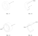
- FIGS. 17 and 18 are schematic diagrams of distribution of the second ball ring grooves 9221 in the housing 1 on a left side of the first inner ring 52 (as at A portion in FIG. 4 ).
- FIG. 19 and FIG. 20 are schematic diagrams of distribution of the second ball ring groove 9221 in the housing 1 on a right side of the first inner ring 52 (as at B portion in FIG. 4 ).
- two sides of the second outer ring 71 are respectively provided with a third retaining ring 93, and two sides of the second inner ring 72 are respectively provided with a fourth retaining ring 94, so that the second outer ring 71 and the second inner ring 72 are prevented from moving in the axial direction, and meanwhile, the second outer ring 71 and the second inner ring 72 are constrained in the radial direction, and therefore the second outer ring 71 and the second inner ring 72 can only rotate around their axes.
- structures of the first retaining ring 91, the second retaining ring 92, the third retaining ring 93, and the fourth retaining ring 94 are the same, and all include an annular body and a plurality of balls (for example, a third ball 931 and a fourth ball 941) rotatably provided in the annular body.
- FIGS. 4 and 12 illustrate schematic diagrams of distribution of a third ball ring groove 932 corresponding to the third ball 931 in the third retaining ring 93 on a right side of the second outer ring 71, and distribution of a fourth ball ring groove 942 corresponding to the fourth ball 941 in the fourth retaining ring 94 on a right side of the second inner ring 72, in the housing 1.
- the third ball 931 in the third retaining ring 93 on a left side of the second outer ring 71 is correspondingly and rotatably provided in the first ball ring groove 9121 on the right side of the adapter 13
- the fourth ball 941 in the fourth retaining ring 94 on a left side of the second inner ring 72 is correspondingly and rotatably disposed in the second ball ring groove 9221 of the housing 1 (at B portion in FIG. 4 ).
- cross sections of the first ball ring groove 9121, the second ball ring groove 9221, the third ball ring groove 932, and the fourth ball ring groove 942 are all semicircular.
- the first outer ring 51, the first inner ring 52, the second outer ring 71, and the second inner ring 72 are each formed with an annular groove that matches and engages with the ball ring groove at positions corresponding to rolling of the balls (such as the first outer ring 51 having first annular grooves 514 on both sides, and the first inner ring 52 having second annular grooves 524 on both sides).
- a cross section of the annular groove is semicircular, and the annular groove engages with the corresponding ball ring groove to form a rotating space having a circular cross section, allowing the balls to be rotatably provided.
- an outer surface of the first outer ring 51 is provided with a first gear 513, and the first outer ring 51 is in transmission connection with a first external motor 53 through the first gear 513.
- an outer surface of the second outer ring 71 is provided with a second gear 711, and the second outer ring 71 is in transmission connection with a second external motor 74 through the second gear 711.
- the ejector according to the present invention has a simple structure, low cost, and high reliability, and the refrigerant flow rate at the nozzle outlet 22 is changed by adjusting the position of the nozzle and/or the needle valve, thereby adapting to different working conditions and ensuring the stability of the system.
- the present invention further provides a refrigeration system provided with the above ejector.
- the refrigeration system includes a compressor, a condenser, an evaporator, a throttling device, a gas-liquid separator, and the like connected by pipelines.
- the first suction port 11 of the ejector is in communication with the condenser
- the second suction port 16 of the ejector is in communication with the evaporator
- the discharge port 12 of the ejector is in communication with the gas-liquid separator.
- the above ejector can meet the requirements of the compressor under various pressure conditions, and further reduce the power consumption of the compressor, thereby improving the operation efficiency of the entire refrigeration system. Therefore, the ejector according to the present invention is suitable for popularization and disclosure to various refrigeration systems.
Landscapes
- Engineering & Computer Science (AREA)
- Physics & Mathematics (AREA)
- Mechanical Engineering (AREA)
- General Engineering & Computer Science (AREA)
- Fluid Mechanics (AREA)
- Thermal Sciences (AREA)
- Jet Pumps And Other Pumps (AREA)
Abstract
The present invention provides an ejector and a refrigeration system. The ejector includes: a housing (1); a nozzle (2); a first retainer (3) fixed in the nozzle (2), a center of which being provided with a first retainer through hole (31); a needle valve (4) that is provided in the nozzle (2) and includes a first end (41), a second end (42), and a threaded section (43), the threaded section (43) being engaged with the first retainer through hole (31), and the first end (41) being movable to adjust an opening degree of the nozzle outlet (22); and a first magnetic rotation mechanism (5) including a first outer ring (51) and a first inner ring (52), an inner surface of the first outer ring (51) and an outer surface of the first inner ring (52) being spaced from and opposed to each other and correspondingly provided with a plurality of groups of magnets (511, 512, 522, 523) having opposite magnetic properties respectively, a center of the first inner ring (52) being provided with an inner ring through hole (521), and the second end (42) of the needle valve (4) being matched with and passing through the inner ring through hole (521). A nozzle outlet (22) flow rate adjusting and driving mechanism according to the present invention is simple in structure, easy to manufacture, and high in flexibility.
Description
- The present invention relates to a field of refrigeration equipment, and in particular, to an ejector and a refrigeration system using the ejector.
- An ejector (also called an ejection device) is a component that increases a pressure of an ejected fluid without consuming electrical or mechanical energy. Since the ejector has a small volume, a light weight, a compact structure, and high efficiency, it has gradually become an indispensable component in a refrigeration or heating system.
- A nozzle is a main component of the ejector, and a flow rate of a refrigerant ejected by the nozzle is very important for an effect of the refrigeration or heating system. When system operating conditions are changed, the flow rate of the refrigerant at a nozzle outlet can be changed by changing a cross-sectional area of the nozzle outlet, thereby adapting to needs of the changing operating conditions. However, this requires an addition of an electric drive mechanism, resulting in an increase in the volume of the ejector.
- In view of the above problems, the present invention provides an ejector and a refrigeration system for solving or alleviating some problems existing in the related art.
- A first aspect of the present invention provides an ejector. The ejector includes:
- a housing including a first suction port and a discharge port, the discharge port being located at one end of the housing in an axial direction;
- a nozzle that is provided in the housing and includes a hollow body and a nozzle outlet, an interior of the hollow body being in communication with the first suction port, and the nozzle outlet being in communication with the discharge port;
- a first retainer fixed in the nozzle, a center of which being formed with a first retainer through hole;
- a needle valve including a first end, a second end, and a threaded section between the first end and the second end, the threaded section being engaged with the first retainer through hole, and the first end being movable between a position away from the nozzle outlet and a position abutting against the nozzle outlet to adjust an opening degree of the nozzle outlet; and
- a first magnetic rotation mechanism including a first outer ring and a first inner ring coaxially disposed on an inner side of the first outer ring, an inner surface of the first outer ring and an outer surface of the first inner ring being spaced from and opposed to each other and correspondingly provided with a plurality of groups of magnets having opposite magnetic properties respectively, a center of the first inner ring being provided with an inner ring through hole, and the second end of the needle valve being matched with and passing through the inner ring through hole in a manner that allows sliding in the axial direction and torque transmission.
- In an optional technical solution, the ejector further includes: an adapter detachably connected to an end of the housing opposite to the discharge port, the adapter including a first cylindrical extension, the first outer ring being sleeved outside the first cylindrical extension, and the first inner ring being sleeved inside the first cylindrical extension; and an end cap detachably fixed to the first cylindrical extension.
- In an optional technical solution, a connection between the first cylindrical extension and the end cap is filled with a sealant.
- In an optional technical solution, a cross section of the second end of the needle valve is non-circular.
- In an optional technical solution, a transition section is provided between the second end of the needle valve and the threaded section, and a cross-sectional dimension of the transition section is larger than that of the threaded section and the second end.
- In an optional technical solution, the ejector further includes: a second retainer fixed in the nozzle and located on a side of the first retainer close to the nozzle outlet, in which a center of the second retainer is provided with a second retainer through hole through which the needle valve passes.
- In an optional technical solution, an outer periphery of the hollow body includes a first abutment portion and a second abutment portion both abutting against an inner wall of the housing, the first abutment portion is located on a side of the second abutment portion close to the discharge port, a portion of the hollow body between the first abutment portion and the second abutment portion is a first chamber, the first chamber is in communication with the first suction port, and an outer periphery of the first chamber is provided with a hollow portion.
- In an optional technical solution, in a direction close to the discharge port along the axial direction, the nozzle outlet is formed as a nozzle outer wall converging section having a reduced diameter, the inner wall of the housing is provided with a housing inner wall converging section matched with the nozzle outer wall converging section, and the housing further includes a second suction port, and a second chamber that is in communication with the second suction port is formed between the first abutment portion and the housing inner wall converging section.
- In an optional technical solution, a narrower diameter end of the housing inner wall converging section is a refrigerant mixture inlet, and
the inner wall of the housing further includes an equal-diameter section and a diverging section, and the equal-diameter section and the diverging section, which are sequentially provided along a flow direction of a refrigerant mixture, allow the refrigerant mixture inlet and the discharge port to communicate with each other, and the nozzle is movable in the axial direction to adjust an opening degree of the refrigerant mixture inlet. - In an optional technical solution, the ejector further includes: a second magnetic rotation mechanism including a second outer ring and a second inner ring coaxially disposed on an inner side of the second outer ring, in which an inner surface of the second outer ring and an outer surface of the second inner ring are spaced from and opposed to each other and correspondingly provided with a plurality of groups of magnets having opposite magnetic properties respectively, and the inner surface of the second inner ring is in threaded connection with an outer surface of the nozzle.
- In an optional technical solution, an end of the housing opposite to the discharge port is provided with a second cylindrical extension, the second outer ring is sleeved outside the second cylindrical extension, and the second inner ring is sleeved inside the second cylindrical extension, and the adapter is in threaded connection with the second cylindrical extension, and the threaded connection is filled with a sealant.
- In an optional technical solution, the ejector further includes: a guide mechanism provided between the housing and the nozzle and configured to limit circumferential rotation of the nozzle relative to the housing.
- In an optional technical solution, the guide mechanism further includes:
- a recess provided on an outer sidewall of the nozzle,
- a sliding groove provided on the inner wall of the housing and extending in the axial direction, and
- a ball, one part of which being accommodated in the recess, and the other part of which being accommodated in the sliding groove.
- In an optional technical solution, the inner surface of the first outer ring is provided with a first magnet and a second magnet, the first magnet and the second magnet are sequentially and alternately connected, magnetism of the first magnet is opposite to magnetism of the second magnet, and the number of the first magnet and the number of the second magnet are the same and are respectively at least two, and the outer surface of the first inner ring is provided with a third magnet and a fourth magnet, the third magnet and the fourth magnet are sequentially and alternately connected, magnetism of the third magnet is opposite to magnetism of the fourth magnet, and the number of the third magnet and the number of the fourth magnet are the same and are respectively at least two.
- In an optional technical solution, the first magnet and the second magnet are fixed on the inner surface of the first outer ring by bonding, riveting, or threaded connection, and the third magnet and the fourth magnet are fixed on the outer surface of the first inner ring by bonding, riveting, or threaded connection.
- In an optional technical solution, the first magnet and the second magnet are the same in size and shape, and the third magnet and the fourth magnet are the same in size and shape.
- In an optional technical solution, two sides of the first outer ring are respectively provided with a first retaining ring, and the first retaining ring includes
- a first annular body provided between the first outer ring and the housing, and
- a plurality of first balls rotatably provided in the first annular body, and
- two sides of the first inner ring are respectively provided with a second retaining ring, and the second retaining ring includes
- a second annular body provided between the first inner ring and the housing, and
- a plurality of second balls rotatably provided in the second annular body.
- In an optional technical solution, an outer surface of the first outer ring is provided with a gear, and the first outer ring is in transmission connection with an external motor through the gear.
- A second aspect of the present invention provides a refrigeration system. The refrigeration system is provided with the foregoing ejector.
- Certain exemplary embodiments will now be described in greater detail by way of example only and with reference to the accompanying drawings in which:
-
FIG. 1 is a schematic view of an appearance structure of an ejector; -
FIG. 2 is an axial cross-sectional view of the ejector in a first orientation; -
FIG. 3 is an axial cross-sectional view of the ejector in a second orientation; -
FIG. 4 is a partially enlarged schematic view of the ejector inFIG. 3 ; -
FIG. 5 is a perspective view of a needle valve; -
FIG. 6 is a perspective view of a first outer ring; -
FIG. 7 is a perspective view of a first inner ring; -
FIG. 8 is a perspective view of a first retaining ring; -
FIG. 9 is a schematic diagram of an assembly of an adapter, a first magnetic rotation mechanism, the needle valve, a first retainer, and a second retainer; -
FIG. 10 is a cross-sectional view ofFIG. 9 ; -
FIG. 11 is a perspective view of a nozzle; -
FIG. 12 is a schematic view of an internal structure of a housing; -
FIG. 13 is a schematic view of distribution of a guide structure of the ejector in the nozzle; -
FIG. 14 is a cross-sectional view taken along line C-C inFIG. 13 ; -
FIG. 15 is a perspective view of the adapter; -
FIG. 16 is a cross-sectional view of the adapter inFIG. 15 ; -
FIG. 17 is a perspective view of an A portion of the ejector illustrated inFIG. 4 ; -
FIG. 18 is a cross-sectional view ofFIG. 17 ; -
FIG. 19 is a perspective view of a B portion of the ejector illustrated inFIG. 4 ; and -
FIG. 20 is a cross-sectional view ofFIG. 19 . - List of Reference Numerals:
-
Housing 1,first suction port 11,discharge port 12,adapter 13, firstcylindrical extension 131,end cap 14, housing innerwall converging section 15,refrigerant mixture inlet 151,second suction port 16, equal-diameter section 17, divergingsection 18, andsecond chamber 19; -
Nozzle 2,hollow body 21,first abutment portion 211,second abutment portion 212,first chamber 213,hollow portion 214, nozzle outerwall converging section 215, andnozzle outlet 22; -
First retainer 3, first retainer throughhole 31, andfirst pin 32; -
Needle valve 4,first end 41,second end 42, threadedsection 43, andtransition section 44; - First
magnetic rotation mechanism 5, firstouter ring 51,first magnet 511,second magnet 512,first gear 513, firstannular groove 514, firstinner ring 52, inner ring throughhole 521,third magnet 522,fourth magnet 523, secondannular groove 524, and firstexternal motor 53; -
Second retainer 6, second retainer throughhole 61, andsecond pin 62; - Second
magnetic rotation mechanism 7, secondouter ring 71,second gear 711, secondinner ring 72, secondcylindrical extension 73, and secondexternal motor 74; -
Guide mechanism 8,recess 81, slidinggroove 82, andball 83; - The technical solution of the present invention will be clearly and completely described below with reference to the accompanying drawings, and obviously, the described embodiments are merely a part of the embodiments of the present invention, and are not all embodiments. Other embodiments will also fall within the protection scope of the present invention as set out in the appended claims.
- It is known to those skilled in the art that an ejector uses the Venturi effect to increase a pressure energy of a fluid at a suction port of the ejector by a motive fluid supplied to a motive port of the ejector. Thus, the ejector can be arranged in a refrigeration system to cause the refrigerant to do work. For example, the ejector is configured to eject a low-pressure refrigerant from an evaporator using a high-pressure refrigerant from a condenser and mix them into a medium-pressure gas-liquid two-phase refrigerant.
- As illustrated in
FIGS. 1, 2 ,3, and 4 , an embodiment of the present invention provides an ejector. The ejector includes ahousing 1, anozzle 2, afirst retainer 3, aneedle valve 4, and a firstmagnetic rotation mechanism 5. Specifically, thehousing 1 includes afirst suction port 11 and adischarge port 12, and thedischarge port 12 is located at one end of thehousing 1 in an axial direction. Thenozzle 2 is provided in thehousing 1, and thenozzle 2 includes ahollow body 21 and anozzle outlet 22, an interior of thehollow body 21 is in communication with thefirst suction port 11, and thenozzle outlet 22 is in communication with thedischarge port 12. Thefirst retainer 3 is fixed in thenozzle 2, and a center of thefirst retainer 3 is formed with a first retainer throughhole 31. In the present embodiment, the first retainer throughhole 31 is described by taking a threaded hole as an example. Theneedle valve 4 is provided in thenozzle 2, and as illustrated inFIG. 5 , theneedle valve 4 includes afirst end 41, asecond end 42, and a threadedsection 43 located between thefirst end 41 and thesecond end 42, the threadedsection 43 is engaged with the first retainer throughhole 31, and thefirst end 41 is movable between a position away from thenozzle outlet 22 and a position abutting against thenozzle outlet 22 to adjust an opening degree of thenozzle outlet 22. As illustrated inFIGS. 6 ,7, and 8 , the firstmagnetic rotation mechanism 5 includes a firstouter ring 51 and a firstinner ring 52 coaxially disposed on an inner side of the firstouter ring 51, an inner surface of the firstouter ring 51 and an outer surface of the firstinner ring 52 are spaced from and opposite to each other, and correspondingly provided with a plurality of groups of magnets having opposite magnetic properties respectively (afirst magnet 511, asecond magnet 512, athird magnet 522, and a fourth magnet 523), a center of the firstinner ring 52 is provided with an inner ring throughhole 521, and the second end of theneedle valve 4 is matched with and passes through the inner ring throughhole 521 in a manner that allows sliding in the axial direction and torque transmission. - When the first
outer ring 51 of the firstmagnetic rotation mechanism 5 according to the present invention and the magnets on the firstouter ring 51 rotate, the magnets on the firstinner ring 52 rotate under the action of magnetic force to drive the firstinner ring 52 and thesecond end 42 of theneedle valve 4 connected with the firstinner ring 52 to rotate, and under the action of this rotation and the cooperation between the threadedsection 43 and the threaded hole, thefirst end 41 of theneedle valve 4 moves between a position away from thenozzle outlet 22 and a position abutting against thenozzle outlet 22 to adjust an opening degree of thenozzle outlet 22, thereby adjusting of a refrigerant flow rate at an outlet of the ejector. The firstmagnetic rotation mechanism 5 according to the present invention is provided in a circumferential direction of thehousing 1, which reduces a volume of thehousing 1 in the axial direction, and achieves rotation and movement of theneedle valve 4 inside thehousing 1 through non-contact transmission torque of the magnets on the firstouter ring 51 and the firstinner ring 52, which simplifies a drive structure of theneedle valve 4 and reduces a processing difficulty of the ejector. - A specific structure of the first
magnetic rotation mechanism 5 will be described in detail below with reference toFIGS. 6 to 8 . - The inner surface of the first
outer ring 51 is provided with afirst magnet 511 and asecond magnet 512, thefirst magnet 511 and thesecond magnet 512 are sequentially and alternately connected, magnetism of thefirst magnet 511 is opposite to magnetism of thesecond magnet 512, and the number of thefirst magnet 511 and the number of thesecond magnet 512 are the same and are respectively at least two, and the outer surface of the firstinner ring 52 is provided with athird magnet 522 and afourth magnet 523, thethird magnet 522 and thefourth magnet 523 are sequentially and alternately connected, magnetism of thethird magnet 522 is opposite to magnetism of thefourth magnet 523, and the number of thethird magnet 522 and the number of thefourth magnet 523 are the same and are respectively at least two. It is easy for those skilled in the art to understand that the number of thefirst magnet 511, thesecond magnet 512, thethird magnet 523, and thefourth magnet 524 is not limited to two, and may be three, four, five or more, that is, six pairs of magnets, eight pairs of magnets, ten pairs of magnets or more may be used between the firstinner ring 52 and the firstouter ring 51. - In one embodiment of the present invention, the
first magnet 511 and thesecond magnet 512 are fixed on the inner surface of the firstouter ring 51 by bonding, riveting, or threaded connection, and thethird magnet 522 and thefourth magnet 523 are fixed on the outer surface of the firstinner ring 52 by bonding, riveting, or threaded connection. Further, thefirst magnet 511 and thesecond magnet 512 may be designed to be the same in size and shape, and thethird magnet 522 and thefourth magnet 523 may also be designed to be the same in size and shape, thereby reducing production costs. - In one embodiment of the present invention, as illustrated in
FIGS. 4 ,9, and 10 , the ejector further includes anadapter 13 and anend cap 14. Theadapter 13 is detachably connected to an end of thehousing 1 opposite to thedischarge port 12, theadapter 13 includes a firstcylindrical extension 131, the firstouter ring 51 is sleeved outside the firstcylindrical extension 131, and the firstinner ring 52 is sleeved inside the firstcylindrical extension 131. Theend cap 14 is detachably fixed to the firstcylindrical extension 131. In this way, providing theadapter 13 and theend cap 14 improves mounting flexibility of the ejector and the firstmagnetic rotation mechanism 5, and can facilitate maintenance and replacement. For example, theend cap 14 is threadably connected to the firstcylindrical extension 131. In one embodiment of the present invention, a connection between the firstcylindrical extension 131 and theend cap 14 is filled with a sealant. The sealant is provided to prevent a high-pressure fluid or a low-pressure fluid in the ejector from leaking from the connection between the firstcylindrical extension 131 and theend cap 14. - In one embodiment of the present invention, a cross section of the
second end 42 of theneedle valve 4 is non-circular. - For example, the cross section of the
second end 42 of theneedle valve 4 is a rectangle, a square, a triangle, a parallelogram, or the like. By making the cross section of thesecond end 42 of theneedle valve 4 non-circular, there is no slippage between thesecond end 42 and the inner ring throughhole 521, so that thesecond end 42 of theneedle valve 4 can be better driven to rotate under the action of rotation of the firstinner ring 52, thereby driving theneedle valve 4 to move in the axial direction. - In one embodiment of the present invention, a
transition section 44 is provided between thesecond end 42 of theneedle valve 4 and the threadedsection 43, and a cross-sectional dimension of thetransition section 44 is greater than that of the threadedsection 43 and thesecond end 42. With the above dimension definition, a movement distance of theneedle valve 4 in the axial direction can be defined as a predetermined length. When theneedle valve 4 moves in a direction away from thenozzle outlet 22, a dimension of thetransition section 44 is larger than a dimension of the inner ring throughhole 521, so that a part of thetransition section 44 cannot enter the inner ring throughhole 521, that is, further movement of theneedle valve 4 in the direction away from thenozzle outlet 22 is limited. When theneedle valve 4 moves toward thenozzle outlet 22, the dimension of thetransition section 44 is larger than a dimension of the threadedsection 43, so that the threadedsection 43 is blocked by thetransition section 44 after rotating a specified pitch, and cannot further move toward thenozzle outlet 22. - The "cross-sectional dimension" referred to here may be a cross-sectional area, a cross-sectional perimeter, or a side length. As long as a part of the
transition section 44 cannot pass through the threaded hole or the inner ring throughhole 521, it is considered that the cross-sectional dimension of thetransition section 44 is greater than that of the threadedsection 43 and thesecond end 42. - In one embodiment of the present invention, as illustrated in
FIGS. 4 ,9, and 10 , the ejector further includes asecond retainer 6 fixed in thenozzle 2 and located on a side of thefirst retainer 3 close to thenozzle outlet 22. A center of thesecond retainer 6 is provided with a second retainer throughhole 61 through which theneedle valve 4 passes. Providing thesecond retainer 6 can provide support for movement of theneedle valve 4 in the axial direction, ensure stability of theneedle valve 4 during the movement in the axial direction, and prevent radial deviation of theneedle valve 4 during the movement in the axial direction. Further, in order to improve the stability of thesecond retainer 6, apin 62 is further included, which correspondingly connects thesecond retainer 6 and thehollow body 21 of thenozzle 2, to fix thesecond retainer 6 to thehollow body 21. - In one embodiment of the present invention, as illustrated in
FIGS. 4 and11 , an outer periphery of thehollow body 21 includes afirst abutment portion 211 and asecond abutment portion 212 both abutting against the inner wall of thehousing 1. Thefirst abutment portion 211 is located on a side of thesecond abutment portion 212 close to thedischarge port 12. A portion of thehollow body 21 between thefirst abutment portion 211 and thesecond abutment portion 212 is afirst chamber 213, thefirst chamber 213 is in communication with thefirst suction port 11, and an outer periphery of thefirst chamber 213 is circumferentially provided withhollow portions 214. - In one embodiment of the present invention, diameters of the
first abutment portion 211 and thesecond abutment portion 212 are greater than a diameter of thefirst chamber 213, so that there is a flow-through space between thefirst chamber 213 and an inner wall of thehousing 1, and a fluid entering from thefirst suction port 11 enters thefirst chamber 213 of thenozzle 2 through the flow-through space and thehollow portion 214. Fourhollow portions 214 are evenly provided in a circumferential direction of thehollow body 21. - In one embodiment of the present invention, as illustrated in
FIG. 4 again, in a direction close to thedischarge port 12 along the axial direction, thenozzle outlet 22 is formed as a nozzle outerwall converging section 215 having a reduced diameter. The inner wall of thehousing 1 is provided with a housing innerwall converging section 15 matched with the nozzle outerwall converging section 215. Thehousing 1 further includes asecond suction port 16, and asecond chamber 19 that is in communication with thesecond suction port 16 is formed between thefirst abutment portion 211 and the housing innerwall converging section 15. In one embodiment of the present invention, providing thefirst abutment portion 211 can prevent the fluid sucked in by thesecond suction port 16 from entering thefirst chamber 213 in advance to be mixed with the fluid in thefirst chamber 213, and the fluid at the outlet of thefirst chamber 213 enters thesecond chamber 19 and is mixed with the fluid sucked in by thesecond suction port 16 to transfer energy and momentum. - In one embodiment of the present invention, as illustrated in
FIG. 3 again, a narrower diameter end of the housing innerwall converging section 15 is arefrigerant mixture inlet 151. The inner wall of thehousing 1 further includes an equal-diameter section 17 and a divergingsection 18, the equal-diameter section 17 and the divergingsection 18, that are sequentially provided along a flow direction of a refrigerant mixture, allow therefrigerant mixture inlet 151 and thedischarge port 12 to communicate with each other, and thenozzle 2 is movable in the axial direction to adjust an opening degree of therefrigerant mixture inlet 151. In one embodiment of the present invention, a first fluid sucked in by thefirst suction port 11 and a second fluid sucked in by thesecond suction port 16 are mixed in thesecond chamber 19 and then sequentially enter the equal-diameter section 17 and the divergingsection 18 of thehousing 1 through therefrigerant mixture inlet 151 and then are discharged. A refrigerant flow rate and pressure rise at thedischarge port 12 can be adjusted by adjusting an opening degree of therefrigerant mixture inlet 151. Further, thehollow body 21 of thenozzle 2 has a converging section and a divergent section near thenozzle outlet 22, so that the high-pressure fluid expands and accelerates through the nozzle, a velocity is maximum at thenozzle outlet 22, a low-pressure region is formed between a nozzle outlet cross section and a refrigerant mixture inlet cross section, and a pressure difference is formed at thenozzle outlet 22. Under the action of the pressure difference, the low-pressure fluid is sucked into thesecond chamber 19 from thesecond inlet 16. - Specifically, the ejector further includes a second
magnetic rotation mechanism 7 that drives thenozzle 2 to move in the axial direction. As illustrated inFIG. 3 , the secondmagnetic rotation mechanism 7 includes a secondouter ring 71 and a secondinner ring 72 coaxially disposed on an inner side of the secondouter ring 71. An inner surface of the secondouter ring 71 and an outer surface of the secondinner ring 72 are spaced from and opposed to each other and correspondingly provided with a plurality of groups of magnets having opposite magnetic properties respectively, and the inner surface of the secondinner ring 72 is in threaded connection with an outer surface of thenozzle 2. In one embodiment of the present invention, when the secondouter ring 71 rotates, a magnetic field changes to drive the secondinner ring 72 to rotate and thenozzle 2, which is in threaded connection with the secondinner ring 72, to move in the axial direction, thereby adjusting a position of thenozzle 2. Therefore, the refrigerant flow rate and pressure rise at thedischarge port 12 are adjusted. It is understandable to those skilled in the art that a technician can selectively adjust the refrigerant flow rate and pressure rise at thedischarge port 12 by adjusting the position of thenozzle 2, or adjust the refrigerant flow rate at thenozzle outlet 22 by adjusting a position of theneedle valve 4 in thenozzle 2, or simultaneously adjust the positions of thenozzle 2 and theneedle valve 4 in the axial direction to change the refrigerant flow rate and pressure rise at thedischarge port 12, as desired. - In one embodiment of the present invention, the second
magnetic rotation mechanism 7 and the firstmagnetic rotation mechanism 5 are respectively located on two sides of theadapter 13. An end of thehousing 1 opposite to thedischarge port 12 is provided with a secondcylindrical extension 73, the secondouter ring 71 is sleeved outside the secondcylindrical extension 73, and the secondinner ring 72 is sleeved inside the secondcylindrical extension 73, and theadapter 13 is in threaded connection with the secondcylindrical extension 73, and the threaded connection is filled with a sealant. - In one embodiment of the present invention, as illustrated in
FIG. 11, FIG. 12 ,FIG. 13, and FIG. 14 , the ejector further includes aguide mechanism 8 that is provided between thehousing 1 and thenozzle 2 and limit circumferential rotation of thenozzle 2 relative to thehousing 1. Specifically, theguide mechanism 8 includes arecess 81, a slidinggroove 82, and aball 83. Therecess 81 is provided on an outer sidewall of thenozzle 2, specifically, therecess 81 is provided on thesecond abutment portion 212. The slidinggroove 82 is provided on the inner wall of thehousing 1 and extends in the axial direction. One part of theball 83 is accommodated in therecess 81, and the other part is accommodated in the slidinggroove 82. For example, therecess 81 has a hemispherical concave surface that matches theball 83, and the slidinggroove 82 has a semicircular cross section. It is easy to understand that a length of the slidinggroove 82 is generally designed to be slightly greater than a distance from thenozzle outlet 22 to therefrigerant mixture inlet 151. - When the second
outer ring 71 of the secondmagnetic rotation mechanism 7 rotates driven by the external motor, the magnetic field between the secondouter ring 71 and the secondinner ring 72 changes, and the secondinner ring 72 rotates together with the secondouter ring 71 under a magnetic force of the magnet. Driven by the secondinner ring 72, thenozzle 2 simultaneously generates relative motion, and can only move forward and backward along the axial direction of thehollow body 21 under the action of theguide mechanism 8. During this period, a distance L between thenozzle outlet 22 and therefrigerant mixture inlet 151 changes to cover working conditions under various pressures. Specifically, when thefirst suction port 11 operates under a high-pressure working condition, an L value should be large to ensure that the high-pressure fluid and the low-pressure fluid can be fully mixed. When thefirst suction port 11 operates under a low-pressure working condition, the L value should be small to ensure the subsequent pressure rise. Briefly, the distance L between thenozzle outlet 22 and therefrigerant mixture inlet 151 may be adjusted as the pressure changes. Therefore, operation efficiency of the ejector can be improved, power consumption of a compressor is further reduced, and therefore operation efficiency of the entire refrigeration system is improved. - In one embodiment of the present invention, as illustrated in
FIGS. 4 ,6 ,7, and 8 , two sides of the firstouter ring 51 are respectively provided with afirst retaining ring 91, and thefirst retaining ring 91 includes a firstannular body 911 and a plurality offirst balls 912. The firstannular body 911 is provided between the firstouter ring 51 and thehousing 1, and the plurality offirst balls 912 are rotatably provided in the firstannular body 911, so that the firstouter ring 51 is prevented from moving in the axial direction, and meanwhile, the firstouter ring 51 is constrained in a radial direction, and therefore the firstouter ring 51 can only rotate around an axis thereof. Similarly, two sides of the firstinner ring 52 are respectively provided with asecond retaining ring 92, and thesecond retaining ring 92 includes a secondannular body 921 and a plurality ofsecond balls 922. The secondannular body 921 is provided between the firstinner ring 52 and thehousing 1. The plurality ofsecond balls 922 are rotatably provided in the secondannular body 921, and a secondball ring groove 9221 for accommodating thesecond ball 922 is correspondingly formed between the firstinner ring 52 and thehousing 1. Providing thesecond retaining ring 92 can prevent the firstinner ring 52 from moving in the axial direction, and meanwhile, constrain the firstinner ring 52 in the radial direction, so that the firstinner ring 52 can only rotate around an axis thereof.FIGS. 15 and 16 are schematic diagrams of distribution of firstball ring grooves 9121 on left and right sides of the adapter 13 (left and right sides based on the axial direction of the ejector). The firstball ring groove 9121 is used to provide a rotation space of the plurality of balls at corresponding positions.FIGS. 17 and 18 are schematic diagrams of distribution of the secondball ring grooves 9221 in thehousing 1 on a left side of the first inner ring 52 (as at A portion inFIG. 4 ).FIG. 19 and FIG. 20 are schematic diagrams of distribution of the secondball ring groove 9221 in thehousing 1 on a right side of the first inner ring 52 (as at B portion inFIG. 4 ). - Similarly, as illustrated in
FIG. 2 , in the secondmagnetic rotation mechanism 7, two sides of the secondouter ring 71 are respectively provided with athird retaining ring 93, and two sides of the secondinner ring 72 are respectively provided with afourth retaining ring 94, so that the secondouter ring 71 and the secondinner ring 72 are prevented from moving in the axial direction, and meanwhile, the secondouter ring 71 and the secondinner ring 72 are constrained in the radial direction, and therefore the secondouter ring 71 and the secondinner ring 72 can only rotate around their axes. In the present invention, structures of thefirst retaining ring 91, thesecond retaining ring 92, thethird retaining ring 93, and thefourth retaining ring 94 are the same, and all include an annular body and a plurality of balls (for example, athird ball 931 and a fourth ball 941) rotatably provided in the annular body. Further,FIGS. 4 and12 illustrate schematic diagrams of distribution of a thirdball ring groove 932 corresponding to thethird ball 931 in thethird retaining ring 93 on a right side of the secondouter ring 71, and distribution of a fourthball ring groove 942 corresponding to thefourth ball 941 in thefourth retaining ring 94 on a right side of the secondinner ring 72, in thehousing 1. Further, thethird ball 931 in thethird retaining ring 93 on a left side of the secondouter ring 71 is correspondingly and rotatably provided in the firstball ring groove 9121 on the right side of theadapter 13, and thefourth ball 941 in thefourth retaining ring 94 on a left side of the secondinner ring 72 is correspondingly and rotatably disposed in the secondball ring groove 9221 of the housing 1 (at B portion inFIG. 4 ). - In the present embodiment, cross sections of the first
ball ring groove 9121, the secondball ring groove 9221, the thirdball ring groove 932, and the fourthball ring groove 942 are all semicircular. The firstouter ring 51, the firstinner ring 52, the secondouter ring 71, and the secondinner ring 72 are each formed with an annular groove that matches and engages with the ball ring groove at positions corresponding to rolling of the balls (such as the firstouter ring 51 having firstannular grooves 514 on both sides, and the firstinner ring 52 having secondannular grooves 524 on both sides). A cross section of the annular groove is semicircular, and the annular groove engages with the corresponding ball ring groove to form a rotating space having a circular cross section, allowing the balls to be rotatably provided. - In one embodiment of the present invention, an outer surface of the first
outer ring 51 is provided with afirst gear 513, and the firstouter ring 51 is in transmission connection with a firstexternal motor 53 through thefirst gear 513. Similarly, an outer surface of the secondouter ring 71 is provided with asecond gear 711, and the secondouter ring 71 is in transmission connection with a secondexternal motor 74 through thesecond gear 711. - As described above, the ejector according to the present invention has a simple structure, low cost, and high reliability, and the refrigerant flow rate at the
nozzle outlet 22 is changed by adjusting the position of the nozzle and/or the needle valve, thereby adapting to different working conditions and ensuring the stability of the system. - In addition, the present invention further provides a refrigeration system provided with the above ejector. The refrigeration system includes a compressor, a condenser, an evaporator, a throttling device, a gas-liquid separator, and the like connected by pipelines. The
first suction port 11 of the ejector is in communication with the condenser, thesecond suction port 16 of the ejector is in communication with the evaporator, and thedischarge port 12 of the ejector is in communication with the gas-liquid separator. As indicated above, the above ejector can meet the requirements of the compressor under various pressure conditions, and further reduce the power consumption of the compressor, thereby improving the operation efficiency of the entire refrigeration system. Therefore, the ejector according to the present invention is suitable for popularization and disclosure to various refrigeration systems. - The above embodiments are merely exemplary embodiments of the present invention and are not intended to limit the present invention.
Claims (15)
- An ejector comprising:a housing (1) including a first suction port (11) and a discharge port (12), the discharge port being located at one end of the housing in an axial direction;a nozzle (2) that is provided in the housing and includes a hollow body (21) and a nozzle outlet (22), an interior of the hollow body being in communication with the first suction port, and the nozzle outlet being in communication with the discharge port;a first retainer (3) fixed in the nozzle, a center of which being formed with a first retainer through hole (31);a needle valve (4) including a first end (41), a second end (42), and a threaded section (43) between the first end and the second end, the threaded section being engaged with the first retainer through hole, and the first end being movable between a position away from the nozzle outlet and a position abutting against the nozzle outlet to adjust an opening degree of the nozzle outlet; anda first magnetic rotation mechanism (5) including a first outer ring (51) and a first inner ring (52) coaxially disposed on an inner side of the first outer ring, an inner surface of the first outer ring and an outer surface of the first inner ring being spaced from and opposed to each other and correspondingly provided with a plurality of groups of magnets (511, 512, 522, 523) having opposite magnetic properties respectively, a center of the first inner ring being provided with an inner ring through hole (521), and the second end of the needle valve being matched with and passing through the inner ring through hole in a manner that allows sliding in the axial direction and torque transmission.
- The ejector according to claim 1, further comprising:an adapter (13) detachably connected to an end of the housing opposite to the discharge port, the adapter including a first cylindrical extension (131), the first outer ring being sleeved outside the first cylindrical extension, and the first inner ring being sleeved inside the first cylindrical extension; andan end cap (14) detachably fixed to the first cylindrical extension,optionally, whereina connection between the first cylindrical extension and the end cap is filled with a sealant.
- The ejector according to claim 2, wherein
an outer periphery of the hollow body includes a first abutment portion (211) and a second abutment portion (212) both abutting against an inner wall of the housing, the first abutment portion is located on a side of the second abutment portion close to the discharge port, a portion of the hollow body between the first abutment portion and the second abutment portion is a first chamber (213), the first chamber is in communication with the first suction port, and an outer periphery of the first chamber is provided with a hollow portion (214). - The ejector according to claim 3, whereinin a direction close to the discharge port along the axial direction, the nozzle outlet is formed as a nozzle outer wall converging section (215) having a reduced diameter, and the inner wall of the housing is provided with a housing inner wall converging section (15) matched with the nozzle outer wall converging section, andthe housing further includes a second suction port (16), and a second chamber (19) that is in communication with the second suction port is formed between the first abutment portion and the housing inner wall converging section.
- The ejector according to claim 4, whereina narrower-diameter end of the housing inner wall converging section is a refrigerant mixture inlet (151), andthe inner wall of the housing further includes an equal-diameter section (17) and a diverging section (18), and the equal-diameter section and the diverging section, which are sequentially provided along a flow direction of a refrigerant mixture, allow the refrigerant mixture inlet and the discharge port to communicate with each other, andthe nozzle is movable in the axial direction to adjust an opening degree of the refrigerant mixture inlet.
- The ejector according to claim 5, further comprising:a second magnetic rotation mechanism (7) including a second outer ring (71) and a second inner ring (72) coaxially disposed on an inner side of the second outer ring, whereinan inner surface of the second outer ring and an outer surface of the second inner ring are spaced from and opposed to each other and correspondingly provided with a plurality of groups of magnets having opposite magnetic properties respectively, andthe inner surface of the second inner ring is in threaded connection with an outer surface of the nozzle,
- The ejector according to claim 6, whereinan end of the housing opposite to the discharge port is provided with a second cylindrical extension (73), the second outer ring is sleeved outside the second cylindrical extension, and the second inner ring is sleeved inside the second cylindrical extension, andthe adapter is in threaded connection with the second cylindrical extension, and the threaded connection is filled with a sealant.
- The ejector according to any of claims 5 to 7, further comprising:a guide mechanism (8) provided between the housing and the nozzle and configured to limit circumferential rotation of the nozzle relative to the housing,optionally, whereinthe guide mechanism includesa recess (81) provided on an outer sidewall of the nozzle,a sliding groove (82) provided on the inner wall of the housing and extending in the axial direction, anda ball (83), one part of which being accommodated in the recess, and the other part of which being accommodated in the sliding groove.
- The ejector according to any preceding claim, wherein
a cross section of the second end of the needle valve is non-circular. - The ejector according to any preceding claim, wherein
a transition section (44) is provided between the second end of the needle valve and the threaded section, and a cross-sectional dimension of the transition section is larger than that of the threaded section and the second end. - The ejector according to any preceding claim, further comprising:
a second retainer (6) fixed in the nozzle and located on a side of the first retainer close to the nozzle outlet, wherein a center of the second retainer is provided with a second retainer through hole (61) through which the needle valve passes. - The ejector according to any preceding claim, wherein
the inner surface of the first outer ring is provided with a first magnet (511) and a second magnet (512), the first magnet and the second magnet are sequentially and alternately connected, magnetism of the first magnet is opposite to magnetism of the second magnet, and the number of the first magnet and the number of the second magnet are the same and are respectively at least two, and the outer surface of the first inner ring is provided with a third magnet (522) and a fourth magnet (523), the third magnet and the fourth magnet are sequentially and alternately connected, magnetism of the third magnet is opposite to magnetism of the fourth magnet, and the number of the third magnet and the number of the fourth magnet are the same and are respectively at least two. - The ejector according to claim 12, whereinthe first magnet and the second magnet are fixed on the inner surface of the first outer ring by bonding, riveting, or threaded connection, and the third magnet and the fourth magnet are fixed on the outer surface of the first inner ring by bonding, riveting, or threaded connection,optionally, whereinthe first magnet and the second magnet are the same in size and shape, and the third magnet and the fourth magnet are the same in size and shape.
- The ejector according to any preceding claim, whereintwo sides of the first outer ring are respectively provided with a first retaining ring (91), and the first retaining ring includesa first annular body (911) provided between the first outer ring and the housing, and a plurality of first balls (912) rotatably provided in the first annular body, and two sides of the first inner ring are respectively provided with a second retaining ring (92), andthe second retaining ring includesa second annular body (921) provided between the first inner ring and the housing, anda plurality of second balls (922) rotatably provided in the second annular body,and/or, whereinan outer surface of the first outer ring is provided with a gear (513), and the first outer ring is in transmission connection with an external motor (53) through the gear.
- A refrigeration system, wherein
the refrigeration system is provided with the ejector according to any of claims 1 to 14.
Applications Claiming Priority (1)
| Application Number | Priority Date | Filing Date | Title |
|---|---|---|---|
| CN202311743476.XA CN120175691A (en) | 2023-12-18 | 2023-12-18 | Ejector and refrigeration system |
Publications (1)
| Publication Number | Publication Date |
|---|---|
| EP4575234A1 true EP4575234A1 (en) | 2025-06-25 |
Family
ID=93926170
Family Applications (1)
| Application Number | Title | Priority Date | Filing Date |
|---|---|---|---|
| EP24221267.8A Pending EP4575234A1 (en) | 2023-12-18 | 2024-12-18 | Ejector and refrigeration system |
Country Status (3)
| Country | Link |
|---|---|
| US (1) | US20250198674A1 (en) |
| EP (1) | EP4575234A1 (en) |
| CN (1) | CN120175691A (en) |
Citations (4)
| Publication number | Priority date | Publication date | Assignee | Title |
|---|---|---|---|---|
| US20050204771A1 (en) * | 2004-03-22 | 2005-09-22 | Gota Ogata | Ejector |
| JP2008139003A (en) * | 2006-11-08 | 2008-06-19 | Denso Corp | Ejector type decompression device |
| EP3315879A1 (en) * | 2016-10-27 | 2018-05-02 | LG Electronics Inc. | Ejector and refrigeration cycle apparatus having ejector |
| CN107490207B (en) * | 2016-06-13 | 2019-11-15 | Lg电子株式会社 | Ejector and refrigeration cycle device with the same |
-
2023
- 2023-12-18 CN CN202311743476.XA patent/CN120175691A/en active Pending
-
2024
- 2024-12-06 US US18/971,227 patent/US20250198674A1/en active Pending
- 2024-12-18 EP EP24221267.8A patent/EP4575234A1/en active Pending
Patent Citations (4)
| Publication number | Priority date | Publication date | Assignee | Title |
|---|---|---|---|---|
| US20050204771A1 (en) * | 2004-03-22 | 2005-09-22 | Gota Ogata | Ejector |
| JP2008139003A (en) * | 2006-11-08 | 2008-06-19 | Denso Corp | Ejector type decompression device |
| CN107490207B (en) * | 2016-06-13 | 2019-11-15 | Lg电子株式会社 | Ejector and refrigeration cycle device with the same |
| EP3315879A1 (en) * | 2016-10-27 | 2018-05-02 | LG Electronics Inc. | Ejector and refrigeration cycle apparatus having ejector |
Also Published As
| Publication number | Publication date |
|---|---|
| CN120175691A (en) | 2025-06-20 |
| US20250198674A1 (en) | 2025-06-19 |
Similar Documents
| Publication | Publication Date | Title |
|---|---|---|
| EP2626573B1 (en) | Centrifugal compressor | |
| KR100466620B1 (en) | Variable capacity rotary compressor | |
| US11971043B2 (en) | Compact variable geometry diffuser mechanism | |
| US11573035B2 (en) | Air conditioning device, ejector used therein, and method for controlling air conditioning device | |
| CN107490207B (en) | Ejector and refrigeration cycle device with the same | |
| US20250198674A1 (en) | Ejector | |
| CN117345594A (en) | Compressors and systems including compressors | |
| KR100909779B1 (en) | Variable diffuser of compressor | |
| US11433336B2 (en) | Drive pinion of an air-oil separator of a turbomachine accessory gearbox | |
| EP4467815B1 (en) | Ejector and refrigeration system having the same | |
| CN117627960A (en) | Diffuser and compressor | |
| CN113357407B (en) | Valve assembly, four-way valve and air conditioning system | |
| US3999900A (en) | Pump with disk-shaped piston for liquid or gaseous fluids | |
| CN120062165B (en) | Compact full-power covering ejector structure | |
| CN121139415B (en) | Horizontal double-suction centrifugal pump | |
| KR20170061822A (en) | Axial fluid pump | |
| US12104615B2 (en) | Turbo type pump and fluid supply unit | |
| SU1553361A2 (en) | Installation for shot-blasting | |
| CN120845343B (en) | A single-unit driven two-stage dry oil-free screw compressor | |
| CN224093537U (en) | Constant flow injection pump and reversing valve thereof | |
| US12415104B2 (en) | Foam proportional mixing device | |
| CN119900714B (en) | Self-balancing single-stage double-suction split pump | |
| CN119770774B (en) | Air-oxygen mixer for extracorporeal circulation | |
| KR20040107541A (en) | Fluid pump | |
| CN118946732A (en) | Injector |
Legal Events
| Date | Code | Title | Description |
|---|---|---|---|
| PUAI | Public reference made under article 153(3) epc to a published international application that has entered the european phase |
Free format text: ORIGINAL CODE: 0009012 |
|
| STAA | Information on the status of an ep patent application or granted ep patent |
Free format text: STATUS: THE APPLICATION HAS BEEN PUBLISHED |
|
| AK | Designated contracting states |
Kind code of ref document: A1 Designated state(s): AL AT BE BG CH CY CZ DE DK EE ES FI FR GB GR HR HU IE IS IT LI LT LU LV MC ME MK MT NL NO PL PT RO RS SE SI SK SM TR |
|
| STAA | Information on the status of an ep patent application or granted ep patent |
Free format text: STATUS: REQUEST FOR EXAMINATION WAS MADE |
|
| 17P | Request for examination filed |
Effective date: 20251208 |