EP4575222A1 - Method for determining damage-related information of a technical system, method for operating a technical system and method for constructing a technical system - Google Patents
Method for determining damage-related information of a technical system, method for operating a technical system and method for constructing a technical system Download PDFInfo
- Publication number
- EP4575222A1 EP4575222A1 EP23218021.6A EP23218021A EP4575222A1 EP 4575222 A1 EP4575222 A1 EP 4575222A1 EP 23218021 A EP23218021 A EP 23218021A EP 4575222 A1 EP4575222 A1 EP 4575222A1
- Authority
- EP
- European Patent Office
- Prior art keywords
- technical system
- damage
- information
- uncertainty
- determining
- Prior art date
- Legal status (The legal status is an assumption and is not a legal conclusion. Google has not performed a legal analysis and makes no representation as to the accuracy of the status listed.)
- Withdrawn
Links
Images


Classifications
-
- F—MECHANICAL ENGINEERING; LIGHTING; HEATING; WEAPONS; BLASTING
- F03—MACHINES OR ENGINES FOR LIQUIDS; WIND, SPRING, OR WEIGHT MOTORS; PRODUCING MECHANICAL POWER OR A REACTIVE PROPULSIVE THRUST, NOT OTHERWISE PROVIDED FOR
- F03D—WIND MOTORS
- F03D17/00—Monitoring or testing of wind motors, e.g. diagnostics
- F03D17/009—Monitoring or testing of wind motors, e.g. diagnostics characterised by the purpose
- F03D17/011—Monitoring or testing of wind motors, e.g. diagnostics characterised by the purpose for monitoring mechanical loads or assessing fatigue; for monitoring structural integrity
-
- F—MECHANICAL ENGINEERING; LIGHTING; HEATING; WEAPONS; BLASTING
- F03—MACHINES OR ENGINES FOR LIQUIDS; WIND, SPRING, OR WEIGHT MOTORS; PRODUCING MECHANICAL POWER OR A REACTIVE PROPULSIVE THRUST, NOT OTHERWISE PROVIDED FOR
- F03D—WIND MOTORS
- F03D17/00—Monitoring or testing of wind motors, e.g. diagnostics
- F03D17/005—Monitoring or testing of wind motors, e.g. diagnostics using computation methods, e.g. neural networks
- F03D17/006—Estimation methods
-
- F—MECHANICAL ENGINEERING; LIGHTING; HEATING; WEAPONS; BLASTING
- F05—INDEXING SCHEMES RELATING TO ENGINES OR PUMPS IN VARIOUS SUBCLASSES OF CLASSES F01-F04
- F05B—INDEXING SCHEME RELATING TO WIND, SPRING, WEIGHT, INERTIA OR LIKE MOTORS, TO MACHINES OR ENGINES FOR LIQUIDS COVERED BY SUBCLASSES F03B, F03D AND F03G
- F05B2260/00—Function
- F05B2260/82—Forecasts
- F05B2260/821—Parameter estimation or prediction
-
- F—MECHANICAL ENGINEERING; LIGHTING; HEATING; WEAPONS; BLASTING
- F05—INDEXING SCHEMES RELATING TO ENGINES OR PUMPS IN VARIOUS SUBCLASSES OF CLASSES F01-F04
- F05B—INDEXING SCHEME RELATING TO WIND, SPRING, WEIGHT, INERTIA OR LIKE MOTORS, TO MACHINES OR ENGINES FOR LIQUIDS COVERED BY SUBCLASSES F03B, F03D AND F03G
- F05B2260/00—Function
- F05B2260/84—Modelling or simulation
-
- F—MECHANICAL ENGINEERING; LIGHTING; HEATING; WEAPONS; BLASTING
- F05—INDEXING SCHEMES RELATING TO ENGINES OR PUMPS IN VARIOUS SUBCLASSES OF CLASSES F01-F04
- F05B—INDEXING SCHEME RELATING TO WIND, SPRING, WEIGHT, INERTIA OR LIKE MOTORS, TO MACHINES OR ENGINES FOR LIQUIDS COVERED BY SUBCLASSES F03B, F03D AND F03G
- F05B2270/00—Control
- F05B2270/30—Control parameters, e.g. input parameters
- F05B2270/332—Maximum loads or fatigue criteria
Definitions
- the present disclosure relates to a method for determining damage-related information of a technical system. Furthermore, the present disclosure relates to a method for operating a technical system and a method for constructing a technical system. Moreover, the present disclosure relates to a computer program, a computer-readable data carrier, a computing device and a technical system.
- the reconstruction of load experienced by the components of a technical system and the prediction of the remaining useful lifetime (RUL) is an important topic for the operation as well as the construction of such a technical system.
- the reconstruction can be done with different algorithms, including black boxes and white boxes.
- Typical fields of application concern technical systems with increased safety requirements or complex capital goods, like airplanes, nuclear power plants, production plants, machine tools, wind turbines etc.
- damage estimators also called load estimators
- Damage estimators detect mechanical loads as “virtual sensors” without instrumentation efforts and deliver, as an output, the damage equivalent load (DEL) for a certain time span.
- Advantages of load estimators compared to direct load measurements are that no instrumentation expenses are needed, the maintenance costs are significantly lower and data are available during the entire life cycle.
- the method for determining damage-related information of a technical system comprises a step of providing first information being representative of estimated damages to a component of the technical system in different time spans during operation of the technical system, wherein the estimated damages are determined with the help of a damage estimator.
- the first information is also representative of operating points of the technical system during the time spans.
- the method further comprises a step of determining second information depending on the first information, wherein the second information is determined using a stochastic model which treats the accumulated damage of the component accumulated over several time spans as a stochastic variable with the realization of the estimated damages at the end of each time span and the realization of the operating points during each time span as a condition.
- the second information is representative of an expectation value of this accumulated damage and/or an uncertainty of this accumulated damage.
- the present invention is, inter alia, based on the recognition that, depending on the fidelity of the damage estimator, it may under- or overestimate the damage compared to the true damage. For example, a damage estimator for a wind turbine may underestimate the damage at low wind speeds and overestimate the damage at high wind speeds. Besides this, measurement errors of the estimator input signals, for example of the tower top acceleration, may lead to errors in the damage estimated with the damage estimator for a certain time span. For example, for predicting the RUL, the accumulated damage over the whole operation time, i.e. the damages summed up over all time spans, needs to be determined.
- the accumulated damage is, instead, treated as a stochastic variable, also called "random variable", aiming to find the long-term expectation value of the damage in order to compensate for systematic estimation errors. It has turned out that with this method a more precise estimation of the accumulated damage and a more precise estimation of the uncertainty of the estimated accumulated damage is achieved. This is not only important for predicting the RUL of a technical system, but also for improving the design/construction phase for a technical system.
- indices " ⁇ " when used outside of formulas may be written as "_ ⁇ " for better readability.
- the component of the technical system may be any technical component of the technical system which experiences fatigue damage during operation. It may be a purely mechanical and/or electronic component of the technical system. In the case of the technical system being a wind turbine, the component may be the tower or a blade or the yaw system or the pitch system etc.
- D_i a stochastically distributed variable
- the estimated damage for the time span i is also assumed to be a random variable, also called "D_est", in the stochastic model.
- D_est a random variable
- the realization d_est,i of D_est,i is observed with the damage estimator.
- the pdf(D_i) can then be refined using the realization d_est,i of D_est,i as stored in the first information as a condition so that the pdf(Di) becomes a conditional probability density function.
- a further parameter which influences the actual damage of the component is the operating point during time span i.
- the operating points herein also called “o_i" are, in particular, quantities characterizing the quasi-static state of the technical system during each time span.
- the operating points are, particularly, selected such that, for a given operating point, the actual damage and the estimated damage of the damage estimator are statistically in a fixed ratio.
- the operating points may be the wind speeds averaged for each time span. Alternatively, it could also be the averaged thrust acting on the wind turbine, the controller mode, the operating mode etc.
- the operating point is actually also an unknown, i.e. a random or stochastically distributed variable, also called "O_i". It is, however, assumed that the operating points can be determined with sufficient accuracy and fidelity so that the operating points are not treated as random variables but the realization o_i of O_i as stored in the first information is used as a condition in the model instead.
- "realization of a certain variable as a condition" herein means that a variable is not treated as a random variable but, instead, a concrete value is used. This concrete value may be determined with the help of measurements or with the help of simulations, for example.
- the concrete values from the first information i.e. d_est,i and o_i are meant. Otherwise, if the corresponding random variables D_est,i or O_i are meant instead, this will be explicitly mentioned.
- the accumulated damage is actually a conditional probability density function having a conditional expectation value and a conditional standard deviation.
- conditional standard deviation is considered to be negligible because of the law of large numbers.
- D est ⁇ D est , 1 , D est , 2 , ... .
- P ⁇ represents a collection of random uncertainty parameters, like measurement uncertainties, physical uncertainties, model uncertainties and/or statistical uncertainties.
- p ⁇ is the realization of P ⁇ .
- the uncertainty parameters, called " p ⁇ " affect the performance of the damage estimator but are actually not exactly known. Therefore, it makes sense to use P ⁇ instead, which transforms y of formula (1) to a stochastic or random variable Y.
- Y Y d est ⁇ o ⁇ P ⁇
- the uncertainty parameters P ⁇ or p ⁇ are assumed to be time-independent (no index i).
- the random variable Y of formula (2) may be used as the accumulated damage.
- the second information may be representative of the expectation value of the accumulated damage. Particularly, determining the second information comprises determining the expectation value of the random variable Y of formula (2) by using the stochastic model.
- the second information is representative of the uncertainty of the accumulated damage. That is, determining the second information may comprise determining this uncertainty by using the stochastic model. In particular, the second information is representative of the uncertainty of the random variable Y of formula (2). The uncertainty may be the standard deviation.
- the stochastic model approximates the accumulated damage as the sum of the product of three multiplicative factors summed up over the time spans i.
- the first multiplicative factor also called " X P ⁇ o i ", is an uncertainty factor.
- the first multiplicative factor is dependent on the operating point (o_i) of the technical system. Particularly, it represents the uncertainty induced by the uncertainty parameters ( p ⁇ ).
- the first multiplicative factor is determined with the help of simulations, particularly by performing simulations with varying uncertainty parameters.
- the second multiplicative factor also called “m ( o i ) " depends only on the operating point (o_i) of the technical system and represents systematic bias of the damage estimator as a function of the operating point.
- the second multiplicative factor may be determined with the help of fitting. For example, it is determined using simulations for determining the real damage values (d_i) and the load estimator for determining the estimated damages (d_est,i).
- the third multiplicative factor is the estimated damage (d_est,i), i.e. as obtained from the damage estimator or from the first information, respectively.
- Formula (3) can be approximated as y ⁇ ⁇ i 1 + ⁇ q ⁇ X q p q o i ⁇ m o i ⁇ d est , i
- the index q stands for the individual uncertainty parameters, called "p_q", of p ⁇ . This means that the assumption is made that the influence of all uncertainty parameters is a superposition of the influence of each individual uncertainty parameter.
- At least one uncertainty parameter, i.e. one or more, affecting the performance of the damage estimator is assumed to be a random uncertainty parameter in the stochastic model.
- Particularly at least one p_q of p ⁇ is treated as a random variable, i.e. P_q of P ⁇ is used instead of p_q of p ⁇ .
- P_q of P ⁇ is used instead of p_q of p ⁇ .
- the random uncertainty parameter is propagated through the stochastic model, particularly through formula (5) of the stochastic model.
- the propagation of the random input variable through the model may be done using the so-called GUM method.
- GUM method is described in International Organization for Standardization. ISO/IEC Guide 98-3:2008: Uncertainty of measurement - Part 3: Guide to the expression of uncertainty in measurement (GUM:1995). 2008, the content of which is hereby incorporated by reference.
- the first multiplicative factor is linearized around the expectation value of the at least one random uncertainty parameter. Then, only the expectation value of the at least one random uncertainty parameter and/or the standard deviation of the random uncertainty parameter are propagated through the stochastic model.
- the stochastic model treats the uncertainty of the accumulated damage as the square root of a sum.
- the sum is summed over the random uncertainty parameters.
- Each summand of the sum is the square of a product of two multiplicative factors, namely a fourth and a fifth multiplicative factor.
- the fourth multiplicative factor also called “ ⁇ Y ⁇ p q
- p ⁇ E P ⁇ ", represents the derivation of the accumulated damage derived after the random uncertainty parameter and evaluated at the expectation value of the random uncertainty parameter.
- the fourth multiplicative factor represents the sensitivity of the accumulated damage for small changes of the parameters p ⁇ around their expectations values E P ⁇ .
- the fifth multiplicative factor also called " ⁇ ( P q )" represents the standard deviation of the random input variable (P_q).
- the fourth multiplicative factor depends on the second multiplicative factors and on the third multiplicative factors (see, for example, formula (8)).
- the first multiplicative factor and the second multiplicative factor are determined depending on the operating points of the first information and with the help of a look-up table having stored therein reference first and second multiplicative factors for different operating points, also called " X ref P ⁇ o i " and "m ref ( o i ) " .
- the reference multiplicative factor may be previously determined with the help of simulations. They are then stored in the look-up table. Particularly, reference values E ( ⁇ X ref,q ( p q , o i ) for E ( ⁇ X q ( P q , o i )) may be stored, e.g. in the look-up table.
- the operating points obtained during operation of the real technical system or obtained from the new simulations may then be used as an input to the look-up table so that first and second multiplicative factors, particularly the reference values E ( ⁇ X ref,q ( p q , o i ) are obtained.
- ref , p q E P q and ⁇ ref (P q ) for ⁇ ⁇ X q ⁇ p q
- the method further comprises a step of providing third information which is representative of at least one input value obtained during operation of the technical system.
- the third information is determined depending on measurements.
- the at least one input value of the third information is, for example, the generator speed and/or the pitch angles and/or the thrust force and/or the nacelle acceleration. These values can indeed be measured during operation of the wind turbine. From these input values the damage estimator calculates, for example, the bending moment acting on the tower and, accordingly, determines the estimated damage of the tower.
- the first information is determined depending on the third information by using the at least one input value as an input for the damage estimator.
- the method comprises a step of determining fourth information depending on the second information.
- the fourth information is representative of the remaining lifetime of the component of the technical system and/or of the uncertainty with which the remaining lifetime is determined. Indeed, with the expectation value of the accumulated damage and/or the uncertainty of the accumulated damage, the remaining lifetime and/or the uncertainty of the determined remaining lifetime of the component can be determined.
- the uncertainty of the remaining lifetime is, for example, the confidence level of the remaining lifetime.
- the remaining lifetime may be proportional to y_max - E(Y), wherein Y-max is the maximum allowed damage to the component.
- the technical system is or comprises a wind turbine.
- the component for which the damage estimator determines the estimated damage is, for example, the tower.
- the operating points of the first information are the wind speeds during the different time spans.
- the method for operating a technical system comprises a step in which the method for determining damage-related information of the technical system is executed.
- an output signal is determined and generated depending on the second information, wherein the output signal is configured to set the operation of the technical system and/or to cause a scheduling of maintenance of the technical system.
- the output signal is, particularly, determined for the same technical system for which the method for determining damage-related information is executed.
- the operation mode of the technical system may be changed or the technical system may turned off.
- the rotational velocity and/or the power output may be reduced.
- the wind sector management may be adapted.
- the output signal may be configured to cause a scheduling, particularly a rescheduling of maintenance of the technical system.
- the output signal causes a noticeable warning signal so that an operator schedules maintenance.
- the third information is determined depending on measurements.
- the measurements may be taken during operation of the technical system.
- the measurement of the power output and/or of the pitch angles and/or of the top tower acceleration may be used for determining the third information.
- This method comprises a step of executing the method for determining damage-related information of a technical system as specified herein.
- a technical system is constructed depending on the second information.
- the method for determining damage-related information may be applied to a real technical system, e.g. a real wind turbine.
- a new technical system e.g. a new wind turbine, may then be constructed depending on the second information.
- the new technical system can be constructed less conservatively based on the second information.
- the computer program comprises instructions which, when the program is executed by a computer or a computing device, respectively, cause the computer/computing device to carry out any of the methods described herein.
- the computing device is configured to perform the methods according to any one of the embodiments described herein.
- the computing device comprises at least one processor and/or at least one programmable logic controller, plc for short. It may further comprise interfaces for receiving information/signals and/or for the output of information/signals.
- the technical system is, in particular, configured to perform any one of the methods described herein. Therefore, all features described for the method are also described for the technical system and vice versa.
- the technical system comprises at least one measurement system configured to take measurements with the help of which at least one input value for a damage estimator is determinable during operation of the technical system.
- the technical system comprises the computing device specified herein.
- the computing device is signally connected or is signally connectable to the measurement system in order to receive the measurements of the measurement system.
- Figure 1 shows an exemplary embodiment of the technical system
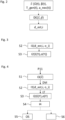
- FIG. 2 shows a flowchart of an exemplary embodiment of the operation of a damage estimator
- Figure 3 shows a flowchart of exemplary embodiment of the method for determining damage-related information of a technical system
- Figure 4 shows a flowchart of an exemplary embodiment of the method for operating a technical system and of the method for constructing a technical system
- Figures 5 to 7 show diagrams useful for understanding the method for determining the damage-related information.
- FIG 1 shows a schematic view of an exemplary embodiment of the technical system 100.
- the technical system is a wind turbine 100 which comprises a tower 20.
- the tower 20 is fixed to the ground by means of a foundation 104.
- a nacelle 106 is rotatably mounted at one end of the tower 20, opposite to the ground.
- the nacelle 106 comprises, for example, a generator which is coupled to a rotor 10 via a gearbox (not shown).
- the rotor 10 comprises three (wind turbine) rotor blades 1, 2, 3, which are arranged on a rotor hub, said rotor hub being connected to a rotor shaft (not shown).
- the rotor 10 is set in rotation by an air flow, for example wind. This rotational movement is transmitted to the generator via the drive train comprising, inter alia, the rotor shaft and the gearbox.
- the generator converts the mechanical energy of the rotor 10 into electrical energy.
- a plc 30 is used for controlling or operating the wind turbine 100.
- a damage estimator DE can be used. The operation of such a damage estimator DE is shown in figure 2 .
- the damage estimator DE receives, as input values s ⁇ , the generator speed Q(t), the generator torque T_gen(t), the pitch angles ⁇ (t) of the rotor blades 1, 2, 3, and the forward-backward bending acceleration a_nec(t) of the nacelle 104. All of these input values s ⁇ can be measured resolved for time t.
- the wind turbine 100 of figure 1 comprises a measurement system 11 with different sensors configured to measure the mentioned input values s ⁇ .
- the damage estimator DE determines, from the input values s ⁇ , the time resolved forward-backward bending moment of the tower 20. From this bending moment, the damage estimator DE performs a static load calculation, e.g. according to IEC 61400-1. As a result, the damage estimator DE delivers estimated damages d_est,i for each time span i.
- the time spans i each have a length, for example, of 10 minutes.
- the damage estimator DE also makes some assumptions about physical parameters, measurement uncertainties and so on.
- the input values are summarized as uncertainty parameters p ⁇ . They may be set as default values in the damage estimator.
- the damage estimator DE can be used with real input values s ⁇ , i.e. values which have been measured at a real wind turbine, but also with simulated input values s ⁇ , i.e. values which have been simulated using a simulation of the wind turbine.
- the damage estimator will provide estimated damages d_est,i. Simulations can also provide the actual damages d_i at the end of each time span i. This can be compared to the estimated damages d_est,i obtained with simulated input values s ⁇ , as will be discussed later.
- first information I1 is provided.
- the first information I1 is representative of the estimated damages d_est,i to a component of the technical system in different time spans i during operation of the technical system.
- the estimated damages d_est,i are determined with the help of a damage estimator DE.
- the first information I1 is, furthermore, representative of the operating points o_i of the technical system 100 during the time spans i.
- second information I2 is determined depending on the first information I1.
- the second information I2 is determined using a stochastic model which treats the accumulated damage Y of the component accumulated over several or all time spans i as a stochastic variable. Thereby, the realization of the estimated damages d_est,i at the end of each time span i and the realization of the operating points o_i during each time span i as extractable from the first information I1 is set as a condition.
- the second information I2 is representative of the expectation value E(Y) of this accumulated damage Y and/or of the uncertainty ⁇ (Y) of this accumulated damage Y.
- the estimated damages d_est,i could, for example, be the estimated damages obtained with the damage estimator DE described in connection with figure 2 .
- the operating points o_i for each time span may be the wind velocities acting on the rotor 10 and averaged over the respective time span i.
- the expectation value E(Y) of the accumulated damage Y and the uncertainty ⁇ (Y) of the accumulated damage Y may be parametrized according to formulas (6) and (8).
- the uncertainty parameters p ⁇ are thereby treated as random variables P ⁇ .
- the full dots represents d_est,i and d_i for an operating point o_i being a wind speed of 10 m/s.
- a straight line with the slope of m(10m/s) is fitted through these points.
- the open dots represent d_est,i and d_i for an operating point being a wind speed of 24 m/s.
- a straight line with the slope of m(24m/s) is fitted through these points.
- a value m(o_i) can be obtained for all operating points o_i. This is illustrated in figure 6 , showing the values m(o_i) for different operating points o_i.
- the simulations reveal that the damage estimator systematically overestimates the damage at low wind speeds (low values of o_i) and systematically underestimates the damage at high wind speeds (high values of o_i).
- the actual damage d_i of the tower 20 of a real wind turbine cannot be determined, which is why the arrow to d_i is crossed out. But, for a real wind turbine, the damage estimator DE can be used.
- An uncertainty which enters into the damage estimator DE in this case is the measurement uncertainty p ⁇ meas . Indeed, the measurements of Q(t), T_gen(t), ⁇ (t) and a_nec(t), underlie a measurement uncertainty p ⁇ meas , which are, for example, instrument errors like offset errors, gain errors, nonlinearity errors and other errors of all the input signals of the damage estimator DE.
- Physical uncertainty comes from the fact that, in the simulation, default values are usually used for physical parameters. In reality, those physical parameters show unknown variations from the default values used in the simulations. Therefore, it again makes sense to use P ⁇ phys instead of p ⁇ phys .
- Model uncertainties have to do with the simulation method.
- the equations used to model the real world are not perfect and numerical errors also occur.
- Model uncertainty is depicted in figure 7 by the arrow on the left-hand side labeled " p ⁇ _mod ". Parametrizing this uncertainty with p ⁇ mod is purely theoretical. This uncertainty is neglected in the presented method.
- the first multiplicative factor can now be determined.
- p q E P q ⁇ ⁇ X q E P q + ⁇ P q o i ⁇ ⁇ X q E P q ⁇ ⁇ P q o i 2 ⁇ P q
- sample means of simulated data points d_i/d_est,i can be used to approximate the expectation value E(D_i/D_est,i).
- simulations with "detuned values" for p ⁇ need to be conducted. 1.
- measurements P11 are taken with the help of the measurement system 11.
- Input values s ⁇ for the damage estimator DE are determined from these measurements P11.
- the third information I3, provided in step S1, is representative of these input values s ⁇ .
- the first information I1 is determined depending on the third information I3 using the damage estimator DE.
- the second information I2 is determined depending on the first information I1. All values which are not accessible when using real data of a real wind turbine, like E ( ⁇ X q ( p q , o i )), m ( o i ) and ⁇ ⁇ X q ⁇ p q
- p q E P q for each operating point o_i can be extracted from the look-up table LT filled with the reference values. In this way, the expectation value E(Y) and the uncertainty ⁇ (Y) can also be determined for the real wind turbine. These values are stored in the second information I2.
- step S4 fourth information I4 is determined depending on the second information I2.
- the fourth information I4 is representative of the remaining lifetime of the wind turbine 100 or the tower 20, respectively.
- an output signal OS is generated depending on the second information I2 or the fourth information I4, respectively.
- the output signal OS is configured to set the operation of the wind turbine 100 and/or to cause scheduling of maintenance of the wind turbine.
- the output signal OS causes a change of operation, like a reduction of the power output and/or a reduction of power extraction.
- the output signal OS may indicate the remaining lifetime to an operator so that he/she can schedule maintenance of the wind turbine.
- step S6 can be executed in which a new wind turbine 100 is constructed or designed, respectively, depending on the second I2 or fourth information I4, respectively.
Landscapes
- Engineering & Computer Science (AREA)
- Mechanical Engineering (AREA)
- Life Sciences & Earth Sciences (AREA)
- Sustainable Development (AREA)
- Sustainable Energy (AREA)
- Chemical & Material Sciences (AREA)
- Combustion & Propulsion (AREA)
- General Engineering & Computer Science (AREA)
- Evolutionary Computation (AREA)
- Theoretical Computer Science (AREA)
- Artificial Intelligence (AREA)
- Management, Administration, Business Operations System, And Electronic Commerce (AREA)
- Testing Of Devices, Machine Parts, Or Other Structures Thereof (AREA)
Abstract
The method for determining damage-related information of a technical system (100) comprises a step of providing first information (11) being representative of estimated damages (d_est,i) to a component (20) of the technical system in different time spans (i) during operation of the technical system, wherein the estimated damages are determined with the help of a damage estimator (DE). The first information is also representative of operating points (o_i) of the technical system during the time spans. The method further comprises a step of determining second information (12) depending on the first information, wherein the second information is determined using a stochastic model which treats the accumulated damage (Y) of the component accumulated over several time spans as a stochastic variable with the realization of the estimated damages at the end of each time span and the realization of the operating points during each time span as a condition. The second information is representative of an expectation value (E(Y)) of this accumulated damage and/or an uncertainty (σ(Y)) of this accumulated damage.
Description
- The present disclosure relates to a method for determining damage-related information of a technical system. Furthermore, the present disclosure relates to a method for operating a technical system and a method for constructing a technical system. Moreover, the present disclosure relates to a computer program, a computer-readable data carrier, a computing device and a technical system.
- The reconstruction of load experienced by the components of a technical system and the prediction of the remaining useful lifetime (RUL) is an important topic for the operation as well as the construction of such a technical system. The reconstruction can be done with different algorithms, including black boxes and white boxes. Typical fields of application concern technical systems with increased safety requirements or complex capital goods, like airplanes, nuclear power plants, production plants, machine tools, wind turbines etc.
- Nowadays damage estimators (also called load estimators) are often used to reconstruct the experienced damage of a component of the technical system. Damage estimators detect mechanical loads as "virtual sensors" without instrumentation efforts and deliver, as an output, the damage equivalent load (DEL) for a certain time span. Advantages of load estimators compared to direct load measurements (e.g. by means of strain gauges) are that no instrumentation expenses are needed, the maintenance costs are significantly lower and data are available during the entire life cycle.
- One object to be achieved is to provide an improved method for determining damage-related information of a technical system, particularly a method with which the accumulated damage to a component of the technical system can be determined more precisely and/or a method with which the uncertainty of the estimated accumulated damage can be reliably determined. Further objects to be achieved are to provide a method for operating a technical system and a method for constructing a technical system by using the information obtained with the method for determining the damage-related information. Other objects to be achieved are to provide a computer program, a computer readable data-carrier, a computing device and a technical system with which these methods can be executed.
- Firstly, the method for determining damage-related information of a technical system is specified.
- According to an embodiment, the method for determining damage-related information of a technical system comprises a step of providing first information being representative of estimated damages to a component of the technical system in different time spans during operation of the technical system, wherein the estimated damages are determined with the help of a damage estimator. The first information is also representative of operating points of the technical system during the time spans. The method further comprises a step of determining second information depending on the first information, wherein the second information is determined using a stochastic model which treats the accumulated damage of the component accumulated over several time spans as a stochastic variable with the realization of the estimated damages at the end of each time span and the realization of the operating points during each time span as a condition. The second information is representative of an expectation value of this accumulated damage and/or an uncertainty of this accumulated damage.
- The present invention is, inter alia, based on the recognition that, depending on the fidelity of the damage estimator, it may under- or overestimate the damage compared to the true damage. For example, a damage estimator for a wind turbine may underestimate the damage at low wind speeds and overestimate the damage at high wind speeds. Besides this, measurement errors of the estimator input signals, for example of the tower top acceleration, may lead to errors in the damage estimated with the damage estimator for a certain time span. For example, for predicting the RUL, the accumulated damage over the whole operation time, i.e. the damages summed up over all time spans, needs to be determined.
- In this invention, the accumulated damage is, instead, treated as a stochastic variable, also called "random variable", aiming to find the long-term expectation value of the damage in order to compensate for systematic estimation errors. It has turned out that with this method a more precise estimation of the accumulated damage and a more precise estimation of the uncertainty of the estimated accumulated damage is achieved. This is not only important for predicting the RUL of a technical system, but also for improving the design/construction phase for a technical system.
- The method specified herein is, in particular, a computer implemented method, i.e. is performed by a computer or a processor.
- Herein, when information is representative of a certain quantity or certain quantities, this means that the quantity or quantities can be extracted from the information directly or the quantity/quantities can at least be derived from the information. In other words, the quantity/quantities is/are stored in the information, or at least data are stored in the information, from which the quantity/quantities can be derived or determined or calculated, respectively. Furthermore, here and in the following, information is, in particular, electronic information, like electronic data.
- Here and in the following, indices "µ" when used outside of formulas may be written as "_µ" for better readability.
- The damage estimator provides, for each time span i, at least one estimated damage, also called "d_est,i". Particularly, d_est,i is the damage of the component at the end of the time span i. Each time span is, for example, between 1 min and 1 h, e.g. 10 min.
- The component of the technical system, for which an estimated damage is provided, may be any technical component of the technical system which experiences fatigue damage during operation. It may be a purely mechanical and/or electronic component of the technical system. In the case of the technical system being a wind turbine, the component may be the tower or a blade or the yaw system or the pitch system etc.
- A basic assumption of the stochastic model is that, for each time span, there is the unknown actual damage of the component. In the stochastic model, this unknown actual damage is modeled as a random variable or a stochastically distributed variable, also called "D_i", respectively. The realization d_i of D_i at the end of time span i cannot be determined. Instead, a probability density function for D_i, also called "pdf(D_i)", may be investigated.
- The estimated damage for the time span i is also assumed to be a random variable, also called "D_est", in the stochastic model. At the end of each time span i, however, the realization d_est,i of D_est,i is observed with the damage estimator. In the stochastic model, the pdf(D_i) can then be refined using the realization d_est,i of D_est,i as stored in the first information as a condition so that the pdf(Di) becomes a conditional probability density function.
- A further parameter which influences the actual damage of the component is the operating point during time span i. The operating points, herein also called "o_i", are, in particular, quantities characterizing the quasi-static state of the technical system during each time span. The operating points are, particularly, selected such that, for a given operating point, the actual damage and the estimated damage of the damage estimator are statistically in a fixed ratio.
- In the case of the technical system being or comprising a wind turbine, the operating points may be the wind speeds averaged for each time span. Alternatively, it could also be the averaged thrust acting on the wind turbine, the controller mode, the operating mode etc.
- The operating point is actually also an unknown, i.e. a random or stochastically distributed variable, also called "O_i". It is, however, assumed that the operating points can be determined with sufficient accuracy and fidelity so that the operating points are not treated as random variables but the realization o_i of O_i as stored in the first information is used as a condition in the model instead.
- Thus, "realization of a certain variable as a condition" herein means that a variable is not treated as a random variable but, instead, a concrete value is used. This concrete value may be determined with the help of measurements or with the help of simulations, for example. Here and in the following, when talking about the estimated damage or the operating point, the concrete values from the first information, i.e. d_est,i and o_i are meant. Otherwise, if the corresponding random variables D_est,i or O_i are meant instead, this will be explicitly mentioned.
- With the realization of the operation points, i.e. the concrete values o_i, and the realization of the estimated damages, i.e. the concrete values d_est,i, as a condition, the accumulated damage is actually a conditional probability density function having a conditional expectation value and a conditional standard deviation. However, for large time spans i, which is herein assumed to be fulfilled, the conditional standard deviation is considered to be negligible because of the law of large numbers. The conditional expectation value y of this conditional probability density function, i.e. of the accumulated damage, is:

- Here, for the ease of notation,


- For example, the uncertainty parameters


- In the stochastic model, the random variable Y of formula (2) may be used as the accumulated damage.
- The second information may be representative of the expectation value of the accumulated damage. Particularly, determining the second information comprises determining the expectation value of the random variable Y of formula (2) by using the stochastic model.
- Additionally or alternatively, the second information is representative of the uncertainty of the accumulated damage. That is, determining the second information may comprise determining this uncertainty by using the stochastic model. In particular, the second information is representative of the uncertainty of the random variable Y of formula (2). The uncertainty may be the standard deviation.
- According to at least one embodiment, the stochastic model approximates the accumulated damage as the sum of the product of three multiplicative factors summed up over the time spans i.
- According to at least one embodiment, the first multiplicative factor, also called "


- According to at least one embodiment, the second multiplicative factor, also called "m(oi )" depends only on the operating point (o_i) of the technical system and represents systematic bias of the damage estimator as a function of the operating point. The second multiplicative factor may be determined with the help of fitting. For example, it is determined using simulations for determining the real damage values (d_i) and the load estimator for determining the estimated damages (d_est,i).
- According to at least one embodiment, the third multiplicative factor is the estimated damage (d_est,i), i.e. as obtained from the damage estimator or from the first information, respectively.
- Formulas (1) and (2) may be written as follows:


- Formula (3) can be approximated as

- The index q stands for the individual uncertainty parameters, called "p_q", of

- According to at least one embodiment, at least one uncertainty parameter, i.e. one or more, affecting the performance of the damage estimator is assumed to be a random uncertainty parameter in the stochastic model. Particularly at least one p_q of


- According to at least one embodiment, the random uncertainty parameter is propagated through the stochastic model, particularly through formula (5) of the stochastic model.
- The propagation of the random input variable through the model may be done using the so-called GUM method. The GUM method is described in International Organization for Standardization. ISO/IEC Guide 98-3:2008: Uncertainty of measurement - Part 3: Guide to the expression of uncertainty in measurement (GUM:1995). 2008, the content of which is hereby incorporated by reference.
- According to at least one embodiment, for determining the expectation value of the accumulated damage and/or the uncertainty of the accumulated damage, the first multiplicative factor is linearized around the expectation value of the at least one random uncertainty parameter. Then, only the expectation value of the at least one random uncertainty parameter and/or the standard deviation of the random uncertainty parameter are propagated through the stochastic model.
- Applying the forward propagation, e.g. using the GUM method to formula (5), and applying the linearization around the expectation value of the at least one random uncertainty parameter, the expectation value of the accumulate damage can be written as

- The uncertainty, herein also called "σ(Y)", of the accumulated damage can then be expressed as


- According to at least one embodiment, the stochastic model treats the uncertainty of the accumulated damage as the square root of a sum. The sum is summed over the random uncertainty parameters. Each summand of the sum is the square of a product of two multiplicative factors, namely a fourth and a fifth multiplicative factor. The fourth multiplicative factor, also called "


- The fifth multiplicative factor, also called "σ(Pq )", represents the standard deviation of the random input variable (P_q).
- According to at least one embodiment, the fourth multiplicative factor depends on the second multiplicative factors and on the third multiplicative factors (see, for example, formula (8)).
- According to at least one embodiment, the first multiplicative factor and the second multiplicative factor are determined depending on the operating points of the first information and with the help of a look-up table having stored therein reference first and second multiplicative factors for different operating points, also called "

- Likewise, the reference factors


- According to at least one embodiment, the method further comprises a step of providing third information which is representative of at least one input value obtained during operation of the technical system. For example, the third information is determined depending on measurements. In the case of the technical system being or comprising a wind turbine, the at least one input value of the third information is, for example, the generator speed and/or the pitch angles and/or the thrust force and/or the nacelle acceleration. These values can indeed be measured during operation of the wind turbine. From these input values the damage estimator calculates, for example, the bending moment acting on the tower and, accordingly, determines the estimated damage of the tower.
- According to at least one embodiment, the first information is determined depending on the third information by using the at least one input value as an input for the damage estimator.
- According to at least one embodiment, the method comprises a step of determining fourth information depending on the second information. The fourth information is representative of the remaining lifetime of the component of the technical system and/or of the uncertainty with which the remaining lifetime is determined. Indeed, with the expectation value of the accumulated damage and/or the uncertainty of the accumulated damage, the remaining lifetime and/or the uncertainty of the determined remaining lifetime of the component can be determined. The uncertainty of the remaining lifetime is, for example, the confidence level of the remaining lifetime. The remaining lifetime may be proportional to y_max - E(Y), wherein Y-max is the maximum allowed damage to the component.
- According to at least one embodiment, the technical system is or comprises a wind turbine. The component for which the damage estimator determines the estimated damage is, for example, the tower.
- According to at least one embodiment, the operating points of the first information are the wind speeds during the different time spans.
- Next, the method for operating a technical system is specified. The method comprises a step in which the method for determining damage-related information of the technical system is executed. In a further step, an output signal is determined and generated depending on the second information, wherein the output signal is configured to set the operation of the technical system and/or to cause a scheduling of maintenance of the technical system.
- The output signal is, particularly, determined for the same technical system for which the method for determining damage-related information is executed.
- For example, if the second information is representative of the expectation value of the accumulated damage to exceed a threshold value, the operation mode of the technical system may be changed or the technical system may turned off. For example, in the case of a wind turbine, the rotational velocity and/or the power output may be reduced. Also the wind sector management may be adapted.
- Additionally or alternatively, the output signal may be configured to cause a scheduling, particularly a rescheduling of maintenance of the technical system. For example, the output signal causes a noticeable warning signal so that an operator schedules maintenance.
- According to at least one embodiment, the third information is determined depending on measurements. The measurements may be taken during operation of the technical system. For example, in case of a wind turbine, the measurement of the power output and/or of the pitch angles and/or of the top tower acceleration may be used for determining the third information.
- Next, the method for constructing a technical system is specified. This method comprises a step of executing the method for determining damage-related information of a technical system as specified herein. In a further step, a technical system is constructed depending on the second information.
- The constructed technical system is, particularly, a different technical system for which the method for determining damage-related information is executed.
- As an example, the method for determining damage-related information may be applied to a real technical system, e.g. a real wind turbine. A new technical system, e.g. a new wind turbine, may then be constructed depending on the second information. For example, the new technical system can be constructed less conservatively based on the second information.
- Next the computer program, the computer-readable data carrier and the computing device are specified.
- The computer program comprises instructions which, when the program is executed by a computer or a computing device, respectively, cause the computer/computing device to carry out any of the methods described herein.
- The computer-readable data carrier has the computer program stored thereon.
- The computing device is configured to perform the methods according to any one of the embodiments described herein. For example, the computing device comprises at least one processor and/or at least one programmable logic controller, plc for short. It may further comprise interfaces for receiving information/signals and/or for the output of information/signals.
- Next, the technical system is specified. The technical system is, in particular, configured to perform any one of the methods described herein. Therefore, all features described for the method are also described for the technical system and vice versa.
- According to an embodiment, the technical system comprises at least one measurement system configured to take measurements with the help of which at least one input value for a damage estimator is determinable during operation of the technical system. Furthermore, the technical system comprises the computing device specified herein. The computing device is signally connected or is signally connectable to the measurement system in order to receive the measurements of the measurement system.
- Hereinafter, the method for determining damage-related information of a technical system, the method for operating a technical system and the method for constructing a technical system as well as the technical system will be explained in more detail with reference to drawings on the basis of exemplary embodiments. The accompanying figures are included to provide further understanding. In the figures, elements of the same structure and/or functionality may be referenced by the same reference signs. It is to be understood that the embodiments shown in the figures are illustrative representations and are not necessarily drawn to scale. In so far as elements or components correspond to one another in terms of their function in different figures, the description thereof is not repeated for each of the following figures. For the sake of clarity, elements might not appear with corresponding reference symbols in all figures.
-
Figure 1 shows an exemplary embodiment of the technical system, -
Figure 2 shows a flowchart of an exemplary embodiment of the operation of a damage estimator, -
Figure 3 shows a flowchart of exemplary embodiment of the method for determining damage-related information of a technical system, -
Figure 4 shows a flowchart of an exemplary embodiment of the method for operating a technical system and of the method for constructing a technical system, -
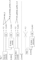
Figures 5 to 7 show diagrams useful for understanding the method for determining the damage-related information. -
Figure 1 shows a schematic view of an exemplary embodiment of thetechnical system 100. Here, the technical system is awind turbine 100 which comprises atower 20. Thetower 20 is fixed to the ground by means of afoundation 104. Anacelle 106 is rotatably mounted at one end of thetower 20, opposite to the ground. Thenacelle 106 comprises, for example, a generator which is coupled to arotor 10 via a gearbox (not shown). Therotor 10 comprises three (wind turbine)rotor blades - During operation, the
rotor 10 is set in rotation by an air flow, for example wind. This rotational movement is transmitted to the generator via the drive train comprising, inter alia, the rotor shaft and the gearbox. The generator converts the mechanical energy of therotor 10 into electrical energy. Aplc 30 is used for controlling or operating thewind turbine 100. - The wind acting on the rotor and the thrust generated by the
rotating rotor blades wind turbine 100. This results in (fatigue) damage of the components. In the following, the load and damage of thetower 20 are studied in greater detail. - Due to the acting forces, the
tower 20 is bent during operation. In order to determine the damage of thetower 20 induced by this bending, a damage estimator DE can be used. The operation of such a damage estimator DE is shown infigure 2 . - For example, the damage estimator DE receives, as input values

rotor blades nacelle 104. All of these input values
wind turbine 100 offigure 1 comprises ameasurement system 11 with different sensors configured to measure the mentioned input values
- The damage estimator DE determines, from the input values

tower 20. From this bending moment, the damage estimator DE performs a static load calculation, e.g. according to IEC 61400-1. As a result, the damage estimator DE delivers estimated damages d_est,i for each time span i. The time spans i each have a length, for example, of 10 minutes. - The damage estimator DE also makes some assumptions about physical parameters, measurement uncertainties and so on. The input values are summarized as uncertainty parameters

- It is important to understand that the damage estimator DE can be used with real input values


- An exemplary embodiment of the method for determining load related information of a technical system is shown in
figure 3 with the help of a flowchart. In a step S2, first information I1 is provided. The first information I1 is representative of the estimated damages d_est,i to a component of the technical system in different time spans i during operation of the technical system. The estimated damages d_est,i are determined with the help of a damage estimator DE. The first information I1 is, furthermore, representative of the operating points o_i of thetechnical system 100 during the time spans i. In a step S3, second information I2 is determined depending on the first information I1. The second information I2 is determined using a stochastic model which treats the accumulated damage Y of the component accumulated over several or all time spans i as a stochastic variable. Thereby, the realization of the estimated damages d_est,i at the end of each time span i and the realization of the operating points o_i during each time span i as extractable from the first information I1 is set as a condition. The second information I2 is representative of the expectation value E(Y) of this accumulated damage Y and/or of the uncertainty σ(Y) of this accumulated damage Y. - The estimated damages d_est,i could, for example, be the estimated damages obtained with the damage estimator DE described in connection with
figure 2 . The operating points o_i for each time span may be the wind velocities acting on therotor 10 and averaged over the respective time span i. - The expectation value E(Y) of the accumulated damage Y and the uncertainty σ(Y) of the accumulated damage Y may be parametrized according to formulas (6) and (8). The uncertainty parameters


- The second multiplicative factor m(oi ) representing the systematic bias of the damage estimator DE is determined with the help of simulations. For example, m(oi ) is calculated with a statistical evaluation such that

- This means that simulations of the
wind turbine 100 are performed so that actual damages d_i for different time spans i are obtained. Simulated input values


figures 5 and 6 . - In
figure 5 , the full dots represents d_est,i and d_i for an operating point o_i being a wind speed of 10 m/s. A straight line with the slope of m(10m/s) is fitted through these points. The open dots represent d_est,i and d_i for an operating point being a wind speed of 24 m/s. Also here a straight line with the slope of m(24m/s) is fitted through these points. In this way, a value m(o_i) can be obtained for all operating points o_i. This is illustrated infigure 6 , showing the values m(o_i) for different operating points o_i. - The simulations reveal that the damage estimator systematically overestimates the damage at low wind speeds (low values of o_i) and systematically underestimates the damage at high wind speeds (high values of o_i).
- The functions ΔX q (Pq, oi ) and
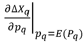


- Measurement uncertainty parameters are listed in

- Physical uncertainty parameters are listed in

- Model uncertainty parameters are listed in

- The sources of these uncertainty parameters can be understood with the help of
figure 7 . Simulations of the wind turbine are illustrated above the dashed line. A real wind turbine is illustrated below the dashed line. - The actual damage d_i of the
tower 20 of a real wind turbine cannot be determined, which is why the arrow to d_i is crossed out. But, for a real wind turbine, the damage estimator DE can be used. An uncertainty which enters into the damage estimator DE in this case is the measurement uncertainty



figure 7 . - Physical uncertainty comes from the fact that, in the simulation, default values are usually used for physical parameters. In reality, those physical parameters show unknown variations from the default values used in the simulations. Therefore, it again makes sense to use


figure 7 . - Model uncertainties have to do with the simulation method. The equations used to model the real world are not perfect and numerical errors also occur. Model uncertainty is depicted in
figure 7 by the arrow on the left-hand side labeled "

- The first multiplicative factor can now be determined. For this purpose, the two functions ΔX q(Pq , oi ) and


- Also here, sample means of simulated data points d_i/d_est,i can be used to approximate the expectation value E(D_i/D_est,i). However, for those data points, simulations with "detuned values" for

1. Measurement uncertainty parameters
- The measurement uncertainty parameters are not an input for the simulation itself but only for the damage estimator DE. Artificial measurement errors are imposed on the input values of the damage estimator so that, for each of the uncertainty values pq = E(Pq ), pq = E(Pq + σ(Pq )) and pq = E(Pq - σ(Pq )), a set of estimated damages d_est,i is obtained. This is again classified for the operating points o_i, as it is done for determining m(o_i). Then, using formulas (10) and (11), values E(ΔXq (Pq, oi )) and

2. Physical uncertainty parameters
- Since the physical uncertainty parameters are an input of the simulations, simulations have to be performed with the physical uncertainty parameters pq = E(Pq ), pq = E(Pq + σ(Pq )) and pq = E(Pq - σ(Pq )) for each index phys, q. Thus, for each index phys,q, values for d_est,i and d_i are obtained and are then classified for the operating points o_i. Then, for each pair (phys,q, o_i), values E(ΔXq (Pq, oi )) and

- The above-described calculations have been performed for a
simulated wind turbine 100 and by studying the damage of thetower 20. From this, the standard approach to estimate the accumulated damage, i.e. adding up all estimated damages, and the approach described herein, i.e. the accumulated damage is treated as a stochastic variable, have been compared by calculating the ratio

- This means that the standard approach overestimates the accumulated damage by about 14.5 %.
- Moreover,


- That means that the uncertainty of the estimation is about 11% of the expectation value.
- The values for E(ΔXq (Pq, oi )), m(oi ) of formula (6) and

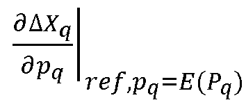
figure 4 . - In
figure 4 , measurements P11 are taken with the help of themeasurement system 11. Input values

- Then, in step S2, the first information I1 is determined depending on the third information I3 using the damage estimator DE. The second information I2 is determined depending on the first information I1. All values which are not accessible when using real data of a real wind turbine, like E(ΔXq (pq, oi )), m(oi ) and

- In step S4, fourth information I4 is determined depending on the second information I2. The fourth information I4 is representative of the remaining lifetime of the
wind turbine 100 or thetower 20, respectively. - In step S5, an output signal OS is generated depending on the second information I2 or the fourth information I4, respectively. The output signal OS is configured to set the operation of the
wind turbine 100 and/or to cause scheduling of maintenance of the wind turbine. For example, the output signal OS causes a change of operation, like a reduction of the power output and/or a reduction of power extraction. The output signal OS may indicate the remaining lifetime to an operator so that he/she can schedule maintenance of the wind turbine. - Additionally or alternatively to step S5, a step S6 can be executed in which a
new wind turbine 100 is constructed or designed, respectively, depending on the second I2 or fourth information I4, respectively. - The invention described herein is not limited by the description in conjunction with the exemplary embodiments. Rather, the invention comprises any new feature as well as any combination of features, particularly including any combination of features in the patent claims, even if said feature or said combination per se is not explicitly stated in the patent claims or exemplary embodiments.
-
- 1
- first rotor blade
- 2
- second rotor blade
- 3
- third rotor blade
- 10
- rotor
- 20
- component/tower
- 11
- measurement system
- 30
- computing device
- 100
- wind turbine
- 104
- foundation
- 106
- nacelle
- I1
- first information
- I2
- second information
- I3
- third information
- I4
- fourth information
- OS
- output signal
- DE
- damage estimator
- d_est,i
- estimated damage
- o_i
- operating point
- i
- time span
- Y
- accumulated damage
- E(Y)
- expectation value of accumulate damage
- σ(Y)
- uncertainty of accumulated damage
- m(oi)
- second multiplicative factor
- LT
- look-up table
- S1 to S5
- method steps

Q(t) generator speed
T_gen(t) generator torque
β (1) pitch angle
a_nec(t forward-backward bending acceleration

E(P_q) expectation value of random uncertainty parameter
Claims (15)
- Method for determining damage-related information of a technical system (100), the method comprising- (S2) providing first information (I1) being representative of- estimated damages (d_est,i) to a component (20) of the technical system (100) in different time spans (i) during operation of the technical system (100), wherein the estimated damages (d_est,i) are determined with the help of a damage estimator (DE), and- operating points (o_i) of the technical system (100) during the time spans (i),- (S3) determining second information (I2) depending on the first information (I1), wherein- the second information (I2) is determined using a stochastic model which treats the accumulated damage (Y) of the component (20) accumulated over several time spans (i) as a stochastic variable with the realization of the estimated damages (d_est,i) at the end of each time span (i) and the realization of the operating points (o_i) during each time span (i) as a condition, and- the second information (I2) is representative of an expectation value (E(Y)) of this accumulated damage (Y) and/or of an uncertainty (σ(Y)) of this accumulated damage (Y).
- Method according to claim 1, wherein- the stochastic model approximates the accumulated damage (Y) as a sum of the product of three multiplicative factors summed up over the time spans (i), wherein- the first multiplicative factor is an uncertainty factor and is dependent on the operating point (o_i) of the technical system (100),- the second multiplicative factor (m(oi )) depends only on the operating point (o_i) of the technical system (100) and represents systematic bias of the damage estimator (DE) as a function of the operating point (o_i),- the third multiplicative factor is the estimated damage (d_est,i).
- Method according to claim 1 or 2, wherein- at least one uncertainty parameter (
 - the random uncertainty parameter is propagated through the stochastic model.
 - Method according to claims 2 and 3, wherein- for determining the expectation value (E(Y)) of the accumulated damage (Y) and/or the uncertainty (σ(Y)) of the accumulated damage (Y), the first multiplicative factor is linearized around the expectation value (E(P_q)) of the at least one random uncertainty parameter (P_q),- the expectation value (E(P_q)) and/or the standard deviation (o(P_q)) of the at least one random uncertainty parameter (P_q) are propagated through the stochastic model.
- Method according to claim 2, wherein- the first multiplicative factor and the second multiplicative factor (m(oi )) are determined depending on the operating points (o_i) and with the help of a look-up table (LT) having stored therein reference first and second (mref (oi )) multiplicative factors for different operating points (o_i).
- Method according to any one of the preceding claims, further comprising- providing third information (I3) which is representative of at least one input value (
 - the first information (I1) is determined depending on the third information (I3) by using the at least one input value (
- Method according to any one of the preceding claims, further comprising- determining fourth information (I4) depending on the second information (I2), wherein- the fourth information (I4) is representative of the remaining lifetime of the component (20) of the technical system (100) and/or of the uncertainty with which the remaining lifetime is determined.
- Method according to any one of the preceding claims, wherein- the technical system (100) is or comprises a wind turbine, and/or- the operating points (o_i) are the wind speeds during the different time spans (i).
- Method for operating a technical system (100) comprising- executing the method for determining damage-related information of the technical system (100) according to any one of claims 1 to 8,- (S5) determining and generating an output signal (OS) depending on the second information (I2), wherein the output signal (OS) is configured to set the operation of the technical system (100) and/or to cause a scheduling of maintenance of the technical system (100).
- Method for operating a technical system (100) according to claim 9, wherein- the method for determining damage-related information is the method according to claim 6 or any one of claims 6 to 8 in their dependency on claim 6,- the third information (I3) is determined depending on measurements (P11) taken during operation of the technical system (100).
- Method for constructing a technical system (100) comprising,- executing the method for determining damage-related information of a technical system (100) according to any one of claims 1 to 8,- (S6) constructing a technical system (100) depending on the second information (I2).
- Computer program comprising instructions which, when the program is executed by a computer, cause the computer to carry out the methods of any one of claims 1 to 11.
- Computer-readable data carrier having the computer program of claim 12 stored thereon.
- Computing device (30) configured to perform the methods of any one of claims 1 to 11.
- Technical system (100) comprising- at least one measurement system (11) configured to take measurements with the help of which at least one input value (
 - at least one computing device (30) according to claim 14, wherein- the computing device (30) is signally connected or signally connectable to the measurement system (11) in order to receive the measurements (P11) of the measurement system (11) .
Priority Applications (3)
| Application Number | Priority Date | Filing Date | Title |
|---|---|---|---|
| EP23218021.6A EP4575222A1 (en) | 2023-12-19 | 2023-12-19 | Method for determining damage-related information of a technical system, method for operating a technical system and method for constructing a technical system |
| PCT/EP2024/086671 WO2025132272A1 (en) | 2023-12-19 | 2024-12-16 | Method for determining damage-related information of a technical system, method for operating a technical system and method for constructing a technical system |
| AU2024407237A AU2024407237A1 (en) | 2023-12-19 | 2024-12-16 | Method for determining damage-related information of a technical system, method for operating a technical system and method for constructing a technical system |
Applications Claiming Priority (1)
| Application Number | Priority Date | Filing Date | Title |
|---|---|---|---|
| EP23218021.6A EP4575222A1 (en) | 2023-12-19 | 2023-12-19 | Method for determining damage-related information of a technical system, method for operating a technical system and method for constructing a technical system |
Publications (1)
| Publication Number | Publication Date |
|---|---|
| EP4575222A1 true EP4575222A1 (en) | 2025-06-25 |
Family
ID=89224316
Family Applications (1)
| Application Number | Title | Priority Date | Filing Date |
|---|---|---|---|
| EP23218021.6A Withdrawn EP4575222A1 (en) | 2023-12-19 | 2023-12-19 | Method for determining damage-related information of a technical system, method for operating a technical system and method for constructing a technical system |
Country Status (3)
| Country | Link |
|---|---|
| EP (1) | EP4575222A1 (en) |
| AU (1) | AU2024407237A1 (en) |
| WO (1) | WO2025132272A1 (en) |
Citations (2)
| Publication number | Priority date | Publication date | Assignee | Title |
|---|---|---|---|---|
| US20190178231A1 (en) * | 2017-12-12 | 2019-06-13 | General Electric Company | Methods of operating a wind turbine |
| US20210123416A1 (en) * | 2018-05-04 | 2021-04-29 | Vestas Wind Systems A/S | Wind turbine control method |
-
2023
- 2023-12-19 EP EP23218021.6A patent/EP4575222A1/en not_active Withdrawn
-
2024
- 2024-12-16 WO PCT/EP2024/086671 patent/WO2025132272A1/en active Pending
- 2024-12-16 AU AU2024407237A patent/AU2024407237A1/en active Pending
Patent Citations (2)
| Publication number | Priority date | Publication date | Assignee | Title |
|---|---|---|---|---|
| US20190178231A1 (en) * | 2017-12-12 | 2019-06-13 | General Electric Company | Methods of operating a wind turbine |
| US20210123416A1 (en) * | 2018-05-04 | 2021-04-29 | Vestas Wind Systems A/S | Wind turbine control method |
Also Published As
| Publication number | Publication date |
|---|---|
| WO2025132272A1 (en) | 2025-06-26 |
| AU2024407237A1 (en) | 2026-05-14 |
Similar Documents
| Publication | Publication Date | Title |
|---|---|---|
| Saint-Drenan et al. | A parametric model for wind turbine power curves incorporating environmental conditions | |
| EP2053241A1 (en) | Method for determining fatigue damage in a power train of a wind turbine | |
| US7684936B2 (en) | Method, apparatus and computer program product for determining a future time of a component | |
| Ronold et al. | Reliability-based fatigue design of wind-turbine rotor blades | |
| Branlard et al. | A digital twin based on OpenFAST linearizations for real-time load and fatigue estimation of land-based turbines | |
| US20200309099A1 (en) | Method and device for predicting wind turbine fault | |
| Henriksen et al. | A simplified dynamic inflow model and its effect on the performance of free mean wind speed estimation | |
| Pimenta et al. | Predictive model for fatigue evaluation of floating wind turbines validated with experimental data | |
| Avendaño-Valencia et al. | Sensitivity driven robust vibration-based damage diagnosis under uncertainty through hierarchical Bayes time-series representations | |
| Epaarachchi et al. | The development of a fatigue loading spectrum for small wind turbine blades | |
| Smolka et al. | On the design of measurement campaigns for fatigue life monitoring of offshore wind turbines | |
| Mouzakis et al. | Fatigue loading parameter identification of a wind turbine operating in complex terrain | |
| WO2018073688A1 (en) | Determining loads on a wind turbine | |
| Valeti et al. | Remaining useful life estimation of wind turbine blades under variable wind speed conditions using particle filters | |
| JP2020180563A (en) | Maintenance method for wind power generation system and wind power generation equipment | |
| Gebel et al. | System identification of offshore wind turbines for model updating and validation using field measurements | |
| Zhang et al. | An effective method of determining the drive-train effciency of wind turbines with high accuracy | |
| WO2025132272A1 (en) | Method for determining damage-related information of a technical system, method for operating a technical system and method for constructing a technical system | |
| Bechhoefer | A method for generalized prognostics of a component using Paris law | |
| Bechhoefer et al. | A state-space model for vibration based prognostics | |
| Klinkov et al. | Wind load observer for a 5MW wind energy plant | |
| Bosmans et al. | Development and embedded deployment of a virtual load sensor for wind turbine gearboxes | |
| Häckell | A holistic evaluation concept for long-term structural health monitoring | |
| Pimenta et al. | New methodology to estimate fatigue from acceleration time series experimentally validated in an onshore and floating offshore wind turbine | |
| da Rosa et al. | Wind turbine blade mass imbalance detection using artificial intelligence |
Legal Events
| Date | Code | Title | Description |
|---|---|---|---|
| PUAI | Public reference made under article 153(3) epc to a published international application that has entered the european phase |
Free format text: ORIGINAL CODE: 0009012 |
|
| STAA | Information on the status of an ep patent application or granted ep patent |
Free format text: STATUS: THE APPLICATION HAS BEEN PUBLISHED |
|
| AK | Designated contracting states |
Kind code of ref document: A1 Designated state(s): AL AT BE BG CH CY CZ DE DK EE ES FI FR GB GR HR HU IE IS IT LI LT LU LV MC ME MK MT NL NO PL PT RO RS SE SI SK SM TR |
|
| STAA | Information on the status of an ep patent application or granted ep patent |
Free format text: STATUS: THE APPLICATION IS DEEMED TO BE WITHDRAWN |
|
| 18D | Application deemed to be withdrawn |
Effective date: 20260103 |