EP4575219A1 - Delivery pipe for engine - Google Patents
Delivery pipe for engine Download PDFInfo
- Publication number
- EP4575219A1 EP4575219A1 EP24218237.6A EP24218237A EP4575219A1 EP 4575219 A1 EP4575219 A1 EP 4575219A1 EP 24218237 A EP24218237 A EP 24218237A EP 4575219 A1 EP4575219 A1 EP 4575219A1
- Authority
- EP
- European Patent Office
- Prior art keywords
- support surface
- outer periphery
- delivery pipe
- main body
- end side
- Prior art date
- Legal status (The legal status is an assumption and is not a legal conclusion. Google has not performed a legal analysis and makes no representation as to the accuracy of the status listed.)
- Pending
Links
Images






Classifications
-
- F—MECHANICAL ENGINEERING; LIGHTING; HEATING; WEAPONS; BLASTING
- F02—COMBUSTION ENGINES; HOT-GAS OR COMBUSTION-PRODUCT ENGINE PLANTS
- F02M—SUPPLYING COMBUSTION ENGINES IN GENERAL WITH COMBUSTIBLE MIXTURES OR CONSTITUENTS THEREOF
- F02M55/00—Fuel-injection apparatus characterised by their fuel conduits or their venting means; Arrangements of conduits between fuel tank and pump F02M37/00
- F02M55/02—Conduits between injection pumps and injectors, e.g. conduits between pump and common-rail or conduits between common-rail and injectors
- F02M55/025—Common rails
-
- F—MECHANICAL ENGINEERING; LIGHTING; HEATING; WEAPONS; BLASTING
- F02—COMBUSTION ENGINES; HOT-GAS OR COMBUSTION-PRODUCT ENGINE PLANTS
- F02M—SUPPLYING COMBUSTION ENGINES IN GENERAL WITH COMBUSTIBLE MIXTURES OR CONSTITUENTS THEREOF
- F02M55/00—Fuel-injection apparatus characterised by their fuel conduits or their venting means; Arrangements of conduits between fuel tank and pump F02M37/00
- F02M55/004—Joints; Sealings
-
- F—MECHANICAL ENGINEERING; LIGHTING; HEATING; WEAPONS; BLASTING
- F02—COMBUSTION ENGINES; HOT-GAS OR COMBUSTION-PRODUCT ENGINE PLANTS
- F02M—SUPPLYING COMBUSTION ENGINES IN GENERAL WITH COMBUSTIBLE MIXTURES OR CONSTITUENTS THEREOF
- F02M55/00—Fuel-injection apparatus characterised by their fuel conduits or their venting means; Arrangements of conduits between fuel tank and pump F02M37/00
- F02M55/004—Joints; Sealings
- F02M55/005—Joints; Sealings for high pressure conduits, e.g. connected to pump outlet or to injector inlet
-
- F—MECHANICAL ENGINEERING; LIGHTING; HEATING; WEAPONS; BLASTING
- F02—COMBUSTION ENGINES; HOT-GAS OR COMBUSTION-PRODUCT ENGINE PLANTS
- F02M—SUPPLYING COMBUSTION ENGINES IN GENERAL WITH COMBUSTIBLE MIXTURES OR CONSTITUENTS THEREOF
- F02M61/00—Fuel-injectors not provided for in groups F02M39/00 - F02M57/00 or F02M67/00
- F02M61/14—Arrangements of injectors with respect to engines; Mounting of injectors
-
- F—MECHANICAL ENGINEERING; LIGHTING; HEATING; WEAPONS; BLASTING
- F02—COMBUSTION ENGINES; HOT-GAS OR COMBUSTION-PRODUCT ENGINE PLANTS
- F02M—SUPPLYING COMBUSTION ENGINES IN GENERAL WITH COMBUSTIBLE MIXTURES OR CONSTITUENTS THEREOF
- F02M69/00—Low-pressure fuel-injection apparatus ; Apparatus with both continuous and intermittent injection; Apparatus injecting different types of fuel
- F02M69/46—Details, component parts or accessories not provided for in, or of interest apart from, the apparatus covered by groups F02M69/02 - F02M69/44
- F02M69/462—Arrangement of fuel conduits, e.g. with valves for maintaining pressure in the pipes after the engine being shut-down
- F02M69/465—Arrangement of fuel conduits, e.g. with valves for maintaining pressure in the pipes after the engine being shut-down of fuel rails
-
- F—MECHANICAL ENGINEERING; LIGHTING; HEATING; WEAPONS; BLASTING
- F16—ENGINEERING ELEMENTS AND UNITS; GENERAL MEASURES FOR PRODUCING AND MAINTAINING EFFECTIVE FUNCTIONING OF MACHINES OR INSTALLATIONS; THERMAL INSULATION IN GENERAL
- F16L—PIPES; JOINTS OR FITTINGS FOR PIPES; SUPPORTS FOR PIPES, CABLES OR PROTECTIVE TUBING; MEANS FOR THERMAL INSULATION IN GENERAL
- F16L55/00—Devices or appurtenances for use in, or in connection with, pipes or pipe systems
- F16L55/10—Means for stopping flow in pipes or hoses
- F16L55/115—Caps
-
- F—MECHANICAL ENGINEERING; LIGHTING; HEATING; WEAPONS; BLASTING
- F02—COMBUSTION ENGINES; HOT-GAS OR COMBUSTION-PRODUCT ENGINE PLANTS
- F02M—SUPPLYING COMBUSTION ENGINES IN GENERAL WITH COMBUSTIBLE MIXTURES OR CONSTITUENTS THEREOF
- F02M2200/00—Details of fuel-injection apparatus, not otherwise provided for
- F02M2200/80—Fuel injection apparatus manufacture, repair or assembly
-
- F—MECHANICAL ENGINEERING; LIGHTING; HEATING; WEAPONS; BLASTING
- F02—COMBUSTION ENGINES; HOT-GAS OR COMBUSTION-PRODUCT ENGINE PLANTS
- F02M—SUPPLYING COMBUSTION ENGINES IN GENERAL WITH COMBUSTIBLE MIXTURES OR CONSTITUENTS THEREOF
- F02M2200/00—Details of fuel-injection apparatus, not otherwise provided for
- F02M2200/80—Fuel injection apparatus manufacture, repair or assembly
- F02M2200/8084—Fuel injection apparatus manufacture, repair or assembly involving welding or soldering
-
- F—MECHANICAL ENGINEERING; LIGHTING; HEATING; WEAPONS; BLASTING
- F02—COMBUSTION ENGINES; HOT-GAS OR COMBUSTION-PRODUCT ENGINE PLANTS
- F02M—SUPPLYING COMBUSTION ENGINES IN GENERAL WITH COMBUSTIBLE MIXTURES OR CONSTITUENTS THEREOF
- F02M2200/00—Details of fuel-injection apparatus, not otherwise provided for
- F02M2200/90—Selection of particular materials
- F02M2200/9015—Elastomeric or plastic materials
Definitions
- Patent Document 1 discloses a delivery pipe in which a main body portion having a tubular shape whose one end is open and a plug are each fabricated with a synthetic resin material and the plug is liquid-tightly welded to an opening end portion of the main body portion.
- a delivery passage for supplying fuel is formed along an axis line in the main body portion, a large-diameter portion having a collar shape is formed in one end portion of the main body portion, and the delivery passage is open to an outside via the opening end portion formed in the large-diameter portion.
- the opening end portion is formed for demolding in injection molding of the main body portion, but because the opening end portion has to be blocked for providing a function of distributing fuel, the plug is welded to the large-diameter portion as described above.
- the main body portion When the plug is welded, the main body portion is set to a posture in which the opening end portion is open upward, fixing jigs of an ultrasonic welding device are disposed on a lower surface of the large-diameter portion from its left and right, and the large-diameter portion is supported from a lower area by those fixing jigs.
- the plug is disposed on the large-diameter portion and welded thereto by applying ultrasonic vibrations to the plug while the plug is pressurized from an upper area by a horn of the ultrasonic welding device.
- an injector connection portion to be coupled with an injector On a main body portion of a delivery pipe, for example, an injector connection portion to be coupled with an injector, a bracket portion for attaching the delivery pipe to an engine, and so forth are integrally formed.
- a fixing jig which supports the large-diameter portion from a lower area cannot be disposed in welding work.
- the large-diameter portion is spaced apart upward from the injector connection portion and the bracket portion, and a space in which the fixing jig can be disposed has to be secured.
- the present invention has been made for solving such problems, and an object thereof is to provide a delivery pipe for an engine that can support a pipe main body in a welding posture, in which an opening portion is directed upward, in welding work for a plug and can improve mountability on an engine by previously preventing unnecessary extension of an entire length.
- a delivery pipe for an engine is a delivery pipe for an engine, the delivery pipe including: a pipe main body being formed of a synthetic resin, in which a large-diameter portion having a collar shape is formed on one end side, one end of a fuel passage formed in an internal portion along an axis line has an opening portion formed in the large-diameter portion, and as outer periphery protrusion portions, a bracket portion for attachment to an engine and a plurality of injector connection portions, which are juxtaposed in an axis line direction and to which injectors are respectively connected, are integrally formed with an outer periphery surface; and a plug being joined to the large-diameter portion of the pipe main body and blocking the opening portion, in which a first support surface to be supported by a first fixing jig is formed on the outer periphery protrusion portion positioned closest to one end side, a second support surface to be supported by a second fixing jig is
- first support surface and the second support surface may be formed on opposite sides at 180° around the axis line of the pipe main body as the center.
- the outer periphery protrusion portion positioned closest to one end side may be the injector connection portion
- the first support surface and the second support surface may be surfaces vertical to the axis line
- the first support surface may be formed on an outer periphery surface, which has a cylindrical shape, of the injector connection portion.
- the outer periphery protrusion portion positioned closest to one end side may be the bracket portion, the first support surface and the second support surface may be surfaces vertical to the axis line, and the first support surface may be formed on the bracket portion.
- a reinforcement rib to which the plurality of injector connection portions are coupled may be integrally formed with the outer periphery surface of the pipe main body, and the first support surface may have a region being notched to correspond to the reinforcement rib.
- an engagement portion may be formed in the injector connection portion, the engagement portion maintaining a coupler to be connected to a connector of the injector in a posture directed in an oblique direction to a side of the pipe main body and one end side.
- the second support surface may be formed with a step between the outer periphery surface of the pipe main body and the outer periphery surface of the large-diameter portion, have a surface facing the other end side and being vertical to the axis line, and have a circular-arc-shaped region surrounding the outer periphery surface of the pipe main body.
- the outer periphery protrusion portion positioned closest to one end side may integrally be formed with the large-diameter portion.
- a delivery pipe for an engine can support a pipe main body in a welding posture, in which an opening portion is directed upward, in welding work for a plug and can improve mountability on an engine by previously preventing unnecessary extension of an entire length.
- FIG. 1 is a perspective view illustrating the delivery pipe of the present embodiment
- FIG. 2 is an exploded perspective view thereof
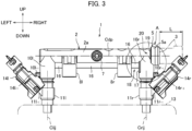
- FIG. 3 is a front view thereof
- FIG. 4 is a right side view thereof.
- a delivery pipe 1 of the present embodiment is applied to a two-cylinder engine which is mounted on a four-wheeled buggy as one kind of a so-called all terrain vehicle (ATV).
- ATV all terrain vehicle
- the engine is positioned below the delivery pipe 1.
- an up-down direction in FIG. 3 will be referred to as up and down
- a left-right direction in FIG. 3 will be referred to as left and right
- directions orthogonal to the page of FIG. 3 will be referred to as front and rear, and each of the directions will thereby be expressed.
- a right side in the present embodiment corresponds to one end side of the present invention
- a left side corresponds to the other end side of the present invention.
- the delivery pipe 1 is formed with a pipe main body 2 and a plug 3 which are formed of a synthetic resin, and those members 2 and 3 are fabricated by injection molding using a synthetic resin material, for example.
- the pipe main body 2 has a tubular shape extending in the left-right direction along an axis line Cdp, and its internal portion serves as a fuel passage 4. A left end of the fuel passage 4 is blocked, a large-diameter portion 5 having a circular collar shape is integrally formed at a right end of the fuel passage 4, and the right end of the fuel passage 4 is open to an outside via an opening portion 6 formed in a right end surface of the large-diameter portion 5.
- a nipple portion 7 is provided to protrude rearward at a left-right center of the pipe main body 2, and in an assembled state where the delivery pipe 1 is assembled to the engine, a fuel hose provided to extend from a vehicle body side is connected to the nipple portion 7.
- Bracket portions 8l and 8r for attachment to the engine are integrally formed respectively on both of left and right sides of the nipple portion 7 on the pipe main body 2.
- Each of the bracket portions 8l and 8r is provided to protrude downward and rearward from an outer periphery surface 2a of the pipe main body 2, and a bush 9 is fitted in each of the bracket portions 8l and 8r by insert molding.
- each of the bracket portions 8l and 8r is fastened to the engine by a bolt from an upper area via the bush 9, and the delivery pipe 1 is thereby fixed to a desired position.
- Each of the injector connection portions 10l and 10r protrudes downward, its outer periphery surface has a cylindrical shape, and at its lower end, a fitting hole is formed (only the fitting hole 10r-2 on the right side is illustrated in FIG. 5 ).
- upper end portions of injectors 111 and 11r are fitted in the fitting hole of the injector connecting portion 10l and the fitting hole 10r-2 of the injector connection portion 10r respectively in a state where the upper end portions are liquid-tightly retained by O-rings 12.
- a lower end portion of each of the injectors 111 and 11r is fitted in a fitting hole of an intake manifold 13 of the engine, which is indicated by a dash-dot-dot line in FIG. 3 , in a liquid-tightly retained state.
- connectors 111-1 and 11r-1 are respectively provided on side surfaces of the injectors 111 and 11r, the connector 111-1 on the left side is directed in an oblique upward-leftward direction, and the connector 11r-1 on the right side is directed in an oblique upward-rightward direction.
- couplers 141 and 14r of harnesses provided to extend from the vehicle body side are respectively connected to those connectors 111-1 and 11r-1, and the injectors 111 and 11r are driven in accordance with driving signals supplied from a controller for engine control.
- an engagement projection portion 10r-1 is provided to protrude rightward on the outer periphery surface of the injector connection portion 10r on the right side, the engagement projection portion 10r-1 is fitted in an engagement recess portion 14r-1 provided to protrude in the coupler 14r on the right side, and rotation of the injector 11r on the right side around an axis line Crij as a center is thereby restrained.
- the engagement projection portion 10r-1 of the injector connection portion 10r on the right side corresponds to "an engagement portion" of the present invention.
- FIG. 5 is an enlarged cross-sectional view corresponding to a section A in FIG. 3
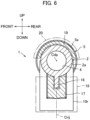
- FIG. 6 is a cross-sectional view taken along line VI-VI in FIG. 5 .
- a reinforcement rib 16 to which the injector connection portions 10l and 10r and the bracket portions 8l and 8r are each coupled, is integrally formed with a lower side of the outer periphery surface 2a of the pipe main body 2, and rigidity of the delivery pipe 1 is thereby enhanced.
- a first support surface 17 having a flat surface shape facing left is formed in the outer periphery surface of the injector connection portion 10r on the right side. In other words, the first support surface 17 has a surface vertical to an axis line Cdp of the pipe main body 2. As hatched in FIG.
- the first support surface 17 has a quadrangular region, which is notched to correspond to the reinforcement rib 16, and reaches the outer periphery surface 2a of the pipe main body 2. Because the injector connection portion 10r on the right side and the bracket portion 8r on the right side are arranged apart in the left-right direction, on the left side of the first support surface 17, a first space 18 is necessarily formed in which fixing jigs 211 and 21r of an infrared welding device described later are capable of being disposed and which is indicated by dash-dot-dot lines. In other words, in the delivery pipe of the present embodiment, the first space 18 is formed between the injector connection portion 10r and the bracket portion 8r.
- the above-described large-diameter portion 5 is integrally formed with a part on the right side of the injector connection portion 10r on the right side. Specifically, as illustrated in FIG. 3 , the large-diameter portion 5 is positioned on a right end side of the injector connection portion 10r on the right side, and a left lower portion of the large-diameter portion 5 is integrally formed with a right upper portion of the injector connection portion 10r.
- a step is formed between an outer periphery surface 5a of the large-diameter portion 5 and the outer periphery surface 2a of the pipe main body 2 having a smaller diameter, and a second support surface 19 is formed with this step. As hatched in FIG.
- the second support surface 19 has a region, which has a circular arc shape of 180° around the axis line Cdp as a center and surrounds the outer periphery surface 2a of the pipe main body 2, and has a flat surface shape facing left as illustrated in FIG. 5 .
- the second support surface 19 has a surface vertical to the axis line Cdp of the pipe main body 2.
- a second space 20 is necessarily formed in which the fixing jigs 211 and 21r are capable of being disposed and which is indicated by dash-dot-dot lines.
- the large-diameter portion 5 is positioned on the right side relative to the injector connection portion 10r.
- the second support surface 19 is positioned on the right side relative to the first support surface 17.
- the opening portion 6 is formed in a right side surface of the large-diameter portion 5, the plug 3 is joined to the large-diameter portion 5 by infrared welding, and the opening portion 6 is thereby blocked.
- grooves 5b and 5c as two (inner and outer) layers are formed in the right side surface of the large-diameter portion 5 to envelop the opening portion 6, and a welding region 5d having a ring shape is formed between the grooves 5b and 5c.
- grooves 3a and 3b as two (inner and outer) layers are formed in a left side surface of the plug 3, and a welding region 3c having a ring shape is formed between the grooves 3a and 3b.
- Those welding regions 5d and 3c are brought into contact and are joined to each other by infrared welding, and the opening portion 6 is blocked by the plug 3.
- the welding regions 5d and 3c of the large-diameter portion 5 and the plug 3 which are not yet welded, slightly protrude in directions to approach each other compared to their inner and outer peripheries, and in the welding work, those protruding portions melt, as welding margins, into each other and are welded to each other.
- cross-sectional shapes of the welding regions 5d and 3c are not limited to the above and can arbitrarily be changed.
- the delivery pipe 1 configured in such a manner is assembled to the engine, and during an operation of the engine, fuel is supplied from the fuel hose, via the nipple portion 7, and to the delivery pipe 1. Fuel is distributed to the injector connection portions 10l and 10r via the fuel passage 4, injected into the intake manifold 13 in accordance with opening and closing of the injectors 111 and 11r, mixed with intake air, supplied as air-fuel mixture to interiors of the cylinders of the engine, and used for combustion.
- FIG. 7 is a front view illustrating the pipe main body 2 which is supported by the fixing jigs in the welding work for the plug 3
- FIG. 8 is a front view illustrating the pipe main body 2 in a case where the plug 3 is pressurized by a movable jig
- FIG. 9 is a plan view illustrating the pipe main body 2 which is supported by the fixing jigs.
- the welding work for the plug 3 is carried out while the pipe main body 2 is retained in a welding posture in which the opening portion 6 is directed upward and the fixing jigs 211 and 21r are disposed from left and right. Accordingly, in the following description, an up-down direction along the axis line of the pipe main body 2 in the welding posture in FIG. 7 will be referred to as up and down, and a left-right direction in which the jigs are arranged will be referred to as left and right.
- the fixing jig 21r on the right side in the present embodiment corresponds to "a first fixing jig" of the present invention
- the fixing jig 211 on the left side in the present embodiment corresponds to "a second fixing jig” of the present invention.
- the pipe main body 2 is set to the welding posture, and the fixing jigs 211 and 21r of the infrared welding device are disposed from left and right. Because the first space 18 is formed on a lower side of the first support surface 17, the fixing jig 21r on the right side is disposed in the first space 18 without any problem and supports the first support surface 17 of the injector connection portion 10r from a lower area. In a planar view in FIG. 9 , because the first support surface 17 is notched to correspond to the reinforcement rib 16, the fixing jig 21r also has a shape which is notched to correspond to the reinforcement rib 16.
- the fixing jig 211 on the left side is disposed in the second space 20 without any problem and supports the second support surface 19 of the large-diameter portion 5 from a lower area.
- the fixing jig 211 also has a shape which is hollowed out into a circular arc corresponding to the outer periphery surface 2a of the pipe main body 2.
- the first and second support surfaces 17 and 19 are supported from the lower areas by the fixing jigs 211 and 21r in such a manner, and the pipe main body 2 is thereby maintained in a desired welding posture in which the opening portion 6 is directed upward.
- a movable jig 22 to be moved up and down by a servo cylinder which is not illustrated, is positioned above the large-diameter portion 5, and the plug 3 is fixed to the movable jig 22.
- the large-diameter portion 5 and the plug 3 are spaced apart in the up-down direction, an infrared lamp 23 is inserted between those as indicated by dash-dot-dot lines, and the welding regions 5d and 3c are irradiated with infrared rays and are melted.
- the infrared lamp 23 is retracted to a position indicated by solid lines, and the plug 3 is lowered together with the movable jig 22 by the servo cylinder as illustrated in FIG. 8 and is pressurized and press-bonded onto the large-diameter portion 5.
- the welding regions 5d and 3c are welded together, the plug 3 is joined to the large-diameter portion 5, and the opening portion 6 is thereby blocked.
- a major characteristic of the delivery pipe 1 of the present embodiment is that instead of the large-diameter portion 5, the existing injector connection portion 10r formed on the pipe main body 2 is supported from the lower area by the fixing jig 21r on the right side.
- the fixing jig 21r on the right side similarly to supporting the first support surface 17 of the large-diameter portion 5 by the fixing jig 211 on the left side, a space for disposing the fixing jig 21r on a lower side of the large-diameter portion 5 has to be secured.
- the large-diameter portion 5 is arranged apart upward from the injector connection portion 10r on the right side, and as indicated by dash-dot-dot lines in FIG. 3 , an entire length of the delivery pipe 1 is unnecessarily extended by a dimension L.
- the existing injector connection portion 10r is used for support by the fixing jig 21r on the right side, and the large-diameter portion 5 thereby does not have to be arranged apart from the injector connection portion 10r. Consequently, as indicated by solid lines in FIG. 3 , the large-diameter portion 5 can integrally be formed with the part on the right side of the injector connection portion 10r, and the entire length of the delivery pipe 1 can thereby be shortened by the dimension L compared to a delivery pipe of Patent Document 1. Shortening of the entire length of the delivery pipe 1 leads to an improvement in mountability of the delivery pipe 1 in a limited engine room of a four-wheeled buggy, such as expansion of flexibility of arrangement of the delivery pipe 1 in the engine room.
- the engagement projection portion 10r-1 is provided to protrude rightward on the outer periphery surface of the injector connection portion 10r on the right side, and the engagement projection portion 10r-1 makes it possible to maintain the connector 11r-1 and the coupler 14r in postures directed upward and rightward as illustrated in FIGs. 3 and 4 , in other words, postures directed to the pipe main body 2 side and the right side.
- protrusion of the coupler 14r in a front-rear direction can be prevented.
- a shape of a whole unit of the delivery pipe 1 which includes the injectors 111 and 11r, the connectors 111-1 and 11r-1, and the coupler 141 and 14r needs an occupied space in the left-right direction and the up-down direction to some extent but hardly needs an occupied space in the front-rear direction because no protruding portion is present.
- mountability of the delivery pipe 1 in the engine room can further be improved.
- the second support surface 19 of the large-diameter portion 5 has the flat surface shape, and the first support surface 17 is intentionally formed to have the flat surface shape on the outer periphery surface, which has the cylindrical shape, of the injector connection portion 10r.
- the first support surface 17 and the second support surface 19 are formed on opposite sides at 180° around the axis line Cdp of the pipe main body 2 as the center. Because of the combination of those factors, the fixing jigs 211 and 21r can uniformly receive pressurization force from the movable jig 22 and can thereby stably support the pipe main body 2, and this contributes to proper welding of the plug 3 and further to a quality improvement.
- the first support surface 17 is notched to correspond to the reinforcement rib 16, and the fixing jig 21r also has the shape which is notched to correspond to the reinforcement rib 16.
- the first support surface 17 and the fixing jig 21r abut each other in a large area in a planar view and abut to a region close to the axis line Cdp of the pipe main body 2 in the left-right direction, in other words, to a region close to the pressurization force received from the movable jig 22, and because of the combination of those circumstances, the first support surface 17 can further stably be supported.
- the second support surface 19 has the circular arc shape surrounding the outer periphery surface 2a of the pipe main body 2, and the fixing jig 211 also has the shape which is hollowed out into the circular arc corresponding to the outer periphery surface 2a of the pipe main body 2.
- the second support surface 19 and the fixing jig 211 abut each other in a large area in a planar view and abut to a region close to the axis line Cdp of the pipe main body 2 in the left-right direction, in other words, to a region close to the pressurization force received from the movable jig 22, and because of the combination of those circumstances, the second support surface 19 can further stably be supported.
- the above point contributes to proper welding of the plug 3 and further to a quality improvement.
- aspects of the present invention are not limited to this embodiment.
- the above embodiment is embodied as the delivery pipe 1 to be applied to the two-cylinder engine mounted on the four-wheeled buggy, but this is not restrictive.
- aspects of the present invention may be applied to a passenger vehicle, a motorcycle, a bicycle with an electric motor, or the like as a vehicle on which an engine is mounted, and a type of an engine can arbitrarily be changed.
- the first support surface 17 is formed on the injector connection portion 10r on the right side as the outer periphery protrusion portion, but this is not restrictive. Arrangement of the injector connection portions 10l and 10r and the bracket portions 81 and 8r on the pipe main body 2 is changed in accordance with various conditions such as requests from the engine side or spaces in the engine room, for example. Thus, in FIG. 3 , it is possible that positions of the injector connection portion 10r and the bracket portion 8r on the right side are switched and the bracket portion 8r is formed in an adjacent position to the large-diameter portion 5, for example.
- bracket portion 8r on the right side corresponds to "the outer periphery protrusion portion positioned closest to one end side" of the present invention
- the bracket portion 8r is integrally formed with the large-diameter portion 5, the first support surface 17 is formed, and the first space 18 in which the fixing jig 21r is capable of being disposed may thereby be formed between the first support surface 17 and the injector connection portion 10r.
Landscapes
- Engineering & Computer Science (AREA)
- General Engineering & Computer Science (AREA)
- Mechanical Engineering (AREA)
- Chemical & Material Sciences (AREA)
- Combustion & Propulsion (AREA)
- Fuel-Injection Apparatus (AREA)
- Lining Or Joining Of Plastics Or The Like (AREA)
Abstract
The present invention provides a delivery pipe for an engine that can support a pipe main body in a posture, in which an opening portion is directed upward, in welding of a plug and can prevent unnecessary extension of an entire length. A delivery pipe of the present invention includes: a pipe main body 2 being formed of a synthetic resin, in which a large-diameter portion 5 having a collar shape is formed on one end side, one end of a fuel passage 4 in an internal portion and along an axis line has an opening portion 6 formed in the large-diameter portion 5, and as outer periphery protrusion portions, bracket portions 8l and 8r and a plurality of injector connection portions 10l and 10r are integrally formed with an outer periphery surface; and a plug 3 being joined to the large-diameter portion 5 and blocking the opening portion 6. A first support surface 17 to be supported by a first fixing jig 21r is formed on the injector connection portion 10r closest to one end side, a second support surface 19 to be supported by a second fixing jig 21l is formed on an opposite side to the first support surface 17 around the axis line as a center and on another end side of the large-diameter portion 5, and the first and second support surfaces 17 and 19 have flat surface shapes facing another end side.
Description
- The present invention relates to a delivery pipe for an engine.
- For example,
Patent Document 1 discloses a delivery pipe in which a main body portion having a tubular shape whose one end is open and a plug are each fabricated with a synthetic resin material and the plug is liquid-tightly welded to an opening end portion of the main body portion. A delivery passage for supplying fuel is formed along an axis line in the main body portion, a large-diameter portion having a collar shape is formed in one end portion of the main body portion, and the delivery passage is open to an outside via the opening end portion formed in the large-diameter portion. The opening end portion is formed for demolding in injection molding of the main body portion, but because the opening end portion has to be blocked for providing a function of distributing fuel, the plug is welded to the large-diameter portion as described above. - When the plug is welded, the main body portion is set to a posture in which the opening end portion is open upward, fixing jigs of an ultrasonic welding device are disposed on a lower surface of the large-diameter portion from its left and right, and the large-diameter portion is supported from a lower area by those fixing jigs. The plug is disposed on the large-diameter portion and welded thereto by applying ultrasonic vibrations to the plug while the plug is pressurized from an upper area by a horn of the ultrasonic welding device.
- Patent Document 1:
Japanese Patent No. 6977132 - On a main body portion of a delivery pipe, for example, an injector connection portion to be coupled with an injector, a bracket portion for attaching the delivery pipe to an engine, and so forth are integrally formed. In a case where the injector connection portion and the bracket portion are adjacent to a large-diameter portion, a fixing jig which supports the large-diameter portion from a lower area cannot be disposed in welding work. Thus, the large-diameter portion is spaced apart upward from the injector connection portion and the bracket portion, and a space in which the fixing jig can be disposed has to be secured. As a result, there has been a problem that an entire length of the delivery pipe is unnecessarily extended by an amount of spaced arrangement, arrangement of the delivery pipe and the injector is restricted, and mountability on the engine is deteriorated.
- The present invention has been made for solving such problems, and an object thereof is to provide a delivery pipe for an engine that can support a pipe main body in a welding posture, in which an opening portion is directed upward, in welding work for a plug and can improve mountability on an engine by previously preventing unnecessary extension of an entire length.
- To achieve the above object, a delivery pipe for an engine according to one aspect of the present invention is a delivery pipe for an engine, the delivery pipe including: a pipe main body being formed of a synthetic resin, in which a large-diameter portion having a collar shape is formed on one end side, one end of a fuel passage formed in an internal portion along an axis line has an opening portion formed in the large-diameter portion, and as outer periphery protrusion portions, a bracket portion for attachment to an engine and a plurality of injector connection portions, which are juxtaposed in an axis line direction and to which injectors are respectively connected, are integrally formed with an outer periphery surface; and a plug being joined to the large-diameter portion of the pipe main body and blocking the opening portion, in which a first support surface to be supported by a first fixing jig is formed on the outer periphery protrusion portion positioned closest to one end side, a second support surface to be supported by a second fixing jig is formed on an opposite side to the first support surface around the axis line as a center and on another end side of the large-diameter portion, and the first support surface and the second support surface are formed to have flat surface shapes facing another end side.
- As another aspect, the first support surface and the second support surface may be formed on opposite sides at 180° around the axis line of the pipe main body as the center.
- As another aspect, the outer periphery protrusion portion positioned closest to one end side may be the injector connection portion, the first support surface and the second support surface may be surfaces vertical to the axis line, and the first support surface may be formed on an outer periphery surface, which has a cylindrical shape, of the injector connection portion.
- As another aspect, the outer periphery protrusion portion positioned closest to one end side may be the bracket portion, the first support surface and the second support surface may be surfaces vertical to the axis line, and the first support surface may be formed on the bracket portion.
- As another aspect, a reinforcement rib to which the plurality of injector connection portions are coupled may be integrally formed with the outer periphery surface of the pipe main body, and the first support surface may have a region being notched to correspond to the reinforcement rib.
- As another aspect, an engagement portion may be formed in the injector connection portion, the engagement portion maintaining a coupler to be connected to a connector of the injector in a posture directed in an oblique direction to a side of the pipe main body and one end side.
- As another aspect, the second support surface may be formed with a step between the outer periphery surface of the pipe main body and the outer periphery surface of the large-diameter portion, have a surface facing the other end side and being vertical to the axis line, and have a circular-arc-shaped region surrounding the outer periphery surface of the pipe main body.
- As another aspect, the outer periphery protrusion portion positioned closest to one end side may integrally be formed with the large-diameter portion.
- A delivery pipe for an engine according to aspects of the present invention can support a pipe main body in a welding posture, in which an opening portion is directed upward, in welding work for a plug and can improve mountability on an engine by previously preventing unnecessary extension of an entire length.
-
-
FIG. 1 is a perspective view illustrating a delivery pipe for an engine in an embodiment; -
FIG. 2 is an exploded perspective view illustrating the delivery pipe; -
FIG. 3 is a front view illustrating the delivery pipe; -
FIG. 4 is a right side view illustrating the delivery pipe; -
FIG. 5 is an enlarged cross-sectional view corresponding to a section A inFIG. 3 ; -
FIG. 6 is a cross-sectional view taken along line VI-VI inFIG. 5 ; -
FIG. 7 is a front view illustrating a pipe main body which is supported by fixing jigs in welding work for a plug; -
FIG. 8 is a front view illustrating the pipe main body in a case where the plug is pressurized by a movable jig; and -
FIG. 9 is a plan view illustrating the pipe main body which is supported by the fixing jigs. - One embodiment of a delivery pipe for an engine in which the present invention is embodied will hereinafter be described.
-
FIG. 1 is a perspective view illustrating the delivery pipe of the present embodiment,FIG. 2 is an exploded perspective view thereof,FIG. 3 is a front view thereof, andFIG. 4 is a right side view thereof. - A
delivery pipe 1 of the present embodiment is applied to a two-cylinder engine which is mounted on a four-wheeled buggy as one kind of a so-called all terrain vehicle (ATV). In the drawings, the engine is positioned below thedelivery pipe 1. In the following description, an up-down direction inFIG. 3 will be referred to as up and down, a left-right direction inFIG. 3 will be referred to as left and right, directions orthogonal to the page ofFIG. 3 will be referred to as front and rear, and each of the directions will thereby be expressed. A right side in the present embodiment corresponds to one end side of the present invention, and a left side corresponds to the other end side of the present invention. - As illustrated in
FIG. 1 to 3 , thedelivery pipe 1 is formed with a pipemain body 2 and aplug 3 which are formed of a synthetic resin, and thosemembers main body 2 has a tubular shape extending in the left-right direction along an axis line Cdp, and its internal portion serves as afuel passage 4. A left end of thefuel passage 4 is blocked, a large-diameter portion 5 having a circular collar shape is integrally formed at a right end of thefuel passage 4, and the right end of thefuel passage 4 is open to an outside via anopening portion 6 formed in a right end surface of the large-diameter portion 5. - A
nipple portion 7 is provided to protrude rearward at a left-right center of the pipemain body 2, and in an assembled state where thedelivery pipe 1 is assembled to the engine, a fuel hose provided to extend from a vehicle body side is connected to thenipple portion 7. Bracketportions 8l and 8r for attachment to the engine are integrally formed respectively on both of left and right sides of thenipple portion 7 on the pipemain body 2. Each of thebracket portions 8l and 8r is provided to protrude downward and rearward from anouter periphery surface 2a of the pipemain body 2, and abush 9 is fitted in each of thebracket portions 8l and 8r by insert molding. In an assembled state to the engine, each of thebracket portions 8l and 8r is fastened to the engine by a bolt from an upper area via thebush 9, and thedelivery pipe 1 is thereby fixed to a desired position. - While corresponding to cylinders of the engine, two
injector connection portions 10l and 10r are juxtaposed on the pipemain body 2 along an axis line direction. One injector connection portion 10l is positioned at a left end of the pipemain body 2, and the otherinjector connection portion 10r is positioned at a right end, that is, adjacently to the large-diameter portion 5. Each of the left andright bracket portions 8l and 8r and left and rightinjector connection portions 10l and 10r corresponds to "an outer periphery protrusion portion" of the present invention, and theinjector connection portion 10r on the right side corresponds to "an outer periphery protrusion portion positioned closest to one end side" of the present invention. Because the relationship between theinjector connection portion 10r on the right side and the large-diameter portion 5 relates to the gist of the present invention, details of those will be described later. - Each of the
injector connection portions 10l and 10r protrudes downward, its outer periphery surface has a cylindrical shape, and at its lower end, a fitting hole is formed (only thefitting hole 10r-2 on the right side is illustrated inFIG. 5 ). In the assembled state to the engine, upper end portions ofinjectors fitting hole 10r-2 of theinjector connection portion 10r respectively in a state where the upper end portions are liquid-tightly retained by O-rings 12. A lower end portion of each of theinjectors intake manifold 13 of the engine, which is indicated by a dash-dot-dot line inFIG. 3 , in a liquid-tightly retained state. - As illustrated in
FIGs. 1 ,3 , and4 , connectors 111-1 and 11r-1 are respectively provided on side surfaces of theinjectors connector 11r-1 on the right side is directed in an oblique upward-rightward direction. In the assembled state to the engine,couplers injectors - An engagement projection portion 10l-1 is provided to protrude leftward on the outer periphery surface of the injector connection portion 10l on the left side, the engagement projection portion 10l-1 is fitted in an engagement recess portion 141-1 provided to protrude in the
coupler 141 on the left side, and rotation of theinjector 111 on the left side around an axis line Clij as a center is thereby restrained. Similarly, anengagement projection portion 10r-1 is provided to protrude rightward on the outer periphery surface of theinjector connection portion 10r on the right side, theengagement projection portion 10r-1 is fitted in anengagement recess portion 14r-1 provided to protrude in thecoupler 14r on the right side, and rotation of theinjector 11r on the right side around an axis line Crij as a center is thereby restrained. Theengagement projection portion 10r-1 of theinjector connection portion 10r on the right side corresponds to "an engagement portion" of the present invention. -
FIG. 5 is an enlarged cross-sectional view corresponding to a section A inFIG. 3 , andFIG. 6 is a cross-sectional view taken along line VI-VI inFIG. 5 . - As illustrated in
FIGs. 3 ,5 , and6 , areinforcement rib 16, to which theinjector connection portions 10l and 10r and thebracket portions 8l and 8r are each coupled, is integrally formed with a lower side of theouter periphery surface 2a of the pipemain body 2, and rigidity of thedelivery pipe 1 is thereby enhanced. Afirst support surface 17 having a flat surface shape facing left is formed in the outer periphery surface of theinjector connection portion 10r on the right side. In other words, thefirst support surface 17 has a surface vertical to an axis line Cdp of the pipemain body 2. As hatched inFIG. 6 , thefirst support surface 17 has a quadrangular region, which is notched to correspond to thereinforcement rib 16, and reaches theouter periphery surface 2a of the pipemain body 2. Because theinjector connection portion 10r on the right side and thebracket portion 8r on the right side are arranged apart in the left-right direction, on the left side of thefirst support surface 17, afirst space 18 is necessarily formed in which fixingjigs first space 18 is formed between theinjector connection portion 10r and thebracket portion 8r. - The above-described large-
diameter portion 5 is integrally formed with a part on the right side of theinjector connection portion 10r on the right side. Specifically, as illustrated inFIG. 3 , the large-diameter portion 5 is positioned on a right end side of theinjector connection portion 10r on the right side, and a left lower portion of the large-diameter portion 5 is integrally formed with a right upper portion of theinjector connection portion 10r. A step is formed between anouter periphery surface 5a of the large-diameter portion 5 and theouter periphery surface 2a of the pipemain body 2 having a smaller diameter, and asecond support surface 19 is formed with this step. As hatched inFIG. 6 , thesecond support surface 19 has a region, which has a circular arc shape of 180° around the axis line Cdp as a center and surrounds theouter periphery surface 2a of the pipemain body 2, and has a flat surface shape facing left as illustrated inFIG. 5 . In other words, thesecond support surface 19 has a surface vertical to the axis line Cdp of the pipemain body 2. Because no large protruding object except the large-diameter portion 5 is formed on an upper side of theouter periphery surface 2a of the pipemain body 2, on the left side of thesecond support surface 19, asecond space 20 is necessarily formed in which the fixingjigs - Although the
injector connection portion 10r and the large-diameter portion 5 are partially integrally formed, the large-diameter portion 5 is positioned on the right side relative to theinjector connection portion 10r. Thus, in an axis line Cdp direction of the pipemain body 2, thesecond support surface 19 is positioned on the right side relative to thefirst support surface 17. - Meanwhile, as described above, the
opening portion 6 is formed in a right side surface of the large-diameter portion 5, theplug 3 is joined to the large-diameter portion 5 by infrared welding, and theopening portion 6 is thereby blocked. Specifically, as illustrated inFIG. 5 ,grooves diameter portion 5 to envelop theopening portion 6, and awelding region 5d having a ring shape is formed between thegrooves grooves 3a and 3b as two (inner and outer) layers are formed in a left side surface of theplug 3, and awelding region 3c having a ring shape is formed between thegrooves 3a and 3b. Thosewelding regions opening portion 6 is blocked by theplug 3. Although no illustration is provided, thewelding regions diameter portion 5 and theplug 3, which are not yet welded, slightly protrude in directions to approach each other compared to their inner and outer peripheries, and in the welding work, those protruding portions melt, as welding margins, into each other and are welded to each other. Note that cross-sectional shapes of thewelding regions - The
delivery pipe 1 configured in such a manner is assembled to the engine, and during an operation of the engine, fuel is supplied from the fuel hose, via thenipple portion 7, and to thedelivery pipe 1. Fuel is distributed to theinjector connection portions 10l and 10r via thefuel passage 4, injected into theintake manifold 13 in accordance with opening and closing of theinjectors - Next, a description will be made about work procedures in a case where the
plug 3 is welded to the large-diameter portion 5 of the pipemain body 2 in theabove delivery pipe 1. -
FIG. 7 is a front view illustrating the pipemain body 2 which is supported by the fixing jigs in the welding work for theplug 3,FIG. 8 is a front view illustrating the pipemain body 2 in a case where theplug 3 is pressurized by a movable jig, andFIG. 9 is a plan view illustrating the pipemain body 2 which is supported by the fixing jigs. - As illustrated in
FIGs. 7 ,8 , and9 , the welding work for theplug 3 is carried out while the pipemain body 2 is retained in a welding posture in which theopening portion 6 is directed upward and the fixingjigs main body 2 in the welding posture inFIG. 7 will be referred to as up and down, and a left-right direction in which the jigs are arranged will be referred to as left and right. The fixingjig 21r on the right side in the present embodiment corresponds to "a first fixing jig" of the present invention, and the fixingjig 211 on the left side in the present embodiment corresponds to "a second fixing jig" of the present invention. - First, as illustrated in
FIGs. 7 and9 , the pipemain body 2 is set to the welding posture, and the fixingjigs first space 18 is formed on a lower side of thefirst support surface 17, the fixingjig 21r on the right side is disposed in thefirst space 18 without any problem and supports thefirst support surface 17 of theinjector connection portion 10r from a lower area. In a planar view inFIG. 9 , because thefirst support surface 17 is notched to correspond to thereinforcement rib 16, the fixingjig 21r also has a shape which is notched to correspond to thereinforcement rib 16. - Because the
second space 20 is formed on a lower side of thesecond support surface 19, the fixingjig 211 on the left side is disposed in thesecond space 20 without any problem and supports thesecond support surface 19 of the large-diameter portion 5 from a lower area. In the planar view inFIG. 9 , because thesecond support surface 19 has the circular arc shape surrounding theouter periphery surface 2a of the pipemain body 2, the fixingjig 211 also has a shape which is hollowed out into a circular arc corresponding to theouter periphery surface 2a of the pipemain body 2. - The first and second support surfaces 17 and 19 are supported from the lower areas by the fixing
jigs main body 2 is thereby maintained in a desired welding posture in which theopening portion 6 is directed upward. As illustrated inFIG. 7 , amovable jig 22 to be moved up and down by a servo cylinder, which is not illustrated, is positioned above the large-diameter portion 5, and theplug 3 is fixed to themovable jig 22. In this state, the large-diameter portion 5 and theplug 3 are spaced apart in the up-down direction, aninfrared lamp 23 is inserted between those as indicated by dash-dot-dot lines, and thewelding regions infrared lamp 23 is retracted to a position indicated by solid lines, and theplug 3 is lowered together with themovable jig 22 by the servo cylinder as illustrated inFIG. 8 and is pressurized and press-bonded onto the large-diameter portion 5. Thewelding regions plug 3 is joined to the large-diameter portion 5, and theopening portion 6 is thereby blocked. - Next, work and effects of the
delivery pipe 1 of the present embodiment will be described. - A major characteristic of the
delivery pipe 1 of the present embodiment is that instead of the large-diameter portion 5, the existinginjector connection portion 10r formed on the pipemain body 2 is supported from the lower area by the fixingjig 21r on the right side. For example, as inPatent Document 1, inFIG. 7 , in a case where the large-diameter portion 5 is supported by the fixingjig 21r on the right side similarly to supporting thefirst support surface 17 of the large-diameter portion 5 by the fixingjig 211 on the left side, a space for disposing the fixingjig 21r on a lower side of the large-diameter portion 5 has to be secured. As a result, the large-diameter portion 5 is arranged apart upward from theinjector connection portion 10r on the right side, and as indicated by dash-dot-dot lines inFIG. 3 , an entire length of thedelivery pipe 1 is unnecessarily extended by a dimension L. - The existing
injector connection portion 10r is used for support by the fixingjig 21r on the right side, and the large-diameter portion 5 thereby does not have to be arranged apart from theinjector connection portion 10r. Consequently, as indicated by solid lines inFIG. 3 , the large-diameter portion 5 can integrally be formed with the part on the right side of theinjector connection portion 10r, and the entire length of thedelivery pipe 1 can thereby be shortened by the dimension L compared to a delivery pipe ofPatent Document 1. Shortening of the entire length of thedelivery pipe 1 leads to an improvement in mountability of thedelivery pipe 1 in a limited engine room of a four-wheeled buggy, such as expansion of flexibility of arrangement of thedelivery pipe 1 in the engine room. - Because spaced arrangement of the large-
diameter portion 5 becomes unnecessary, flexibility about arrangement of theinjectors FIG. 3 , in a case where the large-diameter portion 5 is arranged apart from theinjector connection portion 10r, the large-diameter portion 5 interferes with thecoupler 14r connected to theconnector 11r-1 of theinjector 11r on the right side. Thus, for example, as indicated by dash-dot-dot lines inFIG. 4 , a measure for changing a posture of theconnector 11r-1 by 90° around the axis line Crij of theinjector 11r as the center is taken. However, when thecoupler 14r protrudes forward from thedelivery pipe 1, because a possibility of interference with peripheral components in the engine room becomes high, mountability of thedelivery pipe 1 is deteriorated. - In the present embodiment, because the spaced arrangement of the large-
diameter portion 5 becomes unnecessary, it becomes possible to arrange theconnector 11r-1 and thecoupler 14r on the right side of theinjector connection portion 10r on the right side. Specifically, theengagement projection portion 10r-1 is provided to protrude rightward on the outer periphery surface of theinjector connection portion 10r on the right side, and theengagement projection portion 10r-1 makes it possible to maintain theconnector 11r-1 and thecoupler 14r in postures directed upward and rightward as illustrated inFIGs. 3 and4 , in other words, postures directed to the pipemain body 2 side and the right side. Thus, protrusion of thecoupler 14r in a front-rear direction can be prevented. As a result, a shape of a whole unit of thedelivery pipe 1 which includes theinjectors coupler delivery pipe 1 in the engine room can further be improved. - The
second support surface 19 of the large-diameter portion 5 has the flat surface shape, and thefirst support surface 17 is intentionally formed to have the flat surface shape on the outer periphery surface, which has the cylindrical shape, of theinjector connection portion 10r. In addition, thefirst support surface 17 and thesecond support surface 19 are formed on opposite sides at 180° around the axis line Cdp of the pipemain body 2 as the center. Because of the combination of those factors, the fixingjigs movable jig 22 and can thereby stably support the pipemain body 2, and this contributes to proper welding of theplug 3 and further to a quality improvement. - Meanwhile, as hatched in
FIG. 9 , thefirst support surface 17 is notched to correspond to thereinforcement rib 16, and the fixingjig 21r also has the shape which is notched to correspond to thereinforcement rib 16. Thus, thefirst support surface 17 and the fixingjig 21r abut each other in a large area in a planar view and abut to a region close to the axis line Cdp of the pipemain body 2 in the left-right direction, in other words, to a region close to the pressurization force received from themovable jig 22, and because of the combination of those circumstances, thefirst support surface 17 can further stably be supported. - The
second support surface 19 has the circular arc shape surrounding theouter periphery surface 2a of the pipemain body 2, and the fixingjig 211 also has the shape which is hollowed out into the circular arc corresponding to theouter periphery surface 2a of the pipemain body 2. Thus, thesecond support surface 19 and the fixingjig 211 abut each other in a large area in a planar view and abut to a region close to the axis line Cdp of the pipemain body 2 in the left-right direction, in other words, to a region close to the pressurization force received from themovable jig 22, and because of the combination of those circumstances, thesecond support surface 19 can further stably be supported. The above point contributes to proper welding of theplug 3 and further to a quality improvement. - Aspects of the present invention are not limited to this embodiment. For example, the above embodiment is embodied as the
delivery pipe 1 to be applied to the two-cylinder engine mounted on the four-wheeled buggy, but this is not restrictive. For example, aspects of the present invention may be applied to a passenger vehicle, a motorcycle, a bicycle with an electric motor, or the like as a vehicle on which an engine is mounted, and a type of an engine can arbitrarily be changed. - In the above embodiment, a description is made about a case where a side on which the
plug 3 is welded to an end portion of thefuel passage 4 is set as one end side (right side) and a side on which theplug 3 is not welded to an end portion of thefuel passage 4 is set as the other end side (left side), but it is sufficient that at least one end is welded to theplug 3, and aspects of the present invention are similarly applicable to a case where both ends are welded to theplugs 3, for example. - In the above embodiment, the
first support surface 17 is formed on theinjector connection portion 10r on the right side as the outer periphery protrusion portion, but this is not restrictive. Arrangement of theinjector connection portions 10l and 10r and thebracket portions main body 2 is changed in accordance with various conditions such as requests from the engine side or spaces in the engine room, for example. Thus, inFIG. 3 , it is possible that positions of theinjector connection portion 10r and thebracket portion 8r on the right side are switched and thebracket portion 8r is formed in an adjacent position to the large-diameter portion 5, for example. In this case, because thebracket portion 8r on the right side corresponds to "the outer periphery protrusion portion positioned closest to one end side" of the present invention, thebracket portion 8r is integrally formed with the large-diameter portion 5, thefirst support surface 17 is formed, and thefirst space 18 in which the fixingjig 21r is capable of being disposed may thereby be formed between thefirst support surface 17 and theinjector connection portion 10r. -
- 1 delivery pipe
- 2 pipe main body
- 3 plug
- 4 fuel passage
- 5 large-diameter portion
- 6 opening portion
- 81 bracket portion (outer periphery protrusion portion)
- 8r bracket portion (outer periphery protrusion portion positioned closest to one end side)
- 10l injector connection portion (outer periphery protrusion portion)
- 10r injector connection portion (outer periphery protrusion portion positioned closest to one end side)
- 10r-1 engagement projection portion (engagement portion)
- 111, 11r injector
- 11r-1 connector
- 14r coupler
- 16 reinforcement rib
- 17 first support surface
- 19 second support surface
- 21r fixing jig (first fixing jig)
- 211 fixing jig (second fixing jig)
Claims (8)
- A delivery pipe for an engine, the delivery pipe comprising:a pipe main body being formed of a synthetic resin, in which a large-diameter portion having a collar shape is formed on one end side, one end of a fuel passage formed in an internal portion along an axis line has an opening portion formed in the large-diameter portion, and as outer periphery protrusion portions, a bracket portion for attachment to an engine and a plurality of injector connection portions, which are juxtaposed in an axis line direction and to which injectors are respectively connected, are integrally formed with an outer periphery surface; anda plug being joined to the large-diameter portion of the pipe main body and blocking the opening portion, whereina first support surface to be supported by a first fixing jig is formed on the outer periphery protrusion portion positioned closest to one end side,a second support surface to be supported by a second fixing jig is formed on an opposite side to the first support surface around the axis line as a center and on another end side of the large-diameter portion, andthe first support surface and the second support surface are formed to have flat surface shapes facing another end side.
- The delivery pipe for an engine according to claim 1, wherein
the first support surface and the second support surface are formed on opposite sides at 180° around the axis line as the center. - The delivery pipe for an engine according to claim 1 or 2, whereinthe outer periphery protrusion portion positioned closest to one end side is the injector connection portion,the first support surface and the second support surface are surfaces vertical to the axis line, andthe first support surface is formed on an outer periphery surface, which has a cylindrical shape, of the injector connection portion.
- The delivery pipe for an engine according to claim 1 or 2, whereinthe outer periphery protrusion portion positioned closest to one end side is the bracket portion,the first support surface and the second support surface are surfaces vertical to the axis line, andthe first support surface is formed on the bracket portion.
- The delivery pipe for an engine according to claim 3, whereina reinforcement rib to which the plurality of injector connection portions are coupled is integrally formed with the outer periphery surface of the pipe main body, andthe first support surface has a region being notched to correspond to the reinforcement rib.
- The delivery pipe for an engine according to claim 3, wherein
an engagement portion is formed in the injector connection portion, the engagement portion maintaining a coupler to be connected to a connector of the injector in a posture directed in an oblique direction to a side of the pipe main body and one end side. - The delivery pipe for an engine according to claim 1 or 2, wherein
the second support surface is formed with a step between the outer periphery surface of the pipe main body and the outer periphery surface of the large-diameter portion, has a surface facing the other end side and being vertical to the axis line, and has a circular-arc-shaped region surrounding the outer periphery surface of the pipe main body. - The delivery pipe for an engine according to claim 1 or 2, wherein
the outer periphery protrusion portion positioned closest to one end side is integrally formed with the large-diameter portion.
Applications Claiming Priority (1)
| Application Number | Priority Date | Filing Date | Title |
|---|---|---|---|
| JP2023213060A JP2025097016A (en) | 2023-12-18 | 2023-12-18 | Engine delivery pipe |
Publications (1)
| Publication Number | Publication Date |
|---|---|
| EP4575219A1 true EP4575219A1 (en) | 2025-06-25 |
Family
ID=93843399
Family Applications (1)
| Application Number | Title | Priority Date | Filing Date |
|---|---|---|---|
| EP24218237.6A Pending EP4575219A1 (en) | 2023-12-18 | 2024-12-09 | Delivery pipe for engine |
Country Status (4)
| Country | Link |
|---|---|
| US (1) | US20250198376A1 (en) |
| EP (1) | EP4575219A1 (en) |
| JP (1) | JP2025097016A (en) |
| CN (1) | CN120175541A (en) |
Citations (4)
| Publication number | Priority date | Publication date | Assignee | Title |
|---|---|---|---|---|
| US6564775B1 (en) * | 1999-08-03 | 2003-05-20 | Aisan Kogyo Kabushiki Kaisha | Fuel delivery pipes |
| US20140007960A1 (en) * | 2012-07-03 | 2014-01-09 | Aisan Kogyo Kabushiki Kaisha | Fuel delivery pipes |
| US20170159627A1 (en) * | 2015-12-02 | 2017-06-08 | Benteler Automobiltechnik Gmbh | Fuel rail and method of making a fuel rail |
| JP6977132B1 (en) | 2020-10-09 | 2021-12-08 | 株式会社神菱 | Delivery pipe |
-
2023
- 2023-12-18 JP JP2023213060A patent/JP2025097016A/en active Pending
-
2024
- 2024-11-26 CN CN202411704586.XA patent/CN120175541A/en active Pending
- 2024-12-05 US US18/969,804 patent/US20250198376A1/en active Pending
- 2024-12-09 EP EP24218237.6A patent/EP4575219A1/en active Pending
Patent Citations (4)
| Publication number | Priority date | Publication date | Assignee | Title |
|---|---|---|---|---|
| US6564775B1 (en) * | 1999-08-03 | 2003-05-20 | Aisan Kogyo Kabushiki Kaisha | Fuel delivery pipes |
| US20140007960A1 (en) * | 2012-07-03 | 2014-01-09 | Aisan Kogyo Kabushiki Kaisha | Fuel delivery pipes |
| US20170159627A1 (en) * | 2015-12-02 | 2017-06-08 | Benteler Automobiltechnik Gmbh | Fuel rail and method of making a fuel rail |
| JP6977132B1 (en) | 2020-10-09 | 2021-12-08 | 株式会社神菱 | Delivery pipe |
Also Published As
| Publication number | Publication date |
|---|---|
| US20250198376A1 (en) | 2025-06-19 |
| JP2025097016A (en) | 2025-06-30 |
| CN120175541A (en) | 2025-06-20 |
Similar Documents
| Publication | Publication Date | Title |
|---|---|---|
| US20090242300A1 (en) | Fuel pump attachment structure and motorcycle | |
| JP5160247B2 (en) | Fuel tank and fuel pump mounting structure | |
| EP2604498B1 (en) | Motorcycle brake pipe structure | |
| KR20070105385A (en) | 2-system fuel injection engine | |
| US7753031B2 (en) | Fuel injection system for an internal combustion engine and engine incorporating same | |
| US8833502B2 (en) | Muffler assembly | |
| US6286213B1 (en) | Method of securing intake tubes in intake manifold | |
| WO2013179501A1 (en) | Saddle-type vehicle | |
| CN107985294A (en) | Automobile vacuum pump mounting device | |
| US20040124628A1 (en) | Fuel tank mounting structure for motorcycles | |
| US20220009558A1 (en) | Vehicle cockpit module assembly and method of manufacturing same | |
| US20250198376A1 (en) | Delivery pipe for engine | |
| US20060288975A1 (en) | Engine accessory layout structure for vehicle | |
| JP2010203388A (en) | Electrical component arrangement structure | |
| US11110986B2 (en) | Manufacturing method of body frame | |
| JP2009236021A (en) | Fuel pump attachment structure | |
| KR101861002B1 (en) | Fuel rail assembly for vehicle | |
| EP4056836B1 (en) | Intake device for multiple-cylinder engine and fuel delivery pipe for intake device | |
| CN115380143B (en) | Guiding structure and working machine for laying components | |
| US20180313305A1 (en) | Intake manifold | |
| JP4672463B2 (en) | Fuel tank structure | |
| JP2014092077A (en) | Delivery pipe | |
| JP2024067349A (en) | On-vehicle component and manufacturing method of the same | |
| US10480471B2 (en) | Motorcycle fuel system with two injectors positioned in the intake air passage | |
| JP2023005278A (en) | Service vehicle |
Legal Events
| Date | Code | Title | Description |
|---|---|---|---|
| PUAI | Public reference made under article 153(3) epc to a published international application that has entered the european phase |
Free format text: ORIGINAL CODE: 0009012 |
|
| STAA | Information on the status of an ep patent application or granted ep patent |
Free format text: STATUS: THE APPLICATION HAS BEEN PUBLISHED |
|
| AK | Designated contracting states |
Kind code of ref document: A1 Designated state(s): AL AT BE BG CH CY CZ DE DK EE ES FI FR GB GR HR HU IE IS IT LI LT LU LV MC ME MK MT NL NO PL PT RO RS SE SI SK SM TR |
|
| STAA | Information on the status of an ep patent application or granted ep patent |
Free format text: STATUS: REQUEST FOR EXAMINATION WAS MADE |
|
| 17P | Request for examination filed |
Effective date: 20250620 |