EP4575212A1 - Control system of a combustion engine and control method thereof - Google Patents
Control system of a combustion engine and control method thereof Download PDFInfo
- Publication number
- EP4575212A1 EP4575212A1 EP24218233.5A EP24218233A EP4575212A1 EP 4575212 A1 EP4575212 A1 EP 4575212A1 EP 24218233 A EP24218233 A EP 24218233A EP 4575212 A1 EP4575212 A1 EP 4575212A1
- Authority
- EP
- European Patent Office
- Prior art keywords
- ion current
- bias voltage
- fuel
- timing
- ignition
- Prior art date
- Legal status (The legal status is an assumption and is not a legal conclusion. Google has not performed a legal analysis and makes no representation as to the accuracy of the status listed.)
- Pending
Links
Images







Classifications
-
- F—MECHANICAL ENGINEERING; LIGHTING; HEATING; WEAPONS; BLASTING
- F02—COMBUSTION ENGINES; HOT-GAS OR COMBUSTION-PRODUCT ENGINE PLANTS
- F02D—CONTROLLING COMBUSTION ENGINES
- F02D35/00—Controlling engines, dependent on conditions exterior or interior to engines, not otherwise provided for
- F02D35/02—Controlling engines, dependent on conditions exterior or interior to engines, not otherwise provided for on interior conditions
- F02D35/021—Controlling engines, dependent on conditions exterior or interior to engines, not otherwise provided for on interior conditions using an ionic current sensor
-
- F—MECHANICAL ENGINEERING; LIGHTING; HEATING; WEAPONS; BLASTING
- F02—COMBUSTION ENGINES; HOT-GAS OR COMBUSTION-PRODUCT ENGINE PLANTS
- F02P—IGNITION, OTHER THAN COMPRESSION IGNITION, FOR INTERNAL-COMBUSTION ENGINES; TESTING OF IGNITION TIMING IN COMPRESSION-IGNITION ENGINES
- F02P9/00—Electric spark ignition control, not otherwise provided for
- F02P9/002—Control of spark intensity, intensifying, lengthening, suppression
- F02P9/007—Control of spark intensity, intensifying, lengthening, suppression by supplementary electrical discharge in the pre-ionised electrode interspace of the sparking plug, e.g. plasma jet ignition
-
- F—MECHANICAL ENGINEERING; LIGHTING; HEATING; WEAPONS; BLASTING
- F02—COMBUSTION ENGINES; HOT-GAS OR COMBUSTION-PRODUCT ENGINE PLANTS
- F02D—CONTROLLING COMBUSTION ENGINES
- F02D41/00—Electrical control of supply of combustible mixture or its constituents
- F02D41/0025—Controlling engines characterised by use of non-liquid fuels, pluralities of fuels, or non-fuel substances added to the combustible mixtures
-
- F—MECHANICAL ENGINEERING; LIGHTING; HEATING; WEAPONS; BLASTING
- F02—COMBUSTION ENGINES; HOT-GAS OR COMBUSTION-PRODUCT ENGINE PLANTS
- F02P—IGNITION, OTHER THAN COMPRESSION IGNITION, FOR INTERNAL-COMBUSTION ENGINES; TESTING OF IGNITION TIMING IN COMPRESSION-IGNITION ENGINES
- F02P17/00—Testing of ignition installations, e.g. in combination with adjusting; Testing of ignition timing in compression-ignition engines
- F02P17/12—Testing characteristics of the spark, ignition voltage or current
-
- F—MECHANICAL ENGINEERING; LIGHTING; HEATING; WEAPONS; BLASTING
- F02—COMBUSTION ENGINES; HOT-GAS OR COMBUSTION-PRODUCT ENGINE PLANTS
- F02P—IGNITION, OTHER THAN COMPRESSION IGNITION, FOR INTERNAL-COMBUSTION ENGINES; TESTING OF IGNITION TIMING IN COMPRESSION-IGNITION ENGINES
- F02P3/00—Other installations
- F02P3/02—Other installations having inductive energy storage, e.g. arrangements of induction coils
-
- F—MECHANICAL ENGINEERING; LIGHTING; HEATING; WEAPONS; BLASTING
- F02—COMBUSTION ENGINES; HOT-GAS OR COMBUSTION-PRODUCT ENGINE PLANTS
- F02P—IGNITION, OTHER THAN COMPRESSION IGNITION, FOR INTERNAL-COMBUSTION ENGINES; TESTING OF IGNITION TIMING IN COMPRESSION-IGNITION ENGINES
- F02P3/00—Other installations
- F02P3/02—Other installations having inductive energy storage, e.g. arrangements of induction coils
- F02P3/04—Layout of circuits
- F02P3/0407—Opening or closing the primary coil circuit with electronic switching means
- F02P3/0414—Opening or closing the primary coil circuit with electronic switching means using digital techniques
-
- F—MECHANICAL ENGINEERING; LIGHTING; HEATING; WEAPONS; BLASTING
- F02—COMBUSTION ENGINES; HOT-GAS OR COMBUSTION-PRODUCT ENGINE PLANTS
- F02P—IGNITION, OTHER THAN COMPRESSION IGNITION, FOR INTERNAL-COMBUSTION ENGINES; TESTING OF IGNITION TIMING IN COMPRESSION-IGNITION ENGINES
- F02P5/00—Advancing or retarding ignition; Control therefor
- F02P5/04—Advancing or retarding ignition; Control therefor automatically, as a function of the working conditions of the engine or vehicle or of the atmospheric conditions
- F02P5/045—Advancing or retarding ignition; Control therefor automatically, as a function of the working conditions of the engine or vehicle or of the atmospheric conditions combined with electronic control of other engine functions, e.g. fuel injection
-
- F—MECHANICAL ENGINEERING; LIGHTING; HEATING; WEAPONS; BLASTING
- F02—COMBUSTION ENGINES; HOT-GAS OR COMBUSTION-PRODUCT ENGINE PLANTS
- F02P—IGNITION, OTHER THAN COMPRESSION IGNITION, FOR INTERNAL-COMBUSTION ENGINES; TESTING OF IGNITION TIMING IN COMPRESSION-IGNITION ENGINES
- F02P5/00—Advancing or retarding ignition; Control therefor
- F02P5/04—Advancing or retarding ignition; Control therefor automatically, as a function of the working conditions of the engine or vehicle or of the atmospheric conditions
- F02P5/145—Advancing or retarding ignition; Control therefor automatically, as a function of the working conditions of the engine or vehicle or of the atmospheric conditions using electrical means
- F02P5/15—Digital data processing
- F02P5/152—Digital data processing dependent on pinking
- F02P5/1527—Digital data processing dependent on pinking with means allowing burning of two or more fuels, e.g. super or normal, premium or regular
-
- F—MECHANICAL ENGINEERING; LIGHTING; HEATING; WEAPONS; BLASTING
- F02—COMBUSTION ENGINES; HOT-GAS OR COMBUSTION-PRODUCT ENGINE PLANTS
- F02D—CONTROLLING COMBUSTION ENGINES
- F02D2200/00—Input parameters for engine control
- F02D2200/02—Input parameters for engine control the parameters being related to the engine
- F02D2200/06—Fuel or fuel supply system parameters
- F02D2200/0611—Fuel type, fuel composition or fuel quality
- F02D2200/0612—Fuel type, fuel composition or fuel quality determined by estimation
-
- F—MECHANICAL ENGINEERING; LIGHTING; HEATING; WEAPONS; BLASTING
- F02—COMBUSTION ENGINES; HOT-GAS OR COMBUSTION-PRODUCT ENGINE PLANTS
- F02P—IGNITION, OTHER THAN COMPRESSION IGNITION, FOR INTERNAL-COMBUSTION ENGINES; TESTING OF IGNITION TIMING IN COMPRESSION-IGNITION ENGINES
- F02P17/00—Testing of ignition installations, e.g. in combination with adjusting; Testing of ignition timing in compression-ignition engines
- F02P17/12—Testing characteristics of the spark, ignition voltage or current
- F02P2017/125—Measuring ionisation of combustion gas, e.g. by using ignition circuits
Definitions
- the present invention relates to a combustion control system which is applied to an engine provided with a cylinder and a spark plug which ignites a mixture gas inside the cylinder.
- a combustion control device of an engine is disclosed in JP5888773B2 .
- the combustion control system of JP5888773B2 includes an ignition coil having a primary coil and a secondary coil, a switching element which controls electric current to the primary coil, a spark plug which discharges electricity in response to induction voltage from the secondary coil, an ion signal detection circuit which detects ion current which flows between plug electrodes of the spark plug, and an ECU electrically connected to the switching element and the ion signal detection circuit.
- the ECU calculates an accumulated value of the ion current from the electricity-conducting start to the primary coil, and determines whether a preignition occurred based on the calculated accumulated value.
- the combustion control system of JP5888773B2 executes a suitable control for suppressing the preignition.
- the preignition is determined based on the accumulated value of the ion current detected during the period from the electricity-conducting start to the primary coil to the electricity-conducting end (in other words, the ignition timing)
- ignition has already ended when the preignition is determined, and therefore, combustion is considered to be advanced considerably at this point.
- the substantial suppressing control of the preignition cannot be executed until at least the next cycle.
- the engine may be designed on the safer side so as to avoid abnormal combustion like the preignition as much as possible. However, this may lower thermal efficiency of the engine.
- the present invention is made in view of the above problems, and it aims at providing a combustion control system of an engine, capable of suppressing an occurrence of abnormal combustion in advance, while improving thermal efficiency of the engine.
- a combustion control system is to be applied to an engine provided with a cylinder, an injector configured to inject fuel into the cylinder, and a spark plug configured to ignite a mixture gas containing the fuel injected from the injector.
- the combustion control system includes an ignition coil including a primary coil and a secondary coil, an igniter which induces voltage, particularly high voltage (e.g., 1500 V to 30000 V or about 1500 V to about 30000 V), in the secondary coil particularly through ON/OFF of supply of electric current to the primary coil, and causes electric discharge between plug electrodes of the spark plug by the induced voltage, e.g., the induced high voltage, and a bias voltage generator which applies bias voltage for detecting ion current to the plug electrodes, the ion current occurring between the plug electrodes and originating in ions inside the cylinder.
- voltage particularly high voltage (e.g., 1500 V to 30000 V or about 1500 V to about 30000 V)
- a bias voltage generator which applies bias voltage for detecting ion current to the plug electrodes, the ion current occurring between the plug electrodes and originating in ions inside the cylinder.
- the combustion control system may further include an ion current detector which detects the ion current, an ignition controller which controls the bias voltage generator to apply the bias voltage to the plug electrodes at a same timing as a start of an oxidation reaction, particularly a low-temperature oxidation reaction, caused inside the cylinder with compression of the mixture gas, and controls the igniter to cause the electric discharge between the plug electrodes at an ignition timing set to a timing later than the start of the oxidation reaction , particularly the low-temperature oxidation reaction, and an estimator which estimates a property of the fuel injected from the injector based on the ion current detected by the ion current detector during a detection period from a timing at which the application of the bias voltage is started to a given timing earlier than the ignition timing.
- an ion current detector which detects the ion current
- an ignition controller which controls the bias voltage generator to apply the bias voltage to the plug electrodes at a same timing as a start of an oxidation reaction, particularly a low-temperature oxid
- the ignition controller corrects the ignition timing according to the property of the fuel, in the same cycle as that when the property of the fuel is estimated, and controls the igniter to perform the electric discharge at the corrected ignition timing.
- the combustion control system includes a control unit configured to detect the ion current.
- the control unit is further configured to control the bias voltage generator to apply the bias voltage to the plug electrodes at a same timing as a start of an oxidation reaction, particularly a low-temperature oxidation reaction, caused inside the cylinder with compression of the mixture gas.
- the control unit is further configured to control the igniter to cause the electric discharge between the plug electrodes at an ignition timing set to a timing later than the start of the low-temperature oxidation reaction.
- the control unit is further configured to estimate a property of the fuel injected from the injector based on the ion current detected during a detection period from a timing at which the application of the bias voltage is started to a given timing earlier than the ignition timing.
- the control unit is further configured to correct the ignition timing according to the property of the fuel, in the same cycle as that when the property of the fuel is estimated.
- the control unit is further configured to control the igniter to perform the electric discharge at the corrected ignition timing.
- the ignition timing can be adjusted to a suitable timing in consideration of a difference in the fuel property.
- the difference in the fuel property influences a risk of knocking
- the ignition timing in which the ignition timing is corrected based on the fuel property, mixture gas can be ignited at the ignition timing at which the thermal efficiency is as high as possible, within a range where knocking does not occur.
- the ignition timing in the same cycle as that when the estimation is performed can be adjusted in advance to the suitable timing in consideration of knocking. Therefore, knocking can be prevented in advance, while improving the thermal efficiency.
- the estimator or the control unit may estimate a ratio of isooctane contained in the fuel as the property of the fuel.
- the ignition controller or the control unit may correct the ignition timing toward a retarding side as the ratio of isooctane decreases. Particularly, the ignition controller or the control unit may retard the ignition timing as the ratio of isooctane decreases.
- the ratio of isooctane contained in the fuel (hereinafter, also referred to as "the isooctane ratio”) is one of the typical fuel properties which influence on the risk of knocking.
- a large isooctane ratio means that knocking cannot easily occur
- a small isooctane ratio means that knocking can easily occur. Therefore, according to an embodiment in which the ignition timing is corrected toward the retarding side as the isooctane ratio decreases, knocking due to the fuel property can be suppressed effectively. Conversely, when the isooctane ratio is large, the ignition timing is set toward the advancing side. Therefore, the thermal efficiency can be improved while suppressing knocking.
- the estimator or the control unit may calculate an ion current feature quantity correlating with the property of the fuel, based on the ion current detected during the detection period, and estimate the ratio of isooctane from the calculated ion current feature quantity.
- the isooctane ratio can be estimated appropriately from the ion current feature quantity.
- the ion current feature quantity may be a maximum charge amount that is a maximum value of a charge amount between the plug electrodes during the detection period, and the estimator or the control unit may estimate the ratio of isooctane to be larger as the maximum charge amount decreases.
- the isooctane ratio can be estimated appropriately based on the maximum charge amount, by using the finding that the isooctane ratio increases as the maximum charge amount decreases.
- the ion current feature quantity may be a maximum ion current that is a maximum value of the ion current during the detection period.
- the estimator or the control unit may estimate the ratio of isooctane to be larger as the maximum ion current decreases.
- the isooctane ratio can be estimated appropriately.
- the ignition controller or the control unit may control the bias voltage generator so that the bias voltage increases gradually from the start of the low-temperature oxidation reaction and decreases gradually thereafter.
- the charge amount between the plug electrodes can be changed particularly in a similar bell-shaped curve.
- This makes it easier to calculate the above-described maximum charge amount which is the maximum value of the charge amount, or the above-described maximum ion current which is the maximum value of the ion current.
- the ion current which increases with the start of the low-temperature oxidation reaction is further amplified by the gradual increase of the bias voltage, sensitivity of the maximum charge amount or the maximum ion current which changes with the difference of the isooctane ratio can be improved. Therefore, the estimation precision of the isooctane ratio can be improved.
- the bias voltage generator may be a capacitor device connected to the secondary coil.
- the bias voltage can be controlled appropriately by adjusting the charge amount of the capacitor device.
- the ignition controller or the control unit may control the bias voltage generator so that the application start of the bias voltage is advanced as an engine speed increases.
- the ignition controller or the control unit may control the bias voltage generator so that the application start of the bias voltage is advanced as an engine load increases.
- the bias voltage can be applied at the same timing as the start of the oxidation reaction, particularly the low-temperature oxidation reaction, which is advanced as the engine load or the engine speed increases, and the ion current which increases with the start of the low-temperature oxidation reaction can be detected appropriately.
- the combustion control system may further include an abnormal combustion determinator which determines an occurrence of a preignition based on the ion current detected by the ion current detector, and an injection controller which causes the injector to inject additional fuel when the occurrence of the preignition is determined.
- the estimator or the control unit is further configured to determine an occurrence of a preignition based on the ion current detected by the ion current detector, and the control unit is further configured to cause the injector to inject additional fuel when the occurrence of the preignition is determined.
- Fig. 1 is a system chart illustrating the entire configuration of an engine or an engine system to which a combustion control system according to one embodiment of the present invention is applied.
- the engine illustrated in this figure is a spark-ignition four-cycle engine mounted on a vehicle as a power source for propelling the vehicle.
- the engine or the engine system includes the engine (engine body or engine 1), an intake passage 20 and an exhaust passage 30 connected to the engine 1, and an ECU (Electric Control Unit or Engine Control Unit) 40 which controls each part of the engine 1.
- ECU Electronic Control Unit or Engine Control Unit
- the engine 1 may include a cylinder block 3 and a cylinder head 4 which define a cylinder 2 therein, and a piston 5 which is reciprocatably accommodated in the cylinder 2.
- a combustion chamber C is formed above the piston 5. Note that, although only one cylinder 2 is illustrated in Fig. 1 , the engine 1 may be a multiple-cylinder engine having a plurality of cylinders 2.
- An ignition circuit 10, a spark plug 11, and an injector 15 may be attached to the cylinder head 4.
- the injector 15 is an injection valve which may inject into the combustion chamber C fuel (e.g., gasoline) supplied from a fuel tank (not illustrated) through a fuel feeding pipe 15a.
- the spark plug 11 is a plug which may ignite mixture gas generated by mixing the fuel injected into the combustion chamber C from the injector 15 with air.
- the ignition circuit 10 is a circuit which may applies voltage, particularly high voltage, for making the spark plug 11 generate sparks for ignition. When the mixture gas inside the combustion chamber C combusts, triggered by the ignition of the spark plug 11, the piston 5 reciprocates in response to expansive force due to the combustion.
- Fig. 2 is a view illustrating the spark plug 11, where a tip-end part thereof is enlarged.
- the spark plug 11 may include a plug body 12, a center electrode 13, and an earth electrode 14.
- the plug body 12 may have a cylindrical shape extending along a cylinder axis X1 which is the center axis of the cylinder 2, and may be attached to the cylinder head 4 in a state where the tip-end part is exposed to the inside of the combustion chamber C.
- the center electrode 13 may project downwardly from the center of the tip-end part of the plug body 12.
- the earth electrode 14 may extend downwardly and may be bent in an L-shape at a location near the tip-end part of the plug body 12. The tip end of the earth electrode 14 may oppose to the center electrode 13 with a given gap G therebetween.
- the center electrode 13 may be connected to a secondary coil 103 (described later) of the ignition circuit 10.
- the earth electrode 14 may be connected to the ground via the plug body 12 and the cylinder head 4.
- electric discharge is performed between the center electrode 13 and the earth electrode 14 by applying the high voltage to the center electrode 13 from the ignition circuit 10.
- mixture gas is ignited by sparks generated by this electric discharge.
- the center electrode 13 and the earth electrode 14 may be comprehensively referred to as "the plug electrodes 13 and 14.”
- crankshaft 9 which is an output shaft of the engine 1 may be disposed below the piston 5.
- the crankshaft 9 may be rotatably supported by the cylinder block 3.
- the above-described reciprocating motion of the piston 5 may be transmitted to the crankshaft 9 via a crank mechanism including a connecting rod 7 to rotate the crankshaft 9.
- a crank angle sensor SN1 may be attached to the cylinder block 3.
- the crank angle sensor SN1 may be a sensor for detecting a crank angle which is a turning angle of the crankshaft 9, and/or an engine speed which is a rotational speed of the crankshaft 9.
- An intake port 16 and/or an exhaust port 17 may be formed in the cylinder head 4.
- the intake port 16 is a port which communicates the combustion chamber C with the intake passage 20.
- the exhaust port 17 is a port which communicates the combustion chamber C with the exhaust passage 30.
- An intake valve 18 and/or an exhaust valve 19 which may be interlocked with the rotation of the crankshaft 9 to open and/or close the intake port 16 and the exhaust port 17, respectively, may be attached to the cylinder head 4.
- the intake passage 20 may be connected to one side surface of the cylinder head 4 to communicate with the intake port 16.
- a throttle valve 21 which opens and/or closes to adjust a flow rate of intake air may be provided to the intake passage 20.
- An air flow sensor SN2 which detects a flow rate of the intake air may be provided at a position of the intake passage 20 upstream of the throttle valve 21.
- the exhaust passage 30 may be connected to the other side surface of the cylinder head 4 to communicate with the exhaust port 17.
- a catalyst which removes hazardous components in exhaust gas (not illustrated) may be provided to the exhaust passage 30.
- An ECU 40 is a controller which may mainly include a microcomputer having a processor 45A (e.g., Central Processing Unit (CPU)) which performs various calculations, a memory 45B, such as a Read-Only Memory (ROM) and a Random Access Memory (RAM), and various kinds of input/output buses.
- the ECU 40 may accept input information from one or more sensors provided to the engine 1.
- the ECU 40 may be electrically connected to the crank angle sensor SN1 and/or the air flow sensor SN2. Information on the detection by the sensor(s) SN1 and/or SN2 (i.e., the crank angle, the engine speed, and/or the intake air flow rate) is sequentially inputted into the ECU 40.
- the ECU 40 may also accept input information from one or more sensors provided to the vehicle.
- the ECU 40 may be electrically connected to a vehicle speed sensor SN3 and/or an accelerator sensor SN4 which are provided to the vehicle.
- the vehicle speed sensor SN3 is a sensor which may detect a traveling speed of the vehicle (i.e., a vehicle speed)
- the accelerator sensor SN4 is a sensor which may detect an opening (or operation amount) of an accelerator pedal 50 operated by a vehicle driver who operates the vehicle (i.e., an accelerator opening).
- the detection information of the sensors SN3 and/or SN4 may be sequentially inputted into the ECU 40.
- the ECU 40 controls each part of the engine by performing various calculations and determinations based on the input information from the one or more sensors SN1-SN4.
- the ECU 40 may be electrically connected to the ignition circuit 10 and/or the injector 15, and may suitably output a signal for controlling to each of them.
- the ECU 40 has at least one of an ignition controller 41, an injection controller 42, an estimator 43, and an ion current detector 44.
- the ignition controller 41 may be a software module which controls ignition operation of the spark plug 11 through an electrical power control to the ignition circuit 10.
- the injection controller 42 may be a software module which controls injection operation of the injector 15.
- the estimator 43 may be a software control module which performs various calculations and determinations necessary for determining the contents of control by the ignition controller 41 and/or the injection controller 42.
- the ion current detector 44 may be a software module which detects ion current which is created between the plug electrodes 13 and 14 of the spark plug 11 based on the signal from the ignition circuit 10.
- the memory 45B may be a storage device which stores various data necessary for the control or the calculation. The various software modules may be stored in the memory 45B and executed by the processor 45A to perform their respective functions.
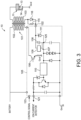
- Fig. 3 is a circuit diagram illustrating a configuration of the ignition circuit 10.
- the ignition circuit 10 includes an ignition coil 101 which applies voltage, particularly high voltage, for electric discharge to the spark plug 11, and optionally a coil driver 105 which realizes ON/OFF operation (or on and/or off operation, or intermittent operation) of electric current to the ignition coil 101.
- the coil driver 105 supplies the electric current to the ignition coil 101 and/or stops supplying the electric current to the ignition coil 101.
- the ignition coil 101 includes a primary coil 102 connected to a battery (not illustrated), and a secondary coil 103 connected to the center electrode 13 of the spark plug 11.
- the primary coil 102 and the secondary coil 103 may be wound around a common core (iron core).
- the coil driver 105 includes an igniter 106, and optionally a capacitor device 107, a current amplifier circuit 110, and a Zener diode 111.
- the igniter 106 may be a transistor interposed between the primary coil 102 and the ground (Gnd), and a collector may be connected to the primary coil 102 and an emitter is connected to the ground.
- the capacitor device 107 may be interposed between the secondary coil 103 and the ground.
- the Zener diode 111 may be electrically connected in parallel with the capacitor device 107.
- the current amplifier circuit 110 may be interposed between a terminal 121 connected to the ion current detector 44 of the ECU 40, and an negative-polarity-side terminal 125 of the capacitor device 107.
- a resistance 115 and a diode 116 which are connected in parallel to each other may be provided. That is, the secondary coil 103 may be connected to a terminal 122 of the coil driver 105 via the resistance 115 or the diode 116.
- the igniter 106 induces voltage, particularly high voltage, in the secondary coil 103 e.g., through ON/OFF (or on and/or off) of the electric current to the primary coil 102.
- the igniter 106 induces voltage, particularly high voltage, in the secondary coil 103 by intermitted electric current to the primary coil 102.
- the induced voltage, or high voltage causes electric discharge between the plug electrodes 13 and 14 of the spark plug 11.
- the igniter 106 may be switched to ON state before the ignition timing arrives. Therefore, the flow of the current between the collector and the emitter is permitted, and the current is given to the primary coil 102. That is, current which flows into the ground through the primary coil 102 and the igniter 106 from the battery occurs. Thus, when the ignition timing arrives, the igniter 106 may be switched from the ON state to the OFF state. Therefore, the flow of the current between the collector and the emitter is forbidden or interupt, and the current to the primary coil 102 is stopped. Thus, the electromagnetic induction accompanying the stop of the electric current induces in the secondary coil 103 high voltage according to a winding ratio of the secondary coil 103 to the primary coil 102.
- Fig. 4 is a view illustrating a flow of the current during the electric discharge (discharge current). As illustrated in this figure, the discharge current flows from the center electrode 13 of the spark plug 11 into the ground via the secondary coil 103, the diode 116, and the Zener diode 111.
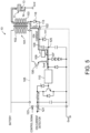
- the capacitor device 107 may apply to the spark plug 11 bias voltage for detecting the ion current. That is, ion or ions may be generated with the reaction of mixture gas inside of the cylinder 2 (i.e., the combustion chamber C).
- ion current occurs according to the potential difference between the plug electrodes 13 and 14 due to the bias voltage, as illustrated in Fig. 5 .
- the ion current flows toward the center electrode 13 of the spark plug 11 via the current amplifier circuit 110, the capacitor device 107, the resistance 115, and the secondary coil 103.
- the capacitor device 107 may function as a voltage supply source which applies to the spark plug 11 the bias voltage which leads to the generation of ion current, and is one example of a "bias voltage generator" of the present invention.
- the capacitor device 107 may include a capacitor 108 and a voltage control circuit 109 which may be electrically connected in parallel to each other.
- the capacitor 108 may have a pair of positive and negative polar plates which are chargeable.
- the voltage control circuit 109 may supply the electric charge to the capacitor 108 for the generation of the bias voltage described above. That is, when the electric charge is supplied from the voltage control circuit 109 and the capacitor 108 is charged, the potential difference occurs between the polar plates of the capacitor 108, the potential difference produces the potential difference also between the plug electrodes 13 and 14 of the spark plug 11, and it functions as the bias voltage.
- An amount of charge of the capacitor 108 (in other words, the bias voltage) may be fluctuated according to an amount of electric charge supplied from the voltage control circuit 109. In other words, the voltage control circuit 109 can control the bias voltage through the amount of electric charge supplied to the capacitor 108.
- the current amplifier circuit 110 may be a circuit which amplifies the ion current.
- the current amplified by the current amplifier circuit 110 may be detected by the ion current detector 44.
- the coil driver 105 may have a terminal 123 which accepts a control signal from the ignition controller 41 of the ECU 40.
- the igniter 106 and the capacitor device 107 (which includes the voltage control circuit 109) may operate in response to a control signal inputted through the terminal 123. That is, the ignition controller 41 may controls ON/OFF (or on and/or off) of the electric current to the primary coil 102 through the ON/OFF control of the igniter 106, and may control the bias voltage of the spark plug 11 through the adjustment of the amount of charge of the capacitor device 107 (capacitor 108).
- spark-ignition engine like this embodiment, there are needs to ignite mixture gas at a timing when thermal efficiency is as high as possible.
- knocking which is an abnormal combustion in which end gas (unburnt gas) carries out self-ignition in the middle of the combustion of mixture gas, may occur, if the ignition timing is not retarded from the timing at which the thermal efficiency is the highest.
- gasoline fuel used for spark-ignition engines mainly contains isooctane which is a component with high antiknocking capability.
- knocking may occur if the mixture gas is ignited at the normal ignition timing.
- octane number which is an index indicative of the antiknocking capability is often determined for vehicle-mount engines which appear in the market.
- the octane number may not be in agreement with the actual isooctane ratio (volume ratio). Thus, knocking may occur depending on the actual isooctane ratio.
- bio-fuel e.g., bioethanol
- synthetic fuel e.g., e-gasoline manufactured by synthesizing CO 2 and H 2 which is derived from reproducible energy
- bio-fuel and synthetic fuel are expected to be used as a mixture of the existing gasoline and additives especially during a spreading period.
- the ratio of isooctane may greatly fluctuate depending on the fuel used.
- the ratio of isooctane in the fuel used fluctuates at present and in future. Especially when the use of bio-fuel and synthetic fuel is considered, the ratio of isooctane may fluctuate greatly.
- the present inventors arrived at the idea of determining the ignition timing after estimating the ratio of isooctane contained in the fuel (hereinafter, also referred to as "the isooctane ratio") based on the ion current, paying attention to the correlation between the isooctane ratio and the ion current. That is, this is an idea of detecting the ion current before the spark plug 11 performing the ignition, calculating the isooctane ratio based on the detected ion current (eventually, calculating a given feature quantity (the maximum charge amount qmax which will be described later) indicative of the risk of knocking), and determining the ignition timing at the present cycle based on the calculated feature quantity. Below, this will be described in more detail.
- the ion current originates in ion or ions which are created by ionization of mixture gas containing evaporated and atomized fuel, it is expected that the difference in fuel properties appears as a difference in the ion current.
- an electric discharge simulation was performed to examine the correlation between the ion current and the isooctane ratio in fuel. That is, under various conditions with different isooctane ratios, virtual electric discharge was performed between the plug electrodes 13 and 14 using a model of the behavior of charged particles (ion or electron) between the plug electrodes 13 and 14, and the ion current which is created during the period up to the electric discharge was investigated.
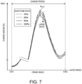
- a charge amount q which is a space charge between the plug electrodes 13 and 14 was identified, and a change in the charge amount q according to the isooctane ratio was investigated. Note that, as the charge amount q, an absolute value of the electronic space charge (negative) was used.
- Fig. 6 is a graph illustrating a change according to the crank angle in bias voltage applied to the plug electrodes 13 and 14 to produce the ion current.
- the change in the bias voltage is illustrated together with a charge signal which is an electric current signal to the primary coil 102.
- a first crank angle CA1 and a third crank angle CA3 in the horizontal axis of the graph are crank angles when starting and stopping the supply (charge) of the electric current to the primary coil 102, respectively. That is, a period from the first crank angle CA1 to the third crank angle CA3 is a charge period during which current is supplied to the primary coil 102.
- the stop of power supply (charge) to the primary coil 102 supplies the electric discharge between the plug electrodes 13 and 14, the end time of the charge period, which is at the third crank angle CA3, is equivalent to the timing when the electric discharge is performed (i.e., equivalent to the ignition timing).
- the bias voltage was applied during a period from the start of the charge period to the end of the charge period. That is, the bias voltage was applied at the first crank angle CA1 at which the charge period begins, and the application of the bias voltage was stopped at the third crank angle CA3 at which the charge period ends. Further, in this verification experiment, the bias voltage was changed in a bell-shaped curve. That is, the bias voltage was increased gradually from the first crank angle CA1 to the second crank angle CA2 which is between the first crank angle CA1 and the third crank angle CA3, and the bias voltage was decreased gradually from the second crank angle CA2 to the third crank angle CA3. In other words, in this verification experiment, the bias voltage was applied so that the voltage changes along a bell-shaped curve having a peak near the center of the charge period.
- the charge amount q changes in accordance with the bell-shaped curve having a peak in the middle of the charge period, similarly to the bias voltage. Further, the maximum charge amount qmax which is a value of the peak (i.e., the maximum value of the charge amount q) changes according to the isooctane ratio. That is, as being clear from Fig. 7 , the maximum charge amount qmax decreases as the isooctane ratio increases.
- Fig. 8 is a graph directly illustrating a relationship between the isooctane ratio and the maximum charge amount qmax which are obtained from the results of Fig. 7 .
- the maximum charge amount qmax decreases as the isooctane ratio increases, and increases as the isooctane ratio decreases.
- the large isooctane ratio means that knocking cannot easily occur
- the small isooctane ratio means that knocking can easily occur. This suggests that the ignition timing in consideration of knocking can be determined based on the maximum charge amount qmax.
- a standard ignition timing Igr which is determined based on an engine operating state is corrected according to the isooctane ratio estimated from the maximum charge amount qmax which is the feature quantity of the ion current, and mixture gas is ignited at the corrected ignition timing.
- Igr which is determined based on an engine operating state is corrected according to the isooctane ratio estimated from the maximum charge amount qmax which is the feature quantity of the ion current
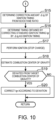
- Figs. 9 and 10 are flowcharts illustrating the details of the combustion control executed by the ECU 40 while the engine operates.
- the estimator 43 of the ECU 40 may acquire variety of information on the engine (Step S 1). Particularly, the estimator 43 acquires information on the crank angle, the engine speed, the intake air flow rate, the vehicle speed, and the accelerator opening from the detection values of the crank angle sensor SN1, the air flow sensor SN2, the vehicle speed sensor SN3, and the accelerator sensor SN4. Further, based on the accelerator opening and vehicle speed which are acquired, the ECU 40 may identify the engine load (demand torque).
- the estimator 43 may determine the injection amount and the injection timing of fuel (Step S2). That is, the estimator 43 may determine the injection amount which is an amount of fuel to be injected from the injector 15 based on the intake air flow rate and the engine load which are acquired at Step S1. The estimator 43 may determine the injection timing which is a timing at which the injection of fuel from the injector 15 is to be started based on the determined injection amount and the engine speed acquired at Step S 1.
- the estimator 43 may determine the standard ignition timing Igr based on the operating condition including the engine load and the engine speed which are acquired at Step S 1 (Step S3).
- the standard ignition timing Igr is defined in advance based on prior experiments for every engine operating condition as an ignition timing at which the thermal efficiency is maximized within a range in which knocking does not occur.
- the standard ignition timing Igr may be defined on the assumption that the isooctane ratio of fuel is a given reference value. Although the reference value of the isooctane ratio may be set suitably, it may be within a range of 90 to 100%, for example, taking the current commercially-available regular gasoline or high-octane gasoline into consideration.
- the memory 45B of the ECU 40 may store in advance map data which defines a relationship between the standard ignition timing Igr and the engine operating condition (load, engine speed, etc.) to derive the standard ignition timing Igr based on the engine operating condition.
- the estimator 43 may determine the standard ignition timing Igr from the engine operating condition by referring to the stored map data. Note that the data stored in the memory 45B to derive the standard ignition timing Igr may be an arithmetic expression, without being limited to the map data.
- the estimator 43 may estimate a start timing of the oxidation reaction, particularly low-temperature oxidation reaction, which is caused with compression of mixture gas (Step S4).
- the low-temperature oxidation reaction may be caused at e.g., 600 K to 800 K or about 600 K to about 800 K.
- the low-temperature oxidation reaction is slow oxidation reaction which occurs before a high-temperature oxidation reaction (substantial combustion reaction) which generates high thermal energy accompanied by flame, and it occurs in the second half of compression stroke when the combustion chamber C reaches a high temperature.
- the start timing of the low-temperature oxidation reaction may be estimated from the engine operating condition based on prior experiments etc.
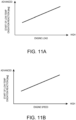
- Fig. 11A is a graph illustrating a relationship between the engine load and the start timing of the low-temperature oxidation reaction
- Fig. 11B is a graph illustrating a relationship between the engine speed and the start timing of the low-temperature oxidation reaction.
- Conditions other than the parameter of the horizontal axis are the same in these graphs.
- the low-temperature oxidation reaction is started at a timing on the advancing side as the engine load increases.
- Fig. 11B the low-temperature oxidation reaction is started at a timing on the advancing side as the engine speed increases.
- the memory 45B stores in advance the map data or the arithmetic expression corresponding to Figs. 11A and 11B .
- the estimator 43 estimates the start timing of the low-temperature oxidation reaction from the engine operating condition (load, engine speed, etc.) using the stored map data or arithmetic expression.
- the estimator 43 may determine a charge start timing which is a timing to start the supply of the electric current to the primary coil 102 of the ignition circuit 10 (i.e., to start the charge) (Step S5).
- the charge start timing is set to be substantially at the same timing as the start of the low-temperature oxidation reaction.
- the estimator 43 may determine the charge start timing based on the start timing of the low-temperature oxidation reaction estimated at Step S4 so that the charge is started at such a timing.
- the injection controller 42 of the ECU 40 may make the injector 15 inject fuel at a timing when the injection timing determined at Step S2 arrives (Step S6).
- the fuel injection may be continued until an amount of fuel corresponding to the injection amount determined at Step S2 is injected.
- the ignition controller 41 of the ECU 40 may start applying the bias voltage to the spark plug 11, while starting the supply of the electric current to the primary coil 102 (i.e., starting the charge), at a timing when the charge start timing determined at Step S5 arrives (Step S7). That is, the ignition controller 41 may control the igniter 106 so that the supply of the electric current to the primary coil 102 is started at a timing when the charge start timing which occurs substantially at the same timing as the low-temperature oxidation reaction, and may control the capacitor device 107 (voltage control circuit 109) so that the bias voltage is applied to the plug electrodes 13 and 14 of the spark plug 11 at the same timing.
- the supply of the electric current to the primary coil 102 and the application of the bias voltage may be started at the same timing which coincides with the start of the low-temperature oxidation reaction.
- the bias voltage is applied at the same timing as the start of the low-temperature oxidation reaction, because of the necessity of knowing an increase tendency of ion in the cylinder 2 which increases with the start of the low-temperature oxidation reaction.
- the start timing of the low-temperature oxidation reaction may be on the advancing side (or may be advanced) as the engine load or the engine speed increases, as illustrated in Figs. 11A and 11B . From this, the timing when the application of the bias voltage is started at Step S7 may be set on the more advancing side (or may be more advanced) as the engine load or the engine speed increases.
- the bias voltage may be applied so that the voltage changes in the bell-shaped curve (see Fig. 6 ). That is, in this embodiment, the ignition controller 41 may apply the bias voltage so that the voltage decreases gradually after it increased gradually from the start to the end of the charge. In more detail, the ignition controller 41 may start the application of the bias voltage at the first crank angle CA1 corresponding to the charge start timing determined at Step S5, and may increase the bias voltage gradually from this timing. Further, the ignition controller 41 may adjust the bias voltage so that the voltage reaches the peak at the second crank angle CA2 which is near the center of the charge period, and the voltage gradually decreases toward the third crank angle CA3 at which the charge period ends.
- the charge end timing corresponding to the third crank angle CA3 (in other words, the ignition timing) may be changed (corrected) from the standard ignition timing Igr determined at Step S3 by processing of each step described later, the bias voltage is adjusted here under the assumption that the standard ignition timing Igr is the charge end timing.
- the estimator 43 may determine whether a detection end timing CAx, which is slightly later than the peak period of the bias voltage (second crank angle CA2), has arrived (Step S8).
- the detection end timing CAx may be a timing at which the data of ion current necessary for calculating the maximum charge amount qmax at the following Step S9 is expected to be all gathered, and it may be set as a timing retarded by a given crank angle, particularly a given small crank angle, from the second crank angle CA2 at which the bias voltage reaches a peak.
- the period from the first crank angle CA1 at which the application of the bias voltage is started to the detection end timing CAx may be a detection period of the ion current necessary for calculating the maximum charge amount qmax.
- the estimator 43 may determine whether ignition of the mixture gas is detected based on the ion current detected by the ion current detector 44 of the ECU 40 (Step S12). If the mixture gas is ignited in this stage, it means that abnormal combustion in which mixture gas carries out a self-ignition before the ignition by the spark plug 11 (i.e., preignition) has occurred. An occurrence of a preignition (i.e., the self-ignition of the mixture gas during the charge period) appears as a phenomenon in which the ion current goes up at an abnormal increasing rate.
- the estimator 43 may determine that the preignition has occurred. Note that the estimator 43 which determines the occurrence of the preignition may correspond to an "abnormal combustion determinator" in the present invention.
- the injection controller 42 may make the injector 15 inject additional fuel (Step S13). That is, the injection controller 42 may make the injector 15 inject a small amount of additional fuel once finished with the injection of the predefined amount of fuel at Step S6.
- the injected additional fuel plays a role of causing a temperature drop by latent heat of vaporization to slow down the progress of combustion.
- the estimator 43 may return to Step S8, where it waits until the detection end timing CAx arrives.
- the estimator 43 may calculate the maximum charge amount qmax which is the maximum value of the charge amount q between the plug electrodes 13 and 14 based on the ion current detected by the ion current detector 44 so far (Step S9). Concretely, the estimator 43 may calculate the maximum charge amount qmax using the given arithmetic expression based on the data of the ion current detected by the ion current detector 44 during the detection period ( Fig. 6 ) from the first crank angle CA1 which is the application start timing of the bias voltage to the detection end timing CAx, and the data of the bias voltage during the same period. The maximum charge amount qmax calculated in this way can be considered as one of the values which characterize the ion current during the detection period (i.e., the ion current feature quantity).
- the detection end timing CAx is a timing which is somewhat retarded from the second crank angle CA2 ( Fig. 6 ) at which the bias voltage reaches a peak.
- the charge amount q between the plug electrodes 13 and 14 changes in accordance with the bell-shaped curve substantially similar to the tendency of the bias voltage. Therefore, at the timing of Step S9 which is immediately after the detection end timing CAx, it should have already passed the timing at which the charge amount q between the plug electrodes 13 and 14 reaches the maximum. That is, in this embodiment, the detection end timing CAx is set at the timing which is slightly later than a timing at which the charge amount q is estimated to be the maximum. Thus, even at the timing of Step S9 which is in the middle of the application of the bias voltage, the maximum charge amount qmax which is the maximum value of the charge amount q can be calculated.
- the estimator 43 may estimate the isooctane ratio of fuel based on the maximum charge amount qmax calculated at Step S9 (Step S10).
- the isooctane ratio is the ratio of isooctane contained in the fuel injected into the cylinder 2, and is defined with the tendency as illustrated in Fig. 8 based on the relationship with the maximum charge amount qmax. That is, the isooctane ratio decreases as the maximum charge amount qmax increases.
- the memory 45B stores in advance the map data or the arithmetic expression corresponding to Fig. 8 for every operating condition including the engine load and the engine speed.
- the estimator 43 may estimate the isooctane ratio from the maximum charge amount qmax using the map data or the arithmetic expression which suits the present operating condition.
- the estimator 43 may determine a correction amount ⁇ Ig of the standard ignition timing Igr from the isooctane ratio estimated at Step S10 (Step S 15).
- the correction amount ⁇ Ig may be set according to a deviating amount of the estimate value of the isooctane ratio obtained at Step S10 from a reference value which is a hypothetical isooctane ratio for setting the standard ignition timing Igr.
- the correction amount ⁇ Ig may be set larger as the deviating amount of the estimate value from the reference value increases.
- the correcting direction by the correction amount ⁇ Ig may change according to a magnitude relationship between the estimate value and the reference value of the isooctane ratio. For example, if the estimate value of the isooctane ratio is smaller than the reference value, the fuel in which knocking occurs more easily than expected is used. Therefore, the correction amount ⁇ Ig in this case may serve as a retard correction amount for correcting the standard ignition timing Igr toward the retarding side. On the other hand, if the estimate value of the isooctane ratio is larger than the reference value, the fuel with high antiknocking capability is used. Therefore, the correction amount ⁇ Ig in this case may serve as an advancing correction amount for correcting the standard ignition timing Igr toward the advancing side. Note that, if the reference value of the isooctane ratio is a value near 100%, fundamentally all the correction amounts ⁇ Ig become the retard correction amount.
- the ignition controller 41 may determine the timing which is obtained by correcting the standard ignition timing Igr by the ⁇ Ig determined at Step S15 as the ignition timing by the spark plug 11 (Step S16).
- the ignition timing determined in this way may be set with the tendency as illustrated in Fig. 12 according to the setting method of the correction amount ⁇ Ig described above. As illustrated in Fig.
- the ignition timing Igr determined at Step S16 (i.e., the corrected ignition timing obtained by correcting the standard ignition timing Igr by ⁇ Ig) may be set on the retarding side (or may be retarded) as the isooctane ratio decreases, and it may be set on the advancing side (or may be advanced) as the isooctane ratio increases.
- the ignition controller 41 may make the spark plug 11 perform ignition when the ignition timing determined at Step S16 (i.e., the timing obtained by correcting the standard ignition timing Igr by ⁇ Ig) arrives (Step S17). That is, the ignition controller 41 may control the igniter 106 so that the supply (charge) of the electric current to the primary coil 102 is stopped as the ignition timing arrives. Therefore, the voltage, particularly the high voltage, is induced in the secondary coil 103, and the electric discharge is performed between the plug electrodes 13 and 14 of the spark plug 11 in response to the induced high voltage.
- the estimator 43 may estimates a combustion center of gravity of the combustion caused by the ignition at Step S17 (Step S18).
- the combustion center of gravity is a timing when 50% by mass of the injected fuel is burnt.
- Such a combustion center of gravity may be estimated, for example, through calculation of an amount of heat release accompanying the combustion.
- the method of calculating the amount of heat release is not limited in particular. However, for example, if the engine is provided with an in-cylinder pressure sensor for detecting an in-cylinder pressure which is a pressure of the combustion chamber C, the amount of heat release may be calculated from a detection value of the in-cylinder pressure sensor, and the combustion center of gravity may be estimated from a change in the calculated amount of heat release.
- the estimator 43 may determines whether the combustion center of gravity estimated at Step S18 is deviated from a target combustion center of gravity (Step S19).
- the target combustion center of gravity may be defined in advance for every operating condition including the engine load and the engine speed, and may be stored in the memory 45B.
- the estimator 43 compares the combustion center of gravity estimated at Step S18 with the stored target combustion center of gravity, and determines whether there is a deviation therebetween.
- the ignition controller 41 may correct the standard ignition timing Igr according to the deviation (Step S20). For example, if the estimated combustion center of gravity is deviated toward the retarding side from the target combustion center of gravity, the ignition controller 41 may correct the standard ignition timing Igr toward the advancing side. On the contrary, if the estimated combustion center of gravity is deviated on the advancing side from the target combustion center of gravity, the ignition controller 41 may correct the standard ignition timing Igr toward the retarding side.
- the ignition controller 41 does not correct the standard ignition timing Igr, and may return the processing back to Step S 1.
- the bias voltage may be applied to the plug electrodes 13 and 14 of the spark plug 11 at the same timing as the start of the low-temperature oxidation reaction, and the ratio of isooctane contained in fuel (that is, the isooctane ratio) may be estimated based on the ion current detected during the detection period from the timing at which the application of the bias voltage is started (CA1) to the detection end timing CAx before the ignition timing (CA3). Then, the ignition timing in the same cycle as that when the estimation is performed may be corrected according to the isooctane ratio, and ignition by the spark plug 11 may be performed at the corrected ignition timing. According to such a configuration, there is an advantage that the occurrence of knocking can be prevented in advance, while improving the thermal efficiency.
- the ignition timing can be adjusted to the suitable timing in consideration of the difference in the isooctane ratio.
- the isooctane ratio is one of the typical fuel properties which influence on the risk of knocking. Therefore, according to this embodiment in which the ignition timing is corrected based on the isooctane ratio, the ignition timing can be set on the advancing side as the isooctane ratio increases, and the mixture gas can be ignited at the ignition timing at which the thermal efficiency is as high as possible, within the range where knocking does not occur.
- the ignition timing in the same cycle as that when the estimation is performed can be adjusted in advance to the suitable timing in consideration of knocking. Therefore, the occurrence of knocking can be prevented in advance, while improving the thermal efficiency.
- the maximum charge amount qmax which is the maximum value of the charge amount q (space charge) between the plug electrodes 13 and 14 during the detection period may be calculated, and the isooctane ratio may be estimated to be larger as the calculated maximum charge amount qmax decreases (see Fig. 8 ).
- the isooctane ratio can be estimated appropriately using the correlation between the maximum charge amount qmax and the isooctane ratio.
- the bias voltage may be adjusted so that, during application of the bias voltage, the voltage decreases gradually after it increased gradually (see Fig. 6 ).
- the charge amount q between the plug electrodes 13 and 14 can be changed in a similar bell-shaped curve. This makes it easier to calculate the maximum charge amount qmax which is the maximum value of the charge amount q.
- the ion current which increases with the start of the low-temperature oxidation reaction is further amplified by the gradual increase of the bias voltage, sensitivity of the maximum charge amount qmax which changes with the difference of the isooctane ratio can be improved. Therefore, the estimation precision of the isooctane ratio can be improved.
- the capacitor device 107 ( Fig. 3 ) may be connected to the secondary coil 103, and the bias voltage may be applied to the plug electrodes 13 and 14 by the static charge of the capacitor device 107. According to such a configuration, the bias voltage can be controlled appropriately by adjusting the amount of charge of the capacitor device 107.
- the application start timing of the bias voltage may be adjusted so that it is advanced as the engine load or the engine speed increases.
- the bias voltage can be applied at the same timing as the start of the low-temperature oxidation reaction which is advanced as the engine load or the engine speed increases (see Figs. 11A and 11B ), and the ion current which increases with the start of the low-temperature oxidation reaction can be detected appropriately.
- the occurrence of the preignition may be determined based on the detected ion current, and the additional fuel may be injected if the occurrence of the preignition is determined.
- the additional fuel since the latent heat of vaporization of the additionally-injected fuel lowers an internal temperature of the cylinder 2, the progress of combustion of mixture gas can be slowed down to reduce the influence of the preignition.
- the maximum charge amount qmax which is the maximum value of the charge amount q (space charge) between the plug electrodes 13 and 14 is calculated as the ion current feature quantity which correlates with the isooctane ratio
- the ion current feature quantity is not limited to the maximum charge amount qmax, as long as it is a value which can be calculated from the ion current detected by the ion current detector 44 and correlates with the isooctane ratio.
- the maximum ion current which is the maximum value of the ion current detected by the ion current detector 44 may be calculated as the ion current feature quantity.
- the isooctane ratio can be estimated from the calculated maximum ion current. That is, it can be estimated that the isooctane ratio is larger as the maximum ion current decreases.
- the isooctane ratio of fuel is estimated from the ion current (or the ion current feature quantity) detected during the given detection period
- the target to be estimated is not limited to the isooctane ratio, as long as it is a fuel property relevant to the risk of knocking.
- the supply (charge) of the electric current to the primary coil 102 and the application of the bias voltage to the plug electrodes 13 and 14 are started simultaneously, they may be started at different timings. That is, the bias voltage may be applied to the plug electrodes 13 and 14 at the same timing as the start of the low-temperature oxidation reaction, while the supply of the electric current to the primary coil 102 may be started at a timing somewhat earlier or later than the application start of the bias voltage.
Landscapes
- Engineering & Computer Science (AREA)
- Chemical & Material Sciences (AREA)
- Combustion & Propulsion (AREA)
- Mechanical Engineering (AREA)
- General Engineering & Computer Science (AREA)
- Physics & Mathematics (AREA)
- Plasma & Fusion (AREA)
- Signal Processing (AREA)
- Combined Controls Of Internal Combustion Engines (AREA)
- Ignition Installations For Internal Combustion Engines (AREA)
- Electrical Control Of Ignition Timing (AREA)
Abstract
Description
- The present invention relates to a combustion control system which is applied to an engine provided with a cylinder and a spark plug which ignites a mixture gas inside the cylinder.
- A combustion control device of an engine is disclosed in
JP5888773B2 JP5888773B2 - When the occurrence of the preignition is determined, the combustion control system of
JP5888773B2 - Therefore, the present invention is made in view of the above problems, and it aims at providing a combustion control system of an engine, capable of suppressing an occurrence of abnormal combustion in advance, while improving thermal efficiency of the engine.
- The above problem is solved by the present invention as defined in
claim 1. Particularly, a combustion control system is to be applied to an engine provided with a cylinder, an injector configured to inject fuel into the cylinder, and a spark plug configured to ignite a mixture gas containing the fuel injected from the injector. The combustion control system includes an ignition coil including a primary coil and a secondary coil, an igniter which induces voltage, particularly high voltage (e.g., 1500 V to 30000 V or about 1500 V to about 30000 V), in the secondary coil particularly through ON/OFF of supply of electric current to the primary coil, and causes electric discharge between plug electrodes of the spark plug by the induced voltage, e.g., the induced high voltage, and a bias voltage generator which applies bias voltage for detecting ion current to the plug electrodes, the ion current occurring between the plug electrodes and originating in ions inside the cylinder. The combustion control system may further include an ion current detector which detects the ion current, an ignition controller which controls the bias voltage generator to apply the bias voltage to the plug electrodes at a same timing as a start of an oxidation reaction, particularly a low-temperature oxidation reaction, caused inside the cylinder with compression of the mixture gas, and controls the igniter to cause the electric discharge between the plug electrodes at an ignition timing set to a timing later than the start of the oxidation reaction , particularly the low-temperature oxidation reaction, and an estimator which estimates a property of the fuel injected from the injector based on the ion current detected by the ion current detector during a detection period from a timing at which the application of the bias voltage is started to a given timing earlier than the ignition timing. The ignition controller corrects the ignition timing according to the property of the fuel, in the same cycle as that when the property of the fuel is estimated, and controls the igniter to perform the electric discharge at the corrected ignition timing. Particularly, the combustion control system includes a control unit configured to detect the ion current. The control unit is further configured to control the bias voltage generator to apply the bias voltage to the plug electrodes at a same timing as a start of an oxidation reaction, particularly a low-temperature oxidation reaction, caused inside the cylinder with compression of the mixture gas. The control unit is further configured to control the igniter to cause the electric discharge between the plug electrodes at an ignition timing set to a timing later than the start of the low-temperature oxidation reaction. The control unit is further configured to estimate a property of the fuel injected from the injector based on the ion current detected during a detection period from a timing at which the application of the bias voltage is started to a given timing earlier than the ignition timing. The control unit is further configured to correct the ignition timing according to the property of the fuel, in the same cycle as that when the property of the fuel is estimated. The control unit is further configured to control the igniter to perform the electric discharge at the corrected ignition timing. - According to the present invention, since the property of the fuel (hereinafter, also referred to as "the fuel property") is estimated based on the ion current detected before the ignition timing, and the ignition timing is corrected according to the estimated fuel property, the ignition timing can be adjusted to a suitable timing in consideration of a difference in the fuel property. In other words, since the difference in the fuel property influences a risk of knocking, according to the present invention in which the ignition timing is corrected based on the fuel property, mixture gas can be ignited at the ignition timing at which the thermal efficiency is as high as possible, within a range where knocking does not occur. In addition, since the fuel property is estimated before the ignition timing, the ignition timing in the same cycle as that when the estimation is performed can be adjusted in advance to the suitable timing in consideration of knocking. Therefore, knocking can be prevented in advance, while improving the thermal efficiency.
- The estimator or the control unit may estimate a ratio of isooctane contained in the fuel as the property of the fuel. The ignition controller or the control unit may correct the ignition timing toward a retarding side as the ratio of isooctane decreases. Particularly, the ignition controller or the control unit may retard the ignition timing as the ratio of isooctane decreases.
- The ratio of isooctane contained in the fuel (hereinafter, also referred to as "the isooctane ratio") is one of the typical fuel properties which influence on the risk of knocking. In detail, a large isooctane ratio means that knocking cannot easily occur, and a small isooctane ratio means that knocking can easily occur. Therefore, according to an embodiment in which the ignition timing is corrected toward the retarding side as the isooctane ratio decreases, knocking due to the fuel property can be suppressed effectively. Conversely, when the isooctane ratio is large, the ignition timing is set toward the advancing side. Therefore, the thermal efficiency can be improved while suppressing knocking.
- The estimator or the control unit may calculate an ion current feature quantity correlating with the property of the fuel, based on the ion current detected during the detection period, and estimate the ratio of isooctane from the calculated ion current feature quantity.
- According to this configuration, since the ion current feature quantity correlating with the isooctane ratio is calculated based on the ion current detected during the detection period, the isooctane ratio can be estimated appropriately from the ion current feature quantity.
- The ion current feature quantity may be a maximum charge amount that is a maximum value of a charge amount between the plug electrodes during the detection period, and the estimator or the control unit may estimate the ratio of isooctane to be larger as the maximum charge amount decreases.
- According to this configuration, the isooctane ratio can be estimated appropriately based on the maximum charge amount, by using the finding that the isooctane ratio increases as the maximum charge amount decreases.
- The ion current feature quantity may be a maximum ion current that is a maximum value of the ion current during the detection period. In this case, the estimator or the control unit may estimate the ratio of isooctane to be larger as the maximum ion current decreases.
- Also according to this configuration, the isooctane ratio can be estimated appropriately.
- The ignition controller or the control unit may control the bias voltage generator so that the bias voltage increases gradually from the start of the low-temperature oxidation reaction and decreases gradually thereafter.
- When the bias voltage is changed, particularly in a bell-shaped curve, in this way, the charge amount between the plug electrodes can be changed particularly in a similar bell-shaped curve. This makes it easier to calculate the above-described maximum charge amount which is the maximum value of the charge amount, or the above-described maximum ion current which is the maximum value of the ion current. Further, since the ion current which increases with the start of the low-temperature oxidation reaction is further amplified by the gradual increase of the bias voltage, sensitivity of the maximum charge amount or the maximum ion current which changes with the difference of the isooctane ratio can be improved. Therefore, the estimation precision of the isooctane ratio can be improved.
- The bias voltage generator may be a capacitor device connected to the secondary coil.
- According to this configuration, the bias voltage can be controlled appropriately by adjusting the charge amount of the capacitor device.
- The ignition controller or the control unit may control the bias voltage generator so that the application start of the bias voltage is advanced as an engine speed increases.
- Alternatively, the ignition controller or the control unit may control the bias voltage generator so that the application start of the bias voltage is advanced as an engine load increases.
- According to these configuration, the bias voltage can be applied at the same timing as the start of the oxidation reaction, particularly the low-temperature oxidation reaction, which is advanced as the engine load or the engine speed increases, and the ion current which increases with the start of the low-temperature oxidation reaction can be detected appropriately.
- The combustion control system may further include an abnormal combustion determinator which determines an occurrence of a preignition based on the ion current detected by the ion current detector, and an injection controller which causes the injector to inject additional fuel when the occurrence of the preignition is determined. Particularly, the estimator or the control unit is further configured to determine an occurrence of a preignition based on the ion current detected by the ion current detector, and the control unit is further configured to cause the injector to inject additional fuel when the occurrence of the preignition is determined.
- According to this configuration, since a latent heat of vaporization of the additionally-injected fuel lowers an internal temperature of the cylinder, the progress of combustion of mixture gas can be slowed down to reduce the influence of the preignition.
-
-
Fig. 1 is a system chart illustrating the overall configuration of an engine to which a combustion control system according to one embodiment of the present invention is applied. -
Fig. 2 is a view of a spark plug, where a tip-end part thereof is enlarged. -
Fig. 3 is a circuit diagram illustrating a configuration of an ignition circuit. -
Fig. 4 is a view corresponding toFig. 3 , illustrating a flow of discharge current. -
Fig. 5 is a view corresponding toFig. 3 , illustrating a flow of ion current. -
Fig. 6 is a graph illustrating a waveform of bias voltage applied to plug electrodes, together with a charge signal. -
Fig. 7 is a graph illustrating a change in a charge amount between the plug electrodes in conditions with different isooctane ratios of fuel. -
Fig. 8 is a graph illustrating a relationship between the isooctane ratio and the maximum charge amount. -
Fig. 9 is a flowchart illustrating the first half of a combustion control executed while the engine operates. -
Fig. 10 is flowchart illustrating the second half of the combustion control. -
Fig. 11A is a graph illustrating a relationship between an engine load and a start timing of a low-temperature oxidation reaction. -
Fig. 11B is a graph illustrating a relationship between an engine speed and the start timing of the low-temperature oxidation reaction. -
Fig. 12 is a graph illustrating a relationship between the isooctane ratio and a corrected ignition timing. -
Fig. 1 is a system chart illustrating the entire configuration of an engine or an engine system to which a combustion control system according to one embodiment of the present invention is applied. The engine illustrated in this figure is a spark-ignition four-cycle engine mounted on a vehicle as a power source for propelling the vehicle. The engine or the engine system includes the engine (engine body or engine 1), anintake passage 20 and anexhaust passage 30 connected to theengine 1, and an ECU (Electric Control Unit or Engine Control Unit) 40 which controls each part of theengine 1. Note that, although in this embodiment "up" and "down" are defined on the basis ofFig. 1 , this is for facilitating the following explanation and does not intend to limit the installation posture of theengine 1. - The
engine 1 may include acylinder block 3 and acylinder head 4 which define acylinder 2 therein, and apiston 5 which is reciprocatably accommodated in thecylinder 2. A combustion chamber C is formed above thepiston 5. Note that, although only onecylinder 2 is illustrated inFig. 1 , theengine 1 may be a multiple-cylinder engine having a plurality ofcylinders 2. - An
ignition circuit 10, aspark plug 11, and aninjector 15 may be attached to thecylinder head 4. Theinjector 15 is an injection valve which may inject into the combustion chamber C fuel (e.g., gasoline) supplied from a fuel tank (not illustrated) through afuel feeding pipe 15a. Thespark plug 11 is a plug which may ignite mixture gas generated by mixing the fuel injected into the combustion chamber C from theinjector 15 with air. Theignition circuit 10 is a circuit which may applies voltage, particularly high voltage, for making thespark plug 11 generate sparks for ignition. When the mixture gas inside the combustion chamber C combusts, triggered by the ignition of thespark plug 11, thepiston 5 reciprocates in response to expansive force due to the combustion. -
Fig. 2 is a view illustrating thespark plug 11, where a tip-end part thereof is enlarged. As illustrated in this figure, thespark plug 11 may include aplug body 12, acenter electrode 13, and anearth electrode 14. Theplug body 12 may have a cylindrical shape extending along a cylinder axis X1 which is the center axis of thecylinder 2, and may be attached to thecylinder head 4 in a state where the tip-end part is exposed to the inside of the combustion chamber C. Thecenter electrode 13 may project downwardly from the center of the tip-end part of theplug body 12. Theearth electrode 14 may extend downwardly and may be bent in an L-shape at a location near the tip-end part of theplug body 12. The tip end of theearth electrode 14 may oppose to thecenter electrode 13 with a given gap G therebetween. - The
center electrode 13 may be connected to a secondary coil 103 (described later) of theignition circuit 10. Theearth electrode 14 may be connected to the ground via theplug body 12 and thecylinder head 4. When performing ignition, electric discharge is performed between thecenter electrode 13 and theearth electrode 14 by applying the high voltage to thecenter electrode 13 from theignition circuit 10. Thus, mixture gas is ignited by sparks generated by this electric discharge. Note that, below, thecenter electrode 13 and theearth electrode 14 may be comprehensively referred to as "theplug electrodes - As illustrated in
Fig. 1 , acrankshaft 9 which is an output shaft of theengine 1 may be disposed below thepiston 5. Thecrankshaft 9 may be rotatably supported by thecylinder block 3. The above-described reciprocating motion of thepiston 5 may be transmitted to thecrankshaft 9 via a crank mechanism including a connectingrod 7 to rotate thecrankshaft 9. - A crank angle sensor SN1 may be attached to the
cylinder block 3. The crank angle sensor SN1 may be a sensor for detecting a crank angle which is a turning angle of thecrankshaft 9, and/or an engine speed which is a rotational speed of thecrankshaft 9. - An
intake port 16 and/or anexhaust port 17 may be formed in thecylinder head 4. Theintake port 16 is a port which communicates the combustion chamber C with theintake passage 20. Theexhaust port 17 is a port which communicates the combustion chamber C with theexhaust passage 30. Anintake valve 18 and/or anexhaust valve 19 which may be interlocked with the rotation of thecrankshaft 9 to open and/or close theintake port 16 and theexhaust port 17, respectively, may be attached to thecylinder head 4. - The
intake passage 20 may be connected to one side surface of thecylinder head 4 to communicate with theintake port 16. Athrottle valve 21 which opens and/or closes to adjust a flow rate of intake air may be provided to theintake passage 20. An air flow sensor SN2 which detects a flow rate of the intake air may be provided at a position of theintake passage 20 upstream of thethrottle valve 21. - The
exhaust passage 30 may be connected to the other side surface of thecylinder head 4 to communicate with theexhaust port 17. A catalyst which removes hazardous components in exhaust gas (not illustrated) may be provided to theexhaust passage 30. - An
ECU 40 is a controller which may mainly include a microcomputer having aprocessor 45A (e.g., Central Processing Unit (CPU)) which performs various calculations, amemory 45B, such as a Read-Only Memory (ROM) and a Random Access Memory (RAM), and various kinds of input/output buses. TheECU 40 may accept input information from one or more sensors provided to theengine 1. For example, theECU 40 may be electrically connected to the crank angle sensor SN1 and/or the air flow sensor SN2. Information on the detection by the sensor(s) SN1 and/or SN2 (i.e., the crank angle, the engine speed, and/or the intake air flow rate) is sequentially inputted into theECU 40. - The
ECU 40 may also accept input information from one or more sensors provided to the vehicle. For example, theECU 40 may be electrically connected to a vehicle speed sensor SN3 and/or an accelerator sensor SN4 which are provided to the vehicle. The vehicle speed sensor SN3 is a sensor which may detect a traveling speed of the vehicle (i.e., a vehicle speed), and the accelerator sensor SN4 is a sensor which may detect an opening (or operation amount) of anaccelerator pedal 50 operated by a vehicle driver who operates the vehicle (i.e., an accelerator opening). The detection information of the sensors SN3 and/or SN4 (the vehicle speed and the accelerator opening) may be sequentially inputted into theECU 40. - The
ECU 40 controls each part of the engine by performing various calculations and determinations based on the input information from the one or more sensors SN1-SN4. For example, theECU 40 may be electrically connected to theignition circuit 10 and/or theinjector 15, and may suitably output a signal for controlling to each of them. - As for functional elements related to the control, the
ECU 40 has at least one of anignition controller 41, aninjection controller 42, anestimator 43, and an ioncurrent detector 44. Theignition controller 41 may be a software module which controls ignition operation of thespark plug 11 through an electrical power control to theignition circuit 10. Theinjection controller 42 may be a software module which controls injection operation of theinjector 15. Theestimator 43 may be a software control module which performs various calculations and determinations necessary for determining the contents of control by theignition controller 41 and/or theinjection controller 42. The ioncurrent detector 44 may be a software module which detects ion current which is created between theplug electrodes spark plug 11 based on the signal from theignition circuit 10. Thememory 45B may be a storage device which stores various data necessary for the control or the calculation. The various software modules may be stored in thememory 45B and executed by theprocessor 45A to perform their respective functions. -
Fig. 3 is a circuit diagram illustrating a configuration of theignition circuit 10. As illustrated in this figure, theignition circuit 10 includes anignition coil 101 which applies voltage, particularly high voltage, for electric discharge to thespark plug 11, and optionally acoil driver 105 which realizes ON/OFF operation (or on and/or off operation, or intermittent operation) of electric current to theignition coil 101. Particularly thecoil driver 105 supplies the electric current to theignition coil 101 and/or stops supplying the electric current to theignition coil 101. - The
ignition coil 101 includes aprimary coil 102 connected to a battery (not illustrated), and asecondary coil 103 connected to thecenter electrode 13 of thespark plug 11. Theprimary coil 102 and thesecondary coil 103 may be wound around a common core (iron core). - The
coil driver 105 includes anigniter 106, and optionally acapacitor device 107, acurrent amplifier circuit 110, and aZener diode 111. Theigniter 106 may be a transistor interposed between theprimary coil 102 and the ground (Gnd), and a collector may be connected to theprimary coil 102 and an emitter is connected to the ground. Thecapacitor device 107 may be interposed between thesecondary coil 103 and the ground. TheZener diode 111 may be electrically connected in parallel with thecapacitor device 107. Thecurrent amplifier circuit 110 may be interposed between a terminal 121 connected to the ioncurrent detector 44 of theECU 40, and an negative-polarity-side terminal 125 of thecapacitor device 107. - Between the
secondary coil 103 and thecoil driver 105, aresistance 115 and adiode 116 which are connected in parallel to each other may be provided. That is, thesecondary coil 103 may be connected to aterminal 122 of thecoil driver 105 via theresistance 115 or thediode 116. - The
igniter 106 induces voltage, particularly high voltage, in thesecondary coil 103 e.g., through ON/OFF (or on and/or off) of the electric current to theprimary coil 102. Particularly, theigniter 106 induces voltage, particularly high voltage, in thesecondary coil 103 by intermitted electric current to theprimary coil 102. The induced voltage, or high voltage, causes electric discharge between theplug electrodes spark plug 11. - Particularly, the
igniter 106 may be switched to ON state before the ignition timing arrives. Therefore, the flow of the current between the collector and the emitter is permitted, and the current is given to theprimary coil 102. That is, current which flows into the ground through theprimary coil 102 and theigniter 106 from the battery occurs. Thus, when the ignition timing arrives, theigniter 106 may be switched from the ON state to the OFF state. Therefore, the flow of the current between the collector and the emitter is forbidden or interupt, and the current to theprimary coil 102 is stopped. Thus, the electromagnetic induction accompanying the stop of the electric current induces in thesecondary coil 103 high voltage according to a winding ratio of thesecondary coil 103 to theprimary coil 102. - When the voltage, particularly the high voltage, is induced by the
secondary coil 103 as described above, electric discharge resulting from the high voltage occurs between theplug electrodes spark plug 11, and sparks are generated. The sparks ignite mixture gas inside the combustion chamber C.Fig. 4 is a view illustrating a flow of the current during the electric discharge (discharge current). As illustrated in this figure, the discharge current flows from thecenter electrode 13 of thespark plug 11 into the ground via thesecondary coil 103, thediode 116, and theZener diode 111. - The
capacitor device 107 may apply to thespark plug 11 bias voltage for detecting the ion current. That is, ion or ions may be generated with the reaction of mixture gas inside of the cylinder 2 (i.e., the combustion chamber C). When the bias voltage is applied to thespark plug 11 during the generation of ion, ion current occurs according to the potential difference between theplug electrodes Fig. 5 . The ion current flows toward thecenter electrode 13 of thespark plug 11 via thecurrent amplifier circuit 110, thecapacitor device 107, theresistance 115, and thesecondary coil 103. Thecapacitor device 107 may function as a voltage supply source which applies to thespark plug 11 the bias voltage which leads to the generation of ion current, and is one example of a "bias voltage generator" of the present invention. - The
capacitor device 107 may include acapacitor 108 and avoltage control circuit 109 which may be electrically connected in parallel to each other. Thecapacitor 108 may have a pair of positive and negative polar plates which are chargeable. Thevoltage control circuit 109 may supply the electric charge to thecapacitor 108 for the generation of the bias voltage described above. That is, when the electric charge is supplied from thevoltage control circuit 109 and thecapacitor 108 is charged, the potential difference occurs between the polar plates of thecapacitor 108, the potential difference produces the potential difference also between theplug electrodes spark plug 11, and it functions as the bias voltage. An amount of charge of the capacitor 108 (in other words, the bias voltage) may be fluctuated according to an amount of electric charge supplied from thevoltage control circuit 109. In other words, thevoltage control circuit 109 can control the bias voltage through the amount of electric charge supplied to thecapacitor 108. - The
current amplifier circuit 110 may be a circuit which amplifies the ion current. The current amplified by thecurrent amplifier circuit 110 may be detected by the ioncurrent detector 44. - The
coil driver 105 may have a terminal 123 which accepts a control signal from theignition controller 41 of theECU 40. Theigniter 106 and the capacitor device 107 (which includes the voltage control circuit 109) may operate in response to a control signal inputted through the terminal 123. That is, theignition controller 41 may controls ON/OFF (or on and/or off) of the electric current to theprimary coil 102 through the ON/OFF control of theigniter 106, and may control the bias voltage of thespark plug 11 through the adjustment of the amount of charge of the capacitor device 107 (capacitor 108). - Here, in the spark-ignition engine like this embodiment, there are needs to ignite mixture gas at a timing when thermal efficiency is as high as possible. However, depending on the property of fuel injected into the cylinder 2 (combustion chamber C), knocking, which is an abnormal combustion in which end gas (unburnt gas) carries out self-ignition in the middle of the combustion of mixture gas, may occur, if the ignition timing is not retarded from the timing at which the thermal efficiency is the highest. For example, gasoline fuel used for spark-ignition engines mainly contains isooctane which is a component with high antiknocking capability. However, as the ratio of isooctane changes, knocking may occur if the mixture gas is ignited at the normal ignition timing. Regarding this, a lower limit of the octane number which is an index indicative of the antiknocking capability is often determined for vehicle-mount engines which appear in the market. However, the octane number may not be in agreement with the actual isooctane ratio (volume ratio). Thus, knocking may occur depending on the actual isooctane ratio.
- Further, in recent years, from the viewpoint of carbon neutral, bio-fuel (e.g., bioethanol) manufactured from biomass, and synthetic fuel (e.g., e-gasoline manufactured by synthesizing CO2 and H2 which is derived from reproducible energy), attracts the attention. These bio-fuel and synthetic fuel are expected to be used as a mixture of the existing gasoline and additives especially during a spreading period. When the use of such various fuels is considered, the ratio of isooctane may greatly fluctuate depending on the fuel used.
- Thus, it is considered that in the spark-ignition engines the ratio of isooctane in the fuel used fluctuates at present and in future. Especially when the use of bio-fuel and synthetic fuel is considered, the ratio of isooctane may fluctuate greatly. In order to improve thermal efficiency, while permitting the use of the fuels with different properties, it is desired to ignite the mixture gas at a timing when thermal efficiency is as high as possible, while suppressing knocking by adjusting the ignition timing based on the fuel properties.
- Thus, the present inventors arrived at the idea of determining the ignition timing after estimating the ratio of isooctane contained in the fuel (hereinafter, also referred to as "the isooctane ratio") based on the ion current, paying attention to the correlation between the isooctane ratio and the ion current. That is, this is an idea of detecting the ion current before the
spark plug 11 performing the ignition, calculating the isooctane ratio based on the detected ion current (eventually, calculating a given feature quantity (the maximum charge amount qmax which will be described later) indicative of the risk of knocking), and determining the ignition timing at the present cycle based on the calculated feature quantity. Below, this will be described in more detail. - Since the ion current originates in ion or ions which are created by ionization of mixture gas containing evaporated and atomized fuel, it is expected that the difference in fuel properties appears as a difference in the ion current. Thus, as a verification experiment based on this expectation, an electric discharge simulation was performed to examine the correlation between the ion current and the isooctane ratio in fuel. That is, under various conditions with different isooctane ratios, virtual electric discharge was performed between the
plug electrodes plug electrodes plug electrodes -
Fig. 6 is a graph illustrating a change according to the crank angle in bias voltage applied to theplug electrodes primary coil 102. Further, a first crank angle CA1 and a third crank angle CA3 in the horizontal axis of the graph are crank angles when starting and stopping the supply (charge) of the electric current to theprimary coil 102, respectively. That is, a period from the first crank angle CA1 to the third crank angle CA3 is a charge period during which current is supplied to theprimary coil 102. As described above, since the stop of power supply (charge) to theprimary coil 102 supplies the electric discharge between theplug electrodes - As illustrated in
Fig. 6 , in this verification experiment, the bias voltage was applied during a period from the start of the charge period to the end of the charge period. That is, the bias voltage was applied at the first crank angle CA1 at which the charge period begins, and the application of the bias voltage was stopped at the third crank angle CA3 at which the charge period ends. Further, in this verification experiment, the bias voltage was changed in a bell-shaped curve. That is, the bias voltage was increased gradually from the first crank angle CA1 to the second crank angle CA2 which is between the first crank angle CA1 and the third crank angle CA3, and the bias voltage was decreased gradually from the second crank angle CA2 to the third crank angle CA3. In other words, in this verification experiment, the bias voltage was applied so that the voltage changes along a bell-shaped curve having a peak near the center of the charge period. - Next, the change in the charge amount q which is caused when the bias voltage is applied was examined as described above, and results were obtained as illustrated in
Fig. 7 . In detail, under the various conditions with the different isooctane ratios in fuel, the bias voltage which changes in the bell-shaped curve was applied to thespark plug 11 as illustrated inFig. 6 , and the change in the charge amount q at that time was investigated. Between the graphs inFig. 7 , conditions other than the isooctane ratio (for example, engine load and engine speed) are the same. - As illustrated in
Fig. 7 , the charge amount q changes in accordance with the bell-shaped curve having a peak in the middle of the charge period, similarly to the bias voltage. Further, the maximum charge amount qmax which is a value of the peak (i.e., the maximum value of the charge amount q) changes according to the isooctane ratio. That is, as being clear fromFig. 7 , the maximum charge amount qmax decreases as the isooctane ratio increases. -
Fig. 8 is a graph directly illustrating a relationship between the isooctane ratio and the maximum charge amount qmax which are obtained from the results ofFig. 7 . As is understood also from this graph, the maximum charge amount qmax decreases as the isooctane ratio increases, and increases as the isooctane ratio decreases. Here, the large isooctane ratio means that knocking cannot easily occur, and the small isooctane ratio means that knocking can easily occur. This suggests that the ignition timing in consideration of knocking can be determined based on the maximum charge amount qmax. - Next, details of an engine combustion control executed based on the knowledge described above are described. As illustrated below, in this embodiment, a standard ignition timing Igr which is determined based on an engine operating state is corrected according to the isooctane ratio estimated from the maximum charge amount qmax which is the feature quantity of the ion current, and mixture gas is ignited at the corrected ignition timing. In addition, since calculation for such an ignition timing determination is performed while supplying the electric current to the primary coil 102 (during the charge period), it is possible to correct the ignition timing within the same cycle as that when this calculation is performed. Below, this will be described in more detail.
-
Figs. 9 and10 are flowcharts illustrating the details of the combustion control executed by theECU 40 while the engine operates. When this combustion control starts, theestimator 43 of theECU 40 may acquire variety of information on the engine (Step S 1). Particularly, theestimator 43 acquires information on the crank angle, the engine speed, the intake air flow rate, the vehicle speed, and the accelerator opening from the detection values of the crank angle sensor SN1, the air flow sensor SN2, the vehicle speed sensor SN3, and the accelerator sensor SN4. Further, based on the accelerator opening and vehicle speed which are acquired, theECU 40 may identify the engine load (demand torque). - Subsequently, the
estimator 43 may determine the injection amount and the injection timing of fuel (Step S2). That is, theestimator 43 may determine the injection amount which is an amount of fuel to be injected from theinjector 15 based on the intake air flow rate and the engine load which are acquired at Step S1. Theestimator 43 may determine the injection timing which is a timing at which the injection of fuel from theinjector 15 is to be started based on the determined injection amount and the engine speed acquired atStep S 1. - Subsequently, the
estimator 43 may determine the standard ignition timing Igr based on the operating condition including the engine load and the engine speed which are acquired at Step S 1 (Step S3). The standard ignition timing Igr is defined in advance based on prior experiments for every engine operating condition as an ignition timing at which the thermal efficiency is maximized within a range in which knocking does not occur. Further, the standard ignition timing Igr may be defined on the assumption that the isooctane ratio of fuel is a given reference value. Although the reference value of the isooctane ratio may be set suitably, it may be within a range of 90 to 100%, for example, taking the current commercially-available regular gasoline or high-octane gasoline into consideration. - The
memory 45B of theECU 40 may store in advance map data which defines a relationship between the standard ignition timing Igr and the engine operating condition (load, engine speed, etc.) to derive the standard ignition timing Igr based on the engine operating condition. Theestimator 43 may determine the standard ignition timing Igr from the engine operating condition by referring to the stored map data. Note that the data stored in thememory 45B to derive the standard ignition timing Igr may be an arithmetic expression, without being limited to the map data. - Subsequently, the
estimator 43 may estimate a start timing of the oxidation reaction, particularly low-temperature oxidation reaction, which is caused with compression of mixture gas (Step S4). The low-temperature oxidation reaction may be caused at e.g., 600 K to 800 K or about 600 K to about 800 K. The low-temperature oxidation reaction is slow oxidation reaction which occurs before a high-temperature oxidation reaction (substantial combustion reaction) which generates high thermal energy accompanied by flame, and it occurs in the second half of compression stroke when the combustion chamber C reaches a high temperature. The start timing of the low-temperature oxidation reaction may be estimated from the engine operating condition based on prior experiments etc. -
Fig. 11A is a graph illustrating a relationship between the engine load and the start timing of the low-temperature oxidation reaction, andFig. 11B is a graph illustrating a relationship between the engine speed and the start timing of the low-temperature oxidation reaction. Conditions other than the parameter of the horizontal axis (engine load or engine speed) are the same in these graphs. As illustrated inFig. 11A , the low-temperature oxidation reaction is started at a timing on the advancing side as the engine load increases. Further, as illustrated inFig. 11B , the low-temperature oxidation reaction is started at a timing on the advancing side as the engine speed increases. Thememory 45B stores in advance the map data or the arithmetic expression corresponding toFigs. 11A and 11B . Theestimator 43 estimates the start timing of the low-temperature oxidation reaction from the engine operating condition (load, engine speed, etc.) using the stored map data or arithmetic expression. - Subsequently, the
estimator 43 may determine a charge start timing which is a timing to start the supply of the electric current to theprimary coil 102 of the ignition circuit 10 (i.e., to start the charge) (Step S5). In this embodiment, the charge start timing is set to be substantially at the same timing as the start of the low-temperature oxidation reaction. Theestimator 43 may determine the charge start timing based on the start timing of the low-temperature oxidation reaction estimated at Step S4 so that the charge is started at such a timing. - Subsequently, the
injection controller 42 of theECU 40 may make theinjector 15 inject fuel at a timing when the injection timing determined at Step S2 arrives (Step S6). The fuel injection may be continued until an amount of fuel corresponding to the injection amount determined at Step S2 is injected. - Subsequently, the
ignition controller 41 of theECU 40 may start applying the bias voltage to thespark plug 11, while starting the supply of the electric current to the primary coil 102 (i.e., starting the charge), at a timing when the charge start timing determined at Step S5 arrives (Step S7). That is, theignition controller 41 may control theigniter 106 so that the supply of the electric current to theprimary coil 102 is started at a timing when the charge start timing which occurs substantially at the same timing as the low-temperature oxidation reaction, and may control the capacitor device 107 (voltage control circuit 109) so that the bias voltage is applied to theplug electrodes spark plug 11 at the same timing. Thus, in this embodiment, the supply of the electric current to theprimary coil 102 and the application of the bias voltage may be started at the same timing which coincides with the start of the low-temperature oxidation reaction. The bias voltage is applied at the same timing as the start of the low-temperature oxidation reaction, because of the necessity of knowing an increase tendency of ion in thecylinder 2 which increases with the start of the low-temperature oxidation reaction. - Here, the start timing of the low-temperature oxidation reaction may be on the advancing side (or may be advanced) as the engine load or the engine speed increases, as illustrated in
Figs. 11A and 11B . From this, the timing when the application of the bias voltage is started at Step S7 may be set on the more advancing side (or may be more advanced) as the engine load or the engine speed increases. - Further, at Step S7, similarly to the verification experiment described above, the bias voltage may be applied so that the voltage changes in the bell-shaped curve (see
Fig. 6 ). That is, in this embodiment, theignition controller 41 may apply the bias voltage so that the voltage decreases gradually after it increased gradually from the start to the end of the charge. In more detail, theignition controller 41 may start the application of the bias voltage at the first crank angle CA1 corresponding to the charge start timing determined at Step S5, and may increase the bias voltage gradually from this timing. Further, theignition controller 41 may adjust the bias voltage so that the voltage reaches the peak at the second crank angle CA2 which is near the center of the charge period, and the voltage gradually decreases toward the third crank angle CA3 at which the charge period ends. Note that, although the charge end timing corresponding to the third crank angle CA3 (in other words, the ignition timing) may be changed (corrected) from the standard ignition timing Igr determined at Step S3 by processing of each step described later, the bias voltage is adjusted here under the assumption that the standard ignition timing Igr is the charge end timing. - Subsequently, the
estimator 43 may determine whether a detection end timing CAx, which is slightly later than the peak period of the bias voltage (second crank angle CA2), has arrived (Step S8). The detection end timing CAx may be a timing at which the data of ion current necessary for calculating the maximum charge amount qmax at the following Step S9 is expected to be all gathered, and it may be set as a timing retarded by a given crank angle, particularly a given small crank angle, from the second crank angle CA2 at which the bias voltage reaches a peak. In other words, the period from the first crank angle CA1 at which the application of the bias voltage is started to the detection end timing CAx may be a detection period of the ion current necessary for calculating the maximum charge amount qmax. - If it is determined to be NO at Step S8 and it is confirmed that the detection end timing CAx has not yet arrived, the
estimator 43 then may determine whether ignition of the mixture gas is detected based on the ion current detected by the ioncurrent detector 44 of the ECU 40 (Step S12). If the mixture gas is ignited in this stage, it means that abnormal combustion in which mixture gas carries out a self-ignition before the ignition by the spark plug 11 (i.e., preignition) has occurred. An occurrence of a preignition (i.e., the self-ignition of the mixture gas during the charge period) appears as a phenomenon in which the ion current goes up at an abnormal increasing rate. At Step S12, if the abnormal increase of the ion current is confirmed, theestimator 43 may determine that the preignition has occurred. Note that theestimator 43 which determines the occurrence of the preignition may correspond to an "abnormal combustion determinator" in the present invention. - If it is determined to be YES at Step S12 and the occurrence of the preignition is confirmed, the
injection controller 42 may make theinjector 15 inject additional fuel (Step S13). That is, theinjection controller 42 may make theinjector 15 inject a small amount of additional fuel once finished with the injection of the predefined amount of fuel at Step S6. The injected additional fuel plays a role of causing a temperature drop by latent heat of vaporization to slow down the progress of combustion. - On the other hand, if it is determined to be NO at Step S12 and it is confirmed that the preignition has not yet occurred, the
estimator 43 may return to Step S8, where it waits until the detection end timing CAx arrives. - If it is determined to be YES at Step S8 and it is confirmed that the detection end timing CAx has arrived, the
estimator 43 may calculate the maximum charge amount qmax which is the maximum value of the charge amount q between theplug electrodes current detector 44 so far (Step S9). Concretely, theestimator 43 may calculate the maximum charge amount qmax using the given arithmetic expression based on the data of the ion current detected by the ioncurrent detector 44 during the detection period (Fig. 6 ) from the first crank angle CA1 which is the application start timing of the bias voltage to the detection end timing CAx, and the data of the bias voltage during the same period. The maximum charge amount qmax calculated in this way can be considered as one of the values which characterize the ion current during the detection period (i.e., the ion current feature quantity). - Here, as described above, the detection end timing CAx is a timing which is somewhat retarded from the second crank angle CA2 (
Fig. 6 ) at which the bias voltage reaches a peak. On the other hand, as understood fromFigs. 6 and7 , the charge amount q between theplug electrodes 13 and 14 (space charge) changes in accordance with the bell-shaped curve substantially similar to the tendency of the bias voltage. Therefore, at the timing of Step S9 which is immediately after the detection end timing CAx, it should have already passed the timing at which the charge amount q between theplug electrodes - Subsequently, the
estimator 43 may estimate the isooctane ratio of fuel based on the maximum charge amount qmax calculated at Step S9 (Step S10). As described above, the isooctane ratio is the ratio of isooctane contained in the fuel injected into thecylinder 2, and is defined with the tendency as illustrated inFig. 8 based on the relationship with the maximum charge amount qmax. That is, the isooctane ratio decreases as the maximum charge amount qmax increases. Thememory 45B stores in advance the map data or the arithmetic expression corresponding toFig. 8 for every operating condition including the engine load and the engine speed. Theestimator 43 may estimate the isooctane ratio from the maximum charge amount qmax using the map data or the arithmetic expression which suits the present operating condition. - Subsequently, the
estimator 43 may determine a correction amount ΔIg of the standard ignition timing Igr from the isooctane ratio estimated at Step S10 (Step S 15). The correction amount ΔIg may be set according to a deviating amount of the estimate value of the isooctane ratio obtained at Step S10 from a reference value which is a hypothetical isooctane ratio for setting the standard ignition timing Igr. In detail, the correction amount ΔIg may be set larger as the deviating amount of the estimate value from the reference value increases. - Further, the correcting direction by the correction amount ΔIg may change according to a magnitude relationship between the estimate value and the reference value of the isooctane ratio. For example, if the estimate value of the isooctane ratio is smaller than the reference value, the fuel in which knocking occurs more easily than expected is used. Therefore, the correction amount ΔIg in this case may serve as a retard correction amount for correcting the standard ignition timing Igr toward the retarding side. On the other hand, if the estimate value of the isooctane ratio is larger than the reference value, the fuel with high antiknocking capability is used. Therefore, the correction amount ΔIg in this case may serve as an advancing correction amount for correcting the standard ignition timing Igr toward the advancing side. Note that, if the reference value of the isooctane ratio is a value near 100%, fundamentally all the correction amounts ΔIg become the retard correction amount.
- Subsequently, the
ignition controller 41 may determine the timing which is obtained by correcting the standard ignition timing Igr by the ΔIg determined at Step S15 as the ignition timing by the spark plug 11 (Step S16). The ignition timing determined in this way may be set with the tendency as illustrated inFig. 12 according to the setting method of the correction amount ΔIg described above. As illustrated inFig. 12 , the ignition timing Igr determined at Step S16 (i.e., the corrected ignition timing obtained by correcting the standard ignition timing Igr by ΔIg) may be set on the retarding side (or may be retarded) as the isooctane ratio decreases, and it may be set on the advancing side (or may be advanced) as the isooctane ratio increases. - Subsequently, the
ignition controller 41 may make thespark plug 11 perform ignition when the ignition timing determined at Step S16 (i.e., the timing obtained by correcting the standard ignition timing Igr by ΔIg) arrives (Step S17). That is, theignition controller 41 may control theigniter 106 so that the supply (charge) of the electric current to theprimary coil 102 is stopped as the ignition timing arrives. Therefore, the voltage, particularly the high voltage, is induced in thesecondary coil 103, and the electric discharge is performed between theplug electrodes spark plug 11 in response to the induced high voltage. - Subsequently, the
estimator 43 may estimates a combustion center of gravity of the combustion caused by the ignition at Step S17 (Step S18). The combustion center of gravity is a timing when 50% by mass of the injected fuel is burnt. Such a combustion center of gravity may be estimated, for example, through calculation of an amount of heat release accompanying the combustion. The method of calculating the amount of heat release is not limited in particular. However, for example, if the engine is provided with an in-cylinder pressure sensor for detecting an in-cylinder pressure which is a pressure of the combustion chamber C, the amount of heat release may be calculated from a detection value of the in-cylinder pressure sensor, and the combustion center of gravity may be estimated from a change in the calculated amount of heat release. - Subsequently, the
estimator 43 may determines whether the combustion center of gravity estimated at Step S18 is deviated from a target combustion center of gravity (Step S19). The target combustion center of gravity may be defined in advance for every operating condition including the engine load and the engine speed, and may be stored in thememory 45B. Theestimator 43 compares the combustion center of gravity estimated at Step S18 with the stored target combustion center of gravity, and determines whether there is a deviation therebetween. - If it is determined to be YES at Step S19 and it is confirmed that there is a deviation of the combustion center of gravity, the
ignition controller 41 may correct the standard ignition timing Igr according to the deviation (Step S20). For example, if the estimated combustion center of gravity is deviated toward the retarding side from the target combustion center of gravity, theignition controller 41 may correct the standard ignition timing Igr toward the advancing side. On the contrary, if the estimated combustion center of gravity is deviated on the advancing side from the target combustion center of gravity, theignition controller 41 may correct the standard ignition timing Igr toward the retarding side. - On the other hand, if it is determined to be NO at Step S19 and it is confirmed that there is no deviation of the combustion center of gravity, the
ignition controller 41 does not correct the standard ignition timing Igr, and may return the processing back toStep S 1. - As described above, in this embodiment, the bias voltage may be applied to the
plug electrodes spark plug 11 at the same timing as the start of the low-temperature oxidation reaction, and the ratio of isooctane contained in fuel (that is, the isooctane ratio) may be estimated based on the ion current detected during the detection period from the timing at which the application of the bias voltage is started (CA1) to the detection end timing CAx before the ignition timing (CA3). Then, the ignition timing in the same cycle as that when the estimation is performed may be corrected according to the isooctane ratio, and ignition by thespark plug 11 may be performed at the corrected ignition timing. According to such a configuration, there is an advantage that the occurrence of knocking can be prevented in advance, while improving the thermal efficiency. - That is, in this embodiment, since the isooctane ratio of fuel can be estimated based on the ion current detected before the ignition timing, and the ignition timing is corrected according to the estimated isooctane ratio, the ignition timing can be adjusted to the suitable timing in consideration of the difference in the isooctane ratio. In detail, the isooctane ratio is one of the typical fuel properties which influence on the risk of knocking. Therefore, according to this embodiment in which the ignition timing is corrected based on the isooctane ratio, the ignition timing can be set on the advancing side as the isooctane ratio increases, and the mixture gas can be ignited at the ignition timing at which the thermal efficiency is as high as possible, within the range where knocking does not occur. In addition, since the isooctane ratio is estimated before the ignition timing, the ignition timing in the same cycle as that when the estimation is performed can be adjusted in advance to the suitable timing in consideration of knocking. Therefore, the occurrence of knocking can be prevented in advance, while improving the thermal efficiency.
- Particularly, in this embodiment, as the ion current feature quantity which correlates with the isooctane ratio, the maximum charge amount qmax which is the maximum value of the charge amount q (space charge) between the
plug electrodes Fig. 8 ). According to such a configuration, the isooctane ratio can be estimated appropriately using the correlation between the maximum charge amount qmax and the isooctane ratio. - In this embodiment, the bias voltage may be adjusted so that, during application of the bias voltage, the voltage decreases gradually after it increased gradually (see
Fig. 6 ). Thus, when the bias voltage is changed in the bell-shaped curve, the charge amount q between theplug electrodes - Further, in this embodiment, the capacitor device 107 (
Fig. 3 ) may be connected to thesecondary coil 103, and the bias voltage may be applied to theplug electrodes capacitor device 107. According to such a configuration, the bias voltage can be controlled appropriately by adjusting the amount of charge of thecapacitor device 107. - In this embodiment, the application start timing of the bias voltage may be adjusted so that it is advanced as the engine load or the engine speed increases. According to such a configuration, the bias voltage can be applied at the same timing as the start of the low-temperature oxidation reaction which is advanced as the engine load or the engine speed increases (see
Figs. 11A and 11B ), and the ion current which increases with the start of the low-temperature oxidation reaction can be detected appropriately. - In this embodiment, the occurrence of the preignition may be determined based on the detected ion current, and the additional fuel may be injected if the occurrence of the preignition is determined. According to such a configuration, since the latent heat of vaporization of the additionally-injected fuel lowers an internal temperature of the
cylinder 2, the progress of combustion of mixture gas can be slowed down to reduce the influence of the preignition. - Although the desirable embodiment of the present invention is described above, the present invention is not limited to this embodiment and various modifications thereof are possible without departing from the scope of the present invention.
- For example, although in this embodiment the maximum charge amount qmax which is the maximum value of the charge amount q (space charge) between the
plug electrodes current detector 44 and correlates with the isooctane ratio. For example, the maximum ion current which is the maximum value of the ion current detected by the ioncurrent detector 44 may be calculated as the ion current feature quantity. Also in this case, the isooctane ratio can be estimated from the calculated maximum ion current. That is, it can be estimated that the isooctane ratio is larger as the maximum ion current decreases. - Although in this embodiment the isooctane ratio of fuel is estimated from the ion current (or the ion current feature quantity) detected during the given detection period, the target to be estimated is not limited to the isooctane ratio, as long as it is a fuel property relevant to the risk of knocking.
- Although in this embodiment the supply (charge) of the electric current to the
primary coil 102 and the application of the bias voltage to theplug electrodes plug electrodes primary coil 102 may be started at a timing somewhat earlier or later than the application start of the bias voltage. - It should be understood that the embodiments herein are illustrative and not restrictive, since the scope of the invention is defined by the appended claims rather than by the description preceding them.
REFERENCE CHARACTER LIST 2 Cylinder 11 Spark Plug 15 Injector 41 Ignition Controller 42 Injection Controller 43 Estimator (Abnormal Combustion Determinator) 44 Ion Current Detector 101 Ignition Coil 102 Primary Coil 103 Secondary Coil 106 Igniter 107 Capacitor Device (Bias Voltage Generator) qmax Maximum Charge Amount
Claims (15)
- A combustion control system to be applied to an engine (1) provided with a cylinder (2), an injector (15) configured to inject fuel into the cylinder (2), and a spark plug (11) configured to ignite a mixture gas containing the fuel injected from the injector (15), the system comprising:an ignition coil (101) including a primary coil (102) and a secondary coil (103);an igniter (106) configured to induce voltage in the secondary coil (103), and cause electric discharge between plug electrodes (13, 14) of the spark plug (11) by the induced voltage;a bias voltage generator (107) configured to apply bias voltage for detecting ion current to the plug electrodes (13, 14), the ion current occurring between the plug electrodes (13, 14) and originating in ions inside the cylinder (2); anda control unit (40) configured to:detect the ion current;control the bias voltage generator (107) to apply the bias voltage to the plug electrodes (13, 14) at a same timing as a start of an oxidation reaction caused inside the cylinder (2) with compression of the mixture gas;control the igniter (106) to cause the electric discharge between the plug electrodes (13, 14) at an ignition timing later than the start of the oxidation reaction;estimate a property of the fuel injected from the injector (15) based on the ion current detected during a detection period from a timing at which the application of the bias voltage is started to a given timing earlier than the ignition timing;correct the ignition timing according to the property of the fuel, in a same cycle as that when the property of the fuel is estimated; andcontrol the igniter (106) to perform the electric discharge at the corrected ignition timing.
- The combustion control system of claim 1,wherein the control unit (40) is configured to estimate a ratio of isooctane contained in the fuel as the property of the fuel, andwherein the control unit (40) is configured to retard the ignition timing as the ratio of isooctane decreases.
- The combustion control system of claim 2, wherein the control unit (40) is configured to calculate an ion current feature quantity correlating with the property of the fuel, based on the ion current detected during the detection period, and estimate the ratio of isooctane from the calculated ion current feature quantity.
- The combustion control system of claim 3,wherein the ion current feature quantity is a maximum charge amount that is a maximum value of a charge amount between the plug electrodes (13, 14) during the detection period, andthe control unit (40) is configured to estimate the ratio of isooctane to be larger as the maximum charge amount decreases.
- The combustion control system of claim 3,wherein the ion current feature quantity is a maximum ion current that is a maximum value of the ion current during the detection period, andwherein control unit (40) is configured to the estimator estimates the ratio of isooctane to be larger as the maximum ion current decreases.
- The combustion control system of claim 4 or 5, wherein the control unit (40) is configured to control the bias voltage generator (107) so that the bias voltage increases gradually from the start of the oxidation reaction and decreases gradually thereafter.
- The combustion control system of any one of the preceding claims, wherein the bias voltage generator (107) is a capacitor device connected to the secondary coil.
- The combustion control system of any one of the preceding claims, wherein the control unit (40) is configured to control the bias voltage generator (107) so that an application start of the bias voltage is advanced as an engine speed increases.
- The combustion control system of any one of the preceding claims, wherein the ignition controller controls the bias voltage generator (107) so that an application start of the bias voltage is advanced as an engine load increases.
- The combustion control system of any one of the preceding claims, whereinthe control unit (40) is further configured to determine an occurrence of a preignition based on the ion current, andthe control unit (40) is further configured to cause the injector (15) to inject additional fuel when the occurrence of the preignition is determined.
- The combustion control system of any one of the preceding claims, wherein the igniter (106) is configured to induce the voltage in the secondary coil (103) through ON/OFF of supply of electric current to the primary coil (102), or by intermittent supply of electric current to the primary coil (102).
- An engine system comprising:an engine (1) provided with a cylinder (2), an injector (15) configured to inject fuel into the cylinder (2), and a spark plug (11) configured to ignite a mixture gas containing the fuel injected from the injector (15); andthe combustion control system of any one of the preceding claims.
- A method of controlling an engine (1) provided with a cylinder (2), an injector (15) configured to inject fuel into the cylinder (2), and a spark plug (11) configured to ignite a mixture gas containing the fuel injected from the injector (15), comprising:applying bias voltage for detecting ion current to the plug electrodes (13, 14) of the spark plug (11) at a same timing as a start of an oxidation reaction caused inside the cylinder (2) with compression of the mixture gas, the ion current occurring between the plug electrodes (13, 14) and originating in ions inside the cylinder (2);detecting the ion current;estimating a property of the fuel injected from the injector (15) based on the ion current detected during a detection period from a timing at which the application of the bias voltage is started to a given timing earlier than an ignition timing, wherein the ignition timing is later than the start of the oxidation reaction;correcting the ignition timing according to the property of the fuel, in a same cycle as that when the property of the fuel is estimated; andinducing voltage in a secondary coil (103) of an ignition coil (101) to cause electric discharge between plug electrodes (13, 14) of the spark plug (11) by the induced voltage at the corrected ignition timing, wherein the ignition coil (101) includes a primary coil (102) and the secondary coil (103).
- The method of claim 13,wherein the property of the fuel is a ratio of isooctane contained in the fuel, andwherein correcting the ignition timing includes retarding the ignition timing as the ratio of isooctane decreases.
- The method of claims 13 or 14, further comprising advancing an application start of the bias voltage as an engine speed increases and/or as an engine load increases.
Applications Claiming Priority (1)
| Application Number | Priority Date | Filing Date | Title |
|---|---|---|---|
| JP2023215190A JP2025098809A (en) | 2023-12-20 | 2023-12-20 | Engine combustion control device |
Publications (1)
| Publication Number | Publication Date |
|---|---|
| EP4575212A1 true EP4575212A1 (en) | 2025-06-25 |
Family
ID=93843626
Family Applications (1)
| Application Number | Title | Priority Date | Filing Date |
|---|---|---|---|
| EP24218233.5A Pending EP4575212A1 (en) | 2023-12-20 | 2024-12-09 | Control system of a combustion engine and control method thereof |
Country Status (3)
| Country | Link |
|---|---|
| US (1) | US20250207552A1 (en) |
| EP (1) | EP4575212A1 (en) |
| JP (1) | JP2025098809A (en) |
Citations (6)
| Publication number | Priority date | Publication date | Assignee | Title |
|---|---|---|---|---|
| US5954024A (en) * | 1996-06-20 | 1999-09-21 | Henkel Corporation | Method for ignition control in combustion engines |
| JP2005016408A (en) * | 2003-06-25 | 2005-01-20 | Mazda Motor Corp | Control device for spark ignition engine |
| DE102010004091A1 (en) * | 2010-01-07 | 2011-07-14 | IAV GmbH Ingenieurgesellschaft Auto und Verkehr, 10587 | Method for operating internal combustion engine, involves detecting operational parameter by internal combustion engine sensor and influencing operational parameter by actuator |
| EP2918821A1 (en) * | 2012-10-11 | 2015-09-16 | Hitachi Automotive Systems, Ltd. | Engine control system |
| JP5888773B2 (en) | 2011-10-27 | 2016-03-22 | ダイヤモンド電機株式会社 | Combustion control device for internal combustion engine |
| US20210079856A1 (en) * | 2019-04-29 | 2021-03-18 | Wayne State University | In situ valuation of auto-ignition quality of fuel in compression ignition engines |
-
2023
- 2023-12-20 JP JP2023215190A patent/JP2025098809A/en active Pending
-
2024
- 2024-11-18 US US18/950,441 patent/US20250207552A1/en active Pending
- 2024-12-09 EP EP24218233.5A patent/EP4575212A1/en active Pending
Patent Citations (6)
| Publication number | Priority date | Publication date | Assignee | Title |
|---|---|---|---|---|
| US5954024A (en) * | 1996-06-20 | 1999-09-21 | Henkel Corporation | Method for ignition control in combustion engines |
| JP2005016408A (en) * | 2003-06-25 | 2005-01-20 | Mazda Motor Corp | Control device for spark ignition engine |
| DE102010004091A1 (en) * | 2010-01-07 | 2011-07-14 | IAV GmbH Ingenieurgesellschaft Auto und Verkehr, 10587 | Method for operating internal combustion engine, involves detecting operational parameter by internal combustion engine sensor and influencing operational parameter by actuator |
| JP5888773B2 (en) | 2011-10-27 | 2016-03-22 | ダイヤモンド電機株式会社 | Combustion control device for internal combustion engine |
| EP2918821A1 (en) * | 2012-10-11 | 2015-09-16 | Hitachi Automotive Systems, Ltd. | Engine control system |
| US20210079856A1 (en) * | 2019-04-29 | 2021-03-18 | Wayne State University | In situ valuation of auto-ignition quality of fuel in compression ignition engines |
Also Published As
| Publication number | Publication date |
|---|---|
| US20250207552A1 (en) | 2025-06-26 |
| JP2025098809A (en) | 2025-07-02 |
Similar Documents
| Publication | Publication Date | Title |
|---|---|---|
| US7690352B2 (en) | System and method of selecting data content of ionization signal | |
| US8997723B2 (en) | Method and system for pre-ignition control | |
| EP1138940B1 (en) | Control system for an internal combustion engine and method carried out by the same | |
| US10900461B2 (en) | System and method for monitoring an ignition system | |
| US9068522B2 (en) | Method for diagnosing an engine | |
| CN113825900B (en) | Control device for internal combustion engine | |
| US8478508B2 (en) | Controller for internal combustion engine | |
| CN114222853B (en) | Internal combustion engine controls and ignition | |
| CN110300845A (en) | Iganition control system | |
| US10519879B2 (en) | Determining in-cylinder pressure by analyzing current of a spark plug | |
| JP4158747B2 (en) | Ignition timing control device for internal combustion engine | |
| US20250207552A1 (en) | Engine combustion control system | |
| TW200307783A (en) | Stroke determination method of internal combustion engine and stroke determination device using the method | |
| JP7698161B2 (en) | Misfire detection method and misfire detection device | |
| EP2918821A1 (en) | Engine control system | |
| JP6906106B2 (en) | Control device for internal combustion engine | |
| JP6246488B2 (en) | Air-fuel ratio control device for internal combustion engine using ion current | |
| JP4799663B2 (en) | Control device for internal combustion engine | |
| JP2025098808A (en) | Engine combustion control device | |
| JP2007138802A (en) | Combustion state detection device for internal combustion engine | |
| JP7247364B2 (en) | Control device for internal combustion engine | |
| CN116557187A (en) | Control device for internal combustion engine | |
| CN115163377B (en) | A control method and control system for ignition energy of a vehicle engine | |
| JP6246489B2 (en) | Air-fuel ratio control device for internal combustion engine using ion current | |
| JP2007262926A (en) | Combustion control device for compression self-ignition engine |
Legal Events
| Date | Code | Title | Description |
|---|---|---|---|
| PUAI | Public reference made under article 153(3) epc to a published international application that has entered the european phase |
Free format text: ORIGINAL CODE: 0009012 |
|
| STAA | Information on the status of an ep patent application or granted ep patent |
Free format text: STATUS: THE APPLICATION HAS BEEN PUBLISHED |
|
| AK | Designated contracting states |
Kind code of ref document: A1 Designated state(s): AL AT BE BG CH CY CZ DE DK EE ES FI FR GB GR HR HU IE IS IT LI LT LU LV MC ME MK MT NL NO PL PT RO RS SE SI SK SM TR |
|
| STAA | Information on the status of an ep patent application or granted ep patent |
Free format text: STATUS: REQUEST FOR EXAMINATION WAS MADE |
|
| 17P | Request for examination filed |
Effective date: 20251009 |
|
| STAA | Information on the status of an ep patent application or granted ep patent |
Free format text: STATUS: EXAMINATION IS IN PROGRESS |
|
| 17Q | First examination report despatched |
Effective date: 20260324 |