EP4575192A1 - Compressor case of a gas turbine engine - Google Patents
Compressor case of a gas turbine engine Download PDFInfo
- Publication number
- EP4575192A1 EP4575192A1 EP24219891.9A EP24219891A EP4575192A1 EP 4575192 A1 EP4575192 A1 EP 4575192A1 EP 24219891 A EP24219891 A EP 24219891A EP 4575192 A1 EP4575192 A1 EP 4575192A1
- Authority
- EP
- European Patent Office
- Prior art keywords
- rail
- wall
- fillets
- platform surface
- features
- Prior art date
- Legal status (The legal status is an assumption and is not a legal conclusion. Google has not performed a legal analysis and makes no representation as to the accuracy of the status listed.)
- Pending
Links
Images


Classifications
-
- F—MECHANICAL ENGINEERING; LIGHTING; HEATING; WEAPONS; BLASTING
- F01—MACHINES OR ENGINES IN GENERAL; ENGINE PLANTS IN GENERAL; STEAM ENGINES
- F01D—NON-POSITIVE DISPLACEMENT MACHINES OR ENGINES, e.g. STEAM TURBINES
- F01D25/00—Component parts, details, or accessories, not provided for in, or of interest apart from, other groups
- F01D25/24—Casings; Casing parts, e.g. diaphragms, casing fastenings
-
- F—MECHANICAL ENGINEERING; LIGHTING; HEATING; WEAPONS; BLASTING
- F01—MACHINES OR ENGINES IN GENERAL; ENGINE PLANTS IN GENERAL; STEAM ENGINES
- F01D—NON-POSITIVE DISPLACEMENT MACHINES OR ENGINES, e.g. STEAM TURBINES
- F01D17/00—Regulating or controlling by varying flow
- F01D17/10—Final actuators
- F01D17/12—Final actuators arranged in stator parts
- F01D17/14—Final actuators arranged in stator parts varying effective cross-sectional area of nozzles or guide conduits
- F01D17/16—Final actuators arranged in stator parts varying effective cross-sectional area of nozzles or guide conduits by means of nozzle vanes
- F01D17/162—Final actuators arranged in stator parts varying effective cross-sectional area of nozzles or guide conduits by means of nozzle vanes for axial flow, i.e. the vanes turning around axes which are essentially perpendicular to the rotor centre line
-
- F—MECHANICAL ENGINEERING; LIGHTING; HEATING; WEAPONS; BLASTING
- F01—MACHINES OR ENGINES IN GENERAL; ENGINE PLANTS IN GENERAL; STEAM ENGINES
- F01D—NON-POSITIVE DISPLACEMENT MACHINES OR ENGINES, e.g. STEAM TURBINES
- F01D25/00—Component parts, details, or accessories, not provided for in, or of interest apart from, other groups
- F01D25/24—Casings; Casing parts, e.g. diaphragms, casing fastenings
- F01D25/26—Double casings; Measures against temperature strain in casings
-
- F—MECHANICAL ENGINEERING; LIGHTING; HEATING; WEAPONS; BLASTING
- F01—MACHINES OR ENGINES IN GENERAL; ENGINE PLANTS IN GENERAL; STEAM ENGINES
- F01D—NON-POSITIVE DISPLACEMENT MACHINES OR ENGINES, e.g. STEAM TURBINES
- F01D25/00—Component parts, details, or accessories, not provided for in, or of interest apart from, other groups
- F01D25/24—Casings; Casing parts, e.g. diaphragms, casing fastenings
- F01D25/26—Double casings; Measures against temperature strain in casings
- F01D25/265—Vertically split casings; Clamping arrangements therefor
-
- F—MECHANICAL ENGINEERING; LIGHTING; HEATING; WEAPONS; BLASTING
- F05—INDEXING SCHEMES RELATING TO ENGINES OR PUMPS IN VARIOUS SUBCLASSES OF CLASSES F01-F04
- F05D—INDEXING SCHEME FOR ASPECTS RELATING TO NON-POSITIVE-DISPLACEMENT MACHINES OR ENGINES, GAS-TURBINES OR JET-PROPULSION PLANTS
- F05D2230/00—Manufacture
- F05D2230/20—Manufacture essentially without removing material
- F05D2230/21—Manufacture essentially without removing material by casting
Definitions
- Exemplary embodiments of the present disclosure relate generally to gas turbine engines and, in one embodiment, to a gas turbine engine that includes a split case having a castable pocket.
- a gas turbine engine air is compressed in a compressor and compressor air is then mixed with fuel and combusted in a combustor to produce a high-temperture and high-pressure working fluid.
- This working fluid is directed into a turbine in which the working fluid is expanded to generate power.
- the generated power drives the rotation of a rotor within the turbine through aerodynamic interactions between the working fluid and turbine blades or airfoils.
- the rotor can be used to drive rotations of a propeller or fan or to produce electricity in a generator.
- the compressor and the turbine include casings that are often cast.
- casings of gas turbine engines typically have complex geometries, executing the casting processes can be difficult.
- a compressor casing includes an outer wall, a rail extending inwardly from the outer wall and including scallop features encompassing pathways and an inner wall connected with an inboard end of the rail.
- the inner wall includes a first platform surface at a first side of the rail and including first fillets interfacing with first sides of the scallop features and a second platform surface outboard of the first platform surface at a second side of the rail opposite the first side and including second fillets interfacing with second sides of the scallop features.
- the outer and inner walls and the rail are circumferential features.
- bosses that protrude radially outwardly from an outer surface of the outer wall.
- each scallop feature encompasses a single pathway.
- the rail includes smooth and continuous transitions between neighboring scallop features.
- the rail is configured with an absence of a sharp edge between neighboring scallop features.
- the second fillets extend radially outwardly beyond an outward radial extent of the first fillets.
- a circumferential plane of the the second platform surface is outboard of a corresponding circumferential plane of the first platform surface.
- the second platform surface is a radially outermost surface of the inner wall aft of the second fillets.
- a compressor casing includes an outer wall, a rail extending inwardly from the outer wall and including scallop features encompassing pathways with smooth and continuous transitions between neighboring scallop features and an inner wall connected with an inboard end of the rail and including platform surfaces with fillets interfacing with the scallop features.
- the outer and inner walls and the rail are circumferential features.
- bosses that protrude radially outwardly from an outer surface of the outer wall.
- each scallop feature encompasses a single pathway.
- the rail is configured with an absence of a sharp edge between the neighboring scallop features.
- the inner wall includes a first platform surface at a first side of the rail and includes first fillets interfacing with first sides of the scallop features and a second platform surface at a second side of the rail opposite the first side and including second fillets interfacing with second sides of the scallop features.
- the second fillets extend radially outwardly beyond an outward radial extent of the first fillets.
- a circumferential plane of the the second platform surface is outboard of a corresponding circumferential plane of the first platform surface.
- the second platform surface is a radially outermost surface of the inner wall aft of the second fillets.
- a casting method includes forming a mold into a compressor casing shape.
- the compressor casing shape includes an outer wall, a rail extending inwardly from the outer wall and including scallop features encompassing pathways with smooth and continuous transitions between neighboring scallop features and an inner wall connected with an inboard end of the rail.
- the inner wall includes a first platform surface at a first side of the rail and including first fillets interfacing with first sides of the scallop features and a second platform surface outboard of the first platform surface at a second side of the rail opposite the first side and including second fillets interfacing with second sides of the scallop features.
- the method further includes coating an entirety of the mold with slurry, curing the slurry to form a cavity and injecting molten metallic material into the cavity.
- the mold is a lost wax mold.
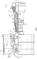
- FIG. 1 schematically illustrates a gas turbine engine 20.
- the gas turbine engine 20 is disclosed herein as a two-spool turbofan that generally incorporates a fan section 22, a compressor section 24, a combustor section 26 and a turbine section 28.
- Alternative engines might include other systems or features.
- the fan section 22 drives air along a bypass flow path B in a bypass duct, while the compressor section 24 drives air along a core flow path C for compression and communication into the combustor section 26 and then expansion through the turbine section 28.
- the exemplary gas turbine engine 20 generally includes a low speed spool 30 and a high speed spool 32 mounted for rotation about an engine central longitudinal axis A relative to an engine static structure 36 via several bearing systems 38. It should be understood that various bearing systems 38 at various locations may alternatively or additionally be provided, and the location of bearing systems 38 may be varied as appropriate to the application.
- the low speed spool 30 generally includes an inner shaft 40 that interconnects a fan 42, a low pressure compressor 44 and a low pressure turbine 46.
- the inner shaft 40 is connected to the fan 42 through a speed change mechanism, which in exemplary gas turbine engine 20 is illustrated as a geared architecture 48 to drive the fan 42 at a lower speed than the low speed spool 30.
- the high speed spool 32 includes an outer shaft 50 that interconnects a high pressure compressor 52 and high pressure turbine 54.
- a combustor 56 is arranged in the gas turbine engine 20 between the high pressure compressor 52 and the high pressure turbine 54.
- the engine static structure 36 is arranged generally between the high pressure turbine 54 and the low pressure turbine 46.
- the engine static structure 36 further supports the bearing systems 38 in the turbine section 28.
- the inner shaft 40 and the outer shaft 50 are concentric and rotate via bearing systems 38 about the engine central longitudinal axis A which is collinear with their longitudinal axes.
- the core airflow is compressed by the low pressure compressor 44 and then the high pressure compressor 52, is mixed and burned with fuel in the combustor 56 and is then expanded over the high pressure turbine 54 and the low pressure turbine 46.
- the high and low pressure turbines 54 and 46 rotationally drive the low speed spool 30 and the high speed spool 32, respectively, in response to the expansion.
- geared architecture 48 may be located aft of the combustor section 26 or even aft of the turbine section 28, and the fan section 22 may be positioned forward or aft of the location of geared architecture 48.
- the compressor section 24 includes a casing or, more particularly, a split casing that is formed by casting.
- compressor split case castings can have geometries that can be difficult to cast while remaining within required tolerances and while achieving required quality.
- shell creation processes can be made more difficult by tight bends or areas that tend to trap shell slurry. This can lead to locally thickened areas in shell layers that do not cure to required quality.
- metal is later poured into a mold in liquid form, the liquid metal has to flow around the same tight bends.
- the material of the shell layers in those tight bends is not as strong as it needs to be due to lack of proper curing or other similar issues, the material of the shell layers will tend to be more prone to failure and thus pieces of the shell layers can break off and become depositing throughout the liquid metal. In certain extreme cases, this can result in liquid metal flowing out of the mold and into an unintended location.
- a split casing for a compressor of a gas turbine engine such as the gas turbine engine 20 of FIG. 1 .
- the split casing has relatively high-radius bends and a filled-in pocket that was otherwise prone to catching shell slurry.
- the fill-in pocket no longer catches shell slurry, which is more able to create an even coating.
- a flow of the shell slurry over the corresponding wax pattern is improved and again provides for the creation of a more even coating which is then stronger during the pouring of liquid metal for casting.
- the liquid metal will not be flowing around as tight of a bend during the casting process, local shell layers will tend to experience reduced stress.
- a compressor casing 201 is provided for use in the compressor section 24 of the gas turbine engine 20 of FIG. 1 .
- the compressor casing 201 includes a circumferential outer wall 210, which is formed to define a circumferential array 211 of openings 212 for receiving additional parts, a circumferential rail 220 extending radially inwardly from the outer wall 210 and including scallop features 230 and smooth and continuous transitions 235 between neighboring scallop features 230 and a circumferential inner wall 240.
- the outer wall 210 includes bosses 213 at each of the openings 212 that protrude radially outwardly from an outer surface 214 of the outer wall 210.
- Each of the scallop features 230 is formed to encompass a single pathway 231 and an opening 212 and each single pathway 231 corresponds to a single scallop feature 230.
- the inner wall 240 is connected with a radially inboard end 221 of the rail 220.
- the inner wall 240 includes a first platform surface 241 and a second platform surface 242.
- the first platform surface 241 is provided at a first side 301 (see FIG. 3 ) of the rail 220 and includes first fillets 401 (see FIG. 4 ) respectively interfacing with first sides 411 of the scallop features 230.
- the second platform surface 242 is disposed radially outboard of the first platform surface 241 (see FIG. 4 ) at a second side 302 (see FIG. 3 ) of the rail 220 opposite the first side 301 and includes second fillets 402 (see FIG. 4 ) respectively interfacing with second sides 412 of the scallop features 230.
- FIGS. 2 , 3 and 4 and the accompanying text refer to both the rail 220 including smooth and continuous transitions 235 between neighboring scallop features 230 and to the second platform surface 242 being disposed radially outboard of the first platform surface 241, this is done for purposes of clarity and brevity and should not be interpreted in any way to otherwise limit the scope of this description or the following claims. Moreover, it is to be further understood that it is not necessary that these features be provided together and that embodiments exist in which the features are separate from one another.
- the rail 220 can include the smooth and continuous transitions 235 between neighboring scallop features 230 without the second platform surface 242 being disposed radially outboard of the first platform surface 241.
- the rail 220 may not include the smooth and continuous transitions 235 between neighboring scallop features 230 whereas the second platform surface 242 is disposed radially outboard of the first platform surface 241.
- the following description will continue to relate to both features as provided above.
- the smooth and continuous transitions 235 between neighboring scallop features 230 are characterized as having a smooth and repeating curvature around each of the scallop features 230 and between each of the neighboring scallop features 230.
- the rail 220 can be configured with an absence of a sharp edge between neighboring scallop features 230.
- the smooth and continuous transitions 235 and the absence of the sharp edge between neighboring scallop features 230 allows for a smooth flow of slurry during casting avoids the potential for weak slurry layers and/or later breakage of cured slurry into molten metallic material. This improves the castability of the compressor casing 201.
- radially outboard-most portions of the second fillets 402 extend radially outwardly beyond an outward radial extent of radially outboard-most portions of the first fillets 401.
- a circumferential plane CP1 of the the second platform surface 242 is radially outboard of a corresponding circumferential plane CP2 of the first platform surface 241 with the second platform surface 242 being a radially outermost surface of the inner wall 240 aft of aft-most portions of the second fillets 402.
- the inner wall 240 can be characterized as lacking a pocket or an aft edge rail that would otherwise tend to inhibit the flow of slurry or cause undesirable pooling of the slurry. This improves the castability of the compressor casing at the cost of some additional weight (i.e., around 1 lb total), which is effectively negligible especially in view of the improved castability.
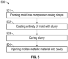
- a casting method 500 includes forming a mold, such as a lost wax mold, into a compressor casing shape as generally described above (block 501), coating an entirety of the mold with slurry (block 502), curing the slurry to form a cavity (block 503) and injecting molten metallic material into the cavity (block 504).
- a mold such as a lost wax mold
- Benefits of the features described herein are the provision of a split casing of a compressor that exhibits improved castabality and reduced defects. While prior case designs often prioritized weight reductions over castability, the split casing described herein incorporates changes for the benefit of castability and producibility at a minimal cost of only slightly increased weight.
Landscapes
- Engineering & Computer Science (AREA)
- Mechanical Engineering (AREA)
- General Engineering & Computer Science (AREA)
- Structures Of Non-Positive Displacement Pumps (AREA)
Abstract
A compressor casing is provided. The compressor casing includes an outer wall (210), a rail (220) extending inwardly from the outer wall (210) and comprising scallop features (230) encompassing pathways and an inner wall (240) connected with an inboard end (221) of the rail (220). The inner wall (240) includes a first platform surface (241) at a first side (301) of the rail (220) and including first fillets (401) interfacing with first sides (411) of the scallop features (230) and a second platform surface (242) outboard of the first platform surface (241) at a second side (302) of the rail (220) opposite the first side (301) and including second fillets (402) interfacing with second sides (412) of the scallop features (230).
Description
- Exemplary embodiments of the present disclosure relate generally to gas turbine engines and, in one embodiment, to a gas turbine engine that includes a split case having a castable pocket.
- In a gas turbine engine, air is compressed in a compressor and compressor air is then mixed with fuel and combusted in a combustor to produce a high-temperture and high-pressure working fluid. This working fluid is directed into a turbine in which the working fluid is expanded to generate power. The generated power drives the rotation of a rotor within the turbine through aerodynamic interactions between the working fluid and turbine blades or airfoils. The rotor can be used to drive rotations of a propeller or fan or to produce electricity in a generator.
- In many gas turbine engines, the compressor and the turbine include casings that are often cast. However, since casings of gas turbine engines typically have complex geometries, executing the casting processes can be difficult.
- Accordingly, a need exists for a casing of a gas turbine engine that can be easily cast.
- According to an aspect of the present invention, a compressor casing is provided. The compressor casing includes an outer wall, a rail extending inwardly from the outer wall and including scallop features encompassing pathways and an inner wall connected with an inboard end of the rail. The inner wall includes a first platform surface at a first side of the rail and including first fillets interfacing with first sides of the scallop features and a second platform surface outboard of the first platform surface at a second side of the rail opposite the first side and including second fillets interfacing with second sides of the scallop features.
- In an embodiment of the above, the outer and inner walls and the rail are circumferential features.
- In an embodiment according to any of the previous embodiments, bosses that protrude radially outwardly from an outer surface of the outer wall.
- In an embodiment according to any of the previous embodiments, each scallop feature encompasses a single pathway.
- In an embodiment according to any of the previous embodiments, the rail includes smooth and continuous transitions between neighboring scallop features.
- In an embodiment according to any of the previous embodiments, the rail is configured with an absence of a sharp edge between neighboring scallop features.
- In an embodiment according to any of the previous embodiments, the second fillets extend radially outwardly beyond an outward radial extent of the first fillets.
- In an embodiment according to any of the previous embodiments, a circumferential plane of the the second platform surface is outboard of a corresponding circumferential plane of the first platform surface.
- In an embodiment according to any of the previous embodiments, the second platform surface is a radially outermost surface of the inner wall aft of the second fillets.
- According to another aspect of the present invention, a compressor casing is provided. The compressor casing includes an outer wall, a rail extending inwardly from the outer wall and including scallop features encompassing pathways with smooth and continuous transitions between neighboring scallop features and an inner wall connected with an inboard end of the rail and including platform surfaces with fillets interfacing with the scallop features.
- In an embodiment of the above, the outer and inner walls and the rail are circumferential features.
- In an embodiment according to any of the previous embodiments, bosses that protrude radially outwardly from an outer surface of the outer wall.
- In an embodiment according to any of the previous embodiments, each scallop feature encompasses a single pathway.
- In an embodiment according to any of the previous embodiments, the rail is configured with an absence of a sharp edge between the neighboring scallop features.
- In an embodiment according to any of the previous embodiments, the inner wall includes a first platform surface at a first side of the rail and includes first fillets interfacing with first sides of the scallop features and a second platform surface at a second side of the rail opposite the first side and including second fillets interfacing with second sides of the scallop features.
- In an embodiment according to any of the previous embodiments, the second fillets extend radially outwardly beyond an outward radial extent of the first fillets.
- In an embodiment according to any of the previous embodiments, a circumferential plane of the the second platform surface is outboard of a corresponding circumferential plane of the first platform surface.
- In an embodiment according to any of the previous embodiments, the second platform surface is a radially outermost surface of the inner wall aft of the second fillets.
- According to another aspect of the present invention, a casting method is provided and includes forming a mold into a compressor casing shape. The compressor casing shape includes an outer wall, a rail extending inwardly from the outer wall and including scallop features encompassing pathways with smooth and continuous transitions between neighboring scallop features and an inner wall connected with an inboard end of the rail. The inner wall includes a first platform surface at a first side of the rail and including first fillets interfacing with first sides of the scallop features and a second platform surface outboard of the first platform surface at a second side of the rail opposite the first side and including second fillets interfacing with second sides of the scallop features. The method further includes coating an entirety of the mold with slurry, curing the slurry to form a cavity and injecting molten metallic material into the cavity.
- In an embodiment of the above, the mold is a lost wax mold.
- These and other advantages and features will become more apparent from the following description taken in conjunction with the drawings.
- The following descriptions should not be considered limiting in any way. With reference to the accompanying drawings, like elements are numbered alike:
-
FIG. 1 is a partial cross-sectional view of a gas turbine engine; -
FIG. 2 is a perspective view of a portion of a compressor casing in accordance with embodiments; -
FIG. 3 is a radially inward view of a portion of a compressor casing in accordance with embodiments; and -
FIG. 4 is a side view of a portion of a compressor casing in accordance with embodiments; and -
FIG. 5 is a flow diagram illustrating a casting method in accordance with embodiments. - These and other advantages and features will become more apparent from the following description taken in conjunction with the drawings.
- A detailed description of one or more embodiments of the disclosed apparatus and method are presented herein by way of exemplification and not limitation with reference to the Figures.
-
FIG. 1 schematically illustrates agas turbine engine 20. Thegas turbine engine 20 is disclosed herein as a two-spool turbofan that generally incorporates afan section 22, acompressor section 24, acombustor section 26 and aturbine section 28. Alternative engines might include other systems or features. Thefan section 22 drives air along a bypass flow path B in a bypass duct, while thecompressor section 24 drives air along a core flow path C for compression and communication into thecombustor section 26 and then expansion through theturbine section 28. Although depicted as a two-spool turbofan gas turbine engine in the disclosed non-limiting embodiment, it should be understood that the concepts described herein are not limited to use with two-spool turbofans as the teachings may be applied to other types of turbine engines including three-spool architectures. - The exemplary
gas turbine engine 20 generally includes alow speed spool 30 and ahigh speed spool 32 mounted for rotation about an engine central longitudinal axis A relative to an enginestatic structure 36 viaseveral bearing systems 38. It should be understood thatvarious bearing systems 38 at various locations may alternatively or additionally be provided, and the location ofbearing systems 38 may be varied as appropriate to the application. - The
low speed spool 30 generally includes aninner shaft 40 that interconnects afan 42, alow pressure compressor 44 and alow pressure turbine 46. Theinner shaft 40 is connected to thefan 42 through a speed change mechanism, which in exemplarygas turbine engine 20 is illustrated as a gearedarchitecture 48 to drive thefan 42 at a lower speed than thelow speed spool 30. Thehigh speed spool 32 includes anouter shaft 50 that interconnects ahigh pressure compressor 52 andhigh pressure turbine 54. Acombustor 56 is arranged in thegas turbine engine 20 between thehigh pressure compressor 52 and thehigh pressure turbine 54. The enginestatic structure 36 is arranged generally between thehigh pressure turbine 54 and thelow pressure turbine 46. The enginestatic structure 36 further supports thebearing systems 38 in theturbine section 28. Theinner shaft 40 and theouter shaft 50 are concentric and rotate viabearing systems 38 about the engine central longitudinal axis A which is collinear with their longitudinal axes. - The core airflow is compressed by the
low pressure compressor 44 and then thehigh pressure compressor 52, is mixed and burned with fuel in thecombustor 56 and is then expanded over thehigh pressure turbine 54 and thelow pressure turbine 46. The high andlow pressure turbines low speed spool 30 and thehigh speed spool 32, respectively, in response to the expansion. It will be appreciated that each of the positions of thefan section 22,compressor section 24,combustor section 26,turbine section 28, and fandrive gear system 48 may be varied. For example, gearedarchitecture 48 may be located aft of thecombustor section 26 or even aft of theturbine section 28, and thefan section 22 may be positioned forward or aft of the location of gearedarchitecture 48. - With continued reference to
FIG. 1 , thecompressor section 24 includes a casing or, more particularly, a split casing that is formed by casting. Currently, however, compressor split case castings can have geometries that can be difficult to cast while remaining within required tolerances and while achieving required quality. With a lost wax casting method, for instance, shell creation processes can be made more difficult by tight bends or areas that tend to trap shell slurry. This can lead to locally thickened areas in shell layers that do not cure to required quality. In these or other cases, when metal is later poured into a mold in liquid form, the liquid metal has to flow around the same tight bends. If the material of the shell layers in those tight bends is not as strong as it needs to be due to lack of proper curing or other similar issues, the material of the shell layers will tend to be more prone to failure and thus pieces of the shell layers can break off and become depositing throughout the liquid metal. In certain extreme cases, this can result in liquid metal flowing out of the mold and into an unintended location. - Accordingly, a need exists for a casing of a gas turbine engine that can be easily cast as compared to conventional split casings.
- Therefore, as will be described below, a split casing for a compressor of a gas turbine engine, such as the
gas turbine engine 20 ofFIG. 1 , is provided. The split casing has relatively high-radius bends and a filled-in pocket that was otherwise prone to catching shell slurry. The fill-in pocket no longer catches shell slurry, which is more able to create an even coating. Additionally, by increasing the radii of the bends, a flow of the shell slurry over the corresponding wax pattern is improved and again provides for the creation of a more even coating which is then stronger during the pouring of liquid metal for casting. In addition, since the liquid metal will not be flowing around as tight of a bend during the casting process, local shell layers will tend to experience reduced stress. - With reference to
FIGS. 2 ,3 and 4 , acompressor casing 201 is provided for use in thecompressor section 24 of thegas turbine engine 20 ofFIG. 1 . Thecompressor casing 201 includes a circumferentialouter wall 210, which is formed to define acircumferential array 211 ofopenings 212 for receiving additional parts, acircumferential rail 220 extending radially inwardly from theouter wall 210 and including scallop features 230 and smooth andcontinuous transitions 235 between neighboring scallop features 230 and a circumferentialinner wall 240. Theouter wall 210 includesbosses 213 at each of theopenings 212 that protrude radially outwardly from anouter surface 214 of theouter wall 210. Each of the scallop features 230 is formed to encompass asingle pathway 231 and anopening 212 and eachsingle pathway 231 corresponds to asingle scallop feature 230. Theinner wall 240 is connected with a radiallyinboard end 221 of therail 220. Theinner wall 240 includes afirst platform surface 241 and asecond platform surface 242. Thefirst platform surface 241 is provided at a first side 301 (seeFIG. 3 ) of therail 220 and includes first fillets 401 (seeFIG. 4 ) respectively interfacing withfirst sides 411 of the scallop features 230. Thesecond platform surface 242 is disposed radially outboard of the first platform surface 241 (seeFIG. 4 ) at a second side 302 (seeFIG. 3 ) of therail 220 opposite thefirst side 301 and includes second fillets 402 (seeFIG. 4 ) respectively interfacing withsecond sides 412 of the scallop features 230. - It is to be understood that while
FIGS. 2 ,3 and 4 and the accompanying text refer to both therail 220 including smooth andcontinuous transitions 235 between neighboring scallop features 230 and to thesecond platform surface 242 being disposed radially outboard of thefirst platform surface 241, this is done for purposes of clarity and brevity and should not be interpreted in any way to otherwise limit the scope of this description or the following claims. Moreover, it is to be further understood that it is not necessary that these features be provided together and that embodiments exist in which the features are separate from one another. For example, in some cases, therail 220 can include the smooth andcontinuous transitions 235 between neighboring scallop features 230 without thesecond platform surface 242 being disposed radially outboard of thefirst platform surface 241. As another example, in some cases, therail 220 may not include the smooth andcontinuous transitions 235 between neighboring scallop features 230 whereas thesecond platform surface 242 is disposed radially outboard of thefirst platform surface 241. The following description will continue to relate to both features as provided above. - With continued reference to
FIGS. 2 and3 , the smooth andcontinuous transitions 235 between neighboring scallop features 230 are characterized as having a smooth and repeating curvature around each of the scallop features 230 and between each of the neighboring scallop features 230. As such, it is apparent that therail 220 can be configured with an absence of a sharp edge between neighboring scallop features 230. The smooth andcontinuous transitions 235 and the absence of the sharp edge between neighboring scallop features 230 allows for a smooth flow of slurry during casting avoids the potential for weak slurry layers and/or later breakage of cured slurry into molten metallic material. This improves the castability of thecompressor casing 201. - With continued reference to
FIGS. 2 and4 , radially outboard-most portions of thesecond fillets 402 extend radially outwardly beyond an outward radial extent of radially outboard-most portions of thefirst fillets 401. In addition, a circumferential plane CP1 of the thesecond platform surface 242 is radially outboard of a corresponding circumferential plane CP2 of thefirst platform surface 241 with thesecond platform surface 242 being a radially outermost surface of theinner wall 240 aft of aft-most portions of thesecond fillets 402. As such, theinner wall 240 can be characterized as lacking a pocket or an aft edge rail that would otherwise tend to inhibit the flow of slurry or cause undesirable pooling of the slurry. This improves the castability of the compressor casing at the cost of some additional weight (i.e., around 1 lb total), which is effectively negligible especially in view of the improved castability. - With reference to
FIG. 5 , acasting method 500 is provided and includes forming a mold, such as a lost wax mold, into a compressor casing shape as generally described above (block 501), coating an entirety of the mold with slurry (block 502), curing the slurry to form a cavity (block 503) and injecting molten metallic material into the cavity (block 504). - Benefits of the features described herein are the provision of a split casing of a compressor that exhibits improved castabality and reduced defects. While prior case designs often prioritized weight reductions over castability, the split casing described herein incorporates changes for the benefit of castability and producibility at a minimal cost of only slightly increased weight.
- The term "about" is intended to include the degree of error associated with measurement of the particular quantity based upon the equipment available at the time of filing the application.
- The terminology used herein is for the purpose of describing particular embodiments only and is not intended to be limiting of the present disclosure. As used herein, the singular forms "a", "an" and "the" are intended to include the plural forms as well, unless the context clearly indicates otherwise. It will be further understood that the terms "comprises" and/or "comprising," when used in this specification, specify the presence of stated features, integers, steps, operations, elements, and/or components, but do not preclude the presence or addition of one or more other features, integers, steps, operations, element components, and/or groups thereof.
- While the present disclosure has been described with reference to an exemplary embodiment or embodiments, it will be understood by those skilled in the art that various changes may be made and equivalents may be substituted for elements thereof without departing from the scope of the present disclosure. In addition, many modifications may be made to adapt a particular situation or material to the teachings of the present disclosure without departing from the essential scope thereof. Therefore, it is intended that the present disclosure not be limited to the particular embodiment disclosed as the best mode contemplated for carrying out this present disclosure, but that the present disclosure will include all embodiments falling within the scope of the claims.
Claims (13)
- A compressor casing, comprising:an outer wall (210);a rail (220) extending inwardly from the outer wall (210) and comprising scallop features (230) encompassing pathways; andan inner wall (240) connected with an inboard end (221) of the rail (220) and comprising:a first platform surface (241) at a first side (301) of the rail (220) and comprising first fillets (401) interfacing with first sides (411) of the scallop features (230); anda second platform surface (242) outboard of the first platform surface (241) at a second side (302) of the rail (220) opposite the first side (301) and comprising second fillets (402) interfacing with second sides (412) of the scallop features (230).
- The compressor casing according to claim 1, wherein the rail (220) comprises smooth and continuous transitions (235) between neighboring scallop features (230).
- A compressor casing, comprising:an outer wall (210);a rail (220) extending inwardly from the outer wall (210) and comprising scallop features (230) encompassing pathways with smooth and continuous transitions (235) between neighboring scallop features (230); andan inner wall (240) connected with an inboard end (221) of the rail (220) and comprising platform surfaces with fillets interfacing with the scallop features (230).
- The compressor casing according to claim 3, wherein the inner wall (240) comprises:a first platform surface (241) at a first side (301) of the rail (220) and comprising first fillets (401) interfacing with first sides (411) of the scallop features (230); anda second platform surface (242) at a second side (302) of the rail (220) opposite the first side (301) and comprising second fillets (402) interfacing with second sides (412) of the scallop features (230).
- The compressor casing according to claim 1, 2 or 4, wherein the second fillets (402) extend radially outwardly beyond an outward radial extent of the first fillets (401).
- The compressor casing according to claim 1, 2, 4 or 5, wherein a circumferential plane (CP1) of the the second platform surface (242) is outboard of a corresponding circumferential plane (CP2) of the first platform surface (241).
- The compressor casing according to any of claims 1, 2, 4, 5 or 6, wherein the second platform surface (242) is a radially outermost surface of the inner wall (240) aft of the second fillets (402).
- The compressor casing according to any preceding claim, wherein the outer and inner walls (210, 240) and the rail (220) are circumferential features.
- The compressor casing according to any preceding claim, further comprising bosses (213) that protrude radially outwardly from an outer surface (214) of the outer wall (210).
- The compressor casing according to any preceding claim, wherein each scallop feature (230) encompasses a single pathway (231).
- The compressor casing according to any preceding claim, wherein the rail (220) is configured with an absence of a sharp edge between the neighboring scallop features (230).
- A casting method, comprising:forming a mold into a compressor casing shape comprising:an outer wall (210);a rail (220) extending inwardly from the outer wall (210) and comprising scallop features (230) encompassing pathways with smooth and continuous transitions (235) between neighboring scallop features (230); andan inner wall (240) connected with an inboard end (221) of the rail (220) and comprising:a first platform surface (241) at a first side (301) of the rail (220) and comprising first fillets (401) interfacing with first sides (411) of the scallop features (230); anda second platform surface (242) outboard of the first platform surface (241) at a second side (302) of the rail (220) opposite the first side (301) and comprising second fillets (402) interfacing with second sides (412) of the scallop features (230),the method further comprising coating an entirety of the mold with slurry, curing the slurry to form a cavity and injecting molten metallic material into the cavity.
- The casting method according to claim 12, wherein the mold is a lost wax mold.
Applications Claiming Priority (1)
| Application Number | Priority Date | Filing Date | Title |
|---|---|---|---|
| US18/540,507 US12281588B1 (en) | 2023-12-14 | 2023-12-14 | Split case having castable pocket |
Publications (1)
| Publication Number | Publication Date |
|---|---|
| EP4575192A1 true EP4575192A1 (en) | 2025-06-25 |
Family
ID=93923776
Family Applications (1)
| Application Number | Title | Priority Date | Filing Date |
|---|---|---|---|
| EP24219891.9A Pending EP4575192A1 (en) | 2023-12-14 | 2024-12-13 | Compressor case of a gas turbine engine |
Country Status (2)
| Country | Link |
|---|---|
| US (1) | US12281588B1 (en) |
| EP (1) | EP4575192A1 (en) |
Citations (3)
| Publication number | Priority date | Publication date | Assignee | Title |
|---|---|---|---|---|
| US10495108B2 (en) * | 2017-01-31 | 2019-12-03 | Honeywell International Inc. | Variable vane devices containing rotationally-driven translating vane structures and methods for the production thereof |
| US10711626B2 (en) * | 2014-11-25 | 2020-07-14 | MTU Aero Engines AG | Guide vane ring and turbomachine |
| US10794200B2 (en) * | 2018-09-14 | 2020-10-06 | United Technologies Corporation | Integral half vane, ringcase, and id shroud |
Family Cites Families (14)
| Publication number | Priority date | Publication date | Assignee | Title |
|---|---|---|---|---|
| US6702550B2 (en) * | 2002-01-16 | 2004-03-09 | General Electric Company | Turbine shroud segment and shroud assembly |
| US6984106B2 (en) * | 2004-01-08 | 2006-01-10 | General Electric Company | Resilent seal on leading edge of turbine inner shroud |
| US7338253B2 (en) * | 2005-09-15 | 2008-03-04 | General Electric Company | Resilient seal on trailing edge of turbine inner shroud and method for shroud post impingement cavity sealing |
| US8784037B2 (en) * | 2011-08-31 | 2014-07-22 | Pratt & Whitney Canada Corp. | Turbine shroud segment with integrated impingement plate |
| FR2983924B1 (en) | 2011-12-09 | 2013-11-22 | Snecma | ANNULAR HOUSING FOR A TURBOMACHINE COMPRESSOR |
| US10012385B2 (en) * | 2014-08-08 | 2018-07-03 | Pratt & Whitney Canada Corp. | Combustor heat shield sealing |
| EP3040617B1 (en) * | 2014-12-31 | 2017-12-06 | Rolls-Royce North American Technologies, Inc. | Retention system for gas turbine engine assemblies |
| FR3033825B1 (en) * | 2015-03-16 | 2018-09-07 | Safran Aircraft Engines | TURBINE RING ASSEMBLY OF CERAMIC MATRIX COMPOSITE MATERIAL |
| FR3048016B1 (en) * | 2016-02-18 | 2018-03-16 | Safran Ceramics | TURBINE RING SECTOR WITH ENVIRONMENTAL BARRIER DOPED BY AN ELECTRICALLY CONDUCTIVE ELEMENT |
| US10082039B2 (en) * | 2016-11-02 | 2018-09-25 | United Technologies Corporation | Segmented annular seal |
| US10677084B2 (en) * | 2017-06-16 | 2020-06-09 | Honeywell International Inc. | Turbine tip shroud assembly with plural shroud segments having inter-segment seal arrangement |
| FR3072720B1 (en) * | 2017-10-23 | 2019-09-27 | Safran Aircraft Engines | CARTRIDGE FOR TURBOMACHINE COMPRISING A CENTRAL PORTION PROJECTED IN RELATION TO TWO SIDE PORTIONS IN A JUNCTION REGION |
| US11220924B2 (en) * | 2019-09-26 | 2022-01-11 | Raytheon Technologies Corporation | Double box composite seal assembly with insert for gas turbine engine |
| US11725525B2 (en) | 2022-01-19 | 2023-08-15 | Rolls-Royce North American Technologies Inc. | Engine section stator vane assembly with band stiffness features for turbine engines |
-
2023
- 2023-12-14 US US18/540,507 patent/US12281588B1/en active Active
-
2024
- 2024-12-13 EP EP24219891.9A patent/EP4575192A1/en active Pending
Patent Citations (3)
| Publication number | Priority date | Publication date | Assignee | Title |
|---|---|---|---|---|
| US10711626B2 (en) * | 2014-11-25 | 2020-07-14 | MTU Aero Engines AG | Guide vane ring and turbomachine |
| US10495108B2 (en) * | 2017-01-31 | 2019-12-03 | Honeywell International Inc. | Variable vane devices containing rotationally-driven translating vane structures and methods for the production thereof |
| US10794200B2 (en) * | 2018-09-14 | 2020-10-06 | United Technologies Corporation | Integral half vane, ringcase, and id shroud |
Also Published As
| Publication number | Publication date |
|---|---|
| US12281588B1 (en) | 2025-04-22 |
Similar Documents
| Publication | Publication Date | Title |
|---|---|---|
| US11014145B2 (en) | Core assembly including studded spacer | |
| EP3170981A1 (en) | Baffle for a component of a gas turbine engine | |
| EP3633150A1 (en) | Multi-walled airfoil core | |
| US20190176228A1 (en) | Gas turbine engine component cooling passage and space eating core | |
| EP3771514A1 (en) | Baffle tube with two datum features | |
| EP3034196B1 (en) | Reinforced ceramic core for component casting | |
| WO2014175940A2 (en) | Gas turbine engine component manufacturing method and core for making same | |
| EP3650655B1 (en) | Airfoil, corresponding gas turbine engine and method for assembling | |
| US10024181B2 (en) | Casting of thin wall hollow airfoil sections | |
| US20210115799A1 (en) | Angled tip rods | |
| EP3108981B1 (en) | Core assembly for gas turbine engine | |
| EP3170983B1 (en) | Platform and corresponding method of manufacturing | |
| EP3219922A1 (en) | Seal arc segment with anti-rotation feature | |
| US12281588B1 (en) | Split case having castable pocket | |
| EP3693547B1 (en) | Gas turbine engine blade, gas turbine engine and method of manufacturing a gas turbine engine blade | |
| EP2969314B1 (en) | Cast component having corner radius to reduce recrystallization | |
| EP3633148B1 (en) | Composite cast porous metal turbine component and corresponding fabricating methods | |
| EP3808473B1 (en) | Casting core assembly comprising a bumper surrounding a metal pin and associated method of manufacture. | |
| EP3663520B1 (en) | Composite fan blade with leading edge sheath | |
| EP4166760B1 (en) | Angled tip rods used to cast holes in tips of blade cores of airfoils | |
| EP3406851A1 (en) | Component for a gas turbine engine and method of forming a core assembly |
Legal Events
| Date | Code | Title | Description |
|---|---|---|---|
| PUAI | Public reference made under article 153(3) epc to a published international application that has entered the european phase |
Free format text: ORIGINAL CODE: 0009012 |
|
| STAA | Information on the status of an ep patent application or granted ep patent |
Free format text: STATUS: THE APPLICATION HAS BEEN PUBLISHED |
|
| AK | Designated contracting states |
Kind code of ref document: A1 Designated state(s): AL AT BE BG CH CY CZ DE DK EE ES FI FR GB GR HR HU IE IS IT LI LT LU LV MC ME MK MT NL NO PL PT RO RS SE SI SK SM TR |
|
| STAA | Information on the status of an ep patent application or granted ep patent |
Free format text: STATUS: REQUEST FOR EXAMINATION WAS MADE |
|
| 17P | Request for examination filed |
Effective date: 20251212 |