EP4575185A1 - Split case of a gas turbine engine with thermal barrier coating - Google Patents
Split case of a gas turbine engine with thermal barrier coating Download PDFInfo
- Publication number
- EP4575185A1 EP4575185A1 EP24219793.7A EP24219793A EP4575185A1 EP 4575185 A1 EP4575185 A1 EP 4575185A1 EP 24219793 A EP24219793 A EP 24219793A EP 4575185 A1 EP4575185 A1 EP 4575185A1
- Authority
- EP
- European Patent Office
- Prior art keywords
- section
- linear portion
- split case
- angle
- linear
- Prior art date
- Legal status (The legal status is an assumption and is not a legal conclusion. Google has not performed a legal analysis and makes no representation as to the accuracy of the status listed.)
- Pending
Links
Images

Classifications
-
- F—MECHANICAL ENGINEERING; LIGHTING; HEATING; WEAPONS; BLASTING
- F01—MACHINES OR ENGINES IN GENERAL; ENGINE PLANTS IN GENERAL; STEAM ENGINES
- F01D—NON-POSITIVE DISPLACEMENT MACHINES OR ENGINES, e.g. STEAM TURBINES
- F01D25/00—Component parts, details, or accessories, not provided for in, or of interest apart from, other groups
- F01D25/08—Cooling; Heating; Heat-insulation
- F01D25/14—Casings modified therefor
- F01D25/145—Thermally insulated casings
-
- F—MECHANICAL ENGINEERING; LIGHTING; HEATING; WEAPONS; BLASTING
- F01—MACHINES OR ENGINES IN GENERAL; ENGINE PLANTS IN GENERAL; STEAM ENGINES
- F01D—NON-POSITIVE DISPLACEMENT MACHINES OR ENGINES, e.g. STEAM TURBINES
- F01D25/00—Component parts, details, or accessories, not provided for in, or of interest apart from, other groups
- F01D25/24—Casings; Casing parts, e.g. diaphragms, casing fastenings
-
- F—MECHANICAL ENGINEERING; LIGHTING; HEATING; WEAPONS; BLASTING
- F01—MACHINES OR ENGINES IN GENERAL; ENGINE PLANTS IN GENERAL; STEAM ENGINES
- F01D—NON-POSITIVE DISPLACEMENT MACHINES OR ENGINES, e.g. STEAM TURBINES
- F01D25/00—Component parts, details, or accessories, not provided for in, or of interest apart from, other groups
- F01D25/24—Casings; Casing parts, e.g. diaphragms, casing fastenings
- F01D25/246—Fastening of diaphragms or stator-rings
-
- F—MECHANICAL ENGINEERING; LIGHTING; HEATING; WEAPONS; BLASTING
- F01—MACHINES OR ENGINES IN GENERAL; ENGINE PLANTS IN GENERAL; STEAM ENGINES
- F01D—NON-POSITIVE DISPLACEMENT MACHINES OR ENGINES, e.g. STEAM TURBINES
- F01D25/00—Component parts, details, or accessories, not provided for in, or of interest apart from, other groups
- F01D25/24—Casings; Casing parts, e.g. diaphragms, casing fastenings
- F01D25/26—Double casings; Measures against temperature strain in casings
-
- F—MECHANICAL ENGINEERING; LIGHTING; HEATING; WEAPONS; BLASTING
- F01—MACHINES OR ENGINES IN GENERAL; ENGINE PLANTS IN GENERAL; STEAM ENGINES
- F01D—NON-POSITIVE DISPLACEMENT MACHINES OR ENGINES, e.g. STEAM TURBINES
- F01D25/00—Component parts, details, or accessories, not provided for in, or of interest apart from, other groups
- F01D25/24—Casings; Casing parts, e.g. diaphragms, casing fastenings
- F01D25/26—Double casings; Measures against temperature strain in casings
- F01D25/265—Vertically split casings; Clamping arrangements therefor
-
- F—MECHANICAL ENGINEERING; LIGHTING; HEATING; WEAPONS; BLASTING
- F01—MACHINES OR ENGINES IN GENERAL; ENGINE PLANTS IN GENERAL; STEAM ENGINES
- F01D—NON-POSITIVE DISPLACEMENT MACHINES OR ENGINES, e.g. STEAM TURBINES
- F01D5/00—Blades; Blade-carrying members; Heating, heat-insulating, cooling or antivibration means on the blades or the members
- F01D5/12—Blades
- F01D5/28—Selecting particular materials; Particular measures relating thereto; Measures against erosion or corrosion
-
- F—MECHANICAL ENGINEERING; LIGHTING; HEATING; WEAPONS; BLASTING
- F01—MACHINES OR ENGINES IN GENERAL; ENGINE PLANTS IN GENERAL; STEAM ENGINES
- F01D—NON-POSITIVE DISPLACEMENT MACHINES OR ENGINES, e.g. STEAM TURBINES
- F01D9/00—Stators
- F01D9/02—Nozzles; Nozzle boxes; Stator blades; Guide conduits, e.g. individual nozzles
- F01D9/023—Transition ducts between combustor cans and first stage of the turbine in gas-turbine engines; their cooling or sealings
-
- F—MECHANICAL ENGINEERING; LIGHTING; HEATING; WEAPONS; BLASTING
- F05—INDEXING SCHEMES RELATING TO ENGINES OR PUMPS IN VARIOUS SUBCLASSES OF CLASSES F01-F04
- F05D—INDEXING SCHEME FOR ASPECTS RELATING TO NON-POSITIVE-DISPLACEMENT MACHINES OR ENGINES, GAS-TURBINES OR JET-PROPULSION PLANTS
- F05D2220/00—Application
- F05D2220/30—Application in turbines
- F05D2220/32—Application in turbines in gas turbines
-
- F—MECHANICAL ENGINEERING; LIGHTING; HEATING; WEAPONS; BLASTING
- F05—INDEXING SCHEMES RELATING TO ENGINES OR PUMPS IN VARIOUS SUBCLASSES OF CLASSES F01-F04
- F05D—INDEXING SCHEME FOR ASPECTS RELATING TO NON-POSITIVE-DISPLACEMENT MACHINES OR ENGINES, GAS-TURBINES OR JET-PROPULSION PLANTS
- F05D2220/00—Application
- F05D2220/30—Application in turbines
- F05D2220/32—Application in turbines in gas turbines
- F05D2220/323—Application in turbines in gas turbines for aircraft propulsion, e.g. jet engines
-
- F—MECHANICAL ENGINEERING; LIGHTING; HEATING; WEAPONS; BLASTING
- F05—INDEXING SCHEMES RELATING TO ENGINES OR PUMPS IN VARIOUS SUBCLASSES OF CLASSES F01-F04
- F05D—INDEXING SCHEME FOR ASPECTS RELATING TO NON-POSITIVE-DISPLACEMENT MACHINES OR ENGINES, GAS-TURBINES OR JET-PROPULSION PLANTS
- F05D2230/00—Manufacture
- F05D2230/10—Manufacture by removing material
-
- F—MECHANICAL ENGINEERING; LIGHTING; HEATING; WEAPONS; BLASTING
- F05—INDEXING SCHEMES RELATING TO ENGINES OR PUMPS IN VARIOUS SUBCLASSES OF CLASSES F01-F04
- F05D—INDEXING SCHEME FOR ASPECTS RELATING TO NON-POSITIVE-DISPLACEMENT MACHINES OR ENGINES, GAS-TURBINES OR JET-PROPULSION PLANTS
- F05D2230/00—Manufacture
- F05D2230/20—Manufacture essentially without removing material
- F05D2230/21—Manufacture essentially without removing material by casting
-
- F—MECHANICAL ENGINEERING; LIGHTING; HEATING; WEAPONS; BLASTING
- F05—INDEXING SCHEMES RELATING TO ENGINES OR PUMPS IN VARIOUS SUBCLASSES OF CLASSES F01-F04
- F05D—INDEXING SCHEME FOR ASPECTS RELATING TO NON-POSITIVE-DISPLACEMENT MACHINES OR ENGINES, GAS-TURBINES OR JET-PROPULSION PLANTS
- F05D2230/00—Manufacture
- F05D2230/90—Coating; Surface treatment
-
- F—MECHANICAL ENGINEERING; LIGHTING; HEATING; WEAPONS; BLASTING
- F05—INDEXING SCHEMES RELATING TO ENGINES OR PUMPS IN VARIOUS SUBCLASSES OF CLASSES F01-F04
- F05D—INDEXING SCHEME FOR ASPECTS RELATING TO NON-POSITIVE-DISPLACEMENT MACHINES OR ENGINES, GAS-TURBINES OR JET-PROPULSION PLANTS
- F05D2240/00—Components
- F05D2240/10—Stators
- F05D2240/11—Shroud seal segments
-
- F—MECHANICAL ENGINEERING; LIGHTING; HEATING; WEAPONS; BLASTING
- F05—INDEXING SCHEMES RELATING TO ENGINES OR PUMPS IN VARIOUS SUBCLASSES OF CLASSES F01-F04
- F05D—INDEXING SCHEME FOR ASPECTS RELATING TO NON-POSITIVE-DISPLACEMENT MACHINES OR ENGINES, GAS-TURBINES OR JET-PROPULSION PLANTS
- F05D2240/00—Components
- F05D2240/10—Stators
- F05D2240/14—Casings or housings protecting or supporting assemblies within
-
- F—MECHANICAL ENGINEERING; LIGHTING; HEATING; WEAPONS; BLASTING
- F05—INDEXING SCHEMES RELATING TO ENGINES OR PUMPS IN VARIOUS SUBCLASSES OF CLASSES F01-F04
- F05D—INDEXING SCHEME FOR ASPECTS RELATING TO NON-POSITIVE-DISPLACEMENT MACHINES OR ENGINES, GAS-TURBINES OR JET-PROPULSION PLANTS
- F05D2240/00—Components
- F05D2240/35—Combustors or associated equipment
-
- F—MECHANICAL ENGINEERING; LIGHTING; HEATING; WEAPONS; BLASTING
- F05—INDEXING SCHEMES RELATING TO ENGINES OR PUMPS IN VARIOUS SUBCLASSES OF CLASSES F01-F04
- F05D—INDEXING SCHEME FOR ASPECTS RELATING TO NON-POSITIVE-DISPLACEMENT MACHINES OR ENGINES, GAS-TURBINES OR JET-PROPULSION PLANTS
- F05D2260/00—Function
- F05D2260/20—Heat transfer, e.g. cooling
- F05D2260/231—Preventing heat transfer
Definitions
- the first linear portion is oriented substantially along a radial dimension.
- the interior surface of the first section has a curvilinear portion which extends from the first linear portion.
- the hook includes a radial section and an axial section extending away from the first angle from an inboard end of the radial section.
- a split case includes a first section including an interior surface with a first linear portion, a second section including a hook, a third section interposed between the first and second sections and including an interior surface with a second linear portion intersecting and forming a simple angle with the first linear portion at an intersection point of the first and second linear portions.
- the simple angle has a magnitude of about 120°.
- the first linear portion is oriented substantially along a radial dimension.
- the hook includes a radial section and an axial section extending away from the simple angle from an inboard end of the radial section.
- a distance between an interior corner of the hook and the second linear portion exceeds a thickness of the axial section.
- the split case further includes first and second thermal barrier coating (TBC) portions applied to at least the first and second linear portions, respectively.
- TBC thermal barrier coating
- the machining includes positioning a machining tool in position to machine the third section, moving the machining tool in a linear pathway along the third section to form the second linear portion and maintaining an orientation of the machining tool during an entirety of the machining.
- the split case formation method further includes applying first and second thermal barrier coating (TBC) portions to at least the first and second linear portions, respectively.
- TBC thermal barrier coating
- FIG. 1 schematically illustrates a gas turbine engine 20.
- the gas turbine engine 20 is disclosed herein as a two-spool turbofan that generally incorporates a fan section 22, a compressor section 24, a combustor section 26 and a turbine section 28.
- Alternative engines might include other systems or features.
- the fan section 22 drives air along a bypass flow path B in a bypass duct, while the compressor section 24 drives air along a core flow path C for compression and communication into the combustor section 26 and then expansion through the turbine section 28.
- the exemplary gas turbine engine 20 generally includes a low speed spool 30 and a high speed spool 32 mounted for rotation about an engine central longitudinal axis A relative to an engine static structure 36 via several bearing systems 38. It should be understood that various bearing systems 38 at various locations may alternatively or additionally be provided, and the location of bearing systems 38 may be varied as appropriate to the application.
- the low speed spool 30 generally includes an inner shaft 40 that interconnects a fan 42, a low pressure compressor 44 and a low pressure turbine 46.
- the inner shaft 40 is connected to the fan 42 through a speed change mechanism, which in exemplary gas turbine engine 20 is illustrated as a geared architecture 48 to drive the fan 42 at a lower speed than the low speed spool 30.
- the high speed spool 32 includes an outer shaft 50 that interconnects a high pressure compressor 52 and high pressure turbine 54.
- a combustor 56 is arranged in the gas turbine engine 20 between the high pressure compressor 52 and the high pressure turbine 54.
- the engine static structure 36 is arranged generally between the high pressure turbine 54 and the low pressure turbine 46.
- the engine static structure 36 further supports the bearing systems 38 in the turbine section 28.
- the inner shaft 40 and the outer shaft 50 are concentric and rotate via bearing systems 38 about the engine central longitudinal axis A which is collinear with their longitudinal axes.
- the core airflow is compressed by the low pressure compressor 44 and then the high pressure compressor 52, is mixed and burned with fuel in the combustor 56 and is then expanded over the high pressure turbine 54 and the low pressure turbine 46.
- the high and low pressure turbines 54 and 46 rotationally drive the low speed spool 30 and the high speed spool 32, respectively, in response to the expansion.
- geared architecture 48 may be located aft of the combustor section 26 or even aft of the turbine section 28, and the fan section 22 may be positioned forward or aft of the location of geared architecture 48.
- casings for the compressor section 24 in particular include an air seal hook of a split case, which has a TBC applied to it. It has been found, however, that since a side of the split case has a first surface that has both vertical and curved portions as well as a second surface that is angled and forms a shallow angle with the vertical portion of the first surface, the machining process that forms the second surface tends to be executed such that subsequent coating processes form a burr or cusp at the shallow angle.
- the machining process in question involves a machining tool, which is used to machine the second surface, having to be rotated as the machining tool approaches the shallow angle This rotation results in a rounded-off portion of the second surface.
- the split case 201 can further include a first TBC portion 301 applied to the first linear portion 212 and a second TBC portion 302 applied to the second linear portion 236.
- a magnitude of the first angle ⁇ is established such that the first TBC portion 301 and the second TBC portion 302 cooperatively form a second angle ⁇ that is substantially equal to the first angle ⁇ owing to the first angle ⁇ being the simple angle that does not exhibit a burr or cusp.
- the first angle ⁇ can have a magnitude of about 120°.
Landscapes
- Engineering & Computer Science (AREA)
- Mechanical Engineering (AREA)
- General Engineering & Computer Science (AREA)
- Chemical & Material Sciences (AREA)
- Materials Engineering (AREA)
- Structures Of Non-Positive Displacement Pumps (AREA)
Abstract
A split case (201) is provided. The split case (201) includes a first section (210) including an interior surface (211) with a first linear portion (212), a second section (220) including a hook (225), a third section (230) interposed between the first and second sections (210; 220) and including an interior surface (235) with a second linear portion (236) intersecting and forming a first angle (α) with the first linear portion (212) and first and second thermal barrier coating (TBC) portions applied to at least the first and second linear portions (212, 236), respectively. A magnitude of the first angle (α) is established such that the first and second TBC portions form a second angle (β) substantially equal to the first angle (α).
Description
- Exemplary embodiments of the present disclosure relate generally to gas turbine engines and, in one embodiment, to a split case of a gas turbine engine with a coatable transition feature.
- In a gas turbine engine, air is compressed in a compressor and compressor air is then mixed with fuel and combusted in a combustor to produce a high-temperature and high-pressure working fluid. This working fluid is directed into a turbine in which the working fluid is expanded to generate power. The generated power drives the rotation of a rotor within the turbine through aerodynamic interactions between the working fluid and turbine blades or airfoils. The rotor can be used to drive rotations of a propeller or fan or to produce electricity in a generator.
- Since the interiors of the compressor, the combustor and the turbine are often exposed to high temperatures, it is typically necessary to coat at least portions of interior surfaces of these features with thermal barrier coating (TBC) or other similar materials. This coating process can sometimes be difficult.
- Accordingly, a need exists for a casing of a compressor section of a gas turbine engine, for example, that can be more easily coated.
- According to an aspect of the present invention, a split case is provided. The split case includes a first section including an interior surface with a first linear portion, a second section including a hook, a third section interposed between the first and second sections and including an interior surface with a second linear portion intersecting and forming a first angle with the first linear portion and first and second thermal barrier coating (TBC) portions applied to at least the first and second linear portions, respectively. A magnitude of the first angle is established such that the first and second TBC portions form a second angle substantially equal to the first angle.
- In an embodiment of the above, there is an absence of a cusp formed at an intersection point of the first and second linear portions.
- In an embodiment according to any of the previous embodiments, the first angle has a magnitude of about 120°.
- In an embodiment according to any of the previous embodiments, the first linear portion is oriented substantially along a radial dimension.
- In an embodiment according to any of the previous embodiments, the first linear portion is oriented short of the radial dimension.
- In an embodiment according to any of the previous embodiments, the interior surface of the first section has a curvilinear portion which extends from the first linear portion.
- In an embodiment according to any of the previous embodiments, the hook includes a radial section and an axial section extending away from the first angle from an inboard end of the radial section.
- In an embodiment according to any of the previous embodiments, a distance between an interior corner of the hook and the second linear portion exceeds a thickness of the axial section.
- According to another aspect of the present invention, a split case is provided and includes a first section including an interior surface with a first linear portion, a second section including a hook, a third section interposed between the first and second sections and including an interior surface with a second linear portion intersecting and forming a simple angle with the first linear portion at an intersection point of the first and second linear portions.
- In an embodiment of the above, there is an absence of a cusp formed at the intersection point.
- In an embodiment according to any of the previous embodiments, the simple angle has a magnitude of about 120°.
- In an embodiment according to any of the previous embodiments, the first linear portion is oriented substantially along a radial dimension.
- In an embodiment according to any of the previous embodiments, the first linear portion is oriented short of the radial dimension.
- In an embodiment according to any of the previous embodiments, the interior surface of the first section has a curvilinear portion which extends from the first linear portion.
- In an embodiment according to any of the previous embodiments, the hook includes a radial section and an axial section extending away from the simple angle from an inboard end of the radial section.
- In an embodiment according to any of the previous embodiments, a distance between an interior corner of the hook and the second linear portion exceeds a thickness of the axial section.
- In an embodiment according to any of the previous embodiments, the split case further includes first and second thermal barrier coating (TBC) portions applied to at least the first and second linear portions, respectively.
- According to another aspect of the present invention, a split case formation method is provided and includes casting a split case including first, second and third sections, the first section including an interior surface with a first linear portion, the second section including a hook and the third section being interposed between the first and second sections and machining the third section to form an interior surface with a second linear portion such that the second linear portion intersects and forms a simple angle with the first linear portion at an intersection point of the first and second linear portions.
- In an embodiment of the above, the machining includes positioning a machining tool in position to machine the third section, moving the machining tool in a linear pathway along the third section to form the second linear portion and maintaining an orientation of the machining tool during an entirety of the machining.
- In an embodiment according to any of the previous embodiments, the split case formation method further includes applying first and second thermal barrier coating (TBC) portions to at least the first and second linear portions, respectively.
- These and other advantages and features will become more apparent from the following description taken in conjunction with the drawings.
- The following descriptions should not be considered limiting in any way. With reference to the accompanying drawings, like elements are numbered alike:
-
FIG. 1 is a partial cross-sectional view of a gas turbine engine; -
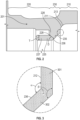
FIG. 2 is an enlarged side view of a portion of a split case of a portion of a compressor section of the gas turbine engine ofFIG. 1 in accordance with embodiments; -
FIG. 3 is an enlarged side view of the encircled portion ofFIG. 2 in accordance with embodiments; and -
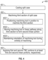
FIG. 4 is a flow diagram illustrating a split case formation method in accordance with embodiments. - These and other advantages and features will become more apparent from the following description taken in conjunction with the drawings.
- A detailed description of one or more embodiments of the disclosed apparatus and method are presented herein by way of exemplification and not limitation with reference to the Figures.
-
FIG. 1 schematically illustrates agas turbine engine 20. Thegas turbine engine 20 is disclosed herein as a two-spool turbofan that generally incorporates afan section 22, acompressor section 24, acombustor section 26 and aturbine section 28. Alternative engines might include other systems or features. Thefan section 22 drives air along a bypass flow path B in a bypass duct, while thecompressor section 24 drives air along a core flow path C for compression and communication into thecombustor section 26 and then expansion through theturbine section 28. Although depicted as a two-spool turbofan gas turbine engine in the disclosed non-limiting embodiment, it should be understood that the concepts described herein are not limited to use with two-spool turbofans as the teachings may be applied to other types of turbine engines including three-spool architectures. - The exemplary
gas turbine engine 20 generally includes alow speed spool 30 and ahigh speed spool 32 mounted for rotation about an engine central longitudinal axis A relative to an enginestatic structure 36 viaseveral bearing systems 38. It should be understood thatvarious bearing systems 38 at various locations may alternatively or additionally be provided, and the location ofbearing systems 38 may be varied as appropriate to the application. - The
low speed spool 30 generally includes aninner shaft 40 that interconnects afan 42, alow pressure compressor 44 and alow pressure turbine 46. Theinner shaft 40 is connected to thefan 42 through a speed change mechanism, which in exemplarygas turbine engine 20 is illustrated as a gearedarchitecture 48 to drive thefan 42 at a lower speed than thelow speed spool 30. Thehigh speed spool 32 includes anouter shaft 50 that interconnects ahigh pressure compressor 52 andhigh pressure turbine 54. Acombustor 56 is arranged in thegas turbine engine 20 between thehigh pressure compressor 52 and thehigh pressure turbine 54. The enginestatic structure 36 is arranged generally between thehigh pressure turbine 54 and thelow pressure turbine 46. The enginestatic structure 36 further supports thebearing systems 38 in theturbine section 28. Theinner shaft 40 and theouter shaft 50 are concentric and rotate viabearing systems 38 about the engine central longitudinal axis A which is collinear with their longitudinal axes. - The core airflow is compressed by the
low pressure compressor 44 and then thehigh pressure compressor 52, is mixed and burned with fuel in thecombustor 56 and is then expanded over thehigh pressure turbine 54 and thelow pressure turbine 46. The high andlow pressure turbines low speed spool 30 and thehigh speed spool 32, respectively, in response to the expansion. It will be appreciated that each of the positions of thefan section 22,compressor section 24,combustor section 26,turbine section 28, and fandrive gear system 48 may be varied. For example, gearedarchitecture 48 may be located aft of thecombustor section 26 or even aft of theturbine section 28, and thefan section 22 may be positioned forward or aft of the location of gearedarchitecture 48. - Currently, casings for the
compressor section 24 in particular include an air seal hook of a split case, which has a TBC applied to it. It has been found, however, that since a side of the split case has a first surface that has both vertical and curved portions as well as a second surface that is angled and forms a shallow angle with the vertical portion of the first surface, the machining process that forms the second surface tends to be executed such that subsequent coating processes form a burr or cusp at the shallow angle. The machining process in question involves a machining tool, which is used to machine the second surface, having to be rotated as the machining tool approaches the shallow angle This rotation results in a rounded-off portion of the second surface. - Accordingly, a need exists for a compressor section casing that has a split case that can be coated with TBC or other similar materials without forming a burr or cusp at an angle between surfaces.
- Therefore, as will be described below, a compressor section casing that has a split case is provided with two surfaces that forming a relatively large angle in order to improve TBC coatability and avoid the formation of a burr or cusp at the angle. The resulting TBC has a smooth appearance with a desired quality. The relatively large angle is limited by a need to maintain a thickness of a portion of the split case with a hook feature.
- With reference to
FIGS. 2 and 3 , asplit case 201 is provided for use in a casing of a compressor, such as thecompressor section 24 ofFIG. 1 . Thesplit case 201 includes afirst section 210, asecond section 220 and athird section 230. Thefirst section 210 includes aninterior surface 211 with a first linear portion 212 (seeFIG. 3 ). The firstlinear portion 212 can be oriented substantially along a radial dimension (i.e., vertical in the image ofFIG. 2 ) or, in some cases, oriented short of the radial dimension in the aft direction. Theinterior surface 211 can further include acurvilinear portion 213 that extends curvilinearly from an outboard end of the firstlinear portion 212. Thesecond section 220 includes ahook 225. - The
third section 230 is axially interposed between thefirst section 210 and thesecond section 220 and includes aninterior surface 235 with a second linear portion 236 (seeFIG. 3 ). The secondlinear portion 236 intersects with and forms a first angle α with the firstlinear portion 212. In accordance with embodiments, the first angle α is a simple angle that does not exhibit a burr or cusp in that the first angle α is formed only by proximal straight ends of the firstlinear portion 212 and the second linear portion 236 (i.e., there is an absence of a burr or cusp formed at an intersection point P (seeFIG. 3 ) of the firstlinear portion 212 and the second linear portion 236). - As shown in
FIG. 3 , thesplit case 201 can further include afirst TBC portion 301 applied to the firstlinear portion 212 and asecond TBC portion 302 applied to the secondlinear portion 236. In these or other cases, a magnitude of the first angle α is established such that thefirst TBC portion 301 and thesecond TBC portion 302 cooperatively form a second angle β that is substantially equal to the first angle α owing to the first angle α being the simple angle that does not exhibit a burr or cusp. In accordance with embodiments, the first angle α can have a magnitude of about 120°. - The
hook 225 includes aradial section 226 and anaxial section 227 extending away from first angle α from an inboard end of theradial section 226. A distance D between aninterior corner 228 of thehook 225 and the secondlinear portion 236 should exceed a thickness T of theaxial section 227. This effectively limits an upper magnitude of the first angle α. - With reference to
FIG. 4 , a splitcase formation method 400 is provided and includes casting a split case (block 401) such that the split case includes first, second and third sections, the first section including an interior surface with a first linear portion, the second section including a hook and the third section being interposed between the first and second sections, and machining the third section (block 402) to form an interior surface with a second linear portion such that the second linear portion intersects and forms a simple angle with the first linear portion at an intersection point of the first and second linear portions. The machining ofblock 402 can include positioning a machining tool in position to machine the third section (block 4021), moving the machining tool in a linear pathway along the third section to form the second linear portion (block 4022) and maintaining an orientation of the machining tool during an entirety of the machining (block 4023). In accordance with embodiments, the splitcase formation method 400 can further include applying first and second thermal barrier coating (TBC) portions to at least the first and second linear portions, respectively (block 403). - Benefits of the features described herein are the provision of a split case that meets minimum thickness requirements while removing the chance of forming a burr or cusp which can negatively impact a formation of a TBC.
- The term "about" is intended to include the degree of error associated with measurement of the particular quantity based upon the equipment available at the time of filing the application.
- The terminology used herein is for the purpose of describing particular embodiments only and is not intended to be limiting of the present disclosure. As used herein, the singular forms "a", "an" and "the" are intended to include the plural forms as well, unless the context clearly indicates otherwise. It will be further understood that the terms "comprises" and/or "comprising," when used in this specification, specify the presence of stated features, integers, steps, operations, elements, and/or components, but do not preclude the presence or addition of one or more other features, integers, steps, operations, element components, and/or groups thereof.
- While the present disclosure has been described with reference to an exemplary embodiment or embodiments, it will be understood by those skilled in the art that various changes may be made and equivalents may be substituted for elements thereof without departing from the scope of the present disclosure. In addition, many modifications may be made to adapt a particular situation or material to the teachings of the present disclosure without departing from the essential scope thereof. Therefore, it is intended that the present disclosure not be limited to the particular embodiment disclosed as the best mode contemplated for carrying out this present disclosure, but that the present disclosure will include all embodiments falling within the scope of the claims.
Claims (15)
- A split case, comprising:a first section (210) comprising an interior surface (211) with a first linear portion (212);a second section (220) comprising a hook (225);a third section (230) interposed between the first and second sections (210, 220) and comprising an interior surface (235) with a second linear portion (236) intersecting and forming a first angle (α) with the first linear portion (212); andfirst and second thermal barrier coating portions (301, 302) applied to at least the first and second linear portions (212, 236), respectively, a magnitude of the first angle (α) being established such that the first and second thermal barrier coating portions (301, 302) form a second angle (β) substantially equal to the first angle (α).
- The split case according to claim 1, wherein there is an absence of a cusp formed at an intersection point (P) of the first and second linear portions (212, 236).
- The split case according to claim 1 or 2, wherein the first angle (α) has a magnitude of about 120°.
- The split case according to any preceding claim, wherein the first linear portion (212) is oriented substantially along a radial dimension.
- The split case according to claim 4, wherein the first linear portion (212) is oriented short of the radial dimension.
- The split case according to any preceding claim, wherein the interior surface (211) of the first section (210) has a curvilinear portion (213) which extends from the first linear portion (212).
- The split case according to any preceding claim, wherein the hook (225) comprises a radial section (226) and an axial section (227) extending away from the first angle (α) from an inboard end of the radial section (226), optionally wherein a distance (D) between an interior corner (228) of the hook (225) and the second linear portion (236) exceeds a thickness of the axial section (227).
- A split case, comprising:a first section (210) comprising an interior surface (211) with a first linear portion (212);a second section (220) comprising a hook (225); anda third section (230) interposed between the first and second sections (210; 220) and comprising an interior surface (235) with a second linear portion (236) intersecting and forming a simple angle (α) with the first linear portion (212) at an intersection point (P) of the first and second linear portions (212, 236).
- The split case according to claim 8, wherein there is an absence of a cusp formed at the intersection point (P) and/or the simple angle (α) has a magnitude of about 120°.
- The split case according to claim 8 or 9, wherein the first linear portion (212) is oriented substantially along a radial dimension, optionally wherein the first linear portion (212) is oriented short of the radial dimension.
- The split case according to any of claims 8 to 10, wherein the hook (225) comprises a radial section (226) and an axial section (227) extending away from the simple angle (α) from an inboard end of the radial section (226), optionally wherein a distance (D) between an interior corner (228) of the hook (225) and the second linear portion (236) exceeds a thickness of the axial section (227).
- The split case according to any of claims 8 to 11, wherein:
the split case (201) further comprises first and second thermal barrier coating portions (301, 302) applied to at least the first and second linear portions (212, 236), respectively; and/or
the interior surface (211) of the first section (210) has a curvilinear portion (213) which extends from the first linear portion (212). - A split case formation method, comprising:casting a split case (201) comprising first, second and third sections (210; 220; 230), the first section (210) comprising an interior surface (211) with a first linear portion (212), the second section (220) comprising a hook (225) and the third section (230) being interposed between the first and second sections (210; 220); andmachining the third section (230) to form an interior surface (235) with a second linear portion (236) such that the second linear portion (236) intersects and forms a simple angle (α) with the first linear portion (212) at an intersection point (P) of the first and second linear portions (212, 236).
- The split case formation method according to claim 13, wherein the machining comprises:positioning a machining tool in position to machine the third section (230);moving the machining tool in a linear pathway along the third section (230) to form the second linear portion (212, 236); andmaintaining an orientation of the machining tool during an entirety of the machining.
- The split case formation method according to claim 13 or 14, further comprising applying first and second thermal barrier coating portions (301, 302) to at least the first and second linear portions (212, 236), respectively.
Applications Claiming Priority (1)
| Application Number | Priority Date | Filing Date | Title |
|---|---|---|---|
| US18/540,525 US20250198306A1 (en) | 2023-12-14 | 2023-12-14 | Split case with coatable transistion feature |
Publications (1)
| Publication Number | Publication Date |
|---|---|
| EP4575185A1 true EP4575185A1 (en) | 2025-06-25 |
Family
ID=93924084
Family Applications (1)
| Application Number | Title | Priority Date | Filing Date |
|---|---|---|---|
| EP24219793.7A Pending EP4575185A1 (en) | 2023-12-14 | 2024-12-13 | Split case of a gas turbine engine with thermal barrier coating |
Country Status (2)
| Country | Link |
|---|---|
| US (2) | US20250198306A1 (en) |
| EP (1) | EP4575185A1 (en) |
Citations (5)
| Publication number | Priority date | Publication date | Assignee | Title |
|---|---|---|---|---|
| EP1362983A2 (en) * | 2002-05-15 | 2003-11-19 | General Electric Company | Ceramic turbine shroud |
| US7246996B2 (en) * | 2005-01-04 | 2007-07-24 | General Electric Company | Methods and apparatus for maintaining rotor assembly tip clearances |
| US20140030071A1 (en) * | 2012-07-27 | 2014-01-30 | Nicholas R. Leslie | Blade outer air seal for a gas turbine engine |
| EP2900978B1 (en) * | 2012-09-27 | 2017-11-01 | United Technologies Corporation | Compressor section comprising a seal hook mount structure with overlapped coating |
| US11021987B2 (en) * | 2019-05-15 | 2021-06-01 | Raytheon Technologies Corporation | CMC BOAS arrangement |
Family Cites Families (6)
| Publication number | Priority date | Publication date | Assignee | Title |
|---|---|---|---|---|
| US5645399A (en) | 1995-03-15 | 1997-07-08 | United Technologies Corporation | Gas turbine engine case coated with thermal barrier coating to control axial airfoil clearance |
| FR2829176B1 (en) * | 2001-08-30 | 2005-06-24 | Snecma Moteurs | STATOR CASING OF TURBOMACHINE |
| US6848885B1 (en) * | 2003-08-18 | 2005-02-01 | General Electric Company | Methods and apparatus for fabricating gas turbine engines |
| US7607885B2 (en) * | 2006-07-31 | 2009-10-27 | General Electric Company | Methods and apparatus for operating gas turbine engines |
| US9079245B2 (en) * | 2011-08-31 | 2015-07-14 | Pratt & Whitney Canada Corp. | Turbine shroud segment with inter-segment overlap |
| GB201610309D0 (en) * | 2016-06-14 | 2016-07-27 | Rolls Royce Plc | A semi-annular component and method of manufacture |
-
2023
- 2023-12-14 US US18/540,525 patent/US20250198306A1/en not_active Abandoned
-
2024
- 2024-12-13 EP EP24219793.7A patent/EP4575185A1/en active Pending
-
2025
- 2025-02-21 US US19/060,099 patent/US12590547B2/en active Active
Patent Citations (5)
| Publication number | Priority date | Publication date | Assignee | Title |
|---|---|---|---|---|
| EP1362983A2 (en) * | 2002-05-15 | 2003-11-19 | General Electric Company | Ceramic turbine shroud |
| US7246996B2 (en) * | 2005-01-04 | 2007-07-24 | General Electric Company | Methods and apparatus for maintaining rotor assembly tip clearances |
| US20140030071A1 (en) * | 2012-07-27 | 2014-01-30 | Nicholas R. Leslie | Blade outer air seal for a gas turbine engine |
| EP2900978B1 (en) * | 2012-09-27 | 2017-11-01 | United Technologies Corporation | Compressor section comprising a seal hook mount structure with overlapped coating |
| US11021987B2 (en) * | 2019-05-15 | 2021-06-01 | Raytheon Technologies Corporation | CMC BOAS arrangement |
Also Published As
| Publication number | Publication date |
|---|---|
| US12590547B2 (en) | 2026-03-31 |
| US20250198307A1 (en) | 2025-06-19 |
| US20250198306A1 (en) | 2025-06-19 |
Similar Documents
| Publication | Publication Date | Title |
|---|---|---|
| EP3208432B1 (en) | System and method for repairing an abradable material | |
| EP3318718A1 (en) | Fan for a gas turbine engine an corresponding method of securing fan blades to a rotor of a fan of a gas turbine engine | |
| EP3761129B1 (en) | Manufacturing airfoil with rounded trailing edge | |
| EP3354853A1 (en) | Turbine blade with slot film cooling | |
| EP2993303B1 (en) | Gas turbine engine component with film cooling hole with pocket | |
| EP4190557A1 (en) | Machining of ceramic matrix composite during preforming and partial densification | |
| EP3019715B1 (en) | Method to repair variable vanes | |
| US11143035B2 (en) | Angled tip rods | |
| US12601295B2 (en) | Support structure for bearing compartment | |
| US11773726B2 (en) | Angled tip rods | |
| US12590547B2 (en) | Split case with coatable transistion feature | |
| US20230278150A1 (en) | Machining of ceramic matrix composite during preforming and partial densification | |
| EP3599346B1 (en) | Airfoil with trailing edge rounding | |
| EP3333369A1 (en) | Fan blade having a tip assembly | |
| EP3486436B1 (en) | Ablatable shaft feature in a gas turbine engine | |
| EP4365413A1 (en) | Support structure and spring for bearing compartment | |
| EP4166760A1 (en) | Angled tip rods | |
| EP2986823B1 (en) | Airfoil component | |
| EP3789586B1 (en) | Aerodynamic element assembly for a gas turbine engine |
Legal Events
| Date | Code | Title | Description |
|---|---|---|---|
| PUAI | Public reference made under article 153(3) epc to a published international application that has entered the european phase |
Free format text: ORIGINAL CODE: 0009012 |
|
| STAA | Information on the status of an ep patent application or granted ep patent |
Free format text: STATUS: THE APPLICATION HAS BEEN PUBLISHED |
|
| AK | Designated contracting states |
Kind code of ref document: A1 Designated state(s): AL AT BE BG CH CY CZ DE DK EE ES FI FR GB GR HR HU IE IS IT LI LT LU LV MC ME MK MT NL NO PL PT RO RS SE SI SK SM TR |
|
| STAA | Information on the status of an ep patent application or granted ep patent |
Free format text: STATUS: REQUEST FOR EXAMINATION WAS MADE |
|
| 17P | Request for examination filed |
Effective date: 20251215 |