EP4575177A1 - A fluid production data acquisition method in a well and related data acquisition system - Google Patents
A fluid production data acquisition method in a well and related data acquisition system Download PDFInfo
- Publication number
- EP4575177A1 EP4575177A1 EP23307261.0A EP23307261A EP4575177A1 EP 4575177 A1 EP4575177 A1 EP 4575177A1 EP 23307261 A EP23307261 A EP 23307261A EP 4575177 A1 EP4575177 A1 EP 4575177A1
- Authority
- EP
- European Patent Office
- Prior art keywords
- distributed
- production
- sensing data
- well
- fluid
- Prior art date
- Legal status (The legal status is an assumption and is not a legal conclusion. Google has not performed a legal analysis and makes no representation as to the accuracy of the status listed.)
- Pending
Links
Images



Classifications
-
- E—FIXED CONSTRUCTIONS
- E21—EARTH OR ROCK DRILLING; MINING
- E21B—EARTH OR ROCK DRILLING; OBTAINING OIL, GAS, WATER, SOLUBLE OR MELTABLE MATERIALS OR A SLURRY OF MINERALS FROM WELLS
- E21B47/00—Survey of boreholes or wells
- E21B47/12—Means for transmitting measuring-signals or control signals from the well to the surface, or from the surface to the well, e.g. for logging while drilling
- E21B47/13—Means for transmitting measuring-signals or control signals from the well to the surface, or from the surface to the well, e.g. for logging while drilling by electromagnetic energy, e.g. radio frequency
- E21B47/135—Means for transmitting measuring-signals or control signals from the well to the surface, or from the surface to the well, e.g. for logging while drilling by electromagnetic energy, e.g. radio frequency using light waves, e.g. infrared or ultraviolet waves
-
- E—FIXED CONSTRUCTIONS
- E21—EARTH OR ROCK DRILLING; MINING
- E21B—EARTH OR ROCK DRILLING; OBTAINING OIL, GAS, WATER, SOLUBLE OR MELTABLE MATERIALS OR A SLURRY OF MINERALS FROM WELLS
- E21B17/00—Drilling rods or pipes; Flexible drill strings; Kellies; Drill collars; Sucker rods; Cables; Casings; Tubings
- E21B17/20—Flexible or articulated drilling pipes, e.g. flexible or articulated rods, pipes or cables
- E21B17/206—Flexible or articulated drilling pipes, e.g. flexible or articulated rods, pipes or cables with conductors, e.g. electrical, optical
-
- E—FIXED CONSTRUCTIONS
- E21—EARTH OR ROCK DRILLING; MINING
- E21B—EARTH OR ROCK DRILLING; OBTAINING OIL, GAS, WATER, SOLUBLE OR MELTABLE MATERIALS OR A SLURRY OF MINERALS FROM WELLS
- E21B43/00—Methods or apparatus for obtaining oil, gas, water, soluble or meltable materials or a slurry of minerals from wells
- E21B43/12—Methods or apparatus for controlling the flow of the obtained fluid to or in wells
-
- E—FIXED CONSTRUCTIONS
- E21—EARTH OR ROCK DRILLING; MINING
- E21B—EARTH OR ROCK DRILLING; OBTAINING OIL, GAS, WATER, SOLUBLE OR MELTABLE MATERIALS OR A SLURRY OF MINERALS FROM WELLS
- E21B43/00—Methods or apparatus for obtaining oil, gas, water, soluble or meltable materials or a slurry of minerals from wells
- E21B43/14—Obtaining from a multiple-zone well
-
- E—FIXED CONSTRUCTIONS
- E21—EARTH OR ROCK DRILLING; MINING
- E21B—EARTH OR ROCK DRILLING; OBTAINING OIL, GAS, WATER, SOLUBLE OR MELTABLE MATERIALS OR A SLURRY OF MINERALS FROM WELLS
- E21B47/00—Survey of boreholes or wells
- E21B47/10—Locating fluid leaks, intrusions or movements
- E21B47/103—Locating fluid leaks, intrusions or movements using thermal measurements
-
- E—FIXED CONSTRUCTIONS
- E21—EARTH OR ROCK DRILLING; MINING
- E21B—EARTH OR ROCK DRILLING; OBTAINING OIL, GAS, WATER, SOLUBLE OR MELTABLE MATERIALS OR A SLURRY OF MINERALS FROM WELLS
- E21B47/00—Survey of boreholes or wells
- E21B47/10—Locating fluid leaks, intrusions or movements
- E21B47/107—Locating fluid leaks, intrusions or movements using acoustic means
Definitions
- the method is in particular intended to carry out well production logging to determine production information in a fluid production well, such as an oil and/or gas producing well.
- Well production logging is in particular carried out to determine an allocation of fluid production among the different production zones. Knowing this allocation is an asset in monitoring and optimizing fluid production of the well. More generally, there is a requirement for well production data to improve reservoir performance models and operations.
- Well production data is generally acquired using production logging tools (PLT tools) carried by a tool string attached at the bottom of a reinforced electrical cable.
- PKT tools production logging tools
- These tools have been used for over fifty years and comprise a mechanical spinner which rotates with wellbore fluids passing the spinner blades.
- the fluid flow velocity is calculated from the rotation speed. Additionally, pressure and temperature measurements are provided within the tools.
- a limitation of the PLT tools is that under high flow rates well flowing conditions the tool can be lifted by the flow, causing compression and damage to the cable which is used to deploy the tool down the well. In worst case, the lifting issue can cause knotting the cable, blocking the well and requiring fishing operations to remove the tool.
- SPE-205435-MS discloses a well production data acquisition method, in which a PLT tool is lowered in a well using a wireline with built-in optic fibers.
- the acquisition method comprises two phases.
- a regular production logging acquisition is carried out with the PLT tool while the electrical lines of the cable are connected to a surface wireline acquisition system.
- This phase allows for the execution of a standard production logging program.
- the tool string comprising the PLT tool is lowered all the way down to the bottom of the well, and the optical lines are connected to distributed temperature sensing (DTS) and distributed acoustic sensing (DAS) boxes to acquire DTS and DAS data.
- DTS distributed temperature sensing
- DAS distributed acoustic sensing
- Such a method is not entirely satisfactory. It requires an electrical cable wireline which is moreover equipped with a optic fiber. The manufacturing and operation costs of such a wireline are high. Very specific equipment is required to ensure appropriate sealing around the cable at the wellhead.
- One aim of the invention is thus to provide a simpler and cheaper to operate acquisition method to collect well production data, the collected data allowing a simpler data processing to obtain valuable production information.
- the subject matter of the invention is a fluid production data acquisition method of the above-mentioned type, characterized in that lowering of the distributed optic fiber sensor comprises deploying a slickline containing the distributed optic fiber sensor in at least a producing zone of the well to acquire the distributed temperature sensing data and distributed acoustic sensing data, and lifting back the slickline after acquiring the distributed temperature sensing data and distributed acoustic sensing data.
- the method according to the invention may comprise one or more of the following feature(s), taken solely, or according to any technical feasible combination:
- the invention also concerns a fluid production data acquisition system in a well comprising:
- a fluid production data acquisition method according to the invention is carried out with a data acquisition system 10 shown schematically in figure 1 .
- the fluid production data is acquired in a well 12 of a fluid production installation 14.
- the fluid production installation 14 is here located onshore, with the well 12 emerging in the atmosphere at the surface of the ground 16.
- the fluid production installation 14 is located offshore, the well 12 emerging from the ground 16 at the bottom of a body of water and being connected to a surface installation 19 via fluid transportation pipes (often referred to as "risers").
- the well 12 extends between a reservoir 18 located in the ground 16, to a surface installation 19.
- the well 12 is schematically represented as vertical.
- the well 12 comprise inclined sections, and/or horizontal sections, and/or several branches.
- the well 12 delimits a borehole 20 bored in the ground 16 between the reservoir 18 and the surface of the ground 16.
- the well 12 comprises at least a casing 22 lining at least the upper part of the borehole 20 and a completion comprising a production tubing 24 and flow control devices 26 configured to operate the well 12 between a well shut-in configuration, in which fluid production from the reservoir 18 to the surface is stopped, and several production configurations, at various fluid production flow rates and/or from selectively one or several production zones 24A to 24D.
- the production tubing 24 emerges at a lower end located above several staged production zones 24A to 24D in fluid communication with the reservoir 18.
- the production zones 24A to 24B are for example communicating with the borehole 20 through perforations in the casing 22 and/or through direct open hole communication, in the absence of casing 22.
- the well 12 extends down to a sump 27 located below the production zones 24A to 24D, with no fluid production occurring in the sump 27.
- the sump 27 has a hold-up depth 28 ("HUD”), at which point, a tool inserted into the well 12 cannot be further lowered.
- HUD hold-up depth
- the surface installation 19 of the well 12 comprises a wellhead 30, equipped with a sealing interface (not shown), for example a blowout preventer, which allows the introduction of an intervention line in the well 12 while preserving sealing around the intervention line.
- a sealing interface for example a blowout preventer
- the wellhead 30 is located at the surface.
- the wellhead 30 is located at the bottom of the body of water or in a surface installation 19.
- the wellhead is also connected to a produced fluid collector or/and to a fluid processing installation.
- the data acquisition system 10 comprises a slickline 40, equipped with a distributed optic fiber sensor (DFOS) 42 (shown in figure 2 ), a tool string 44, advantageously attached to a bottom end of the slickline 40 (see figure 1 ), and a deploying system 46, to allow deployment of the slickline 40 carrying the tool string 44 in the well 12, down to the sump 27, and the retrieving of the slickline 40 out of the well 12.
- DFOS distributed optic fiber sensor
- the data acquisition system 10 further comprises a surface optical acquisition device 47, connected to the distributed optic fiber sensor 42 of the slickline 40. It also comprises a distributed temperature sensing (DTS) data and a distributed acoustic sensing (DAS) data analyzer 48 to receive data from the distributed optic fiber sensor 42 and process the data to determine fluid production information, for example allocation of fluid production among the different production zones 24A to 24B.
- DTS distributed temperature sensing
- DAS distributed acoustic sensing
- the slickline 40 comprises an outer metal tube 50, an inner protection tube 52 containing the distributed optic fiber sensor 42, and in this example, a reinforcing layer 54 and an intermediate sheath 56 positioned between the outer tube 50 and the inner tube 52.
- the slickline 40 further advantageously comprises an inner gel layer 58 in which the distributed optic fiber sensor 42 is embedded.
- the outer tube 50 has an external smooth surface 60 along its whole length.
- the smooth surface 60 facilitates the tight insertion of the slickline 40 in the well 12 through the wellhead 30.
- the outer diameter of the outer tube 50 is generally greater than 2 mm, and is comprised for example between 2 mm and 10 mm, preferably from 3 mm to 7 mm.
- the inner tube 52 tightly confines the distributed optic fiber sensor 42 at the center of the slickline 40. It is generally made of metal. It defines an inner space in which the distributed optic fiber sensor 42 and advantageously the gel layer 58 are tightly contained.
- the reinforcing layer 54 comprises a plurality of reinforcing wires 64 preferably made of metal.
- the reinforcing layer 54 increases the tensile resistance of the slickline 40 to allow its introduction and removal, even at well depths greater than 5500 m.
- the intermediate sheath 56 when present, tightens the reinforcing layer 54 and maintains its structure. It is for example made of a metal tube.
- the distributed optic fiber sensor 42 comprises at least a single mode optic fiber and/or at least a multimode optic fiber.
- the distributed optic fiber sensor 42 comprises at least a multi-mode optic fiber 66A to collect distributed temperature sensing (DTS) data at successive positions along the well 12 and at least a single mode optic fiber 66B to collect distributed acoustic sensor (DAS) data at successive positions along the well 12.
- DTS distributed temperature sensing
- DAS distributed acoustic sensor
- the optic fibers 66A, 66B preferably extend along substantially the whole length of the slickline 40.
- the optic fiber 66A is configured to measure data representative of temperature at successive positions along the length of the optic fiber 66A, for example every 1 m.
- the optic fiber 66B is configured to measure data representative of acoustic noise at successive positions along the length of the optic fiber 66B, for example every 2.5 m.
- the tool string 44 is carried at the bottom end of the slickline 40. It generally comprises a weighing body 70 to generate tension on the slickline 40 when the slickline 40 is deployed in the well 12. It optionally comprises rollers 72 to ease the movement of the tool string 44 within the well, in particular in inclined or horizontal sections.
- the tool string 44 advantageously comprises a pressure sensor 74A and a temperature sensor 74B to measure respectively the local pressure and temperature of the fluid within the well 12. It is however without a flow measuring device, in particular without a flow measuring device having a mobile probe, in particular a spinner.
- the deploying system 46 for example comprises a winch and a controller to control the lowering of the slickline 40 and of the tool string 44 in the well 12 down to the sump 27 and the lifting back of the slickline 40 and the tool string 44 up to the surface installation 19.
- the optical acquisition device 47 comprises at least a laser source configured to inject a light wave in each of the optic fibers 66A, 66B and an analyzer, configured to measure back scattered light resulting from a reflection of the injected light wave at various positions along the optic fibers 66A, 66B to generate distributed temperature sensing data from the fiber 66A, and distributed acoustic sensing data from the optic fiber 66B.
- the distributing temperature sensing data and distributed acoustic sensing data analyzer 48 for example comprises at least a processor 80 and a memory 82 containing software modules to be executed by the processor 80.
- the analyzer 48 comprises a field programmable gate array or an application specific integrated circuit configured to carry out the functionalities of the modules which will be described below.
- the analyzer 48 is represented in the vicinity of the well 12 in the fluid production installation 14. In a variant, the analyzer 48 is located remote from the fluid production installation 14 and connected to the optical acquisition device 47 via a data transmission network.
- the analyzer 48 comprises at least a temperature profile determining module 84, configured to obtain at each measurement time, a temperature profile along depth of fluid contained in the well 12 from distributed temperature sensor data collected by the optical acquisition device 47.
- the analyzer 48 also comprises a distributed acoustic sensing data analyzing module 86, to determine an acoustic emission profile as a function of depth and optionally frequency, in order to determine positions of fluid production regions within the well 12 and advantageously a type of production (direct from a formation, from a valve, from a perforation etc.) from the distributed acoustic sensing data.
- a distributed acoustic sensing data analyzing module 86 to determine an acoustic emission profile as a function of depth and optionally frequency, in order to determine positions of fluid production regions within the well 12 and advantageously a type of production (direct from a formation, from a valve, from a perforation etc.) from the distributed acoustic sensing data.
- the analyzer 48 further comprises a thermal modeling simulator 88, configured to fit the temperature profile determined by the temperature profile determining module 84 to a simulated temperature profile calculated from adjustable production parameters including productions zones locations, produced fluid composition and flow rates at each production zone, and from well characterization data, such as well schematic and trajectory, ground thermal profile, thermophysical rock properties and reservoir and fluid parameters, to provide a fluid production allocation among the production zones 24A to 24B of the well 12.
- a thermal modeling simulator 88 configured to fit the temperature profile determined by the temperature profile determining module 84 to a simulated temperature profile calculated from adjustable production parameters including productions zones locations, produced fluid composition and flow rates at each production zone, and from well characterization data, such as well schematic and trajectory, ground thermal profile, thermophysical rock properties and reservoir and fluid parameters, to provide a fluid production allocation among the production zones 24A to 24B of the well 12.
- the method first comprises a step 100 of lowering the slickline 40 containing the distributed optic fiber sensor 42 and jointly the tool string 44 carried at the bottom of the slickline 40 in the well 12.
- the slickline 40 is lowered at least down to the sump 27, to place the tool string 44 in the sump 27, above the hold-up depth 28.
- the tool string 44 thus hangs at the bottom of the slickline 40, to apply a tension thereon.
- the slickline 40 extends longitudinally and linearly in the well 12, down the production tubing 24 and then, out of the production tubing 24 along the fluid production zones 24A to 24D.
- the tool string 44 is immersed in the sump 27.
- the tool string 44 is thus out of the upward produced fluid flow generated by the production zones 24A to 24D.
- the slickline 40 offers minimal resistance to flow and thus higher flow rates of well production can be achieved during the data acquisition, without the risk of lifting the slickline 40.
- a step 102 of data acquisition is carried out.
- the acquisition device 47 acquires distributed temperature sensing data and distributed acoustic sensing data obtained from the optic fibers 66A, 66B of the distributed optic fiber sensor 42 at various positions along the well 12.
- data points can be obtained at successive depths with a resolution between 2 m and 4 m.
- FIG. 3 An example of measurement acquisition scheme is shown in figure 3 .
- the flow control devices 26 of the well 12 are first controlled to place the well 12 in a well shut-in a position, to acquire baseline data without fluid production in a phase 104 which can last for example between thirty minutes and two hours.
- phase 106 the flow control devices 26 of the well 12 are controlled to place the well 12 in a first production configuration at a first flow rate.
- a data acquisition phase 108 during the stabilization of the fluid production flow rate is carried out for a plurality of hours, for example from two hours to five hours and then another data acquisition phase 110 is carried out during a thermal equilibrium phase ranging from two hours to four hours, phase 110 being the main acquisition phase.
- the flow control devices 26 are again controlled to increase the production flow rate from the first production flow rate to a second production flow rate greater than the first production flow rate.
- phase 114 of stabilization of the flow which ranges from thirty minutes to three hours and then another data acquisition is carried out through a phase 116 of thermal equilibrium ranging from two hours to four hours.
- the flow control devices 26 are operated again in phase 118 to pass again the well in the well shut-in configuration.
- the method comprises lifting back the slickline 40 carrying the tool string 44 out of the well 12 to remove it from the borehole 20.
- the fluid production is not affected by the presence of the slickline 40.
- the or each laser of the optical acquisition device 47 continuously injects light pulses within the optic fibers 66A, 66B, and the analyzer of the optical acquisition device 47 continuously measures backscattered light resulting from backscattering at various lengths along the optic fibers 66A, 66B. Measured backscattered light forms distributed temperature sensing data and distributed acoustic sensing data.
- the analyzer 48 collects and stores distributed temperature sensing data and distributed acoustic sensing data obtained from the optical acquisition device 47 during the acquisition step 102.
- the temperature profile determining module 84 gathers distributed temperature sensing data obtained at each measurement time during the acquisition step 102 and calculates, for each measurement time, a fluid temperature versus depth curve along at least the production zones 24A to 24D.
- Figure 5 shows for example a first temperature profile 124 of temperature T versus depth D obtained from data acquired when the well 12 is in a well shut-in configuration, a second temperature profile 126 obtained from data acquired when the well 12 is producing at a first flow rate, and a third temperature profile 128 obtained from data acquired when the well 12 is producing at a second flow rate.
- the distributed acoustic sensing data analyzing module 86 calculates an acoustic emission profile relating the intensity of the measured acoustic data as a function of depth D and advantageously frequency F, as depicted in the distribution plot 132 visible in figure 5 .
- the analyzing module 86 identifies a position of a potential production zone 24A to 24D in which fluid from the reservoir 18 enters the borehole 20 of the well 12.
- the analyzing module 86 analyzes the acoustic signal intensity as a function of frequency at the potential production zone 24A to 24D to determine a production type at the potential production zone 24A to 24D.
- the production type is for example a production through a control valve, a production through a perforation, an open hole production from the reservoir 18, with a type of formation ranging for example from channels, fractures, large pores or tight formation.
- the classification among different production types is for example done by the analyzing module 86 using a frequency at maximum acoustic intensity or using a frequency range around a maximum acoustic intensity of the measured acoustic emission profile.
- the thermal model simulator 88 carries out successive thermal simulations of simulated temperature versus depth curves to fit a simulated temperature profile with each of the measured temperature profiles 124, 126, 128 obtained from distributed temperature sensing data, varying adjustable parameters of the thermal simulation until a convergence is obtained.
- the convergence is for example obtained when a difference between the simulated temperature profile 130 and the measured temperature profile 128 is less than a predefined threshold, for example less than 20%.
- the adjustable parameters include at least one parameter among positions of production zones 24A to 24D, production type at each production zone 24A to 24D, fluid production flow rate at each production zone 24A to 24D, fluid phase composition at each production zone 24A to 24D.
- the thermal simulations also use well characterization data, including at least one of well schematic and trajectory, ground thermal profile, thermophysical rock properties and reservoir and fluid data.
- the positions of the production zones 24A to 24D as well as the production type at each production zone 24A to 24D may be determined at least in part by the analyzer module 86, based on the measured distributed acoustic sensing data.
- the simulator uses thermal models based on thermodynamic factors that affect fluid flowing temperature, including Joule-Thomson effect, especially resulting from gas production, thermal mixing, adiabatic effect, gas liberation and convective/conductive heat exchange between reservoir fluid and surrounding rock and reservoir. Joule-Thomson effect and thermal mixing are the most affecting factors.
- FIG 4 Examples of simulated temperature profiles obtained from the simulator 88 are shown in figure 4 .
- the parameter varied in figure 4 is the phase composition of the produced fluid from production zone 24D.
- the production of a fluid formed of liquid oil increases the temperature of the fluid downstream of the production zone 24D
- the production of a fluid containing mostly gas decreases the temperature of the fluid downstream of the injection zone.
- the initial geothermal gradient 135 used as well characterization data is also depicted in figure 4 .
- the analyzer 48 uses the values of the adjustable parameters which correspond to the fitted simulated thermal profile 130, in particular the fluid production flow rates from each production zone 24A to 24D, to calculate an allocation of fluid production flow rate between the different production zones 24A to 24D.
- the allocated flow rates are calculated in percentage as a function of depth and in graph 142, the cumulated flow rates are calculated as a function of depth.
- the method according to the invention thus simplifies the collection of very valuable fluid production data in a well 12 at various depths along the well 12, without having to carry out a full production logging with a production logging tool.
- Very accurate allocation of produced fluid from different production zones 24A to 24D can thus be obtained in various production conditions.
Landscapes
- Engineering & Computer Science (AREA)
- Geology (AREA)
- Life Sciences & Earth Sciences (AREA)
- Mining & Mineral Resources (AREA)
- Physics & Mathematics (AREA)
- Environmental & Geological Engineering (AREA)
- Fluid Mechanics (AREA)
- General Life Sciences & Earth Sciences (AREA)
- Geochemistry & Mineralogy (AREA)
- Remote Sensing (AREA)
- Mechanical Engineering (AREA)
- Electromagnetism (AREA)
- Geophysics (AREA)
- Measuring Temperature Or Quantity Of Heat (AREA)
Abstract
The fluid production data acquisition method comprises :
- lowering a distributed optic fiber sensor in a well (12);
- acquiring distributed temperature sensing data and distributed acoustic sensing data via the distributed optic fiber sensor.
- lowering a distributed optic fiber sensor in a well (12);
- acquiring distributed temperature sensing data and distributed acoustic sensing data via the distributed optic fiber sensor.
Lowering of the distributed optic fiber sensor comprises deploying a slickline (40) containing the distributed optic fiber sensor in at least a producing zone (24A to 24D) of the well (12) to acquire the distributed temperature sensing data and distributed acoustic sensing data, and lifting back the slickline (40) after acquiring the distributed temperature sensing data and distributed acoustic sensing data.
Description
- The present invention concerns a fluid production data acquisition method in a well, comprising:
- lowering a distributed optic fiber sensor in a well ;
- acquiring distributed temperature sensing data and distributed acoustic sensing data via the distributed optic fiber sensor.
- The method is in particular intended to carry out well production logging to determine production information in a fluid production well, such as an oil and/or gas producing well.
- Fluid production in a well can arise from different production zones, located at various depths along the length of the well.
- Well production logging is in particular carried out to determine an allocation of fluid production among the different production zones. Knowing this allocation is an asset in monitoring and optimizing fluid production of the well. More generally, there is a requirement for well production data to improve reservoir performance models and operations.
- Well production data is generally acquired using production logging tools (PLT tools) carried by a tool string attached at the bottom of a reinforced electrical cable.
- These tools have been used for over fifty years and comprise a mechanical spinner which rotates with wellbore fluids passing the spinner blades. The fluid flow velocity is calculated from the rotation speed. Additionally, pressure and temperature measurements are provided within the tools.
- A limitation of the PLT tools is that under high flow rates well flowing conditions the tool can be lifted by the flow, causing compression and damage to the cable which is used to deploy the tool down the well. In worst case, the lifting issue can cause knotting the cable, blocking the well and requiring fishing operations to remove the tool.
- In addition, traditional methods based on a spinner may lead to imprecise and even sometimes flawed results if the spinner is clogged by residues such as particles and oily residues arising from the reservoir.
- In order to try to alleviate this problem, SPE-205435-MS discloses a well production data acquisition method, in which a PLT tool is lowered in a well using a wireline with built-in optic fibers.
- The acquisition method comprises two phases. In a first phase, a regular production logging acquisition is carried out with the PLT tool while the electrical lines of the cable are connected to a surface wireline acquisition system. This phase allows for the execution of a standard production logging program.
- In a second phase, the tool string comprising the PLT tool is lowered all the way down to the bottom of the well, and the optical lines are connected to distributed temperature sensing (DTS) and distributed acoustic sensing (DAS) boxes to acquire DTS and DAS data. The acquired DTS and DAS data are used into a machine learning software to match the measured PLT data.
- Such a method is not entirely satisfactory. It requires an electrical cable wireline which is moreover equipped with a optic fiber. The manufacturing and operation costs of such a wireline are high. Very specific equipment is required to ensure appropriate sealing around the cable at the wellhead.
- Moreover, the data processing is complex and may lead to uncertain results. A traditional PLT intervention must be carried out to obtain a good correlation, which is time consuming and expensive.
- One aim of the invention is thus to provide a simpler and cheaper to operate acquisition method to collect well production data, the collected data allowing a simpler data processing to obtain valuable production information.
- To this aim, the subject matter of the invention is a fluid production data acquisition method of the above-mentioned type, characterized in that lowering of the distributed optic fiber sensor comprises deploying a slickline containing the distributed optic fiber sensor in at least a producing zone of the well to acquire the distributed temperature sensing data and distributed acoustic sensing data, and lifting back the slickline after acquiring the distributed temperature sensing data and distributed acoustic sensing data.
- The method according to the invention may comprise one or more of the following feature(s), taken solely, or according to any technical feasible combination:
- the well comprises a sump below the or each producing zone, the slickline being lowered at least to the sump ;
- deploying the slickline comprises jointly deploying a tool string carried by a lower end of the slickline, the tool string being without a mobile flow measuring device, in particular without a spinner, the tool string being lowered in the sump ;
- the tool string comprises a pressure sensor and/or a temperature sensor, the method comprising acquiring pressure data with the pressure sensor and/or temperature data with the temperature sensor while lowering the tool string to the sump ;
- lowering the tool string in the sump comprises maintaining the tool string above the hold-up depth, the tool string hanging from the lower end of the slickline while acquiring distributed temperature sensing data and distributed acoustic sensing data ;
- the well comprises a completion comprising flow control devices, acquiring the distributed temperature sensing data and distributed acoustic sensing data including controlling the flow control devices to place the well in a well shut-in configuration and carrying out a first distributed temperature sensing data and distributed acoustic sensing data acquisition, then controlling the flow control devices to place the well in a first production configuration at a first fluid production flow rate, and carrying out a distributed temperature sensing data and distributed acoustic sensing data acquisition ;
- it comprises, after carrying out the second distributed temperature sensing data and distributed acoustic sensing data acquisition, controlling the flow control devices to place the well in a second production configuration at a second fluid production flow rate greater than the first fluid production flow rate in the first production configuration, and carrying out a third distributed temperature sensing data and distributed acoustic sensing data acquisition ;
- it comprises, after acquiring the distributed temperature sensing data and distributed acoustic sensing data, determining at least one of a position of a fluid producing zone in the well, a fluid production flow rate of the fluid producing zone or/and a fluid composition of the fluid produced at the fluid production zone using the distributed temperature sensing data and/or the distributed acoustic sensing data acquired with the distributed optic fiber sensor and using a thermal model simulator taking into account well characterization data, including at least one of well schematic and trajectory, ground thermal profile, thermophysical rock properties and/or reservoir and fluid data ;
- it comprises carrying out successive thermal simulations of simulated temperature profiles with the thermal model simulator to fit a simulated temperature profile with a measured temperature profile obtained from distributed temperature sensing data, by varying adjustable parameters of the thermal simulation including at least one of positions of production zones, type of production at each production zone, fluid production flow rate at each production zone, fluid phase composition at each production zone, and determining production information using the values of the adjustable parameters obtained when the simulated temperature profile fits the measured temperature profile ;
- it comprises using the distributed acoustic sensing data to determine a position of a fluid producing zone, the thermal model simulator using the determined position of a fluid producing zone to carry out the successive thermal simulations ;
- it comprises using the distributed acoustic sensing data to determine a production type at the production zone, the production type being for example a production through a control valve, a production through a perforation, an open hole production of the reservoir, the thermal model simulator using the determined production type at the production zone to carry out the successive thermal simulations ;
- the determining production data is carried out without using acquired production logging tool data acquired with a production logging tool comprising a mobile flow measuring device, in particular a spinner ;
- the slickline has an outer tube having a smooth surface, and an inner protection tube containing the distributed optic fiber sensor;
- the outer tube and the inner protection tube delimit an intermediate annular space containing at least a reinforcing layer.
- The invention also concerns a fluid production data acquisition system in a well comprising:
- a distributed optic fiber sensor configured to be introduced in the well ;
- an optical acquisition device configured to acquiring distributed temperature sensing data and distributed acoustic sensing data via the distributed optic fiber sensor ;
- The invention will be better understood, based on the following description, given purely as an example, and made in reference to the appended drawings, in which:
-
figure 1 is a schematic view of a well equipped with a production data acquisition system to carry out a fluid production data acquisition method according to the invention; -
figure 2 is a side view and cross sectional view of a slickline used to carry out the method according to the invention; -
figure 3 is a schematic flowchart of successive phases of a data acquisition step of the method according to the invention; -
figure 4 is a schematic view of simulated temperature profiles of fluid temperature versus depth in a well producing various types of fluids from a given production zone at a given flow rate, produced by a thermal model simulator used in the method according to the invention ; -
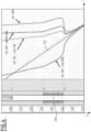
figure 5 is a view of (a) measured temperature profiles obtained from distributed temperature sensing data acquired while the well is not producing, while the well is producing at a first flow rate and at a second flow rate, in comparison with a simulated temperature profile obtained from the thermal model simulator by fitting to the measured temperature profile, (b) related distributed acoustic data used to determine the location of production zones in the well, and (c) allocation information obtained from fitting the simulated temperature profile with the measured temperature profile; -
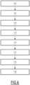
figure 6 is a schematic flowchart of a fluid production data acquisition method according to the invention. - A fluid production data acquisition method according to the invention is carried out with a
data acquisition system 10 shown schematically infigure 1 . - The fluid production data is acquired in a well 12 of a
fluid production installation 14. Thefluid production installation 14 is here located onshore, with the well 12 emerging in the atmosphere at the surface of theground 16. - In a variant (not shown), the
fluid production installation 14 is located offshore, the well 12 emerging from theground 16 at the bottom of a body of water and being connected to asurface installation 19 via fluid transportation pipes (often referred to as "risers"). - The
well 12 extends between areservoir 18 located in theground 16, to asurface installation 19. In the example offigure 1 , thewell 12 is schematically represented as vertical. In variants (not shown), the well 12 comprise inclined sections, and/or horizontal sections, and/or several branches. - The
well 12 delimits aborehole 20 bored in theground 16 between thereservoir 18 and the surface of theground 16. - The
well 12 comprises at least acasing 22 lining at least the upper part of theborehole 20 and a completion comprising aproduction tubing 24 andflow control devices 26 configured to operate thewell 12 between a well shut-in configuration, in which fluid production from thereservoir 18 to the surface is stopped, and several production configurations, at various fluid production flow rates and/or from selectively one orseveral production zones 24A to 24D. - In the example of
figure 1 , theproduction tubing 24 emerges at a lower end located above several stagedproduction zones 24A to 24D in fluid communication with thereservoir 18. - The
production zones 24A to 24B are for example communicating with theborehole 20 through perforations in thecasing 22 and/or through direct open hole communication, in the absence ofcasing 22. - The well 12 extends down to a
sump 27 located below theproduction zones 24A to 24D, with no fluid production occurring in thesump 27. - The
sump 27 has a hold-up depth 28 ("HUD"), at which point, a tool inserted into the well 12 cannot be further lowered. - The
surface installation 19 of the well 12 comprises awellhead 30, equipped with a sealing interface (not shown), for example a blowout preventer, which allows the introduction of an intervention line in the well 12 while preserving sealing around the intervention line. - In the
onshore installation 14 represented infigure 1 , thewellhead 30 is located at the surface. In an offshore installation, thewellhead 30 is located at the bottom of the body of water or in asurface installation 19. The wellhead is also connected to a produced fluid collector or/and to a fluid processing installation. - The
data acquisition system 10 comprises aslickline 40, equipped with a distributed optic fiber sensor (DFOS) 42 (shown infigure 2 ), atool string 44, advantageously attached to a bottom end of the slickline 40 (seefigure 1 ), and a deployingsystem 46, to allow deployment of theslickline 40 carrying thetool string 44 in the well 12, down to thesump 27, and the retrieving of theslickline 40 out of the well 12. - The
data acquisition system 10 further comprises a surfaceoptical acquisition device 47, connected to the distributedoptic fiber sensor 42 of theslickline 40. It also comprises a distributed temperature sensing (DTS) data and a distributed acoustic sensing (DAS)data analyzer 48 to receive data from the distributedoptic fiber sensor 42 and process the data to determine fluid production information, for example allocation of fluid production among thedifferent production zones 24A to 24B. - An example of
slickline 40 is shown infigure 2 . Theslickline 40 comprises anouter metal tube 50, aninner protection tube 52 containing the distributedoptic fiber sensor 42, and in this example, a reinforcinglayer 54 and anintermediate sheath 56 positioned between theouter tube 50 and theinner tube 52. - The
slickline 40 further advantageously comprises aninner gel layer 58 in which the distributedoptic fiber sensor 42 is embedded. - The
outer tube 50 has an externalsmooth surface 60 along its whole length. Thesmooth surface 60 facilitates the tight insertion of theslickline 40 in the well 12 through thewellhead 30. - The outer diameter of the
outer tube 50 is generally greater than 2 mm, and is comprised for example between 2 mm and 10 mm, preferably from 3 mm to 7 mm. - The
inner tube 52 tightly confines the distributedoptic fiber sensor 42 at the center of theslickline 40. It is generally made of metal. It defines an inner space in which the distributedoptic fiber sensor 42 and advantageously thegel layer 58 are tightly contained. - It also defines an outer intermediate annular space with the
outer tube 50, containing the reinforcinglayer 54 and advantageously theintermediate sheath 56. - The reinforcing
layer 54 comprises a plurality of reinforcingwires 64 preferably made of metal. The reinforcinglayer 54 increases the tensile resistance of theslickline 40 to allow its introduction and removal, even at well depths greater than 5500 m. - The
intermediate sheath 56, when present, tightens the reinforcinglayer 54 and maintains its structure. It is for example made of a metal tube. - The distributed
optic fiber sensor 42 comprises at least a single mode optic fiber and/or at least a multimode optic fiber. In the example offigure 2 , the distributedoptic fiber sensor 42 comprises at least a multi-modeoptic fiber 66A to collect distributed temperature sensing (DTS) data at successive positions along the well 12 and at least a singlemode optic fiber 66B to collect distributed acoustic sensor (DAS) data at successive positions along thewell 12. - The
optic fibers slickline 40. When connected to theacquisition device 47, theoptic fiber 66A is configured to measure data representative of temperature at successive positions along the length of theoptic fiber 66A, for example every 1 m. Theoptic fiber 66B is configured to measure data representative of acoustic noise at successive positions along the length of theoptic fiber 66B, for example every 2.5 m. - The
tool string 44 is carried at the bottom end of theslickline 40. It generally comprises a weighingbody 70 to generate tension on theslickline 40 when theslickline 40 is deployed in thewell 12. It optionally comprisesrollers 72 to ease the movement of thetool string 44 within the well, in particular in inclined or horizontal sections. - The
tool string 44 advantageously comprises apressure sensor 74A and atemperature sensor 74B to measure respectively the local pressure and temperature of the fluid within thewell 12. It is however without a flow measuring device, in particular without a flow measuring device having a mobile probe, in particular a spinner. - The deploying
system 46 for example comprises a winch and a controller to control the lowering of theslickline 40 and of thetool string 44 in the well 12 down to thesump 27 and the lifting back of theslickline 40 and thetool string 44 up to thesurface installation 19. - The
optical acquisition device 47 comprises at least a laser source configured to inject a light wave in each of theoptic fibers optic fibers fiber 66A, and distributed acoustic sensing data from theoptic fiber 66B. - The distributing temperature sensing data and distributed acoustic sensing data analyzer 48 for example comprises at least a
processor 80 and amemory 82 containing software modules to be executed by theprocessor 80. In a variant, theanalyzer 48 comprises a field programmable gate array or an application specific integrated circuit configured to carry out the functionalities of the modules which will be described below. - In the example of
figure 1 , theanalyzer 48 is represented in the vicinity of the well 12 in thefluid production installation 14. In a variant, theanalyzer 48 is located remote from thefluid production installation 14 and connected to theoptical acquisition device 47 via a data transmission network. - The
analyzer 48 comprises at least a temperature profile determining module 84, configured to obtain at each measurement time, a temperature profile along depth of fluid contained in the well 12 from distributed temperature sensor data collected by theoptical acquisition device 47. - The
analyzer 48 also comprises a distributed acoustic sensingdata analyzing module 86, to determine an acoustic emission profile as a function of depth and optionally frequency, in order to determine positions of fluid production regions within the well 12 and advantageously a type of production (direct from a formation, from a valve, from a perforation etc.) from the distributed acoustic sensing data. - The
analyzer 48 further comprises athermal modeling simulator 88, configured to fit the temperature profile determined by the temperature profile determining module 84 to a simulated temperature profile calculated from adjustable production parameters including productions zones locations, produced fluid composition and flow rates at each production zone, and from well characterization data, such as well schematic and trajectory, ground thermal profile, thermophysical rock properties and reservoir and fluid parameters, to provide a fluid production allocation among theproduction zones 24A to 24B of the well 12. - A fluid production data acquisition method in the well 12, using the
data acquisition system 10, will be now described. - In reference to
figures 1 and6 , the method first comprises astep 100 of lowering theslickline 40 containing the distributedoptic fiber sensor 42 and jointly thetool string 44 carried at the bottom of theslickline 40 in thewell 12. - The
slickline 40 is lowered at least down to thesump 27, to place thetool string 44 in thesump 27, above the hold-updepth 28. - The
tool string 44 thus hangs at the bottom of theslickline 40, to apply a tension thereon. Theslickline 40 extends longitudinally and linearly in the well 12, down theproduction tubing 24 and then, out of theproduction tubing 24 along thefluid production zones 24A to 24D. - The
tool string 44 is immersed in thesump 27. Thetool string 44 is thus out of the upward produced fluid flow generated by theproduction zones 24A to 24D. - On the contrary, the
slickline 40 offers minimal resistance to flow and thus higher flow rates of well production can be achieved during the data acquisition, without the risk of lifting theslickline 40. - After the
slickline 40 containing the distributedoptic fiber sensor 42 has been lowered, astep 102 of data acquisition is carried out. - At each measurement time (for example at a frequency comprised between 5 to 10kHz), the
acquisition device 47 acquires distributed temperature sensing data and distributed acoustic sensing data obtained from theoptic fibers optic fiber sensor 42 at various positions along thewell 12. - Generally, data points can be obtained at successive depths with a resolution between 2 m and 4 m.
- An example of measurement acquisition scheme is shown in
figure 3 . In this scheme, theflow control devices 26 of the well 12 are first controlled to place the well 12 in a well shut-in a position, to acquire baseline data without fluid production in aphase 104 which can last for example between thirty minutes and two hours. - Then, during
phase 106, theflow control devices 26 of the well 12 are controlled to place the well 12 in a first production configuration at a first flow rate. Adata acquisition phase 108 during the stabilization of the fluid production flow rate is carried out for a plurality of hours, for example from two hours to five hours and then anotherdata acquisition phase 110 is carried out during a thermal equilibrium phase ranging from two hours to four hours,phase 110 being the main acquisition phase. - At
phase 112, theflow control devices 26 are again controlled to increase the production flow rate from the first production flow rate to a second production flow rate greater than the first production flow rate. - Just as before, a data acquisition is carried out during a
phase 114 of stabilization of the flow, which ranges from thirty minutes to three hours and then another data acquisition is carried out through aphase 116 of thermal equilibrium ranging from two hours to four hours. - The
flow control devices 26 are operated again inphase 118 to pass again the well in the well shut-in configuration. - In reference to
figure 6 , atstep 120, the method comprises lifting back theslickline 40 carrying thetool string 44 out of the well 12 to remove it from theborehole 20. Thus, the fluid production is not affected by the presence of theslickline 40. - During the
whole acquisition step 102, the or each laser of theoptical acquisition device 47 continuously injects light pulses within theoptic fibers optical acquisition device 47 continuously measures backscattered light resulting from backscattering at various lengths along theoptic fibers - The
analyzer 48 collects and stores distributed temperature sensing data and distributed acoustic sensing data obtained from theoptical acquisition device 47 during theacquisition step 102. - At
step 122, data analysis is carried out by theanalyzer 48. The temperature profile determining module 84 gathers distributed temperature sensing data obtained at each measurement time during theacquisition step 102 and calculates, for each measurement time, a fluid temperature versus depth curve along at least theproduction zones 24A to 24D. -
Figure 5 shows for example afirst temperature profile 124 of temperature T versus depth D obtained from data acquired when the well 12 is in a well shut-in configuration, asecond temperature profile 126 obtained from data acquired when the well 12 is producing at a first flow rate, and athird temperature profile 128 obtained from data acquired when the well 12 is producing at a second flow rate. - At
step 130, the distributed acoustic sensingdata analyzing module 86 calculates an acoustic emission profile relating the intensity of the measured acoustic data as a function of depth D and advantageously frequency F, as depicted in thedistribution plot 132 visible infigure 5 . - If the intensity of the measured acoustic data is beyond a predefined threshold at a particular depth interval, the analyzing
module 86 identifies a position of apotential production zone 24A to 24D in which fluid from thereservoir 18 enters theborehole 20 of the well 12. - Optionally, the analyzing
module 86 analyzes the acoustic signal intensity as a function of frequency at thepotential production zone 24A to 24D to determine a production type at thepotential production zone 24A to 24D. - The production type is for example a production through a control valve, a production through a perforation, an open hole production from the
reservoir 18, with a type of formation ranging for example from channels, fractures, large pores or tight formation. - The classification among different production types is for example done by the analyzing
module 86 using a frequency at maximum acoustic intensity or using a frequency range around a maximum acoustic intensity of the measured acoustic emission profile. - At
step 134, thethermal model simulator 88 carries out successive thermal simulations of simulated temperature versus depth curves to fit a simulated temperature profile with each of the measuredtemperature profiles - The convergence is for example obtained when a difference between the
simulated temperature profile 130 and the measuredtemperature profile 128 is less than a predefined threshold, for example less than 20%. - The adjustable parameters include at least one parameter among positions of
production zones 24A to 24D, production type at eachproduction zone 24A to 24D, fluid production flow rate at eachproduction zone 24A to 24D, fluid phase composition at eachproduction zone 24A to 24D. The thermal simulations also use well characterization data, including at least one of well schematic and trajectory, ground thermal profile, thermophysical rock properties and reservoir and fluid data. - As mentioned above, the positions of the
production zones 24A to 24D as well as the production type at eachproduction zone 24A to 24D may be determined at least in part by theanalyzer module 86, based on the measured distributed acoustic sensing data. - The simulator uses thermal models based on thermodynamic factors that affect fluid flowing temperature, including Joule-Thomson effect, especially resulting from gas production, thermal mixing, adiabatic effect, gas liberation and convective/conductive heat exchange between reservoir fluid and surrounding rock and reservoir. Joule-Thomson effect and thermal mixing are the most affecting factors.
- Examples of simulated temperature profiles obtained from the
simulator 88 are shown infigure 4 . The parameter varied infigure 4 is the phase composition of the produced fluid fromproduction zone 24D. As shown infigure 4 , the production of a fluid formed of liquid oil (see curve "OIL 100%") increases the temperature of the fluid downstream of theproduction zone 24D, whereas the production of a fluid containing mostly gas (see curve "OIL 20% +GAS 80%") decreases the temperature of the fluid downstream of the injection zone. The initialgeothermal gradient 135 used as well characterization data is also depicted infigure 4 . - At
step 136, when a converging fit has been obtained, theanalyzer 48 uses the values of the adjustable parameters which correspond to the fitted simulatedthermal profile 130, in particular the fluid production flow rates from eachproduction zone 24A to 24D, to calculate an allocation of fluid production flow rate between thedifferent production zones 24A to 24D. - In reference to
figure 5 , ingraph 140, the allocated flow rates are calculated in percentage as a function of depth and ingraph 142, the cumulated flow rates are calculated as a function of depth. - The different curves shown in
figure 5 are then advantageously displayed on a screen, to let a user adjust and control the fluid production of the well 12. - The method according to the invention thus simplifies the collection of very valuable fluid production data in a well 12 at various depths along the well 12, without having to carry out a full production logging with a production logging tool.
- A
mere slickline 40 containing a distributedoptic fiber sensor 42 is indeed configured to collect production data, with minimal disturbances from the flow. The method is suitable for high well flowing conditions, without risking a lifting of the cable by the flow and subsequent potential damage to the cable. - In addition, no mobile member such a spinner is used to determine flow rates, and thus, the measurement is not affected by the presence of dirt or contaminants on the spinner which could create imprecise data or even flawed data.
- The sensitivity of the method is very high, while a large number of data, at successive measurement times can be obtained, with various flow conditions within the well 12, and minimal disturbances in the flow.
- Moreover, the
slickline 40 comprising the distributedoptic fiber sensors 42 can be removed from the well 12 after the measurements are carried out which limits disturbances into the well production. - Very accurate allocation of produced fluid from
different production zones 24A to 24D can thus be obtained in various production conditions.
Claims (15)
- A fluid production data acquisition method in a well (12), comprising :- lowering a distributed optic fiber sensor (42) in a well (12);- acquiring distributed temperature sensing data and distributed acoustic sensing data via the distributed optic fiber sensor (42);characterized in that lowering of the distributed optic fiber sensor (42) comprises deploying a slickline (40) containing the distributed optic fiber sensor (42) in at least a producing zone (24A to 24D) of the well (12) to acquire the distributed temperature sensing data and distributed acoustic sensing data, andlifting back the slickline (40) after acquiring the distributed temperature sensing data and distributed acoustic sensing data.
- The method according to claim 1, wherein the well (12) comprises a sump (27) below the or each producing zone (24A to 24D), the slickline (40) being lowered at least to the sump (27).
- The method according to claim 2, wherein deploying the slickline (40) comprises jointly deploying a tool string (44) carried by a lower end of the slickline (40), the tool string (44) being without a mobile flow measuring device, in particular without a spinner, the tool string (44) being lowered in the sump (27).
- The method according to claim 3, wherein the tool string (44) comprises a pressure sensor (74A) and/or a temperature sensor (74B), the method comprising acquiring pressure data with the pressure sensor (74A) and/or temperature data with the temperature sensor (74B) while lowering the tool string (44) to the sump (27).
- The method according to any one of claims 3 to 4, wherein lowering the tool string (44) in the sump (27) comprises maintaining the tool string above the hold-up depth (28), the tool string (44) hanging from the lower end of the slickline (40) while acquiring distributed temperature sensing data and distributed acoustic sensing data.
- The method according to any one of the preceding claims, wherein the well (12) comprises a completion comprising flow control devices (26), acquiring the distributed temperature sensing data and distributed acoustic sensing data including controlling the flow control devices (26) to place the well (12) in a well shut-in configuration and carrying out a first distributed temperature sensing data and distributed acoustic sensing data acquisition, then controlling the flow control devices (26) to place the well (12) in a first production configuration at a first fluid production flow rate, and carrying out a distributed temperature sensing data and distributed acoustic sensing data acquisition.
- The method according to claim 6, comprising, after carrying out the second distributed temperature sensing data and distributed acoustic sensing data acquisition, controlling the flow control devices (26) to place the well (12) in a second production configuration at a second fluid production flow rate greater than the first fluid production flow rate in the first production configuration, and carrying out a third distributed temperature sensing data and distributed acoustic sensing data acquisition.
- The method according to any one of the preceding claims, comprising, after acquiring the distributed temperature sensing data and distributed acoustic sensing data, determining at least one of a position of a fluid producing zone (24A to 24D) in the well (12), a fluid production flow rate of the fluid producing zone (24A to 24D) or/and a fluid composition of the fluid produced at the fluid production zone (24A to 24D) using the distributed temperature sensing data and/or the distributed acoustic sensing data acquired with the distributed optic fiber sensor (42) and using a thermal model simulator (88) taking into account well characterization data, including at least one of well schematic and trajectory, ground thermal profile, thermophysical rock properties and/or reservoir and fluid data.
- The method of claim 8, comprising carrying out successive thermal simulations of simulated temperature profiles with the thermal model simulator (88) to fit a simulated temperature profile with a measured temperature profile obtained from distributed temperature sensing data, by varying adjustable parameters of the thermal simulation including at least one of positions of production zones (24A to 24D), type of production at each production zone (24A to 24D), fluid production flow rate at each production zone (24A to 24D), fluid phase composition at each production zone (24A to 24D), and determining production information using the values of the adjustable parameters obtained when the simulated temperature profile fits the measured temperature profile.
- The method according to claim 8 or 9, comprising using the distributed acoustic sensing data to determine a position of a fluid producing zone (24A to 24D), the thermal model simulator (88) using the determined position of a fluid producing zone (24A to 24D) to carry out the successive thermal simulations.
- The method according to any one of claims 8 to 10, comprising using the distributed acoustic sensing data to determine a production type at the production zone (24A to 24D), the production type being for example a production through a control valve, a production through a perforation, an open hole production of the reservoir (18), the thermal model simulator (88) using the determined production type at the production zone (24A to 24D) to carry out the successive thermal simulations.
- The method according to any one of claims 8 to 11, wherein the determining production data is carried out without using acquired production logging tool data acquired with a production logging tool comprising a mobile flow measuring device, in particular a spinner.
- The method according to any one of the preceding claims, wherein the slickline (40) has an outer tube (50) having a smooth surface (60), and an inner protection tube (52) containing the distributed optic fiber sensor (42).
- The method according to claim 13, wherein the outer tube (50) and the inner protection tube (52) delimit an intermediate annular space containing at least a reinforcing layer (54).
- A fluid production data acquisition system in a well (12) comprising :- a distributed optic fiber sensor (42) configured to be introduced in the well (12);- an optical acquisition device (47) configured to acquiring distributed temperature sensing data and distributed acoustic sensing data via the distributed optic fiber sensor (42);characterized by a slickline (40) containing the distributed optic fiber sensor (42) and a deploying system (46) configured to deploy the slickline (40) in at least a producing zone (24A to 24D) of the well (12) to acquire the distributed temperature sensing data and distributed acoustic sensing data, and to lift back the slickline (40) after acquiring the distributed temperature sensing data and distributed acoustic sensing data.
Priority Applications (1)
| Application Number | Priority Date | Filing Date | Title |
|---|---|---|---|
| EP23307261.0A EP4575177A1 (en) | 2023-12-19 | 2023-12-19 | A fluid production data acquisition method in a well and related data acquisition system |
Applications Claiming Priority (1)
| Application Number | Priority Date | Filing Date | Title |
|---|---|---|---|
| EP23307261.0A EP4575177A1 (en) | 2023-12-19 | 2023-12-19 | A fluid production data acquisition method in a well and related data acquisition system |
Publications (1)
| Publication Number | Publication Date |
|---|---|
| EP4575177A1 true EP4575177A1 (en) | 2025-06-25 |
Family
ID=89573360
Family Applications (1)
| Application Number | Title | Priority Date | Filing Date |
|---|---|---|---|
| EP23307261.0A Pending EP4575177A1 (en) | 2023-12-19 | 2023-12-19 | A fluid production data acquisition method in a well and related data acquisition system |
Country Status (1)
| Country | Link |
|---|---|
| EP (1) | EP4575177A1 (en) |
Cited By (1)
| Publication number | Priority date | Publication date | Assignee | Title |
|---|---|---|---|---|
| US20250314168A1 (en) * | 2024-04-03 | 2025-10-09 | Schlumberger Technology Corporation | Hanging production logging tools below a cable deployed electric submersible pump |
Citations (2)
| Publication number | Priority date | Publication date | Assignee | Title |
|---|---|---|---|---|
| WO2015038150A1 (en) * | 2013-09-13 | 2015-03-19 | Schlumberger Canada Limited | Electrically conductive fiber optic slickline for coiled tubing operations |
| WO2022265657A1 (en) * | 2021-06-17 | 2022-12-22 | Halliburton Energy Services, Inc. | Systems and methods for automated gas lift monitoring |
-
2023
- 2023-12-19 EP EP23307261.0A patent/EP4575177A1/en active Pending
Patent Citations (2)
| Publication number | Priority date | Publication date | Assignee | Title |
|---|---|---|---|---|
| WO2015038150A1 (en) * | 2013-09-13 | 2015-03-19 | Schlumberger Canada Limited | Electrically conductive fiber optic slickline for coiled tubing operations |
| WO2022265657A1 (en) * | 2021-06-17 | 2022-12-22 | Halliburton Energy Services, Inc. | Systems and methods for automated gas lift monitoring |
Non-Patent Citations (2)
| Title |
|---|
| G. NALDRETT ET AL: "Production Monitoring Using Next-Generation Distributed Sensing Systems", PETROPHYSICS, vol. 59, no. 4, 1 August 2018 (2018-08-01), US, pages 496 - 510, XP055604512, ISSN: 1529-9074, DOI: 10.30632/PJV59V4-2018a5 * |
| S. BERRY: "Slickline Deployed Fibre Optic Cable Provides First Ever Production Profile For High Temperature Gas Well", TOTALENERGIES E&P UK LTD, 5 September 2023 (2023-09-05) - 8 September 2023 (2023-09-08), pages 1 - 10, XP093165100, DOI: 10.2118/215512-MS * |
Cited By (1)
| Publication number | Priority date | Publication date | Assignee | Title |
|---|---|---|---|---|
| US20250314168A1 (en) * | 2024-04-03 | 2025-10-09 | Schlumberger Technology Corporation | Hanging production logging tools below a cable deployed electric submersible pump |
Similar Documents
| Publication | Publication Date | Title |
|---|---|---|
| CA2925181C (en) | Methods, apparatus, and systems for steam flow profiling | |
| Pakhotina et al. | Diagnosing multistage fracture treatments with distributed fiber-optic sensors | |
| US4832121A (en) | Methods for monitoring temperature-vs-depth characteristics in a borehole during and after hydraulic fracture treatments | |
| AU2015355492B2 (en) | Energy industry operation characterization and/or optimization | |
| Paleja et al. | Velocity tracking for flow monitoring and production profiling using distributed acoustic sensing | |
| US20100163223A1 (en) | Method for determining reservoir properties in a flowing well | |
| US20160047230A1 (en) | Real-Time Data Acquisition and Interpretation for Coiled Tubing Fluid Injection Operations | |
| EA033702B1 (en) | Method for interpretation of distributed temperature sensors during wellbore treatment | |
| EP3152391B1 (en) | Method of estimating well productivity along a section of a wellbore | |
| BRPI1012022B1 (en) | method and system for monitoring borehole below | |
| US10815774B2 (en) | Coiled tubing telemetry system and method for production logging and profiling | |
| NO342475B1 (en) | Passive aqustic resonator for fiber optic cable tubing | |
| NO20160560A1 (en) | Acoustic measurement of wellbore conditions | |
| CN103635655A (en) | Optimized pressure drilling with continuous tubing drill string | |
| US20120323494A1 (en) | Identifying types of sensors based on sensor measurement data | |
| US10718204B2 (en) | Identifying fluid level for down hole pressure control with depth derivatives of temperature | |
| US20140157882A1 (en) | Distributed temperature sensing with background filtering | |
| US10619473B2 (en) | Application of depth derivative of distributed temperature survey (DTS) to identify fluid flow activities in or near a wellbore during the production process | |
| WO2015163781A1 (en) | Method for monitoring the parameters of an active oil and gas well | |
| Al-Behair et al. | Real time diagnostics of gas entries and remedial shut-off in barefoot horizontal wells | |
| Shanks | Oil rim tool measures reservoir fluids continuously in real time, below pump |
Legal Events
| Date | Code | Title | Description |
|---|---|---|---|
| PUAI | Public reference made under article 153(3) epc to a published international application that has entered the european phase |
Free format text: ORIGINAL CODE: 0009012 |
|
| STAA | Information on the status of an ep patent application or granted ep patent |
Free format text: STATUS: THE APPLICATION HAS BEEN PUBLISHED |
|
| AK | Designated contracting states |
Kind code of ref document: A1 Designated state(s): AL AT BE BG CH CY CZ DE DK EE ES FI FR GB GR HR HU IE IS IT LI LT LU LV MC ME MK MT NL NO PL PT RO RS SE SI SK SM TR |
|
| STAA | Information on the status of an ep patent application or granted ep patent |
Free format text: STATUS: THE APPLICATION IS DEEMED TO BE WITHDRAWN |