EP4575100A1 - Method for supporting completion of a mission of an agricultural or work vehicle and a control unit implementing the method - Google Patents
Method for supporting completion of a mission of an agricultural or work vehicle and a control unit implementing the method Download PDFInfo
- Publication number
- EP4575100A1 EP4575100A1 EP24221295.9A EP24221295A EP4575100A1 EP 4575100 A1 EP4575100 A1 EP 4575100A1 EP 24221295 A EP24221295 A EP 24221295A EP 4575100 A1 EP4575100 A1 EP 4575100A1
- Authority
- EP
- European Patent Office
- Prior art keywords
- vehicle
- joystick
- mission
- articulated arm
- enabling
- Prior art date
- Legal status (The legal status is an assumption and is not a legal conclusion. Google has not performed a legal analysis and makes no representation as to the accuracy of the status listed.)
- Pending
Links
Images


Classifications
-
- E—FIXED CONSTRUCTIONS
- E02—HYDRAULIC ENGINEERING; FOUNDATIONS; SOIL SHIFTING
- E02F—DREDGING; SOIL-SHIFTING
- E02F9/00—Component parts of dredgers or soil-shifting machines, not restricted to one of the kinds covered by groups E02F3/00 - E02F7/00
- E02F9/26—Indicating devices
- E02F9/264—Sensors and their calibration for indicating the position of the work tool
- E02F9/265—Sensors and their calibration for indicating the position of the work tool with follow-up actions (e.g. control signals sent to actuate the work tool)
-
- E—FIXED CONSTRUCTIONS
- E02—HYDRAULIC ENGINEERING; FOUNDATIONS; SOIL SHIFTING
- E02F—DREDGING; SOIL-SHIFTING
- E02F3/00—Dredgers; Soil-shifting machines
- E02F3/04—Dredgers; Soil-shifting machines mechanically-driven
- E02F3/28—Dredgers; Soil-shifting machines mechanically-driven with digging tools mounted on a dipper- or bucket-arm, i.e. there is either one arm or a pair of arms, e.g. dippers, buckets
- E02F3/36—Component parts
- E02F3/42—Drives for dippers, buckets, dipper-arms or bucket-arms
- E02F3/43—Control of dipper or bucket position; Control of sequence of drive operations
- E02F3/431—Control of dipper or bucket position; Control of sequence of drive operations for bucket-arms, front-end loaders, dumpers or the like
- E02F3/434—Control of dipper or bucket position; Control of sequence of drive operations for bucket-arms, front-end loaders, dumpers or the like providing automatic sequences of movements, e.g. automatic dumping or loading, automatic return-to-dig
-
- E—FIXED CONSTRUCTIONS
- E02—HYDRAULIC ENGINEERING; FOUNDATIONS; SOIL SHIFTING
- E02F—DREDGING; SOIL-SHIFTING
- E02F9/00—Component parts of dredgers or soil-shifting machines, not restricted to one of the kinds covered by groups E02F3/00 - E02F7/00
- E02F9/20—Drives; Control devices
- E02F9/2004—Control mechanisms, e.g. control levers
- E02F9/2012—Setting the functions of the control levers, e.g. changing assigned functions among operations levers, setting functions dependent on the operator or seat orientation
-
- E—FIXED CONSTRUCTIONS
- E02—HYDRAULIC ENGINEERING; FOUNDATIONS; SOIL SHIFTING
- E02F—DREDGING; SOIL-SHIFTING
- E02F9/00—Component parts of dredgers or soil-shifting machines, not restricted to one of the kinds covered by groups E02F3/00 - E02F7/00
- E02F9/20—Drives; Control devices
- E02F9/2058—Electric or electro-mechanical or mechanical control devices of vehicle sub-units
- E02F9/2079—Control of mechanical transmission
-
- E—FIXED CONSTRUCTIONS
- E02—HYDRAULIC ENGINEERING; FOUNDATIONS; SOIL SHIFTING
- E02F—DREDGING; SOIL-SHIFTING
- E02F9/00—Component parts of dredgers or soil-shifting machines, not restricted to one of the kinds covered by groups E02F3/00 - E02F7/00
- E02F9/20—Drives; Control devices
- E02F9/22—Hydraulic or pneumatic drives
- E02F9/2221—Control of flow rate; Load sensing arrangements
- E02F9/2225—Control of flow rate; Load sensing arrangements using pressure-compensating valves
- E02F9/2228—Control of flow rate; Load sensing arrangements using pressure-compensating valves including an electronic controller
-
- E—FIXED CONSTRUCTIONS
- E02—HYDRAULIC ENGINEERING; FOUNDATIONS; SOIL SHIFTING
- E02F—DREDGING; SOIL-SHIFTING
- E02F9/00—Component parts of dredgers or soil-shifting machines, not restricted to one of the kinds covered by groups E02F3/00 - E02F7/00
- E02F9/20—Drives; Control devices
- E02F9/22—Hydraulic or pneumatic drives
- E02F9/2253—Controlling the travelling speed of vehicles, e.g. adjusting travelling speed according to implement loads, control of hydrostatic transmission
Definitions
- the present invention relates to a method of supporting the completion of a mission of an agricultural or work vehicle and a control unit implementing the method.
- Agricultural or work vehicles are equipped with at least one work component, such as for example an arm or a lift and a transmission which has the purpose of allowing the travelling of the vehicle.
- the transmission can be driven by a prime mover, usually internal combustion, although in recent years vehicles have been developed in which the prime mover is defined by an electric motor.
- a directional valve is arranged to connect one of the opposing chambers of a hydraulic actuator to a source of pressurized hydraulic oil and at the same time the other chamber to a hydraulic oil collection tank, arranged at low pressure, generally at ambient pressure.
- the source of pressurized hydraulic oil is generally a hydraulic pump driven in rotation by the internal combustion prime mover or a dedicated electric motor.
- the vehicle kinematic chain is designed to adapt to working conditions, for example the displacement of the hydraulic motor is a function of the resistance torque detected, however adaptation requires time, time lost in the execution of the mission and therefore in vehicle productivity.
- the speed of movement and precision of the arm depend on the type of mission.
- the Joystick in fact, is equipped with a plurality of buttons that can generally be operated with the thumb of the hand holding the body of the joystick.
- each button is programmable. Therefore, enabling a function involves programming a corresponding button on the joystick.
- the forward, neutral and reverse functions can also be attributed to a lever or wheel inserted into the end of the joystick.
- Machine learning and deep learning are well-known concepts. The implementation of deep learning in all fields seems to have remarkable development.
- the Applicant after long experimentation, has identified parameters and functions relating to the work tools and/or transmission and/or on-board systems that can facilitate a current mission of the vehicle.
- the main purpose of the present invention is to facilitate the completion of a mission of an agricultural or work vehicle.
- the basic idea of the present invention is to monitor the operations carried out by a work vehicle within a predetermined time interval and when it turns out that the mission coincides with a "loading onto a truck" mission, then it is enabled or suggested the operator the transfer of the forward, neutral and reverse controls to a lever on the joystick.
- the first function Return to Dig, automatically places the bucket or fork in a position suitable for loading loose material or a pallet.
- the Return to Travel function is similar to the Return to Dig function, with the difference that it automatically lowers the arm to a position that does not prevent an adequate view of the surrounding environment while the vehicle is travelling. It is generally recalled when the vehicle moves along a route.
- the Return to Height function is still similar to the previous ones and has the purpose of bringing the arm to a predetermined height from the ground, for example to unload the collected material inside a loading compartment of a transport vehicle, or onto a shelving in a warehouse.
- a joystick is placed in a vehicle cabin and is normally associated with the control of the movement of the articulated arm of the work or agricultural vehicle.
- buttons on the joystick is reprogrammed to actually perform the return function recalled by the operator.
- the loading mission of a truck loading compartment is recognized due to the greater permanence, in terms of time, of the arm in predetermined positions as well as the fact that the vehicle follows a Y-shaped trajectory.
- the operator is at least suggested to enable these return functions.
- the operator could set, via one of the buttons available to him on the vehicle dashboard, the automatic enabling of the functions by handing control over to the VCU processing unit.
- the VCU recognizing the truck loading mission, autonomously decides to associate the forward, neutral and reverse gear selection function to the wheel or lever on the joystick and possibly also to enable at least one of the aforementioned return functions, therefore associating the corresponding enabled automatic return function to a joystick button.
- second element does not imply the presence of a "first element”, first, second, etc. They are used only to enhance the clarity of the description and should not be construed in a restrictive manner.
- Fig.1 discloses a construction vehicle such as a wheel loader VHE equipped with an arm A including a first element A_1, substantially elongated, hinged to the vehicle chassis F and a second element A_2, such as a bucket or a fork, hinged to the first element. More specifically, a first end of the first element is connected to the chassis F of the vehicle, while a second end, opposite to the first, supports the second element.
- the first element can assume more angular positions with respect to the frame F.
- the hydraulic actuator A1 is arranged to control the angular position of the first element A_1 with respect to the vehicle chassis.
- the hydraulic actuator A2 is arranged to control the angular position of the second element A_2 with respect to the first element A_1.
- the hydraulic actuators A1, A2 are of the double action type, with two opposing chambers separated by a mobile septum integral with the stem of the respective actuator.
- An electro-hydraulic valve controls the connection of one of these opposing chambers alternatively with the source of hydraulic oil or with the hydraulic oil collection tank.
- An electro-hydraulic valve generally with an open centre, therefore takes care of the control of a respective actuator.
- the activation of the valve is instead controlled by a human/machine interface device, such as a joystick JK, shown in Fig. 4 .
- buttons on the joystick there may be various buttons on the joystick, the functionality of which may be fixed or programmable depending on the settings given by the operator via the button panel 21 in Fig. 2 or the instrument panel 20 shown in Fig. 3 .
- the joystick includes a wheel 26 or a lever that can assume three stable positions that allows you to make adjustments to some operational settings.
- the joystick further comprises at least one button 23, 24, 25.
- a first software module is responsible for monitoring the configurations assumed by the arm and the activation of the propulsion system and determining the current mission of the vehicle.
- a second software module can be provided configured to receive the current recognized mission as input and to access a look up table in which the automatic return functions correlated with the current mission are listed and a mapping of the buttons and levers/wheels of the joysticks that can be associated with a corresponding function when the same is enabled.
- a VCU processing unit is configured to implement the first and second software modules and to control the instrument panel 20 in particular to reproduce messages via the respective display 22.
- the processing unit is configured to check whether the function(s) are enabled or not.
- the enabling of an automatic return function among those described above is also verified.
- the processing unit is configured to check whether at least one of the functions is enabled, if the check is positive, i.e. the function being checked is enabled then nothing is suggested to the operator, otherwise, his enabling is suggested.
- buttons available to him on the dashboard the operator can set the automatic enabling of the functions, handing control over to the VCU processing unit.
- the operator is given the possibility of deciding whether permitting the vehicle automatically deciding which functions to enable and parameters to set or to maintain the control of the enabling of the functions, so that the vehicle limits itself to making suggestions via the instrument panel.
- the displacement of the hydraulic pump and/or of the hydraulic motor of the hydrostat that makes up the vehicle transmission can be controlled.
- the transmission ratio can be modified to more easily cope with resistance torque peaks, especially when inserting the bucket into a pile of material to be moved.
- Step 1 there may be a further step, immediately after Step 1, in which the currently enabled function(s) is acquired and immediately after step 3 there may be a step to check whether the automatic and possibly the relevant parameters currently active are related to the truck loading mission, if so the cycle starts again from step 1, while if not it continues with steps 4 and following. This further check allows to avoid sending suggestions to the operator for functions already previously activated.
- the first software module is configured to detect the vehicle mission as a function of the frequency balance of the arm configurations and the respective time durations and as a function of the transmission enablement and the frequency of the values discrete vehicle speeds and respective durations.
- a position sensor is associated with each hydraulic actuator, therefore, it is immediate to acquire the operating configurations of the arm over time and analyze the frequency in discrete domains.
- the domains are segmented in such a way that the mutual positions of the elements composing the arm, which fall within a segment, are assumed to be approximately in the middle of the same segment.
- European patent application n.21217267 See the applicant's European patent application n.21217267 .
- the operator can confirm the enabling of an automatic function vocally.
- the processing unit can advantageously be equipped with a speech synthesis module, an acoustic speaker and/or a microphone to give suggestions to the operator or to receive orders given by the operator.
- the present invention may advantageously be implemented in a computer program comprising program code means for performing one or more steps of such method, when such program is executed on a computer.
- the patent will also cover such computer program and computer readable medium comprising a recorded message, such computer readable medium comprising program code means for carrying out one or more steps of such method, when such program is run on a computer.
Landscapes
- Engineering & Computer Science (AREA)
- Mining & Mineral Resources (AREA)
- Civil Engineering (AREA)
- General Engineering & Computer Science (AREA)
- Structural Engineering (AREA)
- Mechanical Engineering (AREA)
- Physics & Mathematics (AREA)
- Fluid Mechanics (AREA)
- Mechanical Control Devices (AREA)
Abstract
Description
- The present invention relates to a method of supporting the completion of a mission of an agricultural or work vehicle and a control unit implementing the method.
- Agricultural or work vehicles are equipped with at least one work component, such as for example an arm or a lift and a transmission which has the purpose of allowing the travelling of the vehicle.
- The transmission can be driven by a prime mover, usually internal combustion, although in recent years vehicles have been developed in which the prime mover is defined by an electric motor.
- As regards the movement of work tools, such as arms, lifters, blades, etc., they are operated by double-action hydraulic actuators.
- A directional valve is arranged to connect one of the opposing chambers of a hydraulic actuator to a source of pressurized hydraulic oil and at the same time the other chamber to a hydraulic oil collection tank, arranged at low pressure, generally at ambient pressure.
- The source of pressurized hydraulic oil is generally a hydraulic pump driven in rotation by the internal combustion prime mover or a dedicated electric motor.
- It is known that the same vehicle can be involved in several missions. Some missions involve cycling through a sequence of vehicle movements. Furthermore, in the same mission, similar movements, for example the advancement of the vehicle, may require two different execution speeds. In fact, while a shovel loads the material with the bucket in the excavation or "dig" position, the forward movement of the vehicle requires low speed and high torque. On the contrary, when the vehicle needs to move from the loading place to the unloading place, the forward movement of the vehicle requires a relatively higher speed and lower driving torque.
- The vehicle kinematic chain is designed to adapt to working conditions, for example the displacement of the hydraulic motor is a function of the resistance torque detected, however adaptation requires time, time lost in the execution of the mission and therefore in vehicle productivity.
- More specifically, for construction vehicles equipped with an articulated arm, the speed of movement and precision of the arm depend on the type of mission.
- The main missions for wheel loaders and excavators are:
- Loading onto trucks: removing material or soil by throwing it directly into a truck through a bucket;
- Hauling: transporting a load of material at various distances across a construction site using a bucket;
- Pick & Place: using the fork or the bale clamp accessory to pick up and lift the material and then place it in a destination on the ground or on a shelf;
- Stock Pile: Defining a pile by means of the bucket, in a storage location for bulk materials, which is part of the bulk material handling process.
- In order to facilitate certain missions, there is the possibility of enabling some automatic functions which involves the attribution of specific commands to the keys on the control joystick of the articulated arm.
- The Joystick, in fact, is equipped with a plurality of buttons that can generally be operated with the thumb of the hand holding the body of the joystick.
- The specific function activated by each button is programmable. Therefore, enabling a function involves programming a corresponding button on the joystick.
- The forward, neutral and reverse functions can also be attributed to a lever or wheel inserted into the end of the joystick.
- Machine learning and deep learning are well-known concepts. The implementation of deep learning in all fields seems to have remarkable development.
- The same Applicant is the owner of a
European patent application no. 21217267 - The Applicant, after long experimentation, has identified parameters and functions relating to the work tools and/or transmission and/or on-board systems that can facilitate a current mission of the vehicle.
- Unless specifically excluded in the detailed description that follows, what is described in this chapter is to be considered as an integral part of the detailed description.
- The main purpose of the present invention is to facilitate the completion of a mission of an agricultural or work vehicle. The basic idea of the present invention is to monitor the operations carried out by a work vehicle within a predetermined time interval and when it turns out that the mission coincides with a "loading onto a truck" mission, then it is enabled or suggested the operator the transfer of the forward, neutral and reverse controls to a lever on the joystick.
- This fact helps the operator in the truck loading mission, because it allows him to control the articulated arm and the direction of travel of the vehicle with the same hand, without having to reach out for a control lever/button located on the dashboard.
- When the vehicle is involved in a repetitive sequence of loading onto a truck that lasts several minutes or even hours, having all the controls necessary for carrying out the mission within reach is more convenient and allows for an increase in the productivity of the vehicle.
- According to a preferred aspect of the invention, the enabling of at least one of the following functions is also suggested:
- Return to height
- Return to travel
- Return to dig.
- The aforementioned functions are known to those skilled in the art and have in common the fact of automatically repositioning a tool in a predetermined position starting from any remote position.
- The first function, Return to Dig, automatically places the bucket or fork in a position suitable for loading loose material or a pallet.
-
US20020073833A1 describes the Return to Dig function. - The Return to Travel function is similar to the Return to Dig function, with the difference that it automatically lowers the arm to a position that does not prevent an adequate view of the surrounding environment while the vehicle is travelling. It is generally recalled when the vehicle moves along a route. The Return to Height function is still similar to the previous ones and has the purpose of bringing the arm to a predetermined height from the ground, for example to unload the collected material inside a loading compartment of a transport vehicle, or onto a shelving in a warehouse.
- A joystick is placed in a vehicle cabin and is normally associated with the control of the movement of the articulated arm of the work or agricultural vehicle.
- When at least one of the functions is enabled, one of the buttons on the joystick is reprogrammed to actually perform the return function recalled by the operator.
- Once the operator recalls one of the aforementioned functions, he can reduce his level of attention with respect to the work operations, as an on-board processing unit takes care of returning the arm to the required position, be it Dig or Travel which of Height, i.e. the height necessary to unload the goods in a loading volume.
- As described in the
European patent application n. 21217267 - The loading mission of a truck loading compartment is recognized due to the greater permanence, in terms of time, of the arm in predetermined positions as well as the fact that the vehicle follows a Y-shaped trajectory.
- Thanks to the present invention, the operator is at least suggested to enable these return functions.
- It should be highlighted that the mere enabling of an automatic return function does not cause its execution, but allows its execution to be activated in response to the pressing of a corresponding joystick button by the operator. Disabling the automatic return function means that any press of the same button does not cause anything.
- According to a preferred variant of the invention, the operator could set, via one of the buttons available to him on the vehicle dashboard, the automatic enabling of the functions by handing control over to the VCU processing unit. In this way, the VCU, recognizing the truck loading mission, autonomously decides to associate the forward, neutral and reverse gear selection function to the wheel or lever on the joystick and possibly also to enable at least one of the aforementioned return functions, therefore associating the corresponding enabled automatic return function to a joystick button.
- These and other objectives are achieved by means of the attached claims, which describe preferred embodiments of the invention, forming an integral part of the present description.
- The invention will be fully clear from the following detailed description, provided as a mere illustrative and non-limiting example, to be read with reference to the attached drawing figures, in which:
-
Fig. 1 shows a work vehicle with its arm in any of the possible configurations it can assume, -
Figs. 2 - 4 show examples of human/machine interfaces. In particular,Fig. 2 shows a button panel,Fig. 3 an instrument panel andFig. 4 a joystick; -
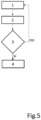
Fig. 5 shows an example of a flow diagram representative of the method object of the present invention. - The same reference numbers and letters in the figures designate equal or functionally equivalent parts.
- According to the present invention, the term "second element" does not imply the presence of a "first element", first, second, etc. They are used only to enhance the clarity of the description and should not be construed in a restrictive manner.
-
Fig.1 discloses a construction vehicle such as a wheel loader VHE equipped with an arm A including a first element A_1, substantially elongated, hinged to the vehicle chassis F and a second element A_2, such as a bucket or a fork, hinged to the first element. More specifically, a first end of the first element is connected to the chassis F of the vehicle, while a second end, opposite to the first, supports the second element. - It is clear that the first element can assume more angular positions with respect to the frame F.
- The hydraulic actuator A1 is arranged to control the angular position of the first element A_1 with respect to the vehicle chassis.
- The hydraulic actuator A2 is arranged to control the angular position of the second element A_2 with respect to the first element A_1.
- The hydraulic actuators A1, A2 are of the double action type, with two opposing chambers separated by a mobile septum integral with the stem of the respective actuator.
- An electro-hydraulic valve, not shown, controls the connection of one of these opposing chambers alternatively with the source of hydraulic oil or with the hydraulic oil collection tank.
- Generally, when one chamber is connected with the hydraulic oil source, its opposite chamber is connected with the collection tank.
- An electro-hydraulic valve, generally with an open centre, therefore takes care of the control of a respective actuator. The activation of the valve is instead controlled by a human/machine interface device, such as a joystick JK, shown in
Fig. 4 . - There may be various buttons on the joystick, the functionality of which may be fixed or programmable depending on the settings given by the operator via the
button panel 21 inFig. 2 or theinstrument panel 20 shown inFig. 3 . - The joystick includes a
wheel 26 or a lever that can assume three stable positions that allows you to make adjustments to some operational settings. Preferably, the joystick further comprises at least onebutton - According to the present invention, a first software module is responsible for monitoring the configurations assumed by the arm and the activation of the propulsion system and determining the current mission of the vehicle.
- Based on this recognition, it is checked whether the current mission coincides with a loading mission onto a truck.
- Evidently, a second software module can be provided configured to receive the current recognized mission as input and to access a look up table in which the automatic return functions correlated with the current mission are listed and a mapping of the buttons and levers/wheels of the joysticks that can be associated with a corresponding function when the same is enabled.
- More preferably, a VCU processing unit is configured to implement the first and second software modules and to control the
instrument panel 20 in particular to reproduce messages via therespective display 22. - In particular, the processing unit is configured to check whether the function(s) are enabled or not.
- In particular, when the vehicle carries out a truck loading mission repetitively for at least a predetermined time interval, then it is verified that the transfer or sharing of the forward/neutral/reverse gear selection function from/between a man/machine interface command arranged on the dashboard and a wheel/lever located on the joystick.
- Preferably, the enabling of an automatic return function among those described above is also verified.
- In particular, the processing unit is configured to check whether at least one of the functions is enabled, if the check is positive, i.e. the function being checked is enabled then nothing is suggested to the operator, otherwise, his enabling is suggested.
- Evidently, this verification can be performed in succession or in parallel on all the transfer and/or return functions described above.
- Using one of the buttons available to him on the dashboard, the operator can set the automatic enabling of the functions, handing control over to the VCU processing unit.
- In this case, no suggestion is given, but the automatic return functions are automatically enabled and this enabling is notified if necessary.
- Advantageously, the operator is given the possibility of deciding whether permitting the vehicle automatically deciding which functions to enable and parameters to set or to maintain the control of the enabling of the functions, so that the vehicle limits itself to making suggestions via the instrument panel.
- Among the parameters that can be set, in the case of loading onto a truck, the displacement of the hydraulic pump and/or of the hydraulic motor of the hydrostat that makes up the vehicle transmission can be controlled.
- Advantageously, without intervening on the vehicle speed set by the operator, the transmission ratio can be modified to more easily cope with resistance torque peaks, especially when inserting the bucket into a pile of material to be moved.
- With reference to
figure 5 , an exemplary flow diagram of the present invention is shown. The dotted blocks are optional: - Step 1: Observation of frequency and duration of each operational configuration of the arm and activation of the propulsion system;
- Step 2: determination of the vehicle current mission;
- Step 3: check whether said vehicle mission coincides with a truck loading mission and if so
- Step 4: suggestion or setting of the association of the forward/neutral/reverse gear selection with a button or joystick lever/wheel, otherwise it starts from the beginning. After the association, it is also possible to enable the automatic return function. This enabling can be automatic or managed by the operator. After that, the system returns to observe the operation of the arm and transmission and determine the current mission.
- It is clear that the method can be performed continuously to check whether the mission varies over time and, if necessary, to suggest disabling of the previously suggested functions. Therefore, to generalize the flow diagram, there may be a further step, immediately after
Step 1, in which the currently enabled function(s) is acquired and immediately afterstep 3 there may be a step to check whether the automatic and possibly the relevant parameters currently active are related to the truck loading mission, if so the cycle starts again fromstep 1, while if not it continues withsteps 4 and following. This further check allows to avoid sending suggestions to the operator for functions already previously activated. According to a preferred variant of the invention, the first software module is configured to detect the vehicle mission as a function of the frequency balance of the arm configurations and the respective time durations and as a function of the transmission enablement and the frequency of the values discrete vehicle speeds and respective durations. A position sensor is associated with each hydraulic actuator, therefore, it is immediate to acquire the operating configurations of the arm over time and analyze the frequency in discrete domains. - To make the solution easily implementable, the domains are segmented in such a way that the mutual positions of the elements composing the arm, which fall within a segment, are assumed to be approximately in the middle of the same segment. For further details, see the applicant's
European patent application n.21217267 - It is worth highlighting that suggestions can be given to the operator not only through messages that appear on the instrument panel or by the flashing of a light associated with an automatic function enable button, but also through voice messages.
- Likewise, the operator can confirm the enabling of an automatic function vocally.
- Therefore, the processing unit can advantageously be equipped with a speech synthesis module, an acoustic speaker and/or a microphone to give suggestions to the operator or to receive orders given by the operator.
- The present invention may advantageously be implemented in a computer program comprising program code means for performing one or more steps of such method, when such program is executed on a computer. For this reason, the patent will also cover such computer program and computer readable medium comprising a recorded message, such computer readable medium comprising program code means for carrying out one or more steps of such method, when such program is run on a computer.
- Many changes, modifications, variations and other uses and applications of the subject invention will be apparent to those skilled in the art after considering the accompanying description and drawings, which describe preferred embodiments thereof as described in the accompanying claims.
- The features disclosed in the background of the prior art are introduced only to better understand the invention and not as a statement about the existence of the prior art. Furthermore, said characteristics define the context of the present invention, therefore such characteristics will be considered in common with the detailed description.
- Further implementation details will not be described, as the person skilled in the art is able to implement the invention starting from the teaching of the above description.
Claims (7)
- Method computer-operated for supporting completion of a mission of work or agricultural vehicle, wherein the vehicle is equipped with- an articulated arm (A) connected to a chassis (F) of the vehicle such as to assume a plurality of operational configurations,- a joystick (JK) to control the articulated arm, where the joystick is equipped with a lever or a wheel (26),- a propulsion system that allows the vehicle to be moved with respect to a support surface,- a human/machine interface device, different from said joystick, associated with a vehicle dashboard to select forward, neutral or reverse gear,the method including in cyclic succession:- (Step 1) Observation, for a predetermined time interval, of a frequency and duration of each operational configuration and activation of the propulsion system,- (Step 2) Determining a current mission of the vehicle,- (Step 3) check whether said vehicle mission coincides with a truck loading mission, and if so then- (Step 4) suggestion or enabling of the association of the forward/neutral/reverse gear selection functionality with said lever or wheel (26) of the joystick.
- The method of claim 1, wherein said suggestion or enabling step also includes suggestion or enabling an automatic return function of the articulated arm, wherein the automatic return function comprises a procedure of moving the arm from any configuration to a pre-stored configuration.
- The method according to claim 2, wherein said enabling step of the automatic return function comprises the procedure of configuring a button (23, 24, 25) of the joystick to activate said automatic return function.
- Method according to any one of claims 1 - 3, wherein said enabling step also includes the setting of at least one operating parameter of an actuator of said articulated arm.
- A computer program comprising computer program code means adapted to perform all steps of claims 1 - 4, when said program is executed on a elaborating unit of a work or agricultural vehicle.
- A computer readable medium having stored the program of claim 5.
- Work or agricultural vehicle (VEH) comprising an articulated arm (A) connected to a chassis (F) of the vehicle such as to assume a plurality of operating configurations, a joystick (JK) to control the articulated arm, in which the joystick is equipped with a lever or a wheel (26), a propulsion system that allows movement of the vehicle with respect to a support surface, a man/machine interface device, different from said joystick, associated with a vehicle dashboard for perform the selection of forward, neutral or reverse gear, a processing unit (VCU) configured to observe, for a predetermined time interval, a frequency and time duration of each operational configuration, and a frequency and duration of system activation of propulsion and consequently to determine a current mission of the vehicle and to verify whether said mission of the vehicle coincides with a loading mission on a truck, and if so to suggest or enable an association of the forward/neutral/reverse gear selection functionality with the lever or wheel (26) of the joystick.
Applications Claiming Priority (1)
| Application Number | Priority Date | Filing Date | Title |
|---|---|---|---|
| IT102023000027705A IT202300027705A1 (en) | 2023-12-21 | 2023-12-21 | METHOD OF SUPPORT FOR THE COMPLETION OF A MISSION OF AN AGRICULTURAL OR WORK VEHICLE AND A CONTROL UNIT IMPLEMENTING THE METHOD |
Publications (1)
| Publication Number | Publication Date |
|---|---|
| EP4575100A1 true EP4575100A1 (en) | 2025-06-25 |
Family
ID=89983445
Family Applications (1)
| Application Number | Title | Priority Date | Filing Date |
|---|---|---|---|
| EP24221295.9A Pending EP4575100A1 (en) | 2023-12-21 | 2024-12-18 | Method for supporting completion of a mission of an agricultural or work vehicle and a control unit implementing the method |
Country Status (2)
| Country | Link |
|---|---|
| EP (1) | EP4575100A1 (en) |
| IT (1) | IT202300027705A1 (en) |
Citations (2)
| Publication number | Priority date | Publication date | Assignee | Title |
|---|---|---|---|---|
| US20020073833A1 (en) | 2000-12-18 | 2002-06-20 | Coombs Edwin G. | Return to dig system |
| US20220215225A1 (en) * | 2021-01-07 | 2022-07-07 | Cnh Industrial America Llc | Method For Detecting A Work Or Agricultural Vehicle Mission Though A Neural Network And Control Unit Implementing The Method |
-
2023
- 2023-12-21 IT IT102023000027705A patent/IT202300027705A1/en unknown
-
2024
- 2024-12-18 EP EP24221295.9A patent/EP4575100A1/en active Pending
Patent Citations (2)
| Publication number | Priority date | Publication date | Assignee | Title |
|---|---|---|---|---|
| US20020073833A1 (en) | 2000-12-18 | 2002-06-20 | Coombs Edwin G. | Return to dig system |
| US20220215225A1 (en) * | 2021-01-07 | 2022-07-07 | Cnh Industrial America Llc | Method For Detecting A Work Or Agricultural Vehicle Mission Though A Neural Network And Control Unit Implementing The Method |
Also Published As
| Publication number | Publication date |
|---|---|
| IT202300027705A1 (en) | 2025-06-21 |
Similar Documents
| Publication | Publication Date | Title |
|---|---|---|
| EP4026954B1 (en) | Method for detecting a work or agricultural vehicle mission through a neural network and control unit implementing the method | |
| US7738979B2 (en) | Work tool notification and user-selectable machine control configuration | |
| US6371214B1 (en) | Methods for automating work machine functions | |
| US7072745B2 (en) | Refuse vehicle control system and method | |
| US9345204B2 (en) | Control of a boom construction and a tool articulated thereto | |
| EP2984532B1 (en) | Vehicle and operator guidance by pattern recognition | |
| US8843282B2 (en) | Machine, control system and method for hovering an implement | |
| US6757994B1 (en) | Automatic tool orientation control for backhoe with extendable dipperstick | |
| JP2013515885A (en) | System and method for controlling instruments to maximize machine productivity and maintain final slope | |
| CN104053912A (en) | Work implement control system | |
| EP2939529B1 (en) | A method and a system for controlling the crane of a forest machine | |
| GB2518236A (en) | Training apparatus | |
| US9388551B2 (en) | Shift logic for ground ripping machine | |
| EP4575099A1 (en) | Method for supporting completion of a mission of an agricultural or work vehicle and a control unit implementing the method | |
| EP4575106A1 (en) | Method for supporting an execution of a mission of an agricultural or work vehicle and a control unit implementing the method | |
| EP2939530B1 (en) | A method and a system for controling the crane of a forwarder | |
| EP4575096A1 (en) | Method for supporting an execution of a mission of an agricultural or work vehicle and a control unit implementing the method | |
| EP4124760B1 (en) | Electro-hydraulic actuation circuit of a hydraulic actuator for an electrified work vehicle and corresponding method | |
| EP4737648A1 (en) | Method of supporting the execution of a mission of an agricultural or work vehicle and a control unit implementing the method | |
| IT202300027705A1 (en) | METHOD OF SUPPORT FOR THE COMPLETION OF A MISSION OF AN AGRICULTURAL OR WORK VEHICLE AND A CONTROL UNIT IMPLEMENTING THE METHOD | |
| CN113818513A (en) | Remote manual and autonomous work machine control | |
| EP3995633B1 (en) | System and method for work state estimation and control of self-propelled work vehicles | |
| JP6728101B2 (en) | Work machine | |
| IT202300027756A1 (en) | METHOD OF SUPPORT FOR THE COMPLETION OF A MISSION OF AN AGRICULTURAL OR WORK VEHICLE AND A CONTROL UNIT IMPLEMENTING THE METHOD | |
| IT202300027957A1 (en) | METHOD OF SUPPORT FOR THE COMPLETION OF A MISSION OF AN AGRICULTURAL OR WORK VEHICLE AND A CONTROL UNIT IMPLEMENTING THE METHOD |
Legal Events
| Date | Code | Title | Description |
|---|---|---|---|
| PUAI | Public reference made under article 153(3) epc to a published international application that has entered the european phase |
Free format text: ORIGINAL CODE: 0009012 |
|
| STAA | Information on the status of an ep patent application or granted ep patent |
Free format text: STATUS: THE APPLICATION HAS BEEN PUBLISHED |
|
| AK | Designated contracting states |
Kind code of ref document: A1 Designated state(s): AL AT BE BG CH CY CZ DE DK EE ES FI FR GB GR HR HU IE IS IT LI LT LU LV MC ME MK MT NL NO PL PT RO RS SE SI SK SM TR |
|
| STAA | Information on the status of an ep patent application or granted ep patent |
Free format text: STATUS: REQUEST FOR EXAMINATION WAS MADE |
|
| 17P | Request for examination filed |
Effective date: 20260102 |
|
| GRAP | Despatch of communication of intention to grant a patent |
Free format text: ORIGINAL CODE: EPIDOSNIGR1 |
|
| STAA | Information on the status of an ep patent application or granted ep patent |
Free format text: STATUS: GRANT OF PATENT IS INTENDED |
|
| RIC1 | Information provided on ipc code assigned before grant |
Ipc: E02F 3/43 20060101AFI20260513BHEP Ipc: E02F 9/20 20060101ALI20260513BHEP Ipc: E02F 9/22 20060101ALI20260513BHEP Ipc: E02F 9/26 20060101ALI20260513BHEP |
|
| INTG | Intention to grant announced |
Effective date: 20260522 |