EP4575080A1 - Disperger with a dilution system - Google Patents
Disperger with a dilution system Download PDFInfo
- Publication number
- EP4575080A1 EP4575080A1 EP24200676.5A EP24200676A EP4575080A1 EP 4575080 A1 EP4575080 A1 EP 4575080A1 EP 24200676 A EP24200676 A EP 24200676A EP 4575080 A1 EP4575080 A1 EP 4575080A1
- Authority
- EP
- European Patent Office
- Prior art keywords
- disperger
- dilution
- pulp
- pipe connection
- inlet pipe
- Prior art date
- Legal status (The legal status is an assumption and is not a legal conclusion. Google has not performed a legal analysis and makes no representation as to the accuracy of the status listed.)
- Pending
Links
Images

Classifications
-
- D—TEXTILES; PAPER
- D21—PAPER-MAKING; PRODUCTION OF CELLULOSE
- D21D—TREATMENT OF THE MATERIALS BEFORE PASSING TO THE PAPER-MAKING MACHINE
- D21D1/00—Methods of beating or refining; Beaters of the Hollander type
- D21D1/004—Methods of beating or refining including disperging or deflaking
-
- B—PERFORMING OPERATIONS; TRANSPORTING
- B01—PHYSICAL OR CHEMICAL PROCESSES OR APPARATUS IN GENERAL
- B01F—MIXING, e.g. DISSOLVING, EMULSIFYING OR DISPERSING
- B01F33/00—Other mixers; Mixing plants; Combinations of mixers
- B01F33/80—Mixing plants; Combinations of mixers
- B01F33/82—Combinations of dissimilar mixers
- B01F33/821—Combinations of dissimilar mixers with consecutive receptacles
- B01F33/8212—Combinations of dissimilar mixers with consecutive receptacles with moving and non-moving stirring devices
-
- B—PERFORMING OPERATIONS; TRANSPORTING
- B01—PHYSICAL OR CHEMICAL PROCESSES OR APPARATUS IN GENERAL
- B01F—MIXING, e.g. DISSOLVING, EMULSIFYING OR DISPERSING
- B01F35/00—Accessories for mixers; Auxiliary operations or auxiliary devices; Parts or details of general application
- B01F35/40—Mounting or supporting mixing devices or receptacles; Clamping or holding arrangements therefor
-
- B—PERFORMING OPERATIONS; TRANSPORTING
- B01—PHYSICAL OR CHEMICAL PROCESSES OR APPARATUS IN GENERAL
- B01F—MIXING, e.g. DISSOLVING, EMULSIFYING OR DISPERSING
- B01F35/00—Accessories for mixers; Auxiliary operations or auxiliary devices; Parts or details of general application
- B01F35/40—Mounting or supporting mixing devices or receptacles; Clamping or holding arrangements therefor
- B01F35/43—Supporting receptacles on frames or stands
-
- B—PERFORMING OPERATIONS; TRANSPORTING
- B01—PHYSICAL OR CHEMICAL PROCESSES OR APPARATUS IN GENERAL
- B01F—MIXING, e.g. DISSOLVING, EMULSIFYING OR DISPERSING
- B01F35/00—Accessories for mixers; Auxiliary operations or auxiliary devices; Parts or details of general application
- B01F35/50—Mixing receptacles
-
- B—PERFORMING OPERATIONS; TRANSPORTING
- B01—PHYSICAL OR CHEMICAL PROCESSES OR APPARATUS IN GENERAL
- B01F—MIXING, e.g. DISSOLVING, EMULSIFYING OR DISPERSING
- B01F35/00—Accessories for mixers; Auxiliary operations or auxiliary devices; Parts or details of general application
- B01F35/71—Feed mechanisms
- B01F35/717—Feed mechanisms characterised by the means for feeding the components to the mixer
-
- B—PERFORMING OPERATIONS; TRANSPORTING
- B01—PHYSICAL OR CHEMICAL PROCESSES OR APPARATUS IN GENERAL
- B01F—MIXING, e.g. DISSOLVING, EMULSIFYING OR DISPERSING
- B01F35/00—Accessories for mixers; Auxiliary operations or auxiliary devices; Parts or details of general application
- B01F35/71—Feed mechanisms
- B01F35/717—Feed mechanisms characterised by the means for feeding the components to the mixer
- B01F35/7179—Feed mechanisms characterised by the means for feeding the components to the mixer using sprayers, nozzles or jets
-
- D—TEXTILES; PAPER
- D21—PAPER-MAKING; PRODUCTION OF CELLULOSE
- D21D—TREATMENT OF THE MATERIALS BEFORE PASSING TO THE PAPER-MAKING MACHINE
- D21D1/00—Methods of beating or refining; Beaters of the Hollander type
- D21D1/004—Methods of beating or refining including disperging or deflaking
- D21D1/006—Disc mills
Definitions
- the present invention relates to dispergers to be used in connection with pulp and fiber web production. More especially the invention relates to a disperger with a dilution system according to the preamble part of the independent disperger claim.
- a typical production and treatment line comprises a forming section comprising a head box and a forming unit and a press section as well as a subsequent drying section and a reel-up.
- the fiber web production line can further comprise other devices and sections for finishing the fiber web, for example, a size press, a calender, a coating section, and typically at least one slitter-winder for forming customer rolls as well as a roll packaging apparatus.
- a treatment system of the fiber suspensions for example comprises a pulping section, a deashing system, a detrashing system, a coarse filtering section, a centrifugal cleaning section, a fractionation section, a fine filtering system, a fiber thickening system and fiber refining systems.
- dispersing by a disperger can be used. Dispersing of the pulp does not actually remove the contaminants nor cut or break the fibers but releases fibers from the contaminants and reduces particulate size of stickies.
- the pulp is defibred and/or treated to diminish negative effects of the contaminants to a quality and a runnability of the pulp or to facilitate a removal of the contaminants in process stages following the dispersing in the disperger.
- the dispersing contaminants attached to the fibers are detached and made smaller for removal of the is easier in the following treatment stages and/or for minimizing visibility of the contaminants in the fiber web products.
- dispersing sticky particles remaining in the pulp are broken up in order to prevent a formation of accumulations thereof, which may have negative effects on runnability in the fiber web production.
- a typical disperger comprises coaxial oppositely positioned disperger discs, which have opposite dispersing surfaces forming processing surfaces.
- the processing surfaces cause impacts to the pulp to be dispersed, whereby effects of these impacts together with effects of internal friction in the pulp detach the contaminant particles from the pulp and break them up into smaller pieces.
- dispersing improves pulp quality by reducing the particle size of undesirable contaminants affecting the downstream processes in recovered fiber systems and especially in demanding OCC (Old Corrugated Cardboard/Containers) processes, dispersion also improves fiber strength and machine runnability.
- Dispersion of recycled pulp, in particular OCC pulp is known to be conducted advantageously in consistency of 20-40%, which provides for best effect in view of removal of stickies and ink particles. This also provides that freeness of the pulp is not increased too much, as would occur if low consistency refining would be used, and thus, runnability properties of the pulp are better i.e. it is possible to use higher running speeds.
- the pulp with the consistency of 20-40% must be diluted to be suitable for the following treatment stages. Typically, the dilution is provided by feeding dilution water into the pulp in the disperger such, that desired consistency, for example 6 %, is achieved.
- the dilution can also be provided in a separate device after the dispersing in the disperger.
- the dilution water is typically fed into the disperger from its outer edge perpendicularly towards the to rotational axis of the disperger and the diluted pulp is removed from the disperger by pumping with a pump.
- the feed of the dilution water is provided from sides or from back of the disperger and a separate pump is provided to transfer the pulp to next stage or container.
- the known dilution systems of the dispergers are complicated and require additional equipment for removing the diluted pulp from the disperger.
- an object of the invention is to create a disperger with an improved dilution system, in particular in respect of its efficiency.
- the disperger with the dilution system comprises an inlet pipe connection for feeding pulp into the disperger, a dispersing system for dispersing pulp in the disperger and a dilution system for diluting the dispersed pulp
- the disperger comprises a housing, inside of which a dilution space of the dilution system is located, which dilution system comprises an outlet pipe connection for removing diluted pulp from the dilution system and at least one inlet pipe connection for dilution water, wherein at least one inlet pipe connection for dilution water is arranged tangentially at an outer edge of the housing and the tangential dilution water feed/-s from the tangentially located inlet pipe connection/-s is configured to provide an centrifugal force to the flow of the dispersed pulp and the dilution water in the dilution space and to provide along an inner surface of the housing of the dilution space a rotational-type flow of the dispersed pulp and the
- the flow of the dispersed pulp and the dilution water is configured to provide an increase in pressure at the outlet pipe connection and provide removal of the diluted pulp from the disperger by the centrifugal force.
- the outlet pipe connection is located on top or bottom part of the dilution system.
- the inlet pipe connection for feeding pulp into the disperger is located on top of the disperger.
- the disperger comprises a feeding screw for feeding pulp received from the inlet pipe connection to the dispersing system of the disperger.
- the feeding screw is arranged below the inlet pipe connection.
- the dispersing system comprises two coaxial oppositely positioned disperger discs, which have to each other opposite dispersing surfaces and at least one of the disperger discs is rotatable relative to the other.
- the dilution system is a separate constructional part located in connection with the disperger.
- At least one feed for the dilution water is arranged at the outer edge of the disperger tangentially.
- the tangential dilution water feed/-s increase/-s pressure in the outlet of the diluted pulp and provide removal of the diluted pulp from the disperger by the centrifugal force, thus, no separate pump is needed for removal of the diluted pulp from the disperger.
- the tangential feed /-s of the dilution water in the dilution part of the disperger accelerate the dispersed pulp into a rotational movement, which provides removal of the diluted pulp from the disperger by the centrifugal force.
- no separate pump is needed for removal of the diluted pulp from the disperger and saves in investment costs, space requirements, energy consumption and maintenance work is achieved.
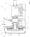
- FIGS 1-2 and 3A-3B is schematically shown an example of a disperger 10, which comprises a dispersing system 20 and a dilution system 30, which are located inside a housing 25.
- the housing 25 has a cylindrical form.
- the dilution system 30 comprises a dilution space 35 arranged inside the housing 25 and has a cylindrical form.
- the disperger 10 further comprises an inlet pipe connection 11 located on top of the disperger 10 for feeding pulp into the disperger 10.
- the disperger 10 advantageously also comprises a supply of steam 14 for pressurized steam arranged in connection with the inlet pipe connection 11 for pulp.
- the disperger 10 has a frame 16, inside of which a feeding screw 13 arranged below the inlet pipe connection 11 for feeding the pulp received from the inlet pipe connection 11 to the dispersing system 20 of the disperger 10.
- a feeding screw 13 arranged below the inlet pipe connection 11 for feeding the pulp received from the inlet pipe connection 11 to the dispersing system 20 of the disperger 10.
- the disperger discs 21, 22 have to each other opposite dispersing surfaces forming processing surfaces. When the disperger discs 21, 22 are rotated relative to each other, the to each other opposite dispersing surfaces cause impacts to the pulp to be dispersed, whereby effects of these impacts together with effects of internal friction in the pulp detach the contaminant particles from the pulp and break them up into smaller pieces.
- the feeding screw 13 is mounted on a rotatable shaft 12, which also provides for the rotational movement of at least one of the disperger discs 21, 22 relative to the other.
- the rotatable shaft 12 is connected to a power transmission 15 providing the power for the rotational movement of the shaft 12.
- the dispersing system 20 and the dilution system 30 are arranged as parts of the disperger 10 and inside the same housing 25 but the dilution system 30 can also be arranged in connection with the disperger 10 and its dispersing system 20 as a from the disperger 10 and its dispersing system 20 separate part and has its own housing.
- the feeding of the pulp to the disperger discs 21, 22 is arranged by means of the inlet pipe connection 11 and the feeding screw 13 but also other feed arrangements, for example the feed can be arranged from other direction and/or instead the feeding screw 13 other feeding means can be used.
- the dilution system 30 of the disperger 10 can be seen in more detail.
- the dilution system 30 is arranged in process direction to follow the dispersing system 20 such that the dispersed pulp is diluted after the dispersion thereof.
- the dilution system 30 comprises the dilution space 35 arranged inside the housing 25, in which dilution space 35 the dispersed pulp is diluted.
- the dilution system 30 comprises an outlet pipe connection 31 for the diluted pulp and at least one inlet pipe connection 32; 33, in this example two inlet pipe connections 32, 33 located at opposite sides of the dilution space 35 tangentially in respect of the inner surface of the housing 25 of the dilution space 35, i.e.
- the outlet pipe connection 31 is in the example of the figures located on top part of the dilution system 30 but the outlet pipe connection can also be located at any suitable position around the dilution system 30, advantageously the outlet pipe connection is located at bottom part of the dilution system 30, in which case also gravity helps the removal of the diluted pulp.
- At least one inlet pipe connection 32; 33 for the dilution water, in this example the two inlet pipe connections 32, 33, for feeding the dilution water is/are arranged tangentially at the outer edge of the housing 25 of the dilution system 30 of the disperger 10.
- the tangential dilution water feed/-s from the tangentially located inlet pipe connection/-s 32, 33 causing along the inner surface of the dilution space 35 progressing rotational-type flow F of the dispersed pulp and the dilution water and also increase/-s pressure in the outlet 31 of the diluted pulp and provide removal of the diluted pulp from the disperger 10 by the centrifugal force.
Landscapes
- Chemical & Material Sciences (AREA)
- Chemical Kinetics & Catalysis (AREA)
- Paper (AREA)
Abstract
The invention relates to a disperger with a dilution system, which disperger (10) comprises an inlet pipe connection (11) for feeding pulp into the disperger (10), a dispersing system (20) for dispersing pulp in the disperger (10) and a dilution system (30) for diluting the dispersed pulp, which disperger (10) comprises a housing (25), inside of which a dilution space (35) of the dilution system (30) is located, which dilution system (30) comprises an outlet pipe connection (31) for removing diluted pulp from the dilution system (30) and at least one inlet pipe connection (32; 33) for dilution water. At least one inlet pipe connection (32; 33) for dilution water is arranged tangentially at an outer edge of the housing (25) and the tangential dilution water feed/-s from the tangentially located inlet pipe connection/-s (32, 33) is configured to provide an centrifugal force to the flow of the dispersed pulp and the dilution water in the dilution space (35) and to provide along an inner surface of the housing (25) if the dilution space (35) a rotational-type flow (F) of the dispersed pulp and the dilution water towards the outlet pipe connection (31).
Description
- The present invention relates to dispergers to be used in connection with pulp and fiber web production. More especially the invention relates to a disperger with a dilution system according to the preamble part of the independent disperger claim.
- As known from the prior art in fiber web production lines, especially in paper and board production lines, the fiber web is produced and treated in an assembly formed by a number of apparatuses arranged consecutively in a process line. A typical production and treatment line comprises a forming section comprising a head box and a forming unit and a press section as well as a subsequent drying section and a reel-up. The fiber web production line can further comprise other devices and sections for finishing the fiber web, for example, a size press, a calender, a coating section, and typically at least one slitter-winder for forming customer rolls as well as a roll packaging apparatus.
- Before the head box fiber suspensions comprising recycled and/or virgin fibers are treated to be fed into the head box to be used to produce the fiber webs. A treatment system of the fiber suspensions for example comprises a pulping section, a deashing system, a detrashing system, a coarse filtering section, a centrifugal cleaning section, a fractionation section, a fine filtering system, a fiber thickening system and fiber refining systems.
- Producing of fiber webs from recycled fibers received from recycling of wastepaper and packaging material has increased in the present days, due to environmental, energy saving and sustainability reasons. In the treatment systems of the fiber suspensions for production of fiber webs several processes are used to remove ink, tone, plastics and stickies etc. which are present in the recycled material. Thus, when fiber web products are manufactured from pulp containing recycled fibers, there is the need to process different contaminants in the pulp before the fiber suspension is entered into the fiber web production process in order to reduce effects of the contaminants to the pulp as well as to a fiber web forming in the head box and in the forming section of the fiber web production line. These contaminants may include for example printing inks and surface coating agents, such as different stickies, waxes, adhesives and pastes.
- In connection with removing the contaminants from the fiber suspensions dispersing by a disperger can be used. Dispersing of the pulp does not actually remove the contaminants nor cut or break the fibers but releases fibers from the contaminants and reduces particulate size of stickies. In the disperger the pulp is defibred and/or treated to diminish negative effects of the contaminants to a quality and a runnability of the pulp or to facilitate a removal of the contaminants in process stages following the dispersing in the disperger. In the dispersing contaminants attached to the fibers are detached and made smaller for removal of the is easier in the following treatment stages and/or for minimizing visibility of the contaminants in the fiber web products. In the dispersing sticky particles remaining in the pulp are broken up in order to prevent a formation of accumulations thereof, which may have negative effects on runnability in the fiber web production.
- A typical disperger comprises coaxial oppositely positioned disperger discs, which have opposite dispersing surfaces forming processing surfaces. When the disperger discs are rotated relative to each other, the processing surfaces cause impacts to the pulp to be dispersed, whereby effects of these impacts together with effects of internal friction in the pulp detach the contaminant particles from the pulp and break them up into smaller pieces. Thus, dispersing improves pulp quality by reducing the particle size of undesirable contaminants affecting the downstream processes in recovered fiber systems and especially in demanding OCC (Old Corrugated Cardboard/Containers) processes, dispersion also improves fiber strength and machine runnability.
- Dispersion of recycled pulp, in particular OCC pulp, is known to be conducted advantageously in consistency of 20-40%, which provides for best effect in view of removal of stickies and ink particles. This also provides that freeness of the pulp is not increased too much, as would occur if low consistency refining would be used, and thus, runnability properties of the pulp are better i.e. it is possible to use higher running speeds. After dispersing in the disperger the pulp with the consistency of 20-40%, must be diluted to be suitable for the following treatment stages. Typically, the dilution is provided by feeding dilution water into the pulp in the disperger such, that desired consistency, for example 6 %, is achieved. The dilution can also be provided in a separate device after the dispersing in the disperger. In known dilution systems, the dilution water is typically fed into the disperger from its outer edge perpendicularly towards the to rotational axis of the disperger and the diluted pulp is removed from the disperger by pumping with a pump. Typically, thus in known dilution systems of the disperger the feed of the dilution water is provided from sides or from back of the disperger and a separate pump is provided to transfer the pulp to next stage or container. Thus, the known dilution systems of the dispergers are complicated and require additional equipment for removing the diluted pulp from the disperger.
- An object of the invention is to create a disperger with a dilution system, in which the disadvantages and problems of prior art are eliminated or at least minimized.
- In particular an object of the invention is to create a disperger with an improved dilution system, in particular in respect of its efficiency.
- In particular an object of the invention is to create a disperger with an improved dilution system, in particular with a simplified configuration, especially in view of the equipment needed in connection with removal of the diluted pulp.
- In order to achieve the above objects and those that will come apparent later the disperger with a dilution system according to the invention is mainly characterized by the features of the characterizing part of the independent disperger claim. Advantageous aspects and features of the invention are presented in the dependent claims.
- According to the invention the disperger with the dilution system comprises an inlet pipe connection for feeding pulp into the disperger, a dispersing system for dispersing pulp in the disperger and a dilution system for diluting the dispersed pulp, which disperger comprises a housing, inside of which a dilution space of the dilution system is located, which dilution system comprises an outlet pipe connection for removing diluted pulp from the dilution system and at least one inlet pipe connection for dilution water, wherein at least one inlet pipe connection for dilution water is arranged tangentially at an outer edge of the housing and the tangential dilution water feed/-s from the tangentially located inlet pipe connection/-s is configured to provide an centrifugal force to the flow of the dispersed pulp and the dilution water in the dilution space and to provide along an inner surface of the housing of the dilution space a rotational-type flow of the dispersed pulp and the dilution water towards the outlet pipe connection.
- In this description and in the claims by the terms "tangential," "tangentially" etc. is meant tangential direction in respect of inner surface of the housing of the dilution space, whereby dilution water flow substantially directly after infeed begins to follow the inner surface of the housing of the dilution space. Thus, the terms "tangential direction/location" etc. are used in the meaning of a direction/location deviating from the radial direction, i.e. an inclined direction in respect of a perpendicular direction. Furthermore, the deviation from the radial direction / perpendicular direction is advantageously greater than 45 degrees. Thus, f. ex. tangentially arranged inlet pipe connection for dilution water to the dilution system inside a housing having a substantially cylindrical form are arranged in a direction that deviates from the radial direction of the cylindrical form.
- According to an advantageous feature of the invention the flow of the dispersed pulp and the dilution water is configured to provide an increase in pressure at the outlet pipe connection and provide removal of the diluted pulp from the disperger by the centrifugal force.
- According to an advantageous feature of the invention the dilution system comprises at least two inlet pipe connections located at circumferential positions spaced apart around the dilution space tangentially at the outer edge of the housing of the dilution space.
- According to an advantageous feature of the invention the outlet pipe connection is located on top or bottom part of the dilution system.
- According to an advantageous feature of the invention the inlet pipe connection for feeding pulp into the disperger is located on top of the disperger.
- According to an advantageous feature of the invention the disperger comprises a supply of steam for pressurized steam arranged in connection with the inlet pipe connection for pulp.
- According to an advantageous feature of the invention the disperger comprises a feeding screw for feeding pulp received from the inlet pipe connection to the dispersing system of the disperger.
- According to an advantageous feature of the invention the feeding screw is arranged below the inlet pipe connection.
- According to an advantageous feature of the invention the dispersing system comprises two coaxial oppositely positioned disperger discs, which have to each other opposite dispersing surfaces and at least one of the disperger discs is rotatable relative to the other.
- According to an advantageous feature of the invention the dilution system is located inside the same housing with the dispersing system.
- According to an advantageous feature of the invention the dilution system is a separate constructional part located in connection with the disperger.
- According to an advantageous aspect of the invention in the disperger with the dilution system, at least one feed for the dilution water is arranged at the outer edge of the disperger tangentially. The tangential dilution water feed/-s increase/-s pressure in the outlet of the diluted pulp and provide removal of the diluted pulp from the disperger by the centrifugal force, thus, no separate pump is needed for removal of the diluted pulp from the disperger.
- According to an advantageous aspect of the invention in the disperger with the dilution system, to the pulp feed of the disperger is combined a supply of steam for pressurized steam, which provides for improving the dispersing and the dilution.
- By the invention and its advantageous features several advantages are achieved: The tangential feed /-s of the dilution water in the dilution part of the disperger accelerate the dispersed pulp into a rotational movement, which provides removal of the diluted pulp from the disperger by the centrifugal force. Thus, no separate pump is needed for removal of the diluted pulp from the disperger and saves in investment costs, space requirements, energy consumption and maintenance work is achieved.
- Aspects of the invention, however, together with additional objects and advantages thereof, will be best understood from the following description of some example embodiments when read in connection with the accompanying drawings and in the following the invention is described in more detail referring to the accompanying drawing, in which
- In
figure 1 is schematically shown an example of a disperger with a dilution system according to an advantageous example of the invention at a longitudinal partially cut side view. - In
figure 2 is schematically shown the example offigure 1 as an end view. - In
figures 3A - 3B is schematically shown partial longitudinal side views both sides of the example of thefigures 1-2 . - During the course of this description like numbers and signs will be used to identify like elements according to the different views which illustrate the invention. Repetition of some reference signs may have been omitted in the figures for clarity reasons.
- In
figures 1-2 and3A-3B is schematically shown an example of adisperger 10, which comprises adispersing system 20 and adilution system 30, which are located inside ahousing 25. Thehousing 25 has a cylindrical form. Thedilution system 30 comprises adilution space 35 arranged inside thehousing 25 and has a cylindrical form. Thedisperger 10 further comprises aninlet pipe connection 11 located on top of thedisperger 10 for feeding pulp into thedisperger 10. Thedisperger 10 advantageously also comprises a supply ofsteam 14 for pressurized steam arranged in connection with theinlet pipe connection 11 for pulp. Thedisperger 10 has aframe 16, inside of which afeeding screw 13 arranged below theinlet pipe connection 11 for feeding the pulp received from theinlet pipe connection 11 to the dispersingsystem 20 of thedisperger 10. In the dispersingsystem 20 two coaxial oppositely positioned disperger discs 21, 22 are located. The disperger discs 21, 22 have to each other opposite dispersing surfaces forming processing surfaces. When the disperger discs 21, 22 are rotated relative to each other, the to each other opposite dispersing surfaces cause impacts to the pulp to be dispersed, whereby effects of these impacts together with effects of internal friction in the pulp detach the contaminant particles from the pulp and break them up into smaller pieces. The feedingscrew 13 is mounted on arotatable shaft 12, which also provides for the rotational movement of at least one of the disperger discs 21, 22 relative to the other. Therotatable shaft 12 is connected to apower transmission 15 providing the power for the rotational movement of theshaft 12. In this example the dispersingsystem 20 and thedilution system 30 are arranged as parts of thedisperger 10 and inside thesame housing 25 but thedilution system 30 can also be arranged in connection with thedisperger 10 and itsdispersing system 20 as a from thedisperger 10 and itsdispersing system 20 separate part and has its own housing. Further, in this example the feeding of the pulp to the disperger discs 21, 22 is arranged by means of theinlet pipe connection 11 and the feedingscrew 13 but also other feed arrangements, for example the feed can be arranged from other direction and/or instead the feedingscrew 13 other feeding means can be used. - In the
figures 2 and 3A-3D thedilution system 30 of thedisperger 10 can be seen in more detail. Thedilution system 30 is arranged in process direction to follow the dispersingsystem 20 such that the dispersed pulp is diluted after the dispersion thereof. Thedilution system 30 comprises thedilution space 35 arranged inside thehousing 25, in whichdilution space 35 the dispersed pulp is diluted. Thedilution system 30 comprises anoutlet pipe connection 31 for the diluted pulp and at least oneinlet pipe connection 32; 33, in this example twoinlet pipe connections dilution space 35 tangentially in respect of the inner surface of thehousing 25 of thedilution space 35, i.e. in a direction deviating, advantageously at least 45 degrees, from the radial direction of thedilution space 35 inside thecylindrical housing 25, i.e. inclined in respect of the perpendicular direction of the outer surface, at the outer edge of thehousing 25 of thedilution space 35, for the dilution water for feeding the dilution water into thedilution space 35 containing the dispersed pulp. Theoutlet pipe connection 31 is in the example of the figures located on top part of thedilution system 30 but the outlet pipe connection can also be located at any suitable position around thedilution system 30, advantageously the outlet pipe connection is located at bottom part of thedilution system 30, in which case also gravity helps the removal of the diluted pulp. In thedisperger 10, in thedilution system 30 at least oneinlet pipe connection 32; 33 for the dilution water, in this example the twoinlet pipe connections housing 25 of thedilution system 30 of thedisperger 10. The tangential dilution water feed/-s from the tangentially located inlet pipe connection/-s dilution space 35 progressing rotational-type flow F of the dispersed pulp and the dilution water and also increase/-s pressure in theoutlet 31 of the diluted pulp and provide removal of the diluted pulp from thedisperger 10 by the centrifugal force. - In the description in the foregoing, although some functions have been described with reference to certain features, those functions may be performable by other features whether described or not. Although features have been described with reference to certain embodiments or examples, those features may also be present in other embodiments or examples whether described or not. Above the invention has been described by referring to some advantageous examples only to which the invention is not to be narrowly limited. Many modifications and alterations are possible within the invention as defined in the following claims.
- Reference signs used in the drawing:
- 10 disperger
- 11 inlet pipe connection of pulp
- 12 shaft
- 13 feeding screw
- 14 supply of steam
- 15 power transmission
- 16 frame
- 20 dispersing system
- 21, 22 dispersing disc
- 25 housing
- 30 dilution system
- 31 outlet
- 32, 33 inlet pipe connection of dilution water
- 35 dilution space
- F flow
Claims (12)
- Disperger with a dilution system, which disperger (10) comprises an inlet pipe connection (11) for feeding pulp into the disperger (10), a dispersing system (20) for dispersing pulp in the disperger (10) and a dilution system (30) for diluting the dispersed pulp, which disperger (10) comprises a housing (25), inside of which a dilution space (35) of the dilution system (30) is located, which dilution system (30) comprises an outlet pipe connection (31) for removing diluted pulp from the dilution system (30) and at least one inlet pipe connection (32; 33) for dilution water, characterized in that at least one inlet pipe connection (32; 33) for dilution water is arranged tangentially at an outer edge of the housing (25) and that the tangential dilution water feed/-s from the tangentially located inlet pipe connection/-s (32, 33) is configured to provide an centrifugal force to the flow of the dispersed pulp and the dilution water in the dilution space (35) and to provide along an inner surface of the housing (25) of the dilution space (35) a rotational-type flow (F) of the dispersed pulp and the dilution water towards the outlet pipe connection (31).
- Disperger with a dilution system according to claim 1, characterized in that the flow (F) of the dispersed pulp and the dilution water is configured to provide an increase in pressure at the outlet pipe connection (31) and provide removal of the diluted pulp from the disperger (10) by the centrifugal force.
- Disperger with a dilution system according to claim 1 or 2, characterized in that the dilution system (30) comprises at least two inlet pipe connections (32, 33) located at circumferential positions spaced apart around the dilution space (35) tangentially at the outer edge of the housing (25) of the dilution space (35).
- Disperger with a dilution system according to any of claims 1-3, characterized in that the outlet pipe connection (31) is located on top part of the dilution system (30).
- Disperger with a dilution system according to any of claims 1-3, characterized in that the outlet pipe connection (31) is located on bottom part of the dilution system (30).
- Disperger with a dilution system according to any of claims 1-5, characterized in that the inlet pipe connection (11) for feeding pulp into the disperger (10) is located on top of the disperger (10).
- Disperger with a dilution system according to any of claims 1-6, characterized in that the disperger (10) comprises a supply of steam (14) for pressurized steam arranged in connection with the inlet pipe connection (11) for pulp.
- Disperger with a dilution system according to any of claims 1-7, characterized in that the disperger (10) comprises a feeding screw (13) for feeding pulp received from the inlet pipe connection (11) to the dispersing system (20) of the disperger (10).
- Disperger with a dilution system according to claim 8, characterized in that the feeding screw (13) is arranged below the inlet pipe connection (11).
- Disperger with a dilution system according to any of claims 1-9, characterized in that the dispersing system (20) comprises two coaxial oppositely positioned disperger discs (21, 22), which have to each other opposite dispersing surfaces and that at least one of the disperger discs (21, 22) is rotatable relative to the other.
- Disperger with a dilution system according to any of claims 1-10, characterized in that the dilution system (30) is located inside the same housing (25) with the dispersing system (20).
- Disperger with a dilution system according to any of claims 1-10, characterized in that the dilution system (30) is a separate constructional part located in connection with the disperger (10).
Applications Claiming Priority (1)
| Application Number | Priority Date | Filing Date | Title |
|---|---|---|---|
| FI20236411A FI20236411A1 (en) | 2023-12-21 | 2023-12-21 | Disperger with a dilution system |
Publications (1)
| Publication Number | Publication Date |
|---|---|
| EP4575080A1 true EP4575080A1 (en) | 2025-06-25 |
Family
ID=92816344
Family Applications (1)
| Application Number | Title | Priority Date | Filing Date |
|---|---|---|---|
| EP24200676.5A Pending EP4575080A1 (en) | 2023-12-21 | 2024-09-17 | Disperger with a dilution system |
Country Status (3)
| Country | Link |
|---|---|
| EP (1) | EP4575080A1 (en) |
| CN (1) | CN120189866A (en) |
| FI (1) | FI20236411A1 (en) |
Citations (2)
| Publication number | Priority date | Publication date | Assignee | Title |
|---|---|---|---|---|
| GB997947A (en) * | 1960-07-14 | 1965-07-14 | Escher Wyss Gmbh | Improvements in or relating to processes and installations for treating fibrous material |
| US11795614B2 (en) * | 2019-06-20 | 2023-10-24 | Cellwood Machinery Ab | Apparatus and method for dispersing or refining of organic material, such as cellulose fiber and organic waste |
Family Cites Families (4)
| Publication number | Priority date | Publication date | Assignee | Title |
|---|---|---|---|---|
| SE429874B (en) * | 1982-02-16 | 1983-10-03 | Sunds Defibrator | SET AND DEVICE FOR MANUFACTURING FIBER MASS AND LIGNOCELLULOSALLY MATERIAL |
| DK171513B1 (en) * | 1988-08-30 | 1996-12-16 | Cellwood Machinery Ab | Process for treating and disperser for the comminuting of wood pulp, especially containing waste paper |
| FI10583U1 (en) * | 2014-05-16 | 2014-08-22 | Valmet Technologies Inc | The disperser |
| CN111321621B (en) * | 2020-04-22 | 2021-12-10 | 郑州磊展科技造纸机械有限公司 | Ultrahigh-concentration heat dispersion system for recycling pulp fibers |
-
2023
- 2023-12-21 FI FI20236411A patent/FI20236411A1/en unknown
-
2024
- 2024-09-17 EP EP24200676.5A patent/EP4575080A1/en active Pending
- 2024-12-11 CN CN202411817773.9A patent/CN120189866A/en active Pending
Patent Citations (2)
| Publication number | Priority date | Publication date | Assignee | Title |
|---|---|---|---|---|
| GB997947A (en) * | 1960-07-14 | 1965-07-14 | Escher Wyss Gmbh | Improvements in or relating to processes and installations for treating fibrous material |
| US11795614B2 (en) * | 2019-06-20 | 2023-10-24 | Cellwood Machinery Ab | Apparatus and method for dispersing or refining of organic material, such as cellulose fiber and organic waste |
Also Published As
| Publication number | Publication date |
|---|---|
| FI20236411A1 (en) | 2025-06-22 |
| CN120189866A (en) | 2025-06-24 |
Similar Documents
| Publication | Publication Date | Title |
|---|---|---|
| WO1999054045A1 (en) | Method and apparatus for processing pulp stock derived from a pulp or paper mill | |
| US5762756A (en) | Methods and apparatus for pulping and deinking | |
| EP4575080A1 (en) | Disperger with a dilution system | |
| US6053439A (en) | Reducing wax content and enhancing quality of recycled pulp from OCC and waste paper | |
| US6576088B2 (en) | Process for preparing dry broke | |
| US20060186235A1 (en) | Method for refining paper or cellulose fibers in an aqueous suspension | |
| EP1076735B1 (en) | Method and apparatus for treatment of fiber suspension containing minerals, such as coated broke, in paper production | |
| US20020129909A1 (en) | Method of removing high density stickies from secondary papermaking fibers | |
| US9370779B2 (en) | Method and arrangement | |
| EP3260596B1 (en) | Deashing system and deashing method | |
| CN111501393B (en) | Screening apparatus | |
| EP4343056B1 (en) | Disperger | |
| FI131238B1 (en) | Drum of a drum pulper and a drum pulper | |
| EP4484641A2 (en) | Horizontal pulper | |
| CN113089356A (en) | Waste paper pulping system | |
| EP3663462B1 (en) | A screening device and a rotor | |
| EP4644605B1 (en) | Pulper rotor | |
| US11560672B2 (en) | Methods for deinking UV prints | |
| FI105699B (en) | Method and use for the treatment of pulp from paper or paper mills | |
| CA2421886C (en) | Method of removing high density stickies from secondary papermaking fibers | |
| CN113249998A (en) | Waste paper pulping system | |
| Huston | Manufacture of newsprint using recycled fibres | |
| McKinney | 3 Wastepaper preparation and contamination | |
| Carstens | Technology in fibre recovery |
Legal Events
| Date | Code | Title | Description |
|---|---|---|---|
| PUAI | Public reference made under article 153(3) epc to a published international application that has entered the european phase |
Free format text: ORIGINAL CODE: 0009012 |
|
| STAA | Information on the status of an ep patent application or granted ep patent |
Free format text: STATUS: THE APPLICATION HAS BEEN PUBLISHED |
|
| AK | Designated contracting states |
Kind code of ref document: A1 Designated state(s): AL AT BE BG CH CY CZ DE DK EE ES FI FR GB GR HR HU IE IS IT LI LT LU LV MC ME MK MT NL NO PL PT RO RS SE SI SK SM TR |
|
| STAA | Information on the status of an ep patent application or granted ep patent |
Free format text: STATUS: THE APPLICATION IS DEEMED TO BE WITHDRAWN |