EP4575076A1 - Laundry drying device comprising a fluid diffuser arranged above an evaporator in the drying air channel - Google Patents
Laundry drying device comprising a fluid diffuser arranged above an evaporator in the drying air channel Download PDFInfo
- Publication number
- EP4575076A1 EP4575076A1 EP23218517.3A EP23218517A EP4575076A1 EP 4575076 A1 EP4575076 A1 EP 4575076A1 EP 23218517 A EP23218517 A EP 23218517A EP 4575076 A1 EP4575076 A1 EP 4575076A1
- Authority
- EP
- European Patent Office
- Prior art keywords
- flow channel
- height
- evaporator
- air
- channel
- Prior art date
- Legal status (The legal status is an assumption and is not a legal conclusion. Google has not performed a legal analysis and makes no representation as to the accuracy of the status listed.)
- Pending
Links
Images


Classifications
-
- D—TEXTILES; PAPER
- D06—TREATMENT OF TEXTILES OR THE LIKE; LAUNDERING; FLEXIBLE MATERIALS NOT OTHERWISE PROVIDED FOR
- D06F—LAUNDERING, DRYING, IRONING, PRESSING OR FOLDING TEXTILE ARTICLES
- D06F58/00—Domestic laundry dryers
- D06F58/20—General details of domestic laundry dryers
- D06F58/24—Condensing arrangements
-
- D—TEXTILES; PAPER
- D06—TREATMENT OF TEXTILES OR THE LIKE; LAUNDERING; FLEXIBLE MATERIALS NOT OTHERWISE PROVIDED FOR
- D06F—LAUNDERING, DRYING, IRONING, PRESSING OR FOLDING TEXTILE ARTICLES
- D06F58/00—Domestic laundry dryers
- D06F58/20—General details of domestic laundry dryers
-
- D—TEXTILES; PAPER
- D06—TREATMENT OF TEXTILES OR THE LIKE; LAUNDERING; FLEXIBLE MATERIALS NOT OTHERWISE PROVIDED FOR
- D06F—LAUNDERING, DRYING, IRONING, PRESSING OR FOLDING TEXTILE ARTICLES
- D06F58/00—Domestic laundry dryers
- D06F58/02—Domestic laundry dryers having dryer drums rotating about a horizontal axis
- D06F58/04—Details
-
- D—TEXTILES; PAPER
- D06—TREATMENT OF TEXTILES OR THE LIKE; LAUNDERING; FLEXIBLE MATERIALS NOT OTHERWISE PROVIDED FOR
- D06F—LAUNDERING, DRYING, IRONING, PRESSING OR FOLDING TEXTILE ARTICLES
- D06F58/00—Domestic laundry dryers
- D06F58/20—General details of domestic laundry dryers
- D06F58/206—Heat pump arrangements
Definitions
- the present disclosure relates to a laundry device comprising a diffuser, in particular to a dryer or wash-dryer comprising a diffuser.
- wet laundry is introduced into a laundry drum.
- liquid content of the wet laundry has to be reduced, for example, by removing liquid from the laundry.
- an evaporator of a heat exchange mechanism is provided to reduce the humidity of air circulating in the drying process.
- impurities of the laundry such as fluff, can be accommodated in the circulating air and can accumulate on the evaporator, thereby reducing the efficiency of the heat exchange mechanism and the drying process of the laundry.
- the present disclosure relates to a laundry device, wherein the laundry device comprises a drying chamber for drying laundry and an air channel, wherein the air channel is connected with the drying chamber via an air inlet and an air outlet, wherein the air inlet is configured to feed air from the drying chamber into the air channel, wherein the air outlet is configured to feed the air from the air channel back into the drying chamber, wherein an evaporator is arranged downstream of the air inlet in the air channel, wherein the evaporator is configured to cool down the air supplied by the air inlet to condense water at the evaporator during cooling of the air, wherein impurities, in particular fluff, in the air are deposited at the evaporator, wherein the laundry device comprises a collection container arranged below the evaporator, wherein the collection container is configured to collect the condensed water of the evaporator, wherein the collection container is fluidly connected via a pumping line with at least one fluid diffuser, which is arranged above the evaporator,
- the pumped water can be distributed evenly along the second width of the flow channel at the elevation and can evenly flow over the elevation. Therefore, the impurities, in particular the fluff, can be flushed efficiently from the evaporator into the collection container.
- a control of the laundry device may be configured to switch a ventil of the pump-out line and activate the pump to pump water together with the impurities, in particular the fluff, out of the collection container through the pump-out line.
- the laundry device according to the present disclosure in particular refers to a laundry device which is adapted to dry laundry, in particular by thereby removing or at least significantly reducing the amount of water attached to the laundry.
- the laundry device according to the present disclosure is a dryer, which is adapted to dry laundry. More particular, the laundry device according to the present disclosure is a heatpump tumble dryer.
- a fan is arranged in the air channel, which is configured to feed the air from the air inlet into the air channel and out of the air outlet.
- the fan may be arranged in the air inlet.
- the evaporator is arranged in a heat cycle of a heat pump, wherein a cooling means is circulating in the heat cycle of the heat pump, which cooling means is configured to cool down the evaporator.
- the heat cycle may further comprise a condenser for heating air, a compressor for increasing the temperature and the pressure of the cooling means and an expansion valve for reducing the temperature and the pressure of the cooling means.
- the expansion valve may be arranged downstream of the condenser in the heat cycle.
- the evaporator may be arranged downstream of the expansion valve in the heat cycle.
- the compressor may be arranged downstream of the evaporator in the heat cycle.
- the condenser may be arranged downstream of the compressor in the heat cycle.
- the at least one fluid diffuser comprises a first fluid diffuser arranged above a section of the evaporator and a further first fluid diffuser arranged above a further section of the evaporator, wherein the first fluid diffuser is configured to feed the pumped water onto the section of the evaporator to flush the impurities, in particular the fluff, from the section of the evaporator into the collection container, wherein the further first fluid diffuser is configured to feed the pumped water onto the further section of the evaporator to flush the impurities, in particular the fluff, from the further section of the evaporator into the collection container, wherein a first valve is arranged in the pumping line, wherein the pumping line is connected to the first fluid diffuser in a first state of the first valve and wherein the pumping line is connected to the further first fluid diffuser in a second state of the first valve.
- the first valve may be controlled by a control of the laundry device in order to flush a different section of the evaporator.
- the at least one fluid diffuser comprises a first fluid diffuser arranged above the evaporator and configured to feed the pumped water onto the evaporator to flush the impurities, in particular the fluff, from the evaporator into the collection container, wherein a condenser is arranged in the air channel downstream of the evaporator, wherein the condenser is configured to heat the air cooled by the evaporator, wherein further impurities, in particular further fluff, of the air are deposited at the condenser, wherein the collection container is arranged below the evaporator and the condenser, wherein the at least one fluid diffuser comprises a second fluid diffuser arranged above the condenser and configured to feed the pumped water onto the condenser to flush the further impurities, in particular further fluff, from the condenser into the collection container.
- a valve may be controlled by a control of the laundry device in order to switch between flushing the condenser and flushing the evaporator.
- the condenser is arranged in a heat cycle of a heat pump, wherein a cooling means is circulating in the heat cycle of the heat pump, which cooling means is configured to heat the condenser.
- the heat cycle may further comprise a compressor for increasing the temperature and the pressure of the cooling means and an expansion valve for reducing the temperature and the pressure of the cooling means.
- the expansion valve may be arranged downstream of the condenser in the heat cycle.
- the evaporator may be arranged downstream of the expansion valve in the heat cycle.
- the compressor may be arranged downstream of the evaporator in the heat cycle.
- the condenser may be arranged downstream of the compressor in the heat cycle.
- the at least one fluid diffuser comprises a second fluid diffuser arranged above a section of the condenser and a further second fluid diffuser arranged above a further section of the condenser, wherein the second fluid diffuser is configured to feed the pumped water onto the section of the condenser to flush the impurities, in particular the fluff, from the section of the condenser into the collection container, wherein the further second fluid diffuser is configured to feed the pumped water onto the further section of the condenser to flush the impurities, in particular the fluff, from the further section of the condenser into the collection container, wherein a second valve is arranged in the pumping line, wherein the pumping line is connected to the second fluid diffuser in a first state of the second valve and wherein the pumping line is connected to the further second fluid diffuser in a second state of the second valve.
- the second valve may be controlled by a control of the laundry device in order to flush a different section of the condenser.
- the first width of the flow channel is smaller than the second width of the flow channel, in particular wherein a width of the flow channel is continuously increasing from the first width along the flow direction to the second width.
- the pumped water can efficiently flow in the flow channel from the first width to the second width along the flow direction.
- the flow channel has a third width at the inlet section between the two side walls of the flow channel, wherein the third width is smaller than the first width, in particular wherein a width of the flow channel is continuously increasing from the third width along the flow direction to the first width.
- the pumped water can efficiently flow in the flow channel from the third width to the first width along the flow direction.
- the flow channel has a first height at the inlet section between the bottom wall of the flow channel and a top wall of the flow channel, wherein the flow channel has a second height in the intermediate section of the flow channel upstream of the recess between the bottom wall of the flow channel and the top wall of the flow channel, wherein the second height of the flow channel is smaller than the first height of the flow channel, in particular wherein a height of the flow channel is continuously decreasing from the first height along the flow direction to the second height.
- the pumped water can efficiently flow in the flow channel from the first height to the second height along the flow direction.
- the first height may be a maximum height of the inlet section between the bottom wall of the flow channel and the top wall of the flow channel.
- the second height may be a minimum height of the intermediate section upstream of the recess between the bottom wall of the flow channel and the top wall of the flow channel.
- the flow channel has a second height in the intermediate section of the flow channel upstream of the recess between the bottom wall of the flow channel and the top wall of the flow channel, wherein the flow channel has a third height between a bottom wall of the recess and the top wall of the flow channel, wherein the second height of the flow channel is smaller than the third height of the flow channel, in particular wherein a height of the flow channel is continuously increasing from the second height along the flow direction to the third height.
- the second height may be a minimum height of the intermediate section upstream of the recess between the bottom wall of the flow channel and the top wall of the flow channel.
- the third height may be a maximum height between the bottom wall of the recess and the top wall of the flow channel.
- a top wall of the flow channel is parallel to a bottom wall of the recess along a section of the intermediate section.
- the flow channel has a fourth height at the elevation between the bottom wall of the flow channel and the top wall of the flow channel, wherein the flow channel has a third height between a bottom wall of the recess and the top wall of the flow channel, wherein the fourth height of the flow channel is smaller than the third height of the flow channel, in particular wherein a height of the flow channel is continuously decreasing from the third height along the flow direction to the fourth height.
- the third height may be a maximum height between the bottom wall of the recess and the top wall of the flow channel.
- the fourth height may be a minimum height of the outlet section at the elevation between the bottom wall of the flow channel and the top wall of the flow channel.
- the outlet section comprises a water outlet channel extending downwards, wherein a width of the water outlet channel between two side walls of the flow channel at the outlet section corresponds to the second width of the flow channel.
- the pumped water can efficiently flow through the outlet section in the flow channel and out of the at least one diffuser over the evaporator, and in particular the condenser.
- the flow channel and the water outlet channel are arranged in an angle between 80° and 100°, in particular 90°, to each other and/or wherein the flow channel and the water outlet channel are connected by a rounded edge.
- the rounded edge may be adjacent to the elevation, in particular the elevation may merge into the rounded edge.
- the recess is formed as a concave recess in the flow channel.
- the pumped water can efficiently flow in the flow channel in the recess along the flow direction.
- the recess extends over the entire first width of the flow channel between the two side walls of the flow channel, and/or the elevation is adapted to allow the pumped water to flow over the elevation along the entire second width of the flow channel between the two side walls of the flow channel.
- the pumped water can efficiently flow in the flow channel in the recess along the flow direction.
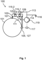
- Fig. 1 shows a schematic representation of a laundry device 100 according to an embodiment.
- the laundry device 100 which is only schematically shown in Fig. 1 , comprises a schematically shown drying chamber 101 for drying laundry, which may be arranged in an interior space of the laundry device 100.
- a drying program of the laundry device 100 for performing a laundry treatment process wet laundry, which may be received in the drying chamber 101, may be treated and afterwards the treated laundry may be taken out by the user from the drying chamber 101.
- the laundry may give off moisture and impurities, in particular fluff, to the air in the drying chamber 101.
- the laundry device 100 comprises an air channel 103.
- the air channel 103 is connected with the drying chamber 101 via an air inlet 105 and an air outlet 107.
- the air inlet 105 is configured to feed air from the drying chamber 101 into the air channel 103.
- the air outlet 107 is configured to feed the air from the air channel 103 back into the drying chamber 101.
- a fan 127 may be arranged in the air channel 103, which is configured to feed the air from the air inlet 105 into the air channel 103 and out of the air outlet 107.
- An evaporator 109 is arranged downstream of the air inlet 105 in the air channel 103.
- the evaporator 109 may be arranged in a heat cycle of a heat pump, wherein a cooling means is circulating in the heat cycle of the heat pump, which cooling means is configured to cool down the evaporator 109.
- the evaporator 109 is configured to cool down the air supplied by the air inlet 105 to condense water at the evaporator 109 during cooling of the air. Impurities, in particular fluff, in the air are deposited at the evaporator 109.
- the laundry device 100 comprises a collection container 111 arranged below the evaporator 109.
- the collection container 111 is configured to collect the condensed water of the evaporator 109.
- the collection container 111 is fluidly connected via a pumping line 113 with at least one fluid diffuser 115-1, 115-2, which is arranged above the evaporator 109.
- the at least one fluid diffuser 115-1, 115-2 may comprise a first fluid diffuser 115-1 arranged above the evaporator 109 and configured to feed the pumped water onto the evaporator 109 to flush the impurities, in particular the fluff, from the evaporator 109 into the collection container 111.
- a condenser 125 may be arranged in the air channel 103 downstream of the evaporator 109.
- the condenser 125 may be configured to heat the air cooled by the evaporator 109. Further impurities, in particular further fluff, of the air may be deposited at the condenser 125.
- the collection container 111 may be arranged below the evaporator 109 and the condenser 125.
- the at least one fluid diffuser 115-1, 115-2 may comprise a second fluid diffuser 115-2 arranged above the condenser 125 and configured to feed the pumped water onto the condenser 125 to flush the further impurities, in particular further fluff, from the condenser 125 into the collection container 111.
- the laundry device 100 comprises a pump 119 configured to pump the water collected in the collection container 111 via the pumping line 113 into the at least one fluid diffuser 115-1, 115-2.
- the at least one fluid diffuser 115-1, 115-2 is configured to feed the pumped water onto the evaporator 109 to flush the impurities, in particular the fluff, from the evaporator 109 into the collection container 111.
- a pump-out line 114 may be fluidly connected to the collection container 111 to remove water and the impurities, in particular the fluff, from the collection container 111 into a drain 116.
- the laundry device 100 may comprise a control 117.
- the control 117 may be configured to activate the pump 119 to pump the water collected in the collection container 111 via the pumping line 113 into the at least one fluid diffuser 115-1, 115-2.
- the control 117 may be configured to activate the pump 119 to pump the water collected in the collection container 111 via the pumping line 113 into the at least one fluid diffuser 115-1, 115-2 when a moisture level of the laundry accommodated in the drying chamber 101 falls below a predetermined moisture level threshold during the drying program of the laundry device 100.
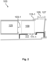
- Fig. 2 shows a schematic representation of an air channel 103 of a laundry device 100 according to an embodiment.
- the laundry device 100 may be the laundry device 100 of Fig. 1 .
- the laundry device 100 comprises a drying chamber 101, an evaporator 109, at least one fluid diffuser 115-1, an air inlet 105, an air outlet 107, a fan 127, a condenser 125, and a collection container 111.
- Fig. 2 schematically shows an air flow direction 103-1 of the air in the air channel 103.
- Warm and wet air from the drying chamber 101 enters the air channel 103 through the air inlet 105, in which the fan 127 may be arranged and then passes the evaporator 109.
- the air is cooled down and a moisture level of the air is reduced by condensation of water on the evaporator 109. Then the air passes the condenser 125 at which the air is heated again.
- the air then enters the drying chamber 101 through the air outlet 107 (not shown in Fig. 2 ).
- the collection container 111 may be arranged below the evaporator 109 and the air channel 103 to collect the water condensed at the evaporator 109 and the pumped water flushed by the at least one diffuser 115-1.
- the collection container 111 may comprise openings 111-1 for passing the condensed water and the pumped water into the collection container 111.
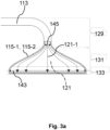
- Fig. 3a schematically shows a top view of a fluid diffuser 115-1, 115-2 of the laundry device 100 according to an embodiment.
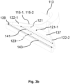
- Fig. 3b schematically shows a 3D-view of the fluid diffuser 115-1, 115-2
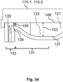
- Fig. 3c and 3d schematically show cross section views of the fluid diffuser 115-1, 115-2.
- the laundry device 100 may be the laundry device 100 of Fig. 1 .
- the fluid diffuser 115-1, 115-2 is described with reference to the Figures 3a-3d .
- the at least one fluid diffuser 115-1, 115-2 comprises an inner flow channel 121 for conducting the pumped water.
- the flow channel 121 comprises an inlet section 129, an intermediate section 131 and an outlet section 133.
- the pumped water enters the at least one diffuser 115-1, 115-2 through the inlet section 129, flows through the intermediate section 131 along a flow direction 121-1 and exits the at least one diffuser 115-1, 115-2 through the outlet section 133.
- a recess 123 is formed in the intermediate section at a bottom wall 137 of the flow channel 121.
- the recess 123 extends over a first width 141, in particular the entire first width 141, of the flow channel 121 between two side walls 122-1, 122-2 of the flow channel 121.
- a top wall 149 of the flow channel 121 may be parallel to a bottom wall of the recess 123 along a section of the intermediate section 131.
- the recess 123 may be formed as a concave recess in the flow channel 121.
- an elevation 139 of the bottom wall 137 may be formed in the flow channel 121.
- the elevation 139 is adapted to dam up the pumped water and allow the pumped water to flow over the elevation 139 along a second width 143, in particular along the entire second width 143, of the flow channel 121 between the two side walls 122-1, 122-2 of the flow channel 121.
- the flow channel 121 may have a third width 145 at the inlet section 129 between the two side walls 122-1, 122-2 of the flow channel 121.
- the third width 145 may be smaller than the first width 141, in particular a width of the flow channel 121 may be continuously increasing from the third width 145 along the flow direction 121-1 to the first width 141.
- the first width 141 of the flow channel 121 may be smaller than the second width 143 of the flow channel 121, in particular a width of the flow channel 121 may be continuously increasing from the first width 141 along the flow direction 121-1 to the second width 143.
- the flow channel 121 may have a first height 147 at the inlet section 129 between the bottom wall 137 of the flow channel 121 and a top wall 149 of the flow channel 121.
- the flow channel 121 may have a second height 151 in the intermediate section 131 of the flow channel upstream of the recess 123 between the bottom wall 137 of the flow channel 121 and the top wall 149 of the flow channel 121.
- the second height 151 of the flow channel 121 may be smaller than the first height 147 of the flow channel 121, in particular a height of the flow channel 121 may be continuously decreasing from the first height 147 along the flow direction 121-1 to the second height 151.
- the flow channel 121 may have a third height 153 between a bottom wall 137 of the recess 123 and the top wall 149 of the flow channel 121.
- the second height 151 of the flow channel 121 may be smaller than the third height 153 of the flow channel 121, in particular the height of the flow channel 121 may be continuously increasing from the second height 151 along the flow direction 121-1 to the third height 153.
- the flow channel 121 may have a fourth height 155 at the elevation 139 between the bottom wall 137 of the flow channel 121 and the top wall 149 of the flow channel 121.
- the fourth height 155 of the flow channel 121 may be smaller than the third height 153 of the flow channel 121, in particular a height of the flow channel 121 may be continuously decreasing from the third height 153 along the flow direction to the fourth height 155.
- the outlet section 133 may comprise a water outlet channel 135 extending downwards.
- a width of the water outlet channel 135 between the two side walls of the flow channel 121 at the outlet section 133 may correspond to the second width 143 of the flow channel 121.
- the flow channel 121 and the water outlet channel 135 may be arranged in an angle between 80° and 100°, in particular 90°, to each other and/or the flow channel 121 and the water outlet channel 135 may be connected by a rounded edge.
- Fig. 4 shows a diagram illustrating the water distribution of the water flowing through the at least one diffuser 115-1, 115-2 at the outlet section 133 (shown in Figures 3a-3d ) of the laundry device 100 according to an embodiment.
- the abscissa shows different measurement points along the second width 143 (shown in Figures 3a-b ) and the ordinate shows values of the waterflow in g/mm/30sec.
- a first curve 157 shows the water distribution of a traditional diffuser.
- a second curve 159 shows a theoretical optimal water distribution.
- the traditional diffuser has an uneven water flow distribution, in particular at the outer measurement points near the side walls of the diffuser.
- a third curve 161 shows the water distribution of the water flowing through the at least one diffuser 115-1, 115-2 at the outlet section 133 of the laundry device 100.
- the at least one diffuser 115-1, 115-2 has a more even water flow distribution in comparison with the traditional diffuser and is close to the theoretical optimal water distribution.
Landscapes
- Engineering & Computer Science (AREA)
- Textile Engineering (AREA)
- Detail Structures Of Washing Machines And Dryers (AREA)
Abstract
Laundry device, wherein the laundry device comprises at least one fluid diffuser configured to feed pumped water onto an evaporator to flush impurities, in particular fluff, from the evaporator into a collection container, wherein the at least one fluid diffuser comprises an inner flow channel for conducting the pumped water, wherein the flow channel comprises an inlet section, an intermediate section and an outlet section, wherein the pumped water enters the at least one diffuser through the inlet section, flows through the intermediate section along a flow direction and exits the at least one diffuser through the outlet section, wherein a recess is formed in the intermediate section at a bottom wall of the flow channel, wherein the recess extends over a first width of the flow channel between two side walls of the flow channel, wherein downstream of the recess in the outlet section an elevation of the bottom wall is formed in the flow channel, wherein the elevation is adapted to dam up the pumped water and allow the pumped water to flow over the elevation along a second width of the flow channel between the two side walls of the flow channel.
Description
- The present disclosure relates to a laundry device comprising a diffuser, in particular to a dryer or wash-dryer comprising a diffuser.
- In conventional laundry devices, such as dryers or wash-dryers, wet laundry is introduced into a laundry drum. During a drying process, liquid content of the wet laundry has to be reduced, for example, by removing liquid from the laundry. Typically, in conventional laundry devices, in particular in conventional laundry devices with a heat pump, an evaporator of a heat exchange mechanism is provided to reduce the humidity of air circulating in the drying process. During the drying process, impurities of the laundry, such as fluff, can be accommodated in the circulating air and can accumulate on the evaporator, thereby reducing the efficiency of the heat exchange mechanism and the drying process of the laundry.
- It is therefore an object of the present disclosure to provide a laundry device, in particular a dryer or wash-dryer, which allows efficient drying of laundry.
- This object is achieved by way of the features of the independent patent claim. Advantageous developments are the subject matter of the dependent claims, the description, and the appended figures.
- According to a first aspect, the present disclosure relates to a laundry device, wherein the laundry device comprises a drying chamber for drying laundry and an air channel, wherein the air channel is connected with the drying chamber via an air inlet and an air outlet, wherein the air inlet is configured to feed air from the drying chamber into the air channel, wherein the air outlet is configured to feed the air from the air channel back into the drying chamber, wherein an evaporator is arranged downstream of the air inlet in the air channel, wherein the evaporator is configured to cool down the air supplied by the air inlet to condense water at the evaporator during cooling of the air, wherein impurities, in particular fluff, in the air are deposited at the evaporator, wherein the laundry device comprises a collection container arranged below the evaporator, wherein the collection container is configured to collect the condensed water of the evaporator, wherein the collection container is fluidly connected via a pumping line with at least one fluid diffuser, which is arranged above the evaporator, wherein the laundry device comprises a pump configured to pump the water collected in the collection container via the pumping line into the at least one fluid diffuser, wherein the at least one fluid diffuser is configured to feed the pumped water onto the evaporator to flush the impurities, in particular the fluff, from the evaporator into the collection container, wherein the at least one fluid diffuser comprises an inner flow channel for conducting the pumped water, wherein the flow channel comprises an inlet section, an intermediate section and an outlet section, wherein the pumped water enters the at least one diffuser through the inlet section, flows through the intermediate section along a flow direction and exits the at least one diffuser through the outlet section, wherein a recess is formed in the intermediate section at a bottom wall of the flow channel, wherein the recess extends over a first width of the flow channel between two side walls of the flow channel, wherein downstream of the recess in the outlet section an elevation of the bottom wall is formed in the flow channel, wherein the elevation is adapted to dam up the pumped water and allow the pumped water to flow over the elevation along a second width of the flow channel between the two side walls of the flow channel.
- As a result, the pumped water can be distributed evenly along the second width of the flow channel at the elevation and can evenly flow over the elevation. Therefore, the impurities, in particular the fluff, can be flushed efficiently from the evaporator into the collection container.
- A control of the laundry device may be configured to switch a ventil of the pump-out line and activate the pump to pump water together with the impurities, in particular the fluff, out of the collection container through the pump-out line.
- The laundry device according to the present disclosure in particular refers to a laundry device which is adapted to dry laundry, in particular by thereby removing or at least significantly reducing the amount of water attached to the laundry. In particular, the laundry device according to the present disclosure is a dryer, which is adapted to dry laundry. More particular, the laundry device according to the present disclosure is a heatpump tumble dryer.
- According to an embodiment, a fan is arranged in the air channel, which is configured to feed the air from the air inlet into the air channel and out of the air outlet.
- As a result, the air can be efficiently fed through the air channel. The fan may be arranged in the air inlet.
- According to an embodiment, the evaporator is arranged in a heat cycle of a heat pump, wherein a cooling means is circulating in the heat cycle of the heat pump, which cooling means is configured to cool down the evaporator.
- As a result, the evaporator can be efficiently operated. The heat cycle may further comprise a condenser for heating air, a compressor for increasing the temperature and the pressure of the cooling means and an expansion valve for reducing the temperature and the pressure of the cooling means. The expansion valve may be arranged downstream of the condenser in the heat cycle. The evaporator may be arranged downstream of the expansion valve in the heat cycle. The compressor may be arranged downstream of the evaporator in the heat cycle. The condenser may be arranged downstream of the compressor in the heat cycle.
- According to an embodiment, the at least one fluid diffuser comprises a first fluid diffuser arranged above a section of the evaporator and a further first fluid diffuser arranged above a further section of the evaporator, wherein the first fluid diffuser is configured to feed the pumped water onto the section of the evaporator to flush the impurities, in particular the fluff, from the section of the evaporator into the collection container, wherein the further first fluid diffuser is configured to feed the pumped water onto the further section of the evaporator to flush the impurities, in particular the fluff, from the further section of the evaporator into the collection container, wherein a first valve is arranged in the pumping line, wherein the pumping line is connected to the first fluid diffuser in a first state of the first valve and wherein the pumping line is connected to the further first fluid diffuser in a second state of the first valve.
- As a result, more effective evaporators, i.e. evaporators with greater dimensions, can be efficiently used in the laundry device. The first valve may be controlled by a control of the laundry device in order to flush a different section of the evaporator.
- According to an embodiment, the at least one fluid diffuser comprises a first fluid diffuser arranged above the evaporator and configured to feed the pumped water onto the evaporator to flush the impurities, in particular the fluff, from the evaporator into the collection container, wherein a condenser is arranged in the air channel downstream of the evaporator, wherein the condenser is configured to heat the air cooled by the evaporator, wherein further impurities, in particular further fluff, of the air are deposited at the condenser, wherein the collection container is arranged below the evaporator and the condenser, wherein the at least one fluid diffuser comprises a second fluid diffuser arranged above the condenser and configured to feed the pumped water onto the condenser to flush the further impurities, in particular further fluff, from the condenser into the collection container.
- As a result, the efficiency of the condenser can be increased as well by cleaning it from the further impurities, in particular the further fluff. A valve may be controlled by a control of the laundry device in order to switch between flushing the condenser and flushing the evaporator.
- According to an embodiment, the condenser is arranged in a heat cycle of a heat pump, wherein a cooling means is circulating in the heat cycle of the heat pump, which cooling means is configured to heat the condenser.
- As a result, the condenser can be efficiently operated. The heat cycle may further comprise a compressor for increasing the temperature and the pressure of the cooling means and an expansion valve for reducing the temperature and the pressure of the cooling means. The expansion valve may be arranged downstream of the condenser in the heat cycle. The evaporator may be arranged downstream of the expansion valve in the heat cycle. The compressor may be arranged downstream of the evaporator in the heat cycle. The condenser may be arranged downstream of the compressor in the heat cycle.
- According to an embodiment, the at least one fluid diffuser comprises a second fluid diffuser arranged above a section of the condenser and a further second fluid diffuser arranged above a further section of the condenser, wherein the second fluid diffuser is configured to feed the pumped water onto the section of the condenser to flush the impurities, in particular the fluff, from the section of the condenser into the collection container, wherein the further second fluid diffuser is configured to feed the pumped water onto the further section of the condenser to flush the impurities, in particular the fluff, from the further section of the condenser into the collection container, wherein a second valve is arranged in the pumping line, wherein the pumping line is connected to the second fluid diffuser in a first state of the second valve and wherein the pumping line is connected to the further second fluid diffuser in a second state of the second valve.
- As a result, more effective condensers, i.e. condensers with greater dimensions, can be efficiently used in the laundry device. The second valve may be controlled by a control of the laundry device in order to flush a different section of the condenser.
- According to an embodiment, the first width of the flow channel is smaller than the second width of the flow channel, in particular wherein a width of the flow channel is continuously increasing from the first width along the flow direction to the second width.
- As a result, the pumped water can efficiently flow in the flow channel from the first width to the second width along the flow direction.
- According to an embodiment, the flow channel has a third width at the inlet section between the two side walls of the flow channel, wherein the third width is smaller than the first width, in particular wherein a width of the flow channel is continuously increasing from the third width along the flow direction to the first width.
- As a result, the pumped water can efficiently flow in the flow channel from the third width to the first width along the flow direction.
- According to an embodiment, the flow channel has a first height at the inlet section between the bottom wall of the flow channel and a top wall of the flow channel, wherein the flow channel has a second height in the intermediate section of the flow channel upstream of the recess between the bottom wall of the flow channel and the top wall of the flow channel, wherein the second height of the flow channel is smaller than the first height of the flow channel, in particular wherein a height of the flow channel is continuously decreasing from the first height along the flow direction to the second height.
- As a result, the pumped water can efficiently flow in the flow channel from the first height to the second height along the flow direction. The first height may be a maximum height of the inlet section between the bottom wall of the flow channel and the top wall of the flow channel. The second height may be a minimum height of the intermediate section upstream of the recess between the bottom wall of the flow channel and the top wall of the flow channel.
- According to an embodiment, the flow channel has a second height in the intermediate section of the flow channel upstream of the recess between the bottom wall of the flow channel and the top wall of the flow channel, wherein the flow channel has a third height between a bottom wall of the recess and the top wall of the flow channel, wherein the second height of the flow channel is smaller than the third height of the flow channel, in particular wherein a height of the flow channel is continuously increasing from the second height along the flow direction to the third height.
- As a result, the pumped water can efficiently flow in the flow channel from the second height to the third height along the flow direction. The second height may be a minimum height of the intermediate section upstream of the recess between the bottom wall of the flow channel and the top wall of the flow channel. The third height may be a maximum height between the bottom wall of the recess and the top wall of the flow channel.
- According to an embodiment, a top wall of the flow channel is parallel to a bottom wall of the recess along a section of the intermediate section.
- As a result, the pumped water can efficiently flow in the flow channel in the recess along the flow direction.
- According to an embodiment, the flow channel has a fourth height at the elevation between the bottom wall of the flow channel and the top wall of the flow channel, wherein the flow channel has a third height between a bottom wall of the recess and the top wall of the flow channel, wherein the fourth height of the flow channel is smaller than the third height of the flow channel, in particular wherein a height of the flow channel is continuously decreasing from the third height along the flow direction to the fourth height.
- As a result, the pumped water can efficiently flow in the flow channel from the third height to the fourth height along the flow direction. The third height may be a maximum height between the bottom wall of the recess and the top wall of the flow channel. The fourth height may be a minimum height of the outlet section at the elevation between the bottom wall of the flow channel and the top wall of the flow channel.
- According to an embodiment, the outlet section comprises a water outlet channel extending downwards, wherein a width of the water outlet channel between two side walls of the flow channel at the outlet section corresponds to the second width of the flow channel.
- As a result, the pumped water can efficiently flow through the outlet section in the flow channel and out of the at least one diffuser over the evaporator, and in particular the condenser.
- According to an embodiment, the flow channel and the water outlet channel are arranged in an angle between 80° and 100°, in particular 90°, to each other and/or wherein the flow channel and the water outlet channel are connected by a rounded edge.
- As a result, the pumped water can efficiently flow out of the outlet section of the flow channel. The rounded edge may be adjacent to the elevation, in particular the elevation may merge into the rounded edge.
- According to an embodiment, the recess is formed as a concave recess in the flow channel.
- As a result, the pumped water can efficiently flow in the flow channel in the recess along the flow direction.
- According to an embodiment, the recess extends over the entire first width of the flow channel between the two side walls of the flow channel, and/or the elevation is adapted to allow the pumped water to flow over the elevation along the entire second width of the flow channel between the two side walls of the flow channel.
- As a result, the pumped water can efficiently flow in the flow channel in the recess along the flow direction.
- Further examples of the principles and techniques of that disclosure are explained in greater detail with reference to the appended drawings, in which:
-
Fig. 1 shows a schematic representation of a laundry device according to an embodiment; -
Fig. 2 shows a schematic representation of an air channel of a laundry device according to an embodiment; -
Fig. 3a schematically shows a top view of a fluid diffuser of a laundry device according to an embodiment; -
Fig. 3b schematically shows a 3D-view of the fluid diffuser shown inFig. 3a ; -
Fig. 3c and3d schematically shows cross section views of the fluid diffuser shown inFig. 3a ; and -
Fig. 4 shows a diagram illustrating the water distribution of the water flowing through a diffuser at an outlet section of a laundry device according to an embodiment. -
Fig. 1 shows a schematic representation of alaundry device 100 according to an embodiment. - The
laundry device 100, which is only schematically shown inFig. 1 , comprises a schematically shown dryingchamber 101 for drying laundry, which may be arranged in an interior space of thelaundry device 100. During a drying program of thelaundry device 100 for performing a laundry treatment process, wet laundry, which may be received in the dryingchamber 101, may be treated and afterwards the treated laundry may be taken out by the user from the dryingchamber 101. During the drying program, the laundry may give off moisture and impurities, in particular fluff, to the air in the dryingchamber 101. - As further shown in
Fig. 1 , thelaundry device 100 comprises anair channel 103. Theair channel 103 is connected with the dryingchamber 101 via an air inlet 105 and anair outlet 107. The air inlet 105 is configured to feed air from the dryingchamber 101 into theair channel 103. Theair outlet 107 is configured to feed the air from theair channel 103 back into the dryingchamber 101. A fan 127 may be arranged in theair channel 103, which is configured to feed the air from the air inlet 105 into theair channel 103 and out of theair outlet 107. - An
evaporator 109 is arranged downstream of the air inlet 105 in theair channel 103. Theevaporator 109 may be arranged in a heat cycle of a heat pump, wherein a cooling means is circulating in the heat cycle of the heat pump, which cooling means is configured to cool down theevaporator 109. Theevaporator 109 is configured to cool down the air supplied by the air inlet 105 to condense water at theevaporator 109 during cooling of the air. Impurities, in particular fluff, in the air are deposited at theevaporator 109. - The
laundry device 100 comprises acollection container 111 arranged below theevaporator 109. Thecollection container 111 is configured to collect the condensed water of theevaporator 109. Thecollection container 111 is fluidly connected via apumping line 113 with at least one fluid diffuser 115-1, 115-2, which is arranged above theevaporator 109. - The at least one fluid diffuser 115-1, 115-2 may comprise a first fluid diffuser 115-1 arranged above the
evaporator 109 and configured to feed the pumped water onto theevaporator 109 to flush the impurities, in particular the fluff, from theevaporator 109 into thecollection container 111. - A
condenser 125 may be arranged in theair channel 103 downstream of theevaporator 109. Thecondenser 125 may be configured to heat the air cooled by theevaporator 109. Further impurities, in particular further fluff, of the air may be deposited at thecondenser 125. Thecollection container 111 may be arranged below theevaporator 109 and thecondenser 125. The at least one fluid diffuser 115-1, 115-2 may comprise a second fluid diffuser 115-2 arranged above thecondenser 125 and configured to feed the pumped water onto thecondenser 125 to flush the further impurities, in particular further fluff, from thecondenser 125 into thecollection container 111. - The
condenser 125 may be arranged in the heat cycle of the heat pump. The cooling means may be configured to heat thecondenser 125. - The
laundry device 100 comprises apump 119 configured to pump the water collected in thecollection container 111 via thepumping line 113 into the at least one fluid diffuser 115-1, 115-2. The at least one fluid diffuser 115-1, 115-2 is configured to feed the pumped water onto theevaporator 109 to flush the impurities, in particular the fluff, from theevaporator 109 into thecollection container 111. A pump-outline 114 may be fluidly connected to thecollection container 111 to remove water and the impurities, in particular the fluff, from thecollection container 111 into adrain 116. - The
laundry device 100 may comprise acontrol 117. During a drying program of thelaundry device 100 or at the end of a drying program of thelaundry device 100, thecontrol 117 may be configured to activate thepump 119 to pump the water collected in thecollection container 111 via thepumping line 113 into the at least one fluid diffuser 115-1, 115-2. Thecontrol 117 may be configured to activate thepump 119 to pump the water collected in thecollection container 111 via thepumping line 113 into the at least one fluid diffuser 115-1, 115-2 when a moisture level of the laundry accommodated in the dryingchamber 101 falls below a predetermined moisture level threshold during the drying program of thelaundry device 100. -
Fig. 2 shows a schematic representation of anair channel 103 of alaundry device 100 according to an embodiment. Thelaundry device 100 may be thelaundry device 100 ofFig. 1 . As described forFig. 1 , thelaundry device 100 comprises a dryingchamber 101, anevaporator 109, at least one fluid diffuser 115-1, an air inlet 105, anair outlet 107, a fan 127, acondenser 125, and acollection container 111. -
Fig. 2 schematically shows an air flow direction 103-1 of the air in theair channel 103. Warm and wet air from the dryingchamber 101 enters theair channel 103 through the air inlet 105, in which the fan 127 may be arranged and then passes theevaporator 109. At theevaporator 109 the air is cooled down and a moisture level of the air is reduced by condensation of water on theevaporator 109. Then the air passes thecondenser 125 at which the air is heated again. The air then enters the dryingchamber 101 through the air outlet 107 (not shown inFig. 2 ). - As further shown in
Fig. 2 , thecollection container 111 may be arranged below theevaporator 109 and theair channel 103 to collect the water condensed at theevaporator 109 and the pumped water flushed by the at least one diffuser 115-1. Thecollection container 111 may comprise openings 111-1 for passing the condensed water and the pumped water into thecollection container 111. -
Fig. 3a schematically shows a top view of a fluid diffuser 115-1, 115-2 of thelaundry device 100 according to an embodiment.Fig. 3b schematically shows a 3D-view of the fluid diffuser 115-1, 115-2, andFig. 3c and3d schematically show cross section views of the fluid diffuser 115-1, 115-2. Thelaundry device 100 may be thelaundry device 100 ofFig. 1 . In the following, the fluid diffuser 115-1, 115-2 is described with reference to theFigures 3a-3d . - The at least one fluid diffuser 115-1, 115-2 comprises an
inner flow channel 121 for conducting the pumped water. Theflow channel 121 comprises aninlet section 129, anintermediate section 131 and anoutlet section 133. The pumped water enters the at least one diffuser 115-1, 115-2 through theinlet section 129, flows through theintermediate section 131 along a flow direction 121-1 and exits the at least one diffuser 115-1, 115-2 through theoutlet section 133. - A
recess 123 is formed in the intermediate section at abottom wall 137 of theflow channel 121. Therecess 123 extends over afirst width 141, in particular the entirefirst width 141, of theflow channel 121 between two side walls 122-1, 122-2 of theflow channel 121. - A
top wall 149 of theflow channel 121 may be parallel to a bottom wall of therecess 123 along a section of theintermediate section 131. Alternatively, therecess 123 may be formed as a concave recess in theflow channel 121. - Downstream of the
recess 123 in theoutlet section 133 anelevation 139 of thebottom wall 137 may be formed in theflow channel 121. Theelevation 139 is adapted to dam up the pumped water and allow the pumped water to flow over theelevation 139 along asecond width 143, in particular along the entiresecond width 143, of theflow channel 121 between the two side walls 122-1, 122-2 of theflow channel 121. - The
flow channel 121 may have athird width 145 at theinlet section 129 between the two side walls 122-1, 122-2 of theflow channel 121. Thethird width 145 may be smaller than thefirst width 141, in particular a width of theflow channel 121 may be continuously increasing from thethird width 145 along the flow direction 121-1 to thefirst width 141. - The
first width 141 of theflow channel 121 may be smaller than thesecond width 143 of theflow channel 121, in particular a width of theflow channel 121 may be continuously increasing from thefirst width 141 along the flow direction 121-1 to thesecond width 143. - The
flow channel 121 may have afirst height 147 at theinlet section 129 between thebottom wall 137 of theflow channel 121 and atop wall 149 of theflow channel 121. Theflow channel 121 may have asecond height 151 in theintermediate section 131 of the flow channel upstream of therecess 123 between thebottom wall 137 of theflow channel 121 and thetop wall 149 of theflow channel 121. Thesecond height 151 of theflow channel 121 may be smaller than thefirst height 147 of theflow channel 121, in particular a height of theflow channel 121 may be continuously decreasing from thefirst height 147 along the flow direction 121-1 to thesecond height 151. - The
flow channel 121 may have athird height 153 between abottom wall 137 of therecess 123 and thetop wall 149 of theflow channel 121. Thesecond height 151 of theflow channel 121 may be smaller than thethird height 153 of theflow channel 121, in particular the height of theflow channel 121 may be continuously increasing from thesecond height 151 along the flow direction 121-1 to thethird height 153. - The
flow channel 121 may have afourth height 155 at theelevation 139 between thebottom wall 137 of theflow channel 121 and thetop wall 149 of theflow channel 121. Thefourth height 155 of theflow channel 121 may be smaller than thethird height 153 of theflow channel 121, in particular a height of theflow channel 121 may be continuously decreasing from thethird height 153 along the flow direction to thefourth height 155. - The
outlet section 133 may comprise awater outlet channel 135 extending downwards. A width of thewater outlet channel 135 between the two side walls of theflow channel 121 at theoutlet section 133 may correspond to thesecond width 143 of theflow channel 121. Theflow channel 121 and thewater outlet channel 135 may be arranged in an angle between 80° and 100°, in particular 90°, to each other and/or theflow channel 121 and thewater outlet channel 135 may be connected by a rounded edge. -
Fig. 4 shows a diagram illustrating the water distribution of the water flowing through the at least one diffuser 115-1, 115-2 at the outlet section 133 (shown inFigures 3a-3d ) of thelaundry device 100 according to an embodiment. The abscissa shows different measurement points along the second width 143 (shown inFigures 3a-b ) and the ordinate shows values of the waterflow in g/mm/30sec. - A
first curve 157 shows the water distribution of a traditional diffuser. Asecond curve 159 shows a theoretical optimal water distribution. As can be seen by the comparison of thefirst curve 157 with thesecond curve 159, the traditional diffuser has an uneven water flow distribution, in particular at the outer measurement points near the side walls of the diffuser. - A
third curve 161 shows the water distribution of the water flowing through the at least one diffuser 115-1, 115-2 at theoutlet section 133 of thelaundry device 100. As can be seen by the comparison of thethird curve 161 with thesecond curve 159 and thefirst curve 157, the at least one diffuser 115-1, 115-2 has a more even water flow distribution in comparison with the traditional diffuser and is close to the theoretical optimal water distribution. -
- 100
- laundry device
- 101
- drying chamber
- 103
- air channel
- 103-1
- air flow direction in the air channel
- 105
- air inlet
- 107
- air outlet
- 109
- evaporator
- 111
- collection container
- 111-1
- openings
- 113
- pumping line
- 114
- pump-out line
- 115-1
- first fluid diffuser
- 115-2
- second fluid diffuser
- 116
- drain
- 117
- control
- 119
- pump
- 121
- flow channel
- 121-1
- flow direction in the flow channel
- 122-1
- first side wall
- 122-2
- second side wall
- 123
- recess
- 125
- condenser
- 127
- fan
- 129
- inlet section
- 131
- intermediate section
- 133
- outlet section
- 135
- water outlet channel
- 137
- bottom wall
- 139
- elevation
- 141
- first width
- 143
- second width
- 145
- third width
- 147
- first height
- 149
- top wall
- 151
- second height
- 153
- third height
- 155
- fourth height
- 157
- first curve
- 159
- second curve
- 161
- third curve
Claims (15)
- Laundry device (100), wherein the laundry device (100) comprises a drying chamber (101) for drying laundry and an air channel (103), wherein the air channel (103) is connected with the drying chamber (101) via an air inlet (105) and an air outlet (107), wherein the air inlet (105) is configured to feed air from the drying chamber (101) into the air channel (103), wherein the air outlet (107) is configured to feed the air from the air channel (103) back into the drying chamber (101), wherein an evaporator (109) is arranged downstream of the air inlet (105) in the air channel (103), wherein the evaporator (109) is configured to cool down the air supplied by the air inlet (105) to condense water at the evaporator (109) during cooling of the air, wherein impurities, in particular fluff, in the air are deposited at the evaporator (109), wherein the laundry device (100) comprises a collection container (111) arranged below the evaporator (109), wherein the collection container (111) is configured to collect the condensed water of the evaporator (109), wherein the collection container (111) is fluidly connected via a pumping line (113) with at least one fluid diffuser (115-1, 115-2), which is arranged above the evaporator (109),wherein the laundry device (100) comprises a pump (119) configured to pump the water collected in the collection container (111) via the pumping line (113) into the at least one fluid diffuser (115-1, 115-2), wherein the at least one fluid diffuser (115-1, 115-2) is configured to feed the pumped water onto the evaporator (109) to flush the impurities, in particular the fluff, from the evaporator (109) into the collection container (111),wherein the at least one fluid diffuser (115-1, 115-2) comprises an inner flow channel (121) for conducting the pumped water, wherein the flow channel (121) comprises an inlet section (129), an intermediate section (131) and an outlet section (133), wherein the pumped water enters the at least one diffuser (115-1, 115-2) through the inlet section (129), flows through the intermediate section (131) along a flow direction and exits the at least one diffuser (115-1, 115-2) through the outlet section (133),characterized in that a recess (123) is formed in the intermediate section at a bottom wall (137) of the flow channel (121), wherein the recess (123) extends over a first width (141) of the flow channel (121) between two side walls (122-1, 122-2) of the flow channel (121), wherein downstream of the recess (123) in the outlet section (133) an elevation (139) of the bottom wall (137) is formed in the flow channel (121), wherein the elevation (139) is adapted to dam up the pumped water and allow the pumped water to flow over the elevation (139) along a second width (143) of the flow channel (121) between the two side walls (122-1, 122-2) of the flow channel (121).
- Laundry device (100) according to claim 1, wherein a fan (127) is arranged in the air channel (103), which is configured to feed the air from the air inlet (105) into the air channel (103) and out of the air outlet (107).
- Laundry device (100) according to claim 1 or 2, wherein the evaporator (109) is arranged in a heat cycle of a heat pump, wherein a cooling means is circulating in the heat cycle of the heat pump, which cooling means is configured to cool down the evaporator (109).
- Laundry device (100) according to according to any one of the preceding claims, wherein the at least one fluid diffuser (115-1, 115-2) comprises a first fluid diffuser (115-1) arranged above the evaporator (109) and configured to feed the pumped water onto the evaporator (109) to flush the impurities, in particular the fluff, from the evaporator (109) into the collection container (111),
wherein a condenser (125) is arranged in the air channel (103) downstream of the evaporator (109), wherein the condenser (125) is configured to heat the air cooled by the evaporator (109), wherein further impurities, in particular further fluff, of the air are deposited at the condenser (125), wherein the collection container (111) is arranged below the evaporator (109) and the condenser (125), wherein the at least one fluid diffuser (115-1, 115-2) comprises a second fluid diffuser (115-2) arranged above the condenser (125) and configured to feed the pumped water onto the condenser (125) to flush the further impurities, in particular further fluff, from the condenser (125) into the collection container (111). - Laundry device (100) according to claim 4, wherein the condenser (125) is arranged in a heat cycle of a heat pump, wherein a cooling means is circulating in the heat cycle of the heat pump, which cooling means is configured to heat the condenser (125).
- Laundry device according to any one of the preceding claims, wherein the first width (141) of the flow channel (121) is smaller than the second width (143) of the flow channel (121), in particular wherein a width of the flow channel (121) is continuously increasing from the first width (141) along the flow direction to the second width (143).
- Laundry device according to any one of the preceding claims, wherein the flow channel (121) has a third width (145) at the inlet section (129) between the two side walls (122-1, 122-2) of the flow channel (121), wherein the third width (145) is smaller than the first width (141), in particular wherein a width of the flow channel (121) is continuously increasing from the third width (145) along the flow direction to the first width (141).
- Laundry device according to any one of the preceding claims, wherein the flow channel (121) has a first height (147) at the inlet section (129) between the bottom wall (137) of the flow channel (121) and a top wall (149) of the flow channel (121), wherein the flow channel (121) has a second height (151) in the intermediate section (131) of the flow channel upstream of the recess (123) between the bottom wall (137) of the flow channel (121) and the top wall (149) of the flow channel (121), wherein the second height (151) of the flow channel (121) is smaller than the first height (147) of the flow channel (121), in particular wherein a height of the flow channel (121) is continuously decreasing from the first height (147) along the flow direction to the second height (151).
- Laundry device according to one of the preceding claims, wherein the flow channel (121) has a second height (151) in the intermediate section (131) of the flow channel upstream of the recess (123) between the bottom wall (137) of the flow channel (121) and the top wall (149) of the flow channel (121), wherein the flow channel (121) has a third height (153) between a bottom wall (137) of the recess (123) and the top wall (149) of the flow channel (121), wherein the second height (151) of the flow channel (121) is smaller than the third height (153) of the flow channel (121), in particular wherein a height of the flow channel (121) is continuously increasing from the second height (151) along the flow direction to the third height (153).
- Laundry device according to any one of the preceding claims, wherein a top wall (149) of the flow channel (121) is parallel to a bottom wall of the recess (123) along a section of the intermediate section (131).
- Laundry device according to any one of the preceding claims, wherein the flow channel (121) has a fourth height (155) at the elevation (139) between the bottom wall (137) of the flow channel (121) and the top wall (149) of the flow channel (121), wherein the flow channel (121) has a third height (153) between a bottom wall (137) of the recess (123) and the top wall (149) of the flow channel (121), wherein the fourth height (155) of the flow channel (121) is smaller than the third height (153) of the flow channel (121), in particular wherein a height of the flow channel (121) is continuously decreasing from the third height (153) along the flow direction to the fourth height (155).
- Laundry device according to any one of the preceding claims, wherein the outlet section (133) comprises a water outlet channel (135) extending downwards, wherein a width of the water outlet channel (135) between two side walls (122-1, 122-2) of the flow channel (121) at the outlet section (133) corresponds to the second width (143) of the flow channel (121).
- Laundry device according to claim 12, wherein the flow channel (121) and the water outlet channel (135) are arranged in an angle between 80° and 100°, in particular 90°, to each other and/or wherein the flow channel (121) and the water outlet channel (135) are connected by a rounded edge.
- Laundry device according to any one of the preceding claims, wherein the recess (123) is formed as a concave recess in the flow channel (121).
- Laundry device according to any one of the preceding claims, wherein the recess (123) extends over the entire first width (141) of the flow channel (121) between the two side walls (122-1, 122-2) of the flow channel (121), and/or wherein the elevation is adapted to allow the pumped water to flow over the elevation (139) along the entire second width (143) of the flow channel (121) between the two side walls (122-1, 122-2) of the flow channel (121).
Priority Applications (2)
| Application Number | Priority Date | Filing Date | Title |
|---|---|---|---|
| EP23218517.3A EP4575076A1 (en) | 2023-12-20 | 2023-12-20 | Laundry drying device comprising a fluid diffuser arranged above an evaporator in the drying air channel |
| CN202411868655.0A CN120174610A (en) | 2023-12-20 | 2024-12-18 | Laundry device including diffuser |
Applications Claiming Priority (1)
| Application Number | Priority Date | Filing Date | Title |
|---|---|---|---|
| EP23218517.3A EP4575076A1 (en) | 2023-12-20 | 2023-12-20 | Laundry drying device comprising a fluid diffuser arranged above an evaporator in the drying air channel |
Publications (1)
| Publication Number | Publication Date |
|---|---|
| EP4575076A1 true EP4575076A1 (en) | 2025-06-25 |
Family
ID=89224303
Family Applications (1)
| Application Number | Title | Priority Date | Filing Date |
|---|---|---|---|
| EP23218517.3A Pending EP4575076A1 (en) | 2023-12-20 | 2023-12-20 | Laundry drying device comprising a fluid diffuser arranged above an evaporator in the drying air channel |
Country Status (2)
| Country | Link |
|---|---|
| EP (1) | EP4575076A1 (en) |
| CN (1) | CN120174610A (en) |
Citations (4)
| Publication number | Priority date | Publication date | Assignee | Title |
|---|---|---|---|---|
| EP2691567B1 (en) * | 2011-03-29 | 2016-11-23 | LG Electronics Inc. | Clothes treating apparatus having heat exchanger cleaning device |
| US20190024299A1 (en) * | 2015-09-03 | 2019-01-24 | Samsung Electronics Co., Ltd. | Clothes dryer |
| EP3725939A1 (en) * | 2012-09-14 | 2020-10-21 | Electrolux Home Products Corporation N.V. | Home appliance with a liquid guiding device |
| WO2022025551A1 (en) * | 2020-07-29 | 2022-02-03 | Lg Electronics Inc. | Laundry treating apparatus |
-
2023
- 2023-12-20 EP EP23218517.3A patent/EP4575076A1/en active Pending
-
2024
- 2024-12-18 CN CN202411868655.0A patent/CN120174610A/en active Pending
Patent Citations (4)
| Publication number | Priority date | Publication date | Assignee | Title |
|---|---|---|---|---|
| EP2691567B1 (en) * | 2011-03-29 | 2016-11-23 | LG Electronics Inc. | Clothes treating apparatus having heat exchanger cleaning device |
| EP3725939A1 (en) * | 2012-09-14 | 2020-10-21 | Electrolux Home Products Corporation N.V. | Home appliance with a liquid guiding device |
| US20190024299A1 (en) * | 2015-09-03 | 2019-01-24 | Samsung Electronics Co., Ltd. | Clothes dryer |
| WO2022025551A1 (en) * | 2020-07-29 | 2022-02-03 | Lg Electronics Inc. | Laundry treating apparatus |
Also Published As
| Publication number | Publication date |
|---|---|
| CN120174610A (en) | 2025-06-20 |
Similar Documents
| Publication | Publication Date | Title |
|---|---|---|
| US20260035853A1 (en) | Clothes treating apparatus having drying function | |
| CN110331566B (en) | Drying system and using method thereof | |
| KR102343262B1 (en) | Laundry Treating Apparatus | |
| EP3190227B1 (en) | Garment processing apparatus | |
| US7866057B2 (en) | Domestic appliance for the care of washed articles | |
| KR100456953B1 (en) | Drum type washing machine having drying device | |
| KR101192047B1 (en) | Clothes dryer | |
| KR20120110498A (en) | Clothes treating apparatus with a heat exchanger cleaning means | |
| KR20140109119A (en) | Laundry Treating Device | |
| KR20120110497A (en) | Cleaning nozzle for a heat exchanger and heat exchanger cleaning apparatus using the same | |
| KR20190128484A (en) | Clothes treating apparatus | |
| KR102742785B1 (en) | laundry treatment apparatus and control method thereof | |
| EP4575075A1 (en) | Laundry drying device comprising a fluid diffuser arranged above an evaporator in the drying air channe | |
| KR20210020406A (en) | laundry treatment apparatus | |
| JP4352803B2 (en) | Washing and drying machine | |
| KR20100032225A (en) | Clothes processor | |
| CN113957682A (en) | Condensing unit and clothes treatment equipment with same | |
| EP4560067A1 (en) | Laundry device comprising a control | |
| CN120174610A (en) | Laundry device including diffuser | |
| KR20210010144A (en) | laundry treatment apparatus and control method thereof | |
| JP2008183307A (en) | Laundry drier | |
| KR20120110499A (en) | Cleaning nozzle for a heat exchanger and heat exchanger cleaning apparatus using the same | |
| KR20040052299A (en) | Drum type washing machine having drying device | |
| KR100664285B1 (en) | Clothes dryer | |
| CN107130398B (en) | Dehumidifier for washing machine and the washing machine with it |
Legal Events
| Date | Code | Title | Description |
|---|---|---|---|
| PUAI | Public reference made under article 153(3) epc to a published international application that has entered the european phase |
Free format text: ORIGINAL CODE: 0009012 |
|
| STAA | Information on the status of an ep patent application or granted ep patent |
Free format text: STATUS: THE APPLICATION HAS BEEN PUBLISHED |
|
| AK | Designated contracting states |
Kind code of ref document: A1 Designated state(s): AL AT BE BG CH CY CZ DE DK EE ES FI FR GB GR HR HU IE IS IT LI LT LU LV MC ME MK MT NL NO PL PT RO RS SE SI SK SM TR |
|
| STAA | Information on the status of an ep patent application or granted ep patent |
Free format text: STATUS: REQUEST FOR EXAMINATION WAS MADE |
|
| 17P | Request for examination filed |
Effective date: 20260102 |