EP4575008A1 - Thick steel sheet and method for producing same - Google Patents
Thick steel sheet and method for producing same Download PDFInfo
- Publication number
- EP4575008A1 EP4575008A1 EP23854722.8A EP23854722A EP4575008A1 EP 4575008 A1 EP4575008 A1 EP 4575008A1 EP 23854722 A EP23854722 A EP 23854722A EP 4575008 A1 EP4575008 A1 EP 4575008A1
- Authority
- EP
- European Patent Office
- Prior art keywords
- less
- steel plate
- cooling
- content
- mass
- Prior art date
- Legal status (The legal status is an assumption and is not a legal conclusion. Google has not performed a legal analysis and makes no representation as to the accuracy of the status listed.)
- Pending
Links
Images
Classifications
-
- C—CHEMISTRY; METALLURGY
- C21—METALLURGY OF IRON
- C21D—MODIFYING THE PHYSICAL STRUCTURE OF FERROUS METALS; GENERAL DEVICES FOR HEAT TREATMENT OF FERROUS OR NON-FERROUS METALS OR ALLOYS; MAKING METAL MALLEABLE, e.g. BY DECARBURISATION OR TEMPERING
- C21D8/00—Modifying the physical properties of ferrous metals or ferrous alloys by deformation combined with, or followed by, heat treatment
- C21D8/02—Modifying the physical properties of ferrous metals or ferrous alloys by deformation combined with, or followed by, heat treatment during manufacturing of plates or strips
- C21D8/0247—Modifying the physical properties of ferrous metals or ferrous alloys by deformation combined with, or followed by, heat treatment during manufacturing of plates or strips characterised by the heat treatment
- C21D8/0263—Modifying the physical properties of ferrous metals or ferrous alloys by deformation combined with, or followed by, heat treatment during manufacturing of plates or strips characterised by the heat treatment following hot rolling
-
- C—CHEMISTRY; METALLURGY
- C21—METALLURGY OF IRON
- C21D—MODIFYING THE PHYSICAL STRUCTURE OF FERROUS METALS; GENERAL DEVICES FOR HEAT TREATMENT OF FERROUS OR NON-FERROUS METALS OR ALLOYS; MAKING METAL MALLEABLE, e.g. BY DECARBURISATION OR TEMPERING
- C21D1/00—General methods or devices for heat treatment, e.g. annealing, hardening, quenching or tempering
- C21D1/18—Hardening; Quenching with or without subsequent tempering
- C21D1/19—Hardening; Quenching with or without subsequent tempering by interrupted quenching
-
- C—CHEMISTRY; METALLURGY
- C21—METALLURGY OF IRON
- C21D—MODIFYING THE PHYSICAL STRUCTURE OF FERROUS METALS; GENERAL DEVICES FOR HEAT TREATMENT OF FERROUS OR NON-FERROUS METALS OR ALLOYS; MAKING METAL MALLEABLE, e.g. BY DECARBURISATION OR TEMPERING
- C21D1/00—General methods or devices for heat treatment, e.g. annealing, hardening, quenching or tempering
- C21D1/56—General methods or devices for heat treatment, e.g. annealing, hardening, quenching or tempering characterised by the quenching agents
- C21D1/60—Aqueous agents
-
- C—CHEMISTRY; METALLURGY
- C21—METALLURGY OF IRON
- C21D—MODIFYING THE PHYSICAL STRUCTURE OF FERROUS METALS; GENERAL DEVICES FOR HEAT TREATMENT OF FERROUS OR NON-FERROUS METALS OR ALLOYS; MAKING METAL MALLEABLE, e.g. BY DECARBURISATION OR TEMPERING
- C21D1/00—General methods or devices for heat treatment, e.g. annealing, hardening, quenching or tempering
- C21D1/78—Combined heat-treatments not provided for above
-
- C—CHEMISTRY; METALLURGY
- C21—METALLURGY OF IRON
- C21D—MODIFYING THE PHYSICAL STRUCTURE OF FERROUS METALS; GENERAL DEVICES FOR HEAT TREATMENT OF FERROUS OR NON-FERROUS METALS OR ALLOYS; MAKING METAL MALLEABLE, e.g. BY DECARBURISATION OR TEMPERING
- C21D8/00—Modifying the physical properties of ferrous metals or ferrous alloys by deformation combined with, or followed by, heat treatment
- C21D8/02—Modifying the physical properties of ferrous metals or ferrous alloys by deformation combined with, or followed by, heat treatment during manufacturing of plates or strips
-
- C—CHEMISTRY; METALLURGY
- C21—METALLURGY OF IRON
- C21D—MODIFYING THE PHYSICAL STRUCTURE OF FERROUS METALS; GENERAL DEVICES FOR HEAT TREATMENT OF FERROUS OR NON-FERROUS METALS OR ALLOYS; MAKING METAL MALLEABLE, e.g. BY DECARBURISATION OR TEMPERING
- C21D8/00—Modifying the physical properties of ferrous metals or ferrous alloys by deformation combined with, or followed by, heat treatment
- C21D8/02—Modifying the physical properties of ferrous metals or ferrous alloys by deformation combined with, or followed by, heat treatment during manufacturing of plates or strips
- C21D8/0221—Modifying the physical properties of ferrous metals or ferrous alloys by deformation combined with, or followed by, heat treatment during manufacturing of plates or strips characterised by the working steps
- C21D8/0226—Hot rolling
-
- C—CHEMISTRY; METALLURGY
- C21—METALLURGY OF IRON
- C21D—MODIFYING THE PHYSICAL STRUCTURE OF FERROUS METALS; GENERAL DEVICES FOR HEAT TREATMENT OF FERROUS OR NON-FERROUS METALS OR ALLOYS; MAKING METAL MALLEABLE, e.g. BY DECARBURISATION OR TEMPERING
- C21D8/00—Modifying the physical properties of ferrous metals or ferrous alloys by deformation combined with, or followed by, heat treatment
- C21D8/02—Modifying the physical properties of ferrous metals or ferrous alloys by deformation combined with, or followed by, heat treatment during manufacturing of plates or strips
- C21D8/0247—Modifying the physical properties of ferrous metals or ferrous alloys by deformation combined with, or followed by, heat treatment during manufacturing of plates or strips characterised by the heat treatment
- C21D8/0273—Final recrystallisation annealing
-
- C—CHEMISTRY; METALLURGY
- C21—METALLURGY OF IRON
- C21D—MODIFYING THE PHYSICAL STRUCTURE OF FERROUS METALS; GENERAL DEVICES FOR HEAT TREATMENT OF FERROUS OR NON-FERROUS METALS OR ALLOYS; MAKING METAL MALLEABLE, e.g. BY DECARBURISATION OR TEMPERING
- C21D9/00—Heat treatment, e.g. annealing, hardening, quenching or tempering, adapted for particular articles; Furnaces therefor
- C21D9/46—Heat treatment, e.g. annealing, hardening, quenching or tempering, adapted for particular articles; Furnaces therefor for sheet metals
-
- C—CHEMISTRY; METALLURGY
- C22—METALLURGY; FERROUS OR NON-FERROUS ALLOYS; TREATMENT OF ALLOYS OR NON-FERROUS METALS
- C22C—ALLOYS
- C22C38/00—Ferrous alloys, e.g. steel alloys
- C22C38/001—Ferrous alloys, e.g. steel alloys containing N
-
- C—CHEMISTRY; METALLURGY
- C22—METALLURGY; FERROUS OR NON-FERROUS ALLOYS; TREATMENT OF ALLOYS OR NON-FERROUS METALS
- C22C—ALLOYS
- C22C38/00—Ferrous alloys, e.g. steel alloys
- C22C38/002—Ferrous alloys, e.g. steel alloys containing In, Mg, or other elements not provided for in one single group C22C38/001 - C22C38/60
-
- C—CHEMISTRY; METALLURGY
- C22—METALLURGY; FERROUS OR NON-FERROUS ALLOYS; TREATMENT OF ALLOYS OR NON-FERROUS METALS
- C22C—ALLOYS
- C22C38/00—Ferrous alloys, e.g. steel alloys
- C22C38/004—Very low carbon steels, i.e. having a carbon content of less than 0,01%
-
- C—CHEMISTRY; METALLURGY
- C22—METALLURGY; FERROUS OR NON-FERROUS ALLOYS; TREATMENT OF ALLOYS OR NON-FERROUS METALS
- C22C—ALLOYS
- C22C38/00—Ferrous alloys, e.g. steel alloys
- C22C38/005—Ferrous alloys, e.g. steel alloys containing rare earths, i.e. Sc, Y, Lanthanides
-
- C—CHEMISTRY; METALLURGY
- C22—METALLURGY; FERROUS OR NON-FERROUS ALLOYS; TREATMENT OF ALLOYS OR NON-FERROUS METALS
- C22C—ALLOYS
- C22C38/00—Ferrous alloys, e.g. steel alloys
- C22C38/02—Ferrous alloys, e.g. steel alloys containing silicon
-
- C—CHEMISTRY; METALLURGY
- C22—METALLURGY; FERROUS OR NON-FERROUS ALLOYS; TREATMENT OF ALLOYS OR NON-FERROUS METALS
- C22C—ALLOYS
- C22C38/00—Ferrous alloys, e.g. steel alloys
- C22C38/04—Ferrous alloys, e.g. steel alloys containing manganese
-
- C—CHEMISTRY; METALLURGY
- C22—METALLURGY; FERROUS OR NON-FERROUS ALLOYS; TREATMENT OF ALLOYS OR NON-FERROUS METALS
- C22C—ALLOYS
- C22C38/00—Ferrous alloys, e.g. steel alloys
- C22C38/06—Ferrous alloys, e.g. steel alloys containing aluminium
-
- C—CHEMISTRY; METALLURGY
- C22—METALLURGY; FERROUS OR NON-FERROUS ALLOYS; TREATMENT OF ALLOYS OR NON-FERROUS METALS
- C22C—ALLOYS
- C22C38/00—Ferrous alloys, e.g. steel alloys
- C22C38/08—Ferrous alloys, e.g. steel alloys containing nickel
-
- C—CHEMISTRY; METALLURGY
- C22—METALLURGY; FERROUS OR NON-FERROUS ALLOYS; TREATMENT OF ALLOYS OR NON-FERROUS METALS
- C22C—ALLOYS
- C22C38/00—Ferrous alloys, e.g. steel alloys
- C22C38/14—Ferrous alloys, e.g. steel alloys containing titanium or zirconium
-
- C—CHEMISTRY; METALLURGY
- C22—METALLURGY; FERROUS OR NON-FERROUS ALLOYS; TREATMENT OF ALLOYS OR NON-FERROUS METALS
- C22C—ALLOYS
- C22C38/00—Ferrous alloys, e.g. steel alloys
- C22C38/16—Ferrous alloys, e.g. steel alloys containing copper
-
- C—CHEMISTRY; METALLURGY
- C22—METALLURGY; FERROUS OR NON-FERROUS ALLOYS; TREATMENT OF ALLOYS OR NON-FERROUS METALS
- C22C—ALLOYS
- C22C38/00—Ferrous alloys, e.g. steel alloys
- C22C38/18—Ferrous alloys, e.g. steel alloys containing chromium
- C22C38/20—Ferrous alloys, e.g. steel alloys containing chromium with copper
-
- C—CHEMISTRY; METALLURGY
- C22—METALLURGY; FERROUS OR NON-FERROUS ALLOYS; TREATMENT OF ALLOYS OR NON-FERROUS METALS
- C22C—ALLOYS
- C22C38/00—Ferrous alloys, e.g. steel alloys
- C22C38/18—Ferrous alloys, e.g. steel alloys containing chromium
- C22C38/22—Ferrous alloys, e.g. steel alloys containing chromium with molybdenum or tungsten
-
- C—CHEMISTRY; METALLURGY
- C22—METALLURGY; FERROUS OR NON-FERROUS ALLOYS; TREATMENT OF ALLOYS OR NON-FERROUS METALS
- C22C—ALLOYS
- C22C38/00—Ferrous alloys, e.g. steel alloys
- C22C38/18—Ferrous alloys, e.g. steel alloys containing chromium
- C22C38/32—Ferrous alloys, e.g. steel alloys containing chromium with boron
-
- C—CHEMISTRY; METALLURGY
- C22—METALLURGY; FERROUS OR NON-FERROUS ALLOYS; TREATMENT OF ALLOYS OR NON-FERROUS METALS
- C22C—ALLOYS
- C22C38/00—Ferrous alloys, e.g. steel alloys
- C22C38/18—Ferrous alloys, e.g. steel alloys containing chromium
- C22C38/38—Ferrous alloys, e.g. steel alloys containing chromium with more than 1.5% by weight of manganese
-
- C—CHEMISTRY; METALLURGY
- C22—METALLURGY; FERROUS OR NON-FERROUS ALLOYS; TREATMENT OF ALLOYS OR NON-FERROUS METALS
- C22C—ALLOYS
- C22C38/00—Ferrous alloys, e.g. steel alloys
- C22C38/18—Ferrous alloys, e.g. steel alloys containing chromium
- C22C38/40—Ferrous alloys, e.g. steel alloys containing chromium with nickel
- C22C38/42—Ferrous alloys, e.g. steel alloys containing chromium with nickel with copper
-
- C—CHEMISTRY; METALLURGY
- C22—METALLURGY; FERROUS OR NON-FERROUS ALLOYS; TREATMENT OF ALLOYS OR NON-FERROUS METALS
- C22C—ALLOYS
- C22C38/00—Ferrous alloys, e.g. steel alloys
- C22C38/18—Ferrous alloys, e.g. steel alloys containing chromium
- C22C38/40—Ferrous alloys, e.g. steel alloys containing chromium with nickel
- C22C38/54—Ferrous alloys, e.g. steel alloys containing chromium with nickel with boron
-
- C—CHEMISTRY; METALLURGY
- C21—METALLURGY OF IRON
- C21D—MODIFYING THE PHYSICAL STRUCTURE OF FERROUS METALS; GENERAL DEVICES FOR HEAT TREATMENT OF FERROUS OR NON-FERROUS METALS OR ALLOYS; MAKING METAL MALLEABLE, e.g. BY DECARBURISATION OR TEMPERING
- C21D2211/00—Microstructure comprising significant phases
- C21D2211/001—Austenite
-
- C—CHEMISTRY; METALLURGY
- C21—METALLURGY OF IRON
- C21D—MODIFYING THE PHYSICAL STRUCTURE OF FERROUS METALS; GENERAL DEVICES FOR HEAT TREATMENT OF FERROUS OR NON-FERROUS METALS OR ALLOYS; MAKING METAL MALLEABLE, e.g. BY DECARBURISATION OR TEMPERING
- C21D2211/00—Microstructure comprising significant phases
- C21D2211/002—Bainite
-
- C—CHEMISTRY; METALLURGY
- C21—METALLURGY OF IRON
- C21D—MODIFYING THE PHYSICAL STRUCTURE OF FERROUS METALS; GENERAL DEVICES FOR HEAT TREATMENT OF FERROUS OR NON-FERROUS METALS OR ALLOYS; MAKING METAL MALLEABLE, e.g. BY DECARBURISATION OR TEMPERING
- C21D2211/00—Microstructure comprising significant phases
- C21D2211/008—Martensite
Definitions
- This disclosure relates to a steel plate, in particular, to a steel plate that has high strength, low yield ratio, and high toughness with excellent toughness of the bond portion at a welded joint even in large-heat input welding with an amount of welding heat input exceeding 40 kJ/mm.
- the steel plate of this disclosure is also suitable for industrial production and can be used extremely well as a construction steel material.
- This disclosure also relates to a method of producing the steel plate.
- steel plates used are required to have low yield ratio (ratio of yield stress to tensile strength).
- a lower yield ratio improves the plastic deformation capacity, which contributes to improvement in seismic safety of the structures.
- a process using multi-stage heat treatment has been put to practical use as a process of producing steel plates with reduced yield ratio.
- steel plates after hot rolling are reheated to the two-phase region of ferrite and austenite and subjected to quenching and then tempering.
- it was difficult to achieve both high strength and low yield ratio because the yield stress increases due to the recovery of the microstructure by tempering.
- the steel plates used are required to have excellent toughness of the heat-affected zone as well as excellent toughness of the steel plates themselves (toughness of base metal).
- a welded joint in particular, the bond portion at the welded joint has excellent toughness.
- the most serious problem when large-heat input welding is applied to the steel material is the deterioration of the toughness of the bond portion at the welded joint.
- coarsening of austenite crystal grains is most pronounced in the bond portion because of exposure to high temperatures just below the melting point during large-heat input welding.
- the coarsened austenite crystal grains then transform into a brittle upper bainitic microstructure due to the temperature drop after welding.
- the toughness is reduced by the formation of coarse martensite austenite constituent (MA), which is an embrittlement microstructure. Therefore, if the toughness of the bond portion at the welded joint in large-heat input welding can be improved, the safety of steel structures can be greatly enhanced.
- MA coarse martensite austenite constituent
- the steel plates are required to have excellent toughness of the heat-affected zone.
- Various techniques have been proposed to meet such a requirement.
- JPH06-248337A proposes a technique to produce high-tension steel by quenching a steel sheet after hot rolling, heating and quenching the steel sheet again to the two-phase region of ferrite and austenite, and then subjecting steel sheet to tempering treatment.
- JP2001-226740A (PTL 2) proposes a high-tension steel sheet with low yield ratio, having a specific chemical composition and an amount of retained austenite of 1.0 % or more.
- JP2018-090872A proposes a high-strength steel plate with low yield ratio, having a specific chemical composition, a microstructure containing bainite and martensite austenite constituent, and a controlled equivalent circular diameter and average aspect ratio of prior austenite grains.
- the toughness of the welded portion was considered.
- evaluations were conducted only at relatively low heat input of 5 kJ/mm or 15 kJ/mm, and the toughness of the heat-affected zone in large-heat input welding with an amount of welding heat input exceeding 40 kJ/mm was not considered.
- the volume fraction of ferrite and martensite tends to change depending on the production conditions and the position in the steel sheet. Therefore, the production conditions need to be strictly adjusted to obtain the desired product, and the high operational load makes the technique proposed in PTL 2 unsuitable for industrial production.
- the technique proposed in PTL 3 achieves high toughness of bond portion in large-heat input welding with an amount of welding heat input exceeding 40 kJ/mm, in addition to low yield ratio and high strength.
- the area fraction of martensite austenite constituent must be 5 % or more to achieve the above properties.
- it is necessary to control the formation of martensite austenite constituent by performing a first water cooling step, an air cooling step, and a second water cooling step under controlled temperature conditions. During cooling, temperature variations are likely to occur in the longitudinal direction and width direction of the steel sheet. Thus, extremely strict adjustment of production conditions is required to control the microstructure during such a cooling process, which has a high operational burden.
- the present disclosure was made in view of the above-mentioned circumstances. It could be helpful to provide a steel plate that has high strength, low yield ratio, and high toughness with excellent toughness of the bond portion at a welded joint even in large-heat input welding with an amount of welding heat input exceeding 40 kJ/mm, and is suitable for industrial production.
- the steel plate of this disclosure can be used extremely well as a construction steel material and contributes to the increase in size and improvement in seismic resistance of steel structures.
- the steel plate of this disclosure can be produced in a process with low operational load and is suitable for industrial production.
- the toughness of an unwelded steel plate itself is sometimes referred to as "toughness of base metal" to distinguish it from the toughness of bond portion after welding.
- a steel plate of this disclosure and a steel material used for producing the steel plate need to have the chemical composition described above.
- the following describes each of the components contained in the above chemical composition. Note that “%” indicating the content of each component is “mass%”, unless otherwise stated.
- C is an element that has an effect of increasing the strength of the steel plate.
- the C content is therefore 0.010 % or more, preferably 0.020 % or more, and more preferably 0.030 % or more.
- the C content exceeds 0.14 %, the formation of coarse martensite austenite constituent and cementite is promoted, resulting in a decrease in toughness of base metal and a significant degradation in toughness of the bond portion.
- the C content is therefore 0.14 % or less, preferably 0.10 % or less, and more preferably 0.08 % or less.
- Si is an element that functions as a deoxidizer and has an effect of increasing the strength of the steel plate. To achieve the effect, the Si content is 0.01 % or more. On the other hand, when the Si content exceeds 0.50 %, the formation of coarse martensite austenite constituent is promoted, and a decrease in toughness of base metal and toughness of the bond portion becomes apparent.
- the Si content is therefore 0.50 % or less, and preferably 0.35 % or less.
- Mn is an element that has an effect of increasing the strength of the steel plate.
- high strength, low yield ratio, and high toughness can be achieved by controlling a Mn concentration distribution as described below.
- the Mn content is therefore 0.9 % or more, and preferably 1.2 % or more.
- the Mn content exceeds 3.0 %, the area fraction of a Mn-enriched portion increases to form coarse MA, resulting in a decrease in toughness of base metal.
- the heat-affected zone hardens to significantly decrease the toughness of bond portion.
- the Mn content is therefore 3.0 % or less, and preferably 2.6 % or less.
- the chemical composition described here is an average composition of the steel plate. Therefore, the above Mn content is used as the "average Mn content" in the specification of the Mn concentration distribution described below.
- the P content is an element that degrades the toughness of base metal and the toughness of bond portion.
- the P content is desirably reduced as much as possible.
- the P content exceeds 0.015 %, the toughness of base metal and the toughness of bond portion significantly decrease. This is thought to be due to the segregation of P in the Mn-enriched portion at high P content, resulting in hardening of the microstructure.
- the P content is therefore 0.015 % or less.
- no particular lower limit is placed on the P content, and the P content may be 0 %. Excessive reduction, however, leads to higher costs. Therefore, from the viewpoint of production cost, the P content is preferably 0.001 % or more.
- the S content is an element that degrades the toughness of base metal.
- the S content is desirably reduced as much as possible.
- the S content is higher than 0.0050 %, the desired toughness of base metal and toughness of bond portion cannot be achieved.
- the S content is therefore 0.0050 % or less.
- no particular lower limit is placed on the S content, and the S content may be 0 %. Excessive reduction, however, leads to higher costs. Therefore, from the viewpoint of production cost, the S content is preferably 0.0003 % or more.
- Al is an element that acts as a deoxidizer. Al also fixes N in steel as AlN to contribute to the improvement in toughness of base metal. To achieve the effect, the Al content is 0.002 % or more, and preferably 0.010 % or more. On the other hand, when the Al content exceeds 0.080 %, the toughness of base metal decreases. The Al content is therefore 0.080 % or less, and preferably 0.060 % or less.
- Ti is an element that functions as a deoxidizer and contributes to the improvement in strength of the steel plate. Ti also combines with N to precipitate as TiN, a nitride that is stable even at high temperatures. Therefore, the pinning effect of TiN prevents austenite grain coarsening when heated, resulting in an improvement in toughness of base metal and toughness of bond portion. To achieve the effect, the Ti content is 0.003 % or more, and preferably 0.005 % or more. On the other hand, when the Ti content exceeds 0.030 %, the toughness of base metal and the toughness of bond portion deteriorate. The Ti content is therefore 0.030 % or less, preferably 0.025 % or less, and more preferably 0.020 % or less.
- N combines with Al or Ti to precipitate a nitride.
- the nitride inhibits the coarsening of austenite grains to improve the toughness of base metal and bond portion.
- the N content is 0.0015 % or more, and preferably 0.0025 % or more.
- the toughness of base metal and bond portion are rather reduced due to the increase in solute N content.
- the N content is therefore 0.0080 % or less, preferably 0.0065 % or less, and more preferably 0.0060 % or less.
- the chemical composition according to one of the embodiments can contain the above elements, with the balance being Fe and inevitable impurities.
- the inevitable impurities include oxygen (O).
- the content of oxygen contained as inevitable impurities is preferably 0.0030 % or less.
- 4.83C + Mn is 1.4 mass% or more, and preferably 1.7 mass% or more.
- 4.83C + Mn exceeds 3.3 mass%, the effect is saturated. Therefore, 4.83C + Mn is 3.3 mass% or less.
- TiN has a pinning effect that suppresses austenite grain growth in the heat-affected zone and improves the toughness of bond portion.
- Ti/N is 2.0 or more, and preferably 2.4 or more.
- Ti/N exceeds 4.3, the toughness of base metal and the toughness of bond portion deteriorate due to the formation of TiC particles and the coarsening of TiN. Therefore, Ti/N is 4.3 or less, and preferably 4.0 or less.
- P CM is 0.30 mass% or less, preferably 0.28 mass% or less, and more preferably 0.26 mass% or less:
- P cm [C] + [Si]/30 + [Mn]/20 + [Cu]/20 + [Ni]/60 + [Cr]/20 + [Mo]/15 + [V]/10 + 5[B] where the brackets in the above formula indicate a content (mass%) of an element enclosed in the brackets and have a value of 0 if such an element is not contained.
- P CM is preferably 0.15 mass% or more, more preferably 0.17 mass% or more, and further preferably 0.19 mass% or more.
- the above chemical composition can optionally further contain at least one selected from the group consisting of Cu, Ni, Cr, Mo, W, Nb, V, B, Ca, REM, Mg, and Zr.
- Cu is an element that further improves the strength while maintaining the high toughness of the steel plate and can be optionally contained depending on the strength required.
- the Cu content exceeds 3.0 %, hot brittleness occurs to deteriorate the surface characteristics of the steel plate. Therefore, when Cu is contained, the Cu content is 3.0 % or less.
- the Cu content is preferably 2.0 % or less.
- no particular lower limit is placed on the Cu content.
- the Cu content is preferably 0.01 % or more, and more preferably 0.05 % or more.
- Ni is an element that further improves the strength while maintaining the high toughness of the steel plate and can be optionally contained depending on the strength required.
- the Ni content exceeds 3.0 %, the effect of addition is saturated, which is economically disadvantageous. Therefore, when Ni is contained, the Ni content is 3.0 % or less.
- the N content is preferably 2.0 % or less.
- no particular lower limit is placed on the Ni content.
- the Ni content is preferably 0.01 % or more, and more preferably 0.10 % or more.
- Cr is an element that further improves the strength of the steel plate and can be optionally contained depending on the strength required.
- the Cr content exceeds 3.0 %, the toughness of the base metal and the bond portion deteriorates. Therefore, when Cr is contained, the Cr content is 3.0 % or less.
- the Cr content is preferably 2.0 % or less.
- no particular lower limit is placed on the Cr content.
- the Cr content is preferably 0.01 % or more, and more preferably 0.10 % or more.
- Mo is an element that further improves the strength of the steel plate and can be optionally contained depending on the strength required.
- Mo content exceeds 1.5 %, the toughness of the base metal and the bond portion deteriorates.
- quench cracks are more likely to occur during the process of producing the steel plate, resulting in reduced manufacturability. Therefore, when Mo is contained, the Mo content is 1.5 % or less, and preferably 1.0 % or less.
- no particular lower limit is placed on the Mo content.
- the Mo content is preferably 0.01 % or more, and more preferably 0.10 % or more.
- W is an element that further improves the strength of the steel plate and can be optionally contained depending on the strength required.
- the W content exceeds 3.0 %, the toughness of the base metal and the bond portion deteriorates. Therefore, when W is contained, the W content is 3.0 % or less, and preferably 2.0 % or less.
- no particular lower limit is placed on the W content.
- the W content is preferably 0.01 % or more, and more preferably 0.10 % or more.
- Nb is an element that further improves the strength of the steel plate and can be optionally contained depending on the strength required.
- the Nb content exceeds 0.10 %, the toughness of the base metal and the bond portion decreases. Therefore, when Nb is contained, the Nb content is 0.10 % or less, and preferably 0.05 % or less.
- the Nb content is preferably 0.005 % or more.
- V 0.10 % or less
- V is an element that further improves the strength of the steel plate and can be optionally contained depending on the strength required.
- the V content exceeds 0.10 %, the toughness of the base metal and the bond portion decreases. Therefore, when V is contained, the V content is 0.10 % or less, and preferably 0.05 % or less.
- no particular lower limit is placed on the V content. However, in terms of sufficiently achieving the strength improving effect by V, the V content is preferably 0.005 % or more.
- B is an element that has an action of further increasing the strength of the steel plate by improving the quench hardenability. B also has an effect of further improving the toughness of bond portion by sticking solute nitrogen as a nitride in the heat-affected zone during large-heat input welding.
- the B content exceeds 0.0050 %, the quench hardenability is excessively high, and the toughness of the base metal and the bond portion is rather reduced. Therefore, when B is contained, the B content is 0.0050 % or less, and preferably 0.0020 % or less.
- no particular lower limit is placed on the B content. However, in terms of sufficiently achieving the effect of addition of B, the B content is preferably 0.0003 % or more.
- Ca is an element that has an effect of further improving the toughness of base metal by refinement of crystal grains and can be optionally contained depending on the toughness of base metal required.
- the Ca content exceeds 0.005 %, the effect of addition is saturated. Therefore, when Ca is contained, the Ca content is 0.005 % or less.
- no particular lower limit is placed on the Ca content.
- the Ca content is preferably 0.001 % or more.
- REM rare earth metal
- the REM content is preferably 0.002 % or more.
- Mg is an element that has an effect of further improving the toughness of base metal by refinement of crystal grains and can be optionally contained depending on the toughness of base metal required.
- the Mg content exceeds 0.005 %, the effect of addition is saturated. Therefore, when Mg is contained, the Mg content is 0.005 % or less.
- no particular lower limit is placed on the Mg content.
- the Mg content is preferably 0.001 % or more.
- Zr is an element that has an effect of further improving the toughness of base metal by refinement of crystal grains and can be optionally contained depending on the toughness of base metal required.
- the Zr content exceeds 0.020 %, the effect of addition is saturated. Therefore, when Zr is contained, the Zr content is 0.020 % or less.
- no particular lower limit is placed on the Zr content.
- the Zr content is preferably 0.002 % or more.
- the steel plate of this disclosure has a microstructure that contains bainite and martensite austenite constituent, with an area fraction of bainite of 80.0 % or more.
- the reason for limiting the microstructure to the above range is described below.
- area fraction in the following description refers to an area fraction relative to the whole microstructure, unless otherwise specified.
- the above microstructure refers to a microstructure at a 1/4 thickness position of the steel plate.
- Bainite is a microstructure necessary to improve the strength and toughness of the steel plate, as described below.
- martensite austenite constituent MA
- MA martensite austenite constituent
- a large amount of mobile dislocation is introduced around MA, which suppresses the increase in yield stress. Therefore, to achieve both high strength and low yield ratio, the microstructure needs to contain bainite and martensite austenite constituent.
- the area fraction of bainite is 80.0 % or more, preferably 85.0 % or more, and more preferably 90.0 % or more.
- the area fraction of bainite is preferably 99.0 % or less. The area fraction of bainite can be measured by the method described in Examples.
- the toughness of bond portion decreases when the area fraction is 5.0 % or more. This is thought to be because of the following reasons. That is, since the bond portion is heated to a high temperature close to the melting point during welding, MA contained in the steel plate is once decomposed by the heating. However, during the cooling process after welding, MA is regenerated in the bond portion. The amount of MA regenerated in this process increases with the amount of MA contained in the steel plate prior to welding. When the amount of MA regenerated in the bond portion is high, the toughness of bond portion decreases.
- the area fraction of martensite austenite constituent in the microstructure of the steel plate is less than 5.0 %, preferably 4.9 % or less, more preferably 4.7 % or less, and further preferably 4.5 % or less, in order to improve the toughness of bond portion.
- the area fraction of MA is preferably 1.0 % or more, and more preferably 2.0 % or more.
- MA may have any size. However, when MA is excessively coarse, the toughness of the steel plate decreases. Therefore, from the viewpoint of further improving the toughness, the average equivalent circular diameter of MA is preferably 5.0 ⁇ m or less, and preferably 4.0 ⁇ m or less. On the other hand, no particular lower limit is placed on the average equivalent circular diameter of MA. However, the average equivalent circular diameter of MA usually may be 0.8 ⁇ m or more, or 1.0 ⁇ m or more.
- the area fraction and average equivalent circular diameter of MA can be determined by applying LePera corrosion ( Journal of Metals, March, 1980, p. 38-39 ) to a steel sheet as a sample, observing the steel sheet using a scanning electron microscope (SEM) at a magnification of 1000 ⁇ , and then analyzing captured images using image interpretation equipment.
- LePera corrosion Journal of Metals, March, 1980, p. 38-39
- SEM scanning electron microscope
- the microstructure according to one of the embodiments may consist of bainite and martensite austenite constituent.
- the microstructures according to other disclosed embodiments may also contain another structure, in addition to bainite and martensite austenite constituent.
- the other structure may be any structure without limitation.
- the other structure may be at least one selected from the group consisting of ferrite, pearlite, martensite, or retained austenite.
- the total area fraction of the other structure is preferably 19 % or less, more preferably 15 % or less, and further preferably 10 % or less.
- the steel plate according to one of the embodiments consists of, with area fraction:
- the steel plate of this disclosure has a Mn concentration distribution that satisfies the following conditions (1) to (3).
- the Mn concentration distribution in this disclosure refers to a Mn concentration distribution at a 1/4 thickness position of the steel plate:
- the area fraction of the average concentration region of Mn is 90 % or more, the hard microstructure containing MA is insufficient to achieve the desired strength.
- the enrichment of Mn for the Mn-enriched region is insufficient, making the effect of yield stress reduction due to MA formation insufficient.
- the yield ratio is also likely to be high. Therefore, the area fraction of the average concentration region of Mn is less than 90 %, preferably 85 % or less, and more preferably 80 % or less.
- no particular lower limit is placed on the area fraction of the average concentration region of Mn.
- the area fraction of the average concentration region of Mn is too low, the size of the Mn-enriched region increases, resulting in the coarsening of MA formed in the enriched region.
- the area fraction of the average concentration region of Mn is preferably 50 % or more, and more preferably 60 % or more.
- the "average concentration region of Mn" is defined here as a region with a Mn concentration of 0.9 times to 1.1 times the average Mn content (mass%).
- the area fraction of the Mn-enriched region is 1.0 % or more, preferably 1.5 % or more, more preferably 2.0 % or more, and further preferably 6.2 % or more.
- no particular upper limit is placed on the area fraction of the Mn-enriched region.
- the area fraction of the Mn-enriched region is preferably less than 50 %, more preferably less than 40 %, and further preferably 20 % or less.
- the Mn-enriched region is eliminated by heating during welding.
- the existence of the enriched region does not adversely affect the toughness of bond portion after welding. Therefore, this disclosure can achieve both excellent mechanical properties of the steel plate and high toughness of bond portion.
- Average equivalent circular diameter of Mn-enriched region 7.0 ⁇ m or less
- the average equivalent circular diameter of the Mn-enriched region is larger than 7.0 ⁇ m, MA formed within the Mn-enriched region also becomes coarse, resulting in reduced toughness of the steel plate. Therefore, the average equivalent circular diameter of the Mn-enriched region is 7.0 ⁇ m or less, and preferably 4.0 ⁇ m or less. On the other hand, no particular lower limit is placed on the average equivalent circular diameter of the Mn-enriched region. However, the average equivalent circular diameter of the Mn-enriched region generally may be 1.0 ⁇ m or more, or 1.5 ⁇ m or more.
- the Mn concentration distribution can be measured using an electron probe microanalyzer (EPMA). Specifically, a test piece is taken from the steel plate so that the observation position is at a 1/4 thickness position. The Mn concentration distribution in the test piece is measured by the EPMA to calculate the area fraction of the average concentration region of Mn, the area fraction of the Mn-enriched region, and the average equivalent circular diameter of the Mn-enriched region. The measurement of the Mn concentration distribution by the EPMA is performed in two or more randomly selected fields of view, with the size of one field of view being 50 ⁇ m ⁇ 50 ⁇ m and 250 ⁇ 250 measurement points per field of view.
- EPMA electron probe microanalyzer
- the steel plate of this disclosure has a Charpy absorbed energy at 0 °C: vE 0 of 70 J or more.
- the Charpy absorbed energy is one of the indices of toughness.
- the steel plate of this disclosure with vE 0 of 70 J or more produces excellent seismic safety even when used in high-rise buildings.
- vE 0 is preferably 80 J or more, and more preferably 100 J or more.
- a higher vE 0 is better from the viewpoint of seismic resistance.
- no particular upper limit is placed on vE 0 .
- vE 0 generally may be 250 J or less, 220 J or less, or 210 J or less.
- the Charpy absorbed energy at 0 °C of the above steel sheet can be measured in accordance with the provisions of JIS Z 2242 using a V-notch test piece taken from a 1/4 thickness position of the steel plate in accordance with the provisions of JIS Z 2202.
- the yield stress is preferably 600 MPa or more, and preferably 620 MPa or more. No particular upper limit is also placed on the yield stress.
- the yield stress may be, for example, 900 MPa or less, 880 MPa or less, or 850 MPa or less.
- the tensile strength (TS) of the steel plate of this disclosure is preferably 780 MPa or more, and more preferably 800 MPa or more. No particular upper limit is also placed on the tensile strength. However, the tensile strength may be, for example, 1100 MPa or less, or 1000 MPa or less.
- the yield ratio is preferably 85 % or less.
- the yield ratio may be, for example, 70 % or more, or 75 % or more.
- the yield ratio is here a value expressed as a percentage of the ratio of yield stress (YS) to tensile strength (TS), i.e., YS/TS ⁇ 100 (%).
- the above yield stress and tensile strength can be measured by a tensile test in accordance with JIS Z 2241, using a JIS No. 4 tensile test piece taken from a 1/4 thickness position of the steel plate.
- the yield ratio can be calculated from the yield stress and tensile strength measured by the above method.
- the Charpy absorbed energy at 0 °C (vE 0 ) of the bond portion is preferably 47 J or more.
- No particular upper limit is also placed on vE 0 in the bond portion.
- vE 0 generally may be 150 J or less.
- vE 0 in the bond portion is a value measured by producing a welded joint by electroslag welding with an amount of welding heat input of 40 kJ/mm or more and then using a JIS No. 4 Charpy impact test piece taken from the welded joint so that the notch position is at the bond portion. More specifically, vE 0 in the bond portion can be measured by the method described in Examples.
- the plate thickness of the above steel plate can be any thickness.
- the plate thickness of the steel plate is preferably 6 mm or more, more preferably 9 mm or more, and further preferably 12 mm or more. From the viewpoint of the response to increased height in building structures, the plate thickness is preferably 40 mm or more, and more preferably 60 mm or more. On the other hand, no particular upper limit is also placed on the plate thickness of the steel plate. However, the plate thickness is preferably 100 mm or less.
- the temperature means a temperature at the center of the plate thickness (position of plate thickness ⁇ 1/2).
- the temperature at the center of the plate thickness can be determined by heat transfer calculation from the surface temperature of the steel plate measured by a radiation thermometer.
- the temperatures under the heating conditions and cooling conditions after the hot rolling step are temperatures at a 1/4 thickness position.
- the heating rate and the cooling rate also mean an average heating rate and an average cooling rate calculated based on the temperatures at the 1/4 thickness position, respectively.
- the steel material may be, for example, steel slab. No particular limitation is placed on the method of producing the steel material. However, the steel material can be produced, for example, by melting and casting steel having the above-described chemical composition. The melting can be performed by any method using a converter, an electric furnace, an induction furnace, or the like. The casting is preferably performed by continuous casting in terms of productivity, but also can be performed by ingot casting and blooming.
- the above steel material is hot rolled to form a steel plate.
- the hot rolling can be performed under any conditions.
- the steel material is heated to a specific heating temperature and then rolled.
- the heating may be performed after the steel material obtained by a method such as casting is once cooled. Alternatively, the obtained steel material may be directly subjected to the heating without cooling it.
- the microstructure and properties of the steel plate are controlled in the reheating step and the second cooling step after the hot rolling. Therefore, no particular limitation is placed on the heating temperature in the hot rolling step.
- the heating temperature can be any temperature. However, when the heating temperature is less than 1000 °C, the load on the rolling mill during hot rolling may increase due to the high deformation resistance of the steel material, making it difficult to perform hot rolling. Therefore, the heating temperature is preferably 1000 °C or more. On the other hand, when the heating temperature is higher than 1250 °C, oxidation of the steel is more pronounced, resulting in increased loss due to oxidation and lower yield rate. Therefore, the heating temperature is preferably 1250 °C or less.
- the rolling finish temperature is preferably 1000 °C or less.
- the rolling finish temperature is preferably 750 °C or more.
- first cooling step the steel plate obtained in the above hot rolling step is cooled.
- cooling in this first cooling step can be performed under any conditions without any particular limitations in order to control the microstructure and properties of the steel plate in the subsequent reheating step and second cooling step.
- a cooling stop temperature in the first cooling step may be Ac1 point or less.
- the cooling stop temperature is preferably 500 °C or less. When the cooling stop temperature is 500 °C or less, coarsening of precipitates can be suppressed, and the Mn-enriched region can be generated more uniformly.
- the cooling stop temperature is more preferably 250 °C or less. On the other hand, no lower limit is also placed on the cooling stop temperature.
- the steel plate can be cooled to any temperature. However, since excessive cooling reduces the productivity, the cooling stop temperature is preferably 0 °C or more, more preferably 10 °C or more, and further preferably 20 °C or more. Typically, the cooling stop temperature is preferably the room temperature or more.
- the cooling in the first cooling step can be performed by any method with no particular limitation.
- the cooling can be performed by one or both of air cooling and water cooling.
- the cooling is preferably performed by water cooling.
- the water cooling is more preferably performed by at least one selected from the group consisting of spray cooling, mist cooling, or laminar cooling.
- the steel plate after the first cooling step is heated to a reheating temperature in a specific heating pattern and held at the reheating temperature.
- the heating process Mn is distributed into austenite formed by reverse transformation from bainite and martensite through the temperature range from Ac1 point or more to Ac3 point or less (two-phase region), resulting in microscopic variations in Mn concentration.
- the average heating rate in the temperature range from Ac1 point to Ac3 point is higher than 2.0 °C/s, Mn distribution does not sufficiently progress. As a result, the desired Mn concentration distribution cannot be achieved. Therefore, in the reheating step, the steel plate after the first cooling step is heated at the average heating rate in the temperature range from Ac1 point to Ac3 point at the 1/4 thickness position: 2.0 °C/s or less.
- no particular lower limit is placed on the average heating rate.
- the heating rate is excessively slow, the effect of controlling the heating rate is saturated, and the time required for heating increases, resulting in reduced productivity. Therefore, the average heating rate is preferably 0.01 °C/s or more.
- the stay time in the temperature range from Ac3 point - 100 °C to Ac3 point is 60 seconds or more.
- the stay time is preferably 60 minutes or less.
- the heating pattern in the above heating process just has to satisfy the above conditions, and no particular limitation is placed on the other conditions.
- the temperature may be continuously raised to the reheating temperature or intentionally kept in the two-phase region.
- Reheating temperature Ac3 point or more, Ac3 point + 60 °C or less
- the steel plate is heated to a reheating temperature of Ac3 point or more and Ac3 point + 60 °C or less.
- a reheating temperature of Ac3 point or more and Ac3 point + 60 °C or less.
- the reheating temperature is Ac3 point or more.
- the reheating temperature is Ac3 point + 60 °C or less, more preferably Ac3 point + 55 °C or less, and further preferably Ac3 point + 50 °C or less.
- the steel plate is heated up to the above reheating temperature and then held at the re-heating temperature for a specific holding time.
- the holding time is less than 10 minutes, the average equivalent circular diameter of the Mn-enriched region in the steel plate to be finally obtained cannot be 7.0 ⁇ m or less. This may be due to the short holding time, which increased the variation in grain size of the reverse transformation austenite, resulting in a non-uniformity in size of the Mn-enriched region. Therefore, the holding time is 10 minutes or more.
- no particular upper limit is placed on the holding time. However, the holding time is preferably 100 minutes or less, as excessive long holding time reduces productivity.
- any heating method can be used.
- An example of the heating method is furnace heating.
- furnace heating a general heat treatment furnace can be used without any particular limitations.
- the steel plate after the reheating step is cooled. Specifically, the steel plate after the reheating step is subjected to accelerated cooling to an accelerated cooling stop temperature of 100 °C to 600 °C at an average cooling rate at the 1/4 thickness position: 1.0 °C/s to 200.0 °C/s, and then air cooled to a temperature of 100 °C or less.
- Average cooling rate 1.0 °C/s to 200.0 °C/s
- Accelerated cooling under the above conditions can transform reverse transformation austenite to bainite to obtain a bainite-dominated microstructure.
- the average cooling rate is less than 1.0 °C/s, ferrite is formed, and the area fraction of bainite thus cannot be 80.0 % or more. Therefore, the average cooling rate is 1.0 °C/s or more, and preferably 5.0 °C/s or more.
- the average cooling rate is higher than 200.0 °C/s, it is difficult to control the temperature at each position in the steel plate, which leads to material property variations in the plate transverse direction and rolling direction, resulting in material variations such as strength properties. Therefore, the average cooling rate is 200 °C/s or less, preferably 150.0 °C/s or less, and more preferably 100.0 °C/s or less.
- any method can be performed for cooling.
- the accelerated cooling is preferably performed by one or both of air cooling and water cooling, and water cooling is more preferred.
- Any water-based method e.g., spray cooling, mist cooling, laminar cooling, etc.
- Mist cooling is preferably used as the method of the water cooling.
- Accelerated cooling stop temperature 100 °C to 600 °C
- the accelerated cooling stop temperature is 100 °C or more, and preferably 200 °C or more.
- the accelerated cooling stop temperature is 600 °C or less, and preferably 500 °C or less.
- the steel plate is further air cooled to a temperature of 100 °C or less.
- the air cooling may be allowed to naturally cool, i.e., natural cooling, rather than forced cooling.
- the steel plate may be cooled to the temperature of 100 °C or less, but it is not necessary to stop air cooling at a specific temperature.
- the steel plate usually may be air cooled to the room temperature (ambient temperature).
- cooling rate in the air cooling may be performed at any rate.
- the cooling rate in the air cooling may be less than 1.0 °C/s, or 0.5 °C/s or less.
- No particular lower limit is also placed on the cooling rate in the air cooling.
- the cooling rate may be 0.001 °C/s or more, 0.01 °C/s or more, or 0.07 °C/s or more.
- the air cooling time may be more than 300 s, 310 s or more, or 320 s or more.
- no particular upper limit is also placed on the air cooling time.
- the air cooling time may be, for example, 24 hours or less, or 12 hours or less. The time taken from the start of air cooling to reach 100 °C is defined here as the air cooling time, in the second cooling step.
- the steel plate of this disclosure can be produced by controlling the chemical composition, in particular, the C and Mn contents, within specific ranges and by appropriately controlling the heating conditions in the reheating step after hot rolling. Therefore, the steel plate of this disclosure is easier to produce and more suitable for industrial production, compared with the steel plate in PTL 3, which requires controlling the conditions during the cooling process after reheating to control the formation of MA.
- a steel plate can be produced by sequentially applying the steps (a) to (e) to a steel material having the above-described chemical composition:
- the steel plate after the first cooling step is heated to a heat treatment temperature of Ac3 point or more and 1050 °C or less, held at the heat treatment temperature for a holding time of 5 minutes or more, and then cooled to a cooling stop temperature of 500 °C or less.
- the heat treatment can achieve both high strength and low yield ratio at an even higher level.
- the reason for this may be as follows.
- the reheating step after the heat treatment step homogenizes the present position of the Mn-enriched portion to increase the frequency of formation of the reverse transformation nucleation site. As a result, the formation of microscopic variations in Mn concentration is promoted to increase the final area fraction of the Mn-enriched region. Specifically, the area fraction of the enriched region can be 6.2 % or more.
- MA is formed in the Mn-enriched region, leading to both high strength and low yield ratio.
- Heat treatment temperature Ac3 point or more, 1050 °C or less
- desired bainite and martensitic microstructure can be obtained by ensuring quench hardenability.
- the desired toughness of base metal cannot be achieved. This is thought to be due to the formation of coarse ferrite during heat treatment, resulting in the formation of an upper bainitic microstructure with coarse carbides in the finally obtained microstructure.
- the desired toughness of base metal cannot be achieved also when the heat treatment temperature is higher than 1050 °C. This is thought to be due to the formation of coarse bainite and coarse martensite during heat treatment, resulting in the formation of a coarse bainitic microstructure in the finally obtained microstructure.
- the holding time at the heat treatment temperature is 5 minutes or more, and preferably 10 minutes or more, to reduce the variation in austenite grain size.
- no particular upper limit is placed on the holding time.
- the holding time is preferably 100 minutes or less, and more preferably 60 minutes or less, as the effect will be saturated even if the holding time is excessively long.
- Any heating method can be used for heating in the heat treatment step, as long as the heat treatment temperature and the holding time can be controlled as described above.
- An example of the heating method that can be used is furnace heating.
- furnace heating a general heat treatment furnace can be used without any particular limitations.
- Cooling stop temperature 500 °C or less
- the steel plate After holding the steel plate at the above heat treatment temperature, the steel plate is cooled down to the cooling stop temperature of 500 °C or less.
- the austenite formed in the heat treatment step is transformed to a low temperature transformation phase of bainite and martensite by the cooling, and the subsequent reheating step can achieve further high strength and low yield ratio.
- the cooling stop temperature is 500 °C or less, preferably 400 °C or less, and more preferably 200 °C or less.
- no particular lower limit is placed on the cooling stop temperature.
- the cooling stop temperature is preferably 0 °C or more, more preferably 10 °C or more, and further preferably 20 °C or more.
- the cooling stop temperature is preferably the room temperature or more.
- the cooling can be performed by any method such as air cooling or water cooling. Any water-based method can be used for the water cooling, such as spray cooling, mist cooling, or laminar cooling.
- the steel plate after cooling may be subjected to the next reheating step.
- the steel plate after the first cooling step may be subjected to the next reheating step without heat treatment.
- a further tempering step can be optionally applied after the reheating step, such as for the purpose of correcting the shape of the steel plate.
- a lower cooling stop temperature in the cooling step after reheating can be expected to further improve the toughness of the base metal due to the effect of tempering.
- the heating temperature is preferably 200 °C to 500 °C. Cooling of the steel sheet after the above tempering step can be performed by any method, since the cooling rate does not change the material properties.
- Each steel slab was heated to 1150 °C and then hot rolled to be a steel plate with the thickness presented in Tables 2 and 3 (hot rolling step).
- the rolling finish temperature in the hot rolling is presented in Tables 2 and 3.
- the obtained steel plate was cooled to the cooling stop temperature presented in Tables 2 and 3 by the cooling method presented in Tables 2 and 3 (first cooling step).
Landscapes
- Chemical & Material Sciences (AREA)
- Engineering & Computer Science (AREA)
- Mechanical Engineering (AREA)
- Materials Engineering (AREA)
- Metallurgy (AREA)
- Organic Chemistry (AREA)
- Physics & Mathematics (AREA)
- Thermal Sciences (AREA)
- Crystallography & Structural Chemistry (AREA)
- Heat Treatment Of Steel (AREA)
Abstract
Description
- This disclosure relates to a steel plate, in particular, to a steel plate that has high strength, low yield ratio, and high toughness with excellent toughness of the bond portion at a welded joint even in large-heat input welding with an amount of welding heat input exceeding 40 kJ/mm. In addition to the above-described excellent properties, the steel plate of this disclosure is also suitable for industrial production and can be used extremely well as a construction steel material. This disclosure also relates to a method of producing the steel plate.
- In recent years, as building structures have become taller and have larger spans, the steel material used has become thicker. Steel plates used as such steel material are required to have excellent mechanical properties, specifically, high tensile strength, yield stress, and toughness.
- In addition, from the viewpoint of safety of steel structures, steel plates used are required to have low yield ratio (ratio of yield stress to tensile strength). A lower yield ratio improves the plastic deformation capacity, which contributes to improvement in seismic safety of the structures.
- A process using multi-stage heat treatment has been put to practical use as a process of producing steel plates with reduced yield ratio. In the multi-stage heat treatment, steel plates after hot rolling are reheated to the two-phase region of ferrite and austenite and subjected to quenching and then tempering. However, in the multi-stage heat treatment, it was difficult to achieve both high strength and low yield ratio because the yield stress increases due to the recovery of the microstructure by tempering.
- Furthermore, steel materials are generally welded together when building steel structures. Therefore, the steel plates used are required to have excellent toughness of the heat-affected zone as well as excellent toughness of the steel plates themselves (toughness of base metal). In particular, from the viewpoint of improving the seismic resistance of building structures, it is required that a welded joint, in particular, the bond portion at the welded joint has excellent toughness.
- In addition, as the steel materials used are becoming thicker, the scope of application of large-heat input welding (welding with high heat input during welding) is expanding in order to improve construction efficiency and reduce construction costs. In particular, in recent years, the application of large-heat input welding, such as submerged arc welding and electroslag welding, where the amount of welding heat input exceeds 40 kJ/mm, has become more common. Therefore, the steel plates are required to have excellent toughness of the heat-affected zone even when large-heat input welding is applied with an amount of welding heat input exceeding 40 kJ/mm.
- In general, the most serious problem when large-heat input welding is applied to the steel material is the deterioration of the toughness of the bond portion at the welded joint. In the heat-affected zone, coarsening of austenite crystal grains is most pronounced in the bond portion because of exposure to high temperatures just below the melting point during large-heat input welding. The coarsened austenite crystal grains then transform into a brittle upper bainitic microstructure due to the temperature drop after welding. Further, the toughness is reduced by the formation of coarse martensite austenite constituent (MA), which is an embrittlement microstructure. Therefore, if the toughness of the bond portion at the welded joint in large-heat input welding can be improved, the safety of steel structures can be greatly enhanced.
- Thus, in addition to excellent mechanical properties such as strength, yield ratio, and toughness, the steel plates are required to have excellent toughness of the heat-affected zone. Various techniques have been proposed to meet such a requirement.
- For example,
JPH06-248337A -
JP2001-226740A -
JP2018-090872A -
- PTL 1:
JPH06-248337A - PTL 2:
JP2001-226740A - PTL 3:
JP2018-090872A - However, the technique proposed in PTL 1 aims to prevent cracks in small-heat input welding from occurring, and no attention was paid to the toughness of the heat-affected zone in large-heat input welding.
- On the other hand, in the technique proposed in
PTL 2, the toughness of the welded portion was considered. However, evaluations were conducted only at relatively low heat input of 5 kJ/mm or 15 kJ/mm, and the toughness of the heat-affected zone in large-heat input welding with an amount of welding heat input exceeding 40 kJ/mm was not considered. In the production process disclosed inPTL 2, the volume fraction of ferrite and martensite tends to change depending on the production conditions and the position in the steel sheet. Therefore, the production conditions need to be strictly adjusted to obtain the desired product, and the high operational load makes the technique proposed inPTL 2 unsuitable for industrial production. - The technique proposed in PTL 3 achieves high toughness of bond portion in large-heat input welding with an amount of welding heat input exceeding 40 kJ/mm, in addition to low yield ratio and high strength. However, in PTL 3, the area fraction of martensite austenite constituent must be 5 % or more to achieve the above properties. Moreover, in the production process in PTL 3, in order to achieve an area fraction of martensite austenite constituent of 5 % or more, after reheating the hot-rolled steel sheet, it is necessary to control the formation of martensite austenite constituent by performing a first water cooling step, an air cooling step, and a second water cooling step under controlled temperature conditions. During cooling, temperature variations are likely to occur in the longitudinal direction and width direction of the steel sheet. Thus, extremely strict adjustment of production conditions is required to control the microstructure during such a cooling process, which has a high operational burden.
- The present disclosure was made in view of the above-mentioned circumstances. It could be helpful to provide a steel plate that has high strength, low yield ratio, and high toughness with excellent toughness of the bond portion at a welded joint even in large-heat input welding with an amount of welding heat input exceeding 40 kJ/mm, and is suitable for industrial production.
- The inventors engaged in intensive studies on the above problems and made the following discoveries.
- (1) By forming a specific Mn concentration distribution in a steel plate that contains bainite and martensite austenite constituent and has an area fraction of bainite of 80.0 % or more, high strength, low yield ratio, and high toughness can be achieved despite the relatively low area fraction of martensite austenite constituent of less than 5.0 %.
- (2) The above Mn concentration distribution can be achieved by controlling the chemical composition, in particular, C and Mn contents, within specific ranges and by appropriately controlling the heating conditions in the reheating step after hot rolling.
- This disclosure has been made based on the above discoveries. We provide the following.
- 1. A steel plate comprising a chemical composition containing (consisting of), in mass%,
- C: 0.010 % to 0.14 %,
- Si: 0.01 % to 0.50 %,
- Mn: 0.9 % to 3.0 %,
- P: 0.015 % or less,
- S: 0.0050 % or less,
- Al: 0.002 % to 0.080 %,
- Ti: 0.003 % to 0.030 %, and
- N: 0.0015 % to 0.0080 %,
- with the balance being Fe and inevitable impurities, and the chemical composition having:
- 4.83C + Mn expressed by the C content (mass%) and the Mn content (mass%) of 1.4 mass% to 3.3 mass%;
- a ratio Ti/N of the Ti content (mass%) to the N content (mass%) of 2.0 to 4.3; and
- PCM expressed by formula (1) of 0.30 mass% or less,
- the steel plate comprising a microstructure containing bainite and martensite austenite constituent, with an area fraction of Bainite of 80.0 % or more and an area fraction of martensite austenite constituent of less than 5.0 %,
- the steel plate comprising a Mn concentration distribution, wherein:
- the area fraction of an average concentration region of Mn, defined as a region with a Mn concentration of 0.9 times to 1.1 times an average Mn content (mass%), is less than 90 %,
- the area fraction of a Mn-enriched region, defined as a region with a Mn concentration of 1.15 times or more the average Mn content (mass%), is 1.0 % or more, and
- the average equivalent circular diameter of the Mn-enriched region is 7.0 µm or less,
- with a Charpy absorbed energy at 0 °C: vE0 of 70 J or more:
Pcm = [C] + [Si]/30 + [Mn]/20 + [Cu]/20 + [Ni]/60 + [Cr]/20 + [Mo]/15 + [V]/10 + 5[B] - where the brackets in the formula indicate a content (mass%) of an element enclosed in the brackets and have a value of 0 if such an element is not contained.
- 2. The steel plate according to 1 above, wherein the chemical composition further contains, in mass%, at least one selected from the group consisting of
- Cu: 3.0 % or less,
- Ni: 3.0 % or less,
- Cr: 3.0 % or less,
- Mo: 1.5 % or less,
- W: 3.0 % or less,
- Nb: 0.10 % or less,
- V: 0.10 % or less,
- B: 0.0050 % or less,
- Ca: 0.005 % or less,
- REM: 0.020 % or less,
- Mg: 0.005 % or less, and
- Zr: 0.020 % or less.
- 3. The steel plate according to 1 or 2 above, wherein, in the microstructure,
- the area fraction of the martensite austenite constituent is 1.0 % or more and less than 5.0 %, and
- the average equivalent circular diameter of the martensite austenite constituent is 5.0 µm or less.
- 4. A method of producing a steel plate, comprising:
- a hot rolling step of hot rolling a steel material having the chemical composition according to 1 or 2 above to form a steel plate;
- a first cooling step of cooling the steel plate after the hot rolling step;
- a reheating step of heating the steel plate after the first cooling step to a reheating temperature of Ac3 point or more and Ac3 point + 60 °C or less, under a set of conditions including: an average heating rate in a temperature range from Ac1 point to Ac3 point: 2.0 °C/s or less; and a stay time in a temperature range from Ac3 point - 100 °C to Ac3 point: 60 seconds or more, at a 1/4 thickness position, and then holding the steel plate for a holding time of 10 minutes or more at the reheating temperature; and
- a second cooling step of subjecting the steel plate after the reheating step to accelerated cooling to an accelerated cooling stop temperature of 100 °C to 600 °C at an average cooling rate at the 1/4 thickness position of 1.0 °C/s to 200.0 °C/s and then air cooling the steel plate to a temperature of 100 °C or less.
- 5. The method of producing a steel plate according to 4 above, the method further comprising a heat treatment step after the first cooling step and before the reheating step,
wherein, in the heat treatment step, the steel plate after the first cooling step is:- heated to a heat treatment temperature of Ac3 point or more and 1050 °C or less;
- held at the heat treatment temperature for a holding time of 5 minutes or more; and
- then cooled to a cooling stop temperature of 500 °C or less.
- According to this disclosure, it is possible to obtain a steel plate that has high strength, low yield ratio, and high toughness with excellent toughness of the bond portion at a welded joint even in large-heat input welding with an amount of welding heat input exceeding 40 kJ/mm. The steel plate of this disclosure can be used extremely well as a construction steel material and contributes to the increase in size and improvement in seismic resistance of steel structures. In addition, the steel plate of this disclosure can be produced in a process with low operational load and is suitable for industrial production.
- In the accompanying drawings:
-
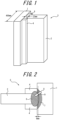
FIG. 1 is a schematic diagram illustrating a groove geometry in electroslag welding performed to evaluate the toughness of bond portion; and -
FIG. 2 is a schematic diagram illustrating a collection location of a Charpy impact test piece from the electroslag welded portion. - The following describes embodiments of the present disclosure. The following merely provides one of the preferred disclosed embodiments, and this disclosure is by no means limited to the following description. In this specification, the toughness of an unwelded steel plate itself is sometimes referred to as "toughness of base metal" to distinguish it from the toughness of bond portion after welding.
- A steel plate of this disclosure and a steel material used for producing the steel plate need to have the chemical composition described above. The following describes each of the components contained in the above chemical composition. Note that "%" indicating the content of each component is "mass%", unless otherwise stated.
- C is an element that has an effect of increasing the strength of the steel plate. When the C content is less than 0.010 %, the desired tensile strength cannot be achieved. The C content is therefore 0.010 % or more, preferably 0.020 % or more, and more preferably 0.030 % or more. On the other hand, when the C content exceeds 0.14 %, the formation of coarse martensite austenite constituent and cementite is promoted, resulting in a decrease in toughness of base metal and a significant degradation in toughness of the bond portion. The C content is therefore 0.14 % or less, preferably 0.10 % or less, and more preferably 0.08 % or less.
- Si is an element that functions as a deoxidizer and has an effect of increasing the strength of the steel plate. To achieve the effect, the Si content is 0.01 % or more. On the other hand, when the Si content exceeds 0.50 %, the formation of coarse martensite austenite constituent is promoted, and a decrease in toughness of base metal and toughness of the bond portion becomes apparent. The Si content is therefore 0.50 % or less, and preferably 0.35 % or less.
- Mn is an element that has an effect of increasing the strength of the steel plate. In addition, high strength, low yield ratio, and high toughness can be achieved by controlling a Mn concentration distribution as described below. When the Mn content is less than 0.9 %, the effect cannot be achieved. The Mn content is therefore 0.9 % or more, and preferably 1.2 % or more. On the other hand, when the Mn content exceeds 3.0 %, the area fraction of a Mn-enriched portion increases to form coarse MA, resulting in a decrease in toughness of base metal. In addition, the heat-affected zone hardens to significantly decrease the toughness of bond portion. The Mn content is therefore 3.0 % or less, and preferably 2.6 % or less.
- The chemical composition described here is an average composition of the steel plate. Therefore, the above Mn content is used as the "average Mn content" in the specification of the Mn concentration distribution described below.
- P is an element that degrades the toughness of base metal and the toughness of bond portion. Thus, the P content is desirably reduced as much as possible. When the P content exceeds 0.015 %, the toughness of base metal and the toughness of bond portion significantly decrease. This is thought to be due to the segregation of P in the Mn-enriched portion at high P content, resulting in hardening of the microstructure. The P content is therefore 0.015 % or less. On the other hand, no particular lower limit is placed on the P content, and the P content may be 0 %. Excessive reduction, however, leads to higher costs. Therefore, from the viewpoint of production cost, the P content is preferably 0.001 % or more.
- S is an element that degrades the toughness of base metal. Thus, the S content is desirably reduced as much as possible. When the S content is higher than 0.0050 %, the desired toughness of base metal and toughness of bond portion cannot be achieved. The S content is therefore 0.0050 % or less. On the other hand, no particular lower limit is placed on the S content, and the S content may be 0 %. Excessive reduction, however, leads to higher costs. Therefore, from the viewpoint of production cost, the S content is preferably 0.0003 % or more.
- Al is an element that acts as a deoxidizer. Al also fixes N in steel as AlN to contribute to the improvement in toughness of base metal. To achieve the effect, the Al content is 0.002 % or more, and preferably 0.010 % or more. On the other hand, when the Al content exceeds 0.080 %, the toughness of base metal decreases. The Al content is therefore 0.080 % or less, and preferably 0.060 % or less.
- Ti is an element that functions as a deoxidizer and contributes to the improvement in strength of the steel plate. Ti also combines with N to precipitate as TiN, a nitride that is stable even at high temperatures. Therefore, the pinning effect of TiN prevents austenite grain coarsening when heated, resulting in an improvement in toughness of base metal and toughness of bond portion. To achieve the effect, the Ti content is 0.003 % or more, and preferably 0.005 % or more. On the other hand, when the Ti content exceeds 0.030 %, the toughness of base metal and the toughness of bond portion deteriorate. The Ti content is therefore 0.030 % or less, preferably 0.025 % or less, and more preferably 0.020 % or less.
- N combines with Al or Ti to precipitate a nitride. The nitride inhibits the coarsening of austenite grains to improve the toughness of base metal and bond portion. To achieve the effect, the N content is 0.0015 % or more, and preferably 0.0025 % or more. On the other hand, when the N content exceeds 0.0080 %, the toughness of base metal and bond portion are rather reduced due to the increase in solute N content. The N content is therefore 0.0080 % or less, preferably 0.0065 % or less, and more preferably 0.0060 % or less.
- The chemical composition according to one of the embodiments can contain the above elements, with the balance being Fe and inevitable impurities. However, there is no intention in this expression of precluding the inclusion of other trace elements, without impairing the action or effect of this disclosure. Examples of the inevitable impurities include oxygen (O). The content of oxygen contained as inevitable impurities is preferably 0.0030 % or less.
- In the steel plate of this disclosure, excellent mechanical properties are achieved by forming a specific Mn concentration distribution, as described below. To achieve the Mn concentration distribution, the value of "4.83C + Mn" determined from the C content and the Mn content in the above chemical composition needs to be 1.4 mass% or more. The reason for this is described below.
- To form the Mn concentration distribution in a steel plate to be finally obtained, it is necessary to create microscopic variations in Mn concentration inside the steel plate during the process of producing the steel plate. To create the variations, it is necessary to set 4.83C + Mn to 1.4 mass% or more and control heating conditions in a reheating step as described below. Reheating a steel sheet with 4.83C + Mn of 1.4 mass% or more under specific conditions can promote the distribution of Mn into the reverse transformation austenite to form microscopic variations in Mn concentration. When the value of 4.83C + Mn is less than 1.4 mass%, the desired Mn concentration distribution cannot be achieved due to insufficient distribution of Mn into the reverse transformation austenite. As a result, the strength of the steel plate decreases to increase the yield ratio. Therefore, 4.83C + Mn is 1.4 mass% or more, and preferably 1.7 mass% or more. On the other hand, when 4.83C + Mn exceeds 3.3 mass%, the effect is saturated. Therefore, 4.83C + Mn is 3.3 mass% or less.
- TiN has a pinning effect that suppresses austenite grain growth in the heat-affected zone and improves the toughness of bond portion. When Ti/N is less than 2.0, the amount of TiN necessary to achieve the effect cannot be secured to deteriorate the toughness of bond portion. Therefore, Ti/N is 2.0 or more, and preferably 2.4 or more. On the other hand, when Ti/N exceeds 4.3, the toughness of base metal and the toughness of bond portion deteriorate due to the formation of TiC particles and the coarsening of TiN. Therefore, Ti/N is 4.3 or less, and preferably 4.0 or less.
- When PCM defined by the following formula (1) is higher than 0.30 mass%, good toughness of bond portion cannot be achieved. Therefore, PCM is 0.30 mass% or less, preferably 0.28 mass% or less, and more preferably 0.26 mass% or less:
Pcm = [C] + [Si]/30 + [Mn]/20 + [Cu]/20 + [Ni]/60 + [Cr]/20 + [Mo]/15 + [V]/10 + 5[B] - On the other hand, no particular lower limit is placed on PCM. However, an excessively low PCM reduces the strength of the steel plate. Therefore, PCM is preferably 0.15 mass% or more, more preferably 0.17 mass% or more, and further preferably 0.19 mass% or more.
- In other disclosed embodiments, the above chemical composition can optionally further contain at least one selected from the group consisting of Cu, Ni, Cr, Mo, W, Nb, V, B, Ca, REM, Mg, and Zr.
- Cu is an element that further improves the strength while maintaining the high toughness of the steel plate and can be optionally contained depending on the strength required. However, when the Cu content exceeds 3.0 %, hot brittleness occurs to deteriorate the surface characteristics of the steel plate. Therefore, when Cu is contained, the Cu content is 3.0 % or less. The Cu content is preferably 2.0 % or less. On the other hand, no particular lower limit is placed on the Cu content. However, to sufficiently achieve the effect, the Cu content is preferably 0.01 % or more, and more preferably 0.05 % or more.
- Like Cu, Ni is an element that further improves the strength while maintaining the high toughness of the steel plate and can be optionally contained depending on the strength required. However, when the Ni content exceeds 3.0 %, the effect of addition is saturated, which is economically disadvantageous. Therefore, when Ni is contained, the Ni content is 3.0 % or less. The N content is preferably 2.0 % or less. On the other hand, no particular lower limit is placed on the Ni content. However, to sufficiently achieve the effect, the Ni content is preferably 0.01 % or more, and more preferably 0.10 % or more.
- Cr is an element that further improves the strength of the steel plate and can be optionally contained depending on the strength required. However, when the Cr content exceeds 3.0 %, the toughness of the base metal and the bond portion deteriorates. Therefore, when Cr is contained, the Cr content is 3.0 % or less. The Cr content is preferably 2.0 % or less. On the other hand, no particular lower limit is placed on the Cr content. However, in terms of sufficiently achieving the strength improving effect by Cr, the Cr content is preferably 0.01 % or more, and more preferably 0.10 % or more.
- Like Cr, Mo is an element that further improves the strength of the steel plate and can be optionally contained depending on the strength required. However, when the Mo content exceeds 1.5 %, the toughness of the base metal and the bond portion deteriorates. In addition, quench cracks are more likely to occur during the process of producing the steel plate, resulting in reduced manufacturability. Therefore, when Mo is contained, the Mo content is 1.5 % or less, and preferably 1.0 % or less. On the other hand, no particular lower limit is placed on the Mo content. However, in terms of sufficiently achieving the strength improving effect by Mo, the Mo content is preferably 0.01 % or more, and more preferably 0.10 % or more.
- Like Cr and Mo, W is an element that further improves the strength of the steel plate and can be optionally contained depending on the strength required. However, when the W content exceeds 3.0 %, the toughness of the base metal and the bond portion deteriorates. Therefore, when W is contained, the W content is 3.0 % or less, and preferably 2.0 % or less. On the other hand, no particular lower limit is placed on the W content. However, in terms of sufficiently achieving the strength improving effect by W, the W content is preferably 0.01 % or more, and more preferably 0.10 % or more.
- Like Cr, Mo, and W, Nb is an element that further improves the strength of the steel plate and can be optionally contained depending on the strength required. However, when the Nb content exceeds 0.10 %, the toughness of the base metal and the bond portion decreases. Therefore, when Nb is contained, the Nb content is 0.10 % or less, and preferably 0.05 % or less. On the other hand, no particular lower limit is placed on the Nb content. However, in terms of sufficiently achieving the strength improving effect by Nb, the Nb content is preferably 0.005 % or more.
- Like Cr, Mo, W, and Nb, V is an element that further improves the strength of the steel plate and can be optionally contained depending on the strength required. However, when the V content exceeds 0.10 %, the toughness of the base metal and the bond portion decreases. Therefore, when V is contained, the V content is 0.10 % or less, and preferably 0.05 % or less. On the other hand, no particular lower limit is placed on the V content. However, in terms of sufficiently achieving the strength improving effect by V, the V content is preferably 0.005 % or more.
- B is an element that has an action of further increasing the strength of the steel plate by improving the quench hardenability. B also has an effect of further improving the toughness of bond portion by sticking solute nitrogen as a nitride in the heat-affected zone during large-heat input welding. However, when the B content exceeds 0.0050 %, the quench hardenability is excessively high, and the toughness of the base metal and the bond portion is rather reduced. Therefore, when B is contained, the B content is 0.0050 % or less, and preferably 0.0020 % or less. On the other hand, no particular lower limit is placed on the B content. However, in terms of sufficiently achieving the effect of addition of B, the B content is preferably 0.0003 % or more.
- Ca is an element that has an effect of further improving the toughness of base metal by refinement of crystal grains and can be optionally contained depending on the toughness of base metal required. However, when the Ca content exceeds 0.005 %, the effect of addition is saturated. Therefore, when Ca is contained, the Ca content is 0.005 % or less. On the other hand, no particular lower limit is placed on the Ca content. However, in terms of sufficiently achieving the toughness improving effect by Ca, the Ca content is preferably 0.001 % or more.
- Like Ca, REM (rare earth metal) is an element that has an effect of further improving the toughness of base metal by refinement of crystal grains and can be optionally contained depending on the toughness of base metal required. However, when the REM content exceeds 0.020 %, the effect of addition is saturated. Therefore, when REM is contained, the REM content is 0.020 % or less. On the other hand, no particular lower limit is placed on the REM content. However, in terms of sufficiently achieving the toughness improving effect by REM, the REM content is preferably 0.002 % or more.
- Like Ca and REM, Mg is an element that has an effect of further improving the toughness of base metal by refinement of crystal grains and can be optionally contained depending on the toughness of base metal required. However, when the Mg content exceeds 0.005 %, the effect of addition is saturated. Therefore, when Mg is contained, the Mg content is 0.005 % or less. On the other hand, no particular lower limit is placed on the Mg content. However, in terms of sufficiently achieving the toughness improving effect by Mg, the Mg content is preferably 0.001 % or more.
- Like Ca, REM, and Mg, Zr is an element that has an effect of further improving the toughness of base metal by refinement of crystal grains and can be optionally contained depending on the toughness of base metal required. However, when the Zr content exceeds 0.020 %, the effect of addition is saturated. Therefore, when Zr is contained, the Zr content is 0.020 % or less. On the other hand, no particular lower limit is placed on the Zr content. However, in terms of sufficiently achieving the toughness improving effect by Zr, the Zr content is preferably 0.002 % or more.
- The steel plate of this disclosure has a microstructure that contains bainite and martensite austenite constituent, with an area fraction of bainite of 80.0 % or more. The reason for limiting the microstructure to the above range is described below. The term "area fraction" in the following description refers to an area fraction relative to the whole microstructure, unless otherwise specified. The above microstructure refers to a microstructure at a 1/4 thickness position of the steel plate.
- Bainite is a microstructure necessary to improve the strength and toughness of the steel plate, as described below. On the other hand, martensite austenite constituent (MA) is an even harder microstructure than bainite because of its C enrichment. Therefore, forming MA can improve the tensile strength. In addition, a large amount of mobile dislocation is introduced around MA, which suppresses the increase in yield stress. Therefore, to achieve both high strength and low yield ratio, the microstructure needs to contain bainite and martensite austenite constituent.
- When the area fraction of bainite is less than 80.0 %, sufficient strength and toughness of base metal cannot be achieved. Therefore, the area fraction of bainite is 80.0 % or more, preferably 85.0 % or more, and more preferably 90.0 % or more. On the other hand, no particular upper limit is placed on the area fraction of bainite. However, when the area fraction of bainite is excessively high, the area fraction of martensite austenite constituent is relatively low, making it difficult to sufficiently reduce the yield ratio. Therefore, the area fraction of bainite is preferably 99.0 % or less. The area fraction of bainite can be measured by the method described in Examples.
- As a result of the inventors' investigation, it was found that even with MA in the base metal, the toughness of bond portion decreases when the area fraction is 5.0 % or more. This is thought to be because of the following reasons. That is, since the bond portion is heated to a high temperature close to the melting point during welding, MA contained in the steel plate is once decomposed by the heating. However, during the cooling process after welding, MA is regenerated in the bond portion. The amount of MA regenerated in this process increases with the amount of MA contained in the steel plate prior to welding. When the amount of MA regenerated in the bond portion is high, the toughness of bond portion decreases. Therefore, in this disclosure, the area fraction of martensite austenite constituent in the microstructure of the steel plate is less than 5.0 %, preferably 4.9 % or less, more preferably 4.7 % or less, and further preferably 4.5 % or less, in order to improve the toughness of bond portion.
- On the other hand, no particular lower limit is placed on the area fraction of MA. However, as described above, MA has an effect of improving the tensile strength and an effect of suppressing the increase in yield stress. From the viewpoint of sufficiently providing these effects, the area fraction of MA in the above microstructure is preferably 1.0 % or more, and more preferably 2.0 % or more.
- In PTL 3, since the desired mechanical properties are achieved by increasing the area fraction of MA, the area fraction of MA must be 5 % or more. In contrast, this disclosure achieves the desired mechanical properties by controlling the Mn concentration distribution, as described below. Therefore, excellent mechanical properties can be achieved even though the area fraction of MA is less than 5.0 %. The area fraction of MA in the base metal is low, less than 5.0 %, and the toughness of bond portion is thus superior to that of PTL 3. The difference between the steel plate of this disclosure and the steel plate disclosed in PTL 3 is clear also from this fact. Furthermore, there is no need to control MA generation through complex cooling control consisting of the first water-cooling step, air-cooling step, and second water-cooling step, as in PTL 3.
- No particular size is placed on MA. MA may have any size. However, when MA is excessively coarse, the toughness of the steel plate decreases. Therefore, from the viewpoint of further improving the toughness, the average equivalent circular diameter of MA is preferably 5.0 µm or less, and preferably 4.0 µm or less. On the other hand, no particular lower limit is placed on the average equivalent circular diameter of MA. However, the average equivalent circular diameter of MA usually may be 0.8 µm or more, or 1.0 µm or more.
- The area fraction and average equivalent circular diameter of MA can be determined by applying LePera corrosion (Journal of Metals, March, 1980, p. 38-39) to a steel sheet as a sample, observing the steel sheet using a scanning electron microscope (SEM) at a magnification of 1000×, and then analyzing captured images using image interpretation equipment.
- The microstructure according to one of the embodiments may consist of bainite and martensite austenite constituent. The microstructures according to other disclosed embodiments may also contain another structure, in addition to bainite and martensite austenite constituent. The other structure may be any structure without limitation. For example, the other structure may be at least one selected from the group consisting of ferrite, pearlite, martensite, or retained austenite. When the other structure is contained in the microstructure, the total area fraction of the other structure is preferably 19 % or less, more preferably 15 % or less, and further preferably 10 % or less.
- The steel plate according to one of the embodiments consists of, with area fraction:
- 80 % to 99.0 % of bainite;
- 1.0 % to 15.0 % of martensite austenite constituent; and a residual microstructure, and
- the residual microstructure may be at least one selected from the group consisting of ferrite, pearlite, martensite, or retained austenite.
- The inventors found that it is possible to intentionally form microscopic variations in Mn concentration inside the steel plate by controlling the C and Mn contents and the heating conditions in the reheating step after hot rolling. Then, it was found that by appropriately controlling the microscopic variations in Mn concentration, i.e., the Mn concentration distribution, a steel plate with high strength, low yield ratio, and high toughness can be obtained. This may be because the distribution and size of MA are affected by the Mn concentration distribution. For example, MA tends to be formed in a Mn-enriched region. As described above, MA has an effect of increasing the strength because it is a harder microstructure than bainite. In addition, MA has an action for decreasing the yield ratio through the introduction of mobile dislocation. Therefore, by controlling the Mn concentration distribution, the distribution of MA can be controlled, resulting in both high strength and low yield ratio.
- This disclosure is based on the above technical concept. Specifically, the steel plate of this disclosure has a Mn concentration distribution that satisfies the following conditions (1) to (3). The Mn concentration distribution in this disclosure refers to a Mn concentration distribution at a 1/4 thickness position of the steel plate:
- (1) Area fraction of average concentration region of Mn of less than 90 %;
- (2) Area fraction of Mn-enriched region of 1.0 % or more; and
- (3) Average equivalent circular diameter of Mn-enriched region of 7.0 µm or less.
- When the area fraction of the average concentration region of Mn is 90 % or more, the hard microstructure containing MA is insufficient to achieve the desired strength. In addition, the enrichment of Mn for the Mn-enriched region is insufficient, making the effect of yield stress reduction due to MA formation insufficient. As a result, the yield ratio is also likely to be high. Therefore, the area fraction of the average concentration region of Mn is less than 90 %, preferably 85 % or less, and more preferably 80 % or less. On the other hand, no particular lower limit is placed on the area fraction of the average concentration region of Mn. However, when the area fraction of the average concentration region of Mn is too low, the size of the Mn-enriched region increases, resulting in the coarsening of MA formed in the enriched region. Therefore, the area fraction of the average concentration region of Mn is preferably 50 % or more, and more preferably 60 % or more. The "average concentration region of Mn" is defined here as a region with a Mn concentration of 0.9 times to 1.1 times the average Mn content (mass%).
- When the area fraction of the Mn-enriched region is less than 1.0 %, the formation of MA is insufficient, and both high strength and low yield ratio cannot be achieved. Therefore, the area fraction of the Mn-enriched region is 1.0 % or more, preferably 1.5 % or more, more preferably 2.0 % or more, and further preferably 6.2 % or more. On the other hand, no particular upper limit is placed on the area fraction of the Mn-enriched region. However, when the area fraction of the Mn-enriched region is too high, the size of the enriched region increases, and the MA formed in the enriched region is likely to become coarse. Therefore, the area fraction of the Mn-enriched region is preferably less than 50 %, more preferably less than 40 %, and further preferably 20 % or less. The Mn-enriched region is eliminated by heating during welding. Thus, the existence of the enriched region does not adversely affect the toughness of bond portion after welding. Therefore, this disclosure can achieve both excellent mechanical properties of the steel plate and high toughness of bond portion.
- When the average equivalent circular diameter of the Mn-enriched region is larger than 7.0 µm, MA formed within the Mn-enriched region also becomes coarse, resulting in reduced toughness of the steel plate. Therefore, the average equivalent circular diameter of the Mn-enriched region is 7.0 µm or less, and preferably 4.0 µm or less. On the other hand, no particular lower limit is placed on the average equivalent circular diameter of the Mn-enriched region. However, the average equivalent circular diameter of the Mn-enriched region generally may be 1.0 µm or more, or 1.5 µm or more.
- The Mn concentration distribution can be measured using an electron probe microanalyzer (EPMA). Specifically, a test piece is taken from the steel plate so that the observation position is at a 1/4 thickness position. The Mn concentration distribution in the test piece is measured by the EPMA to calculate the area fraction of the average concentration region of Mn, the area fraction of the Mn-enriched region, and the average equivalent circular diameter of the Mn-enriched region. The measurement of the Mn concentration distribution by the EPMA is performed in two or more randomly selected fields of view, with the size of one field of view being 50 µm × 50 µm and 250 × 250 measurement points per field of view.
- The steel plate of this disclosure has a Charpy absorbed energy at 0 °C: vE0 of 70 J or more. The Charpy absorbed energy is one of the indices of toughness. The steel plate of this disclosure with vE0 of 70 J or more produces excellent seismic safety even when used in high-rise buildings. vE0 is preferably 80 J or more, and more preferably 100 J or more. On the other hand, a higher vE0 is better from the viewpoint of seismic resistance. Thus, no particular upper limit is placed on vE0. However, vE0 generally may be 250 J or less, 220 J or less, or 210 J or less.
- The Charpy absorbed energy at 0 °C of the above steel sheet can be measured in accordance with the provisions of JIS Z 2242 using a V-notch test piece taken from a 1/4 thickness position of the steel plate in accordance with the provisions of JIS Z 2202.
- No particular limitation is placed on the yield stress (YS) of the steel plate of this disclosure. However, from the viewpoint of increasing the strength associated with increased height in building structures, the yield stress is preferably 600 MPa or more, and preferably 620 MPa or more. No particular upper limit is also placed on the yield stress. However, the yield stress may be, for example, 900 MPa or less, 880 MPa or less, or 850 MPa or less.
- No particular limitation is placed on the tensile strength (TS) of the steel plate of this disclosure. However, from the viewpoint of increasing the strength associated with increased height in building structures, the tensile strength is preferably 780 MPa or more, and more preferably 800 MPa or more. No particular upper limit is also placed on the tensile strength. However, the tensile strength may be, for example, 1100 MPa or less, or 1000 MPa or less.
- No particular limitation is placed on the yield ratio (YR) of the steel plate of this disclosure. However, from the viewpoint of improving the deformation performance of building structures considering the allowable margin against fracture during earthquakes, the yield ratio is preferably 85 % or less. On the other hand, no lower limit is also placed on the yield ratio. However, the yield ratio may be, for example, 70 % or more, or 75 % or more. The yield ratio is here a value expressed as a percentage of the ratio of yield stress (YS) to tensile strength (TS), i.e., YS/TS × 100 (%).
- The above yield stress and tensile strength can be measured by a tensile test in accordance with JIS Z 2241, using a JIS No. 4 tensile test piece taken from a 1/4 thickness position of the steel plate. The yield ratio can be calculated from the yield stress and tensile strength measured by the above method.
- No particular limitation is placed on the toughness of bond portion of the steel plate of this disclosure. However, the Charpy absorbed energy at 0 °C (vE0) of the bond portion is preferably 47 J or more. No particular upper limit is also placed on vE0 in the bond portion. However, vE0 generally may be 150 J or less.
- vE0 in the bond portion is a value measured by producing a welded joint by electroslag welding with an amount of welding heat input of 40 kJ/mm or more and then using a JIS No. 4 Charpy impact test piece taken from the welded joint so that the notch position is at the bond portion. More specifically, vE0 in the bond portion can be measured by the method described in Examples.
- No particular limitation is placed on the plate thickness of the above steel plate. The plate thickness can be any thickness. The plate thickness of the steel plate is preferably 6 mm or more, more preferably 9 mm or more, and further preferably 12 mm or more. From the viewpoint of the response to increased height in building structures, the plate thickness is preferably 40 mm or more, and more preferably 60 mm or more. On the other hand, no particular upper limit is also placed on the plate thickness of the steel plate. However, the plate thickness is preferably 100 mm or less.
- The following describes a method of producing a steel plate according to one of the embodiments. The steel plate can be produced by applying the steps (a) to (d) sequentially to a steel material having the above-described chemical composition:
- (a) Hot rolling step;
- (b) First cooling step;
- (c) Reheating step; and
- (d) Second cooling step.
- Conditions in the respective steps are described in detail below. In the following description, unless otherwise specified, the temperature means a temperature at the center of the plate thickness (position of plate thickness × 1/2). The temperature at the center of the plate thickness can be determined by heat transfer calculation from the surface temperature of the steel plate measured by a radiation thermometer. The temperatures under the heating conditions and cooling conditions after the hot rolling step are temperatures at a 1/4 thickness position. The heating rate and the cooling rate also mean an average heating rate and an average cooling rate calculated based on the temperatures at the 1/4 thickness position, respectively.
- Any form of material can be used as the above steel material. The steel material may be, for example, steel slab. No particular limitation is placed on the method of producing the steel material. However, the steel material can be produced, for example, by melting and casting steel having the above-described chemical composition. The melting can be performed by any method using a converter, an electric furnace, an induction furnace, or the like. The casting is preferably performed by continuous casting in terms of productivity, but also can be performed by ingot casting and blooming.
- In the hot rolling step, the above steel material is hot rolled to form a steel plate. No particular limitation is placed on the conditions of the hot rolling. The hot rolling can be performed under any conditions. Typically, the steel material is heated to a specific heating temperature and then rolled. The heating may be performed after the steel material obtained by a method such as casting is once cooled. Alternatively, the obtained steel material may be directly subjected to the heating without cooling it.
- In this disclosure, the microstructure and properties of the steel plate are controlled in the reheating step and the second cooling step after the hot rolling. Therefore, no particular limitation is placed on the heating temperature in the hot rolling step. The heating temperature can be any temperature. However, when the heating temperature is less than 1000 °C, the load on the rolling mill during hot rolling may increase due to the high deformation resistance of the steel material, making it difficult to perform hot rolling. Therefore, the heating temperature is preferably 1000 °C or more. On the other hand, when the heating temperature is higher than 1250 °C, oxidation of the steel is more pronounced, resulting in increased loss due to oxidation and lower yield rate. Therefore, the heating temperature is preferably 1250 °C or less.
- No particular limitation is placed on a rolling finish temperature. However, the rolling finish temperature is preferably 1000 °C or less. The rolling finish temperature is preferably 750 °C or more.
- Next, the steel plate obtained in the above hot rolling step is cooled (first cooling step). In this disclosure, cooling in this first cooling step can be performed under any conditions without any particular limitations in order to control the microstructure and properties of the steel plate in the subsequent reheating step and second cooling step. However, because it is necessary to control the average heating rate in the temperature range from Ac1 point to Ac3 point in the subsequent reheating step, a cooling stop temperature in the first cooling step may be Ac1 point or less. The cooling stop temperature is preferably 500 °C or less. When the cooling stop temperature is 500 °C or less, coarsening of precipitates can be suppressed, and the Mn-enriched region can be generated more uniformly. As a result, the strength and toughness of the steel plate can be further improved, and the yield ratio can be further reduced. The cooling stop temperature is more preferably 250 °C or less. On the other hand, no lower limit is also placed on the cooling stop temperature. The steel plate can be cooled to any temperature. However, since excessive cooling reduces the productivity, the cooling stop temperature is preferably 0 °C or more, more preferably 10 °C or more, and further preferably 20 °C or more. Typically, the cooling stop temperature is preferably the room temperature or more.
- The cooling in the first cooling step can be performed by any method with no particular limitation. For example, the cooling can be performed by one or both of air cooling and water cooling. From the viewpoint of further improving the strength and toughness of the steel plate, the cooling is preferably performed by water cooling. The water cooling is more preferably performed by at least one selected from the group consisting of spray cooling, mist cooling, or laminar cooling.
- Next, the steel plate after the first cooling step is heated to a reheating temperature in a specific heating pattern and held at the reheating temperature.
- Average heating rate in temperature range from Ac 1 point to Ac3 point: 2.0 °C/s or less
- During the heating process, Mn is distributed into austenite formed by reverse transformation from bainite and martensite through the temperature range from Ac1 point or more to Ac3 point or less (two-phase region), resulting in microscopic variations in Mn concentration. However, when the average heating rate in the temperature range from Ac1 point to Ac3 point is higher than 2.0 °C/s, Mn distribution does not sufficiently progress. As a result, the desired Mn concentration distribution cannot be achieved. Therefore, in the reheating step, the steel plate after the first cooling step is heated at the average heating rate in the temperature range from Ac1 point to Ac3 point at the 1/4 thickness position: 2.0 °C/s or less. On the other hand, no particular lower limit is placed on the average heating rate. However, when the heating rate is excessively slow, the effect of controlling the heating rate is saturated, and the time required for heating increases, resulting in reduced productivity. Therefore, the average heating rate is preferably 0.01 °C/s or more.
- Stay time in temperature range from Ac3 point - 100 °C to Ac3 point: 60 seconds or more
- Similarly, when a stay time in the temperature range from Ac3 point - 100 °C to Ac3 point is less than 60 seconds, Mn distribution does not sufficiently progress. As a result, the desired Mn concentration distribution cannot be achieved. Therefore, during the heating process in the reheating step, the stay time in the temperature range from Ac3 point - 100 °C to Ac3 point is 60 seconds or more. On the other hand, an excessively long stay time reduces productivity. Therefore, the stay time is preferably 60 minutes or less.
- The heating pattern in the above heating process just has to satisfy the above conditions, and no particular limitation is placed on the other conditions. For example, the temperature may be continuously raised to the reheating temperature or intentionally kept in the two-phase region.
- Ac1 point and Ac3 point are determined by formulas (2) and (3) below:
Ac1 (°C) = 751 - 26.6C + 17.6Si - 11.6Mn - 169Al - 23Cu - 23Ni + 24.1Cr + 22.5Mo + 233Nb - 39.7V - 5.7Ti - 895B Ac3 (°C) = 937 - 476.5C + 56Si - 19.7Mn - 16.3Cu - 4.9Cr - 26.6Ni + 38.1Mo + 124.8V + 136.3Ti + 198Al + 3315B - In the above reheating step, the steel plate is heated to a reheating temperature of Ac3 point or more and Ac3 point + 60 °C or less. As a result, the structures such as bainite and martensite contained in the steel plate at the completion of the first cooling step undergo reverse transformation to austenite, resulting in microstructure consisting of an austenite single phase.
- When the reheating temperature is less than Ac3 point, a soft recovered microstructure is formed in the microstructure to decrease the strength of the base metal. In addition, coarse MA is formed in the Mn-enriched region to decrease the toughness of the base metal. Therefore, the reheating temperature is Ac3 point or more. On the other hand, when the reheating temperature is higher than Ac3 point + 60 °C, austenite crystal grains coarsen, and homogenization of the composition progresses. As a result, the desired Mn concentration distribution cannot be achieved. Therefore, the reheating temperature is Ac3 point + 60 °C or less, more preferably Ac3 point + 55 °C or less, and further preferably Ac3 point + 50 °C or less.
- In the above reheating step, the steel plate is heated up to the above reheating temperature and then held at the re-heating temperature for a specific holding time. When the holding time is less than 10 minutes, the average equivalent circular diameter of the Mn-enriched region in the steel plate to be finally obtained cannot be 7.0 µm or less. This may be due to the short holding time, which increased the variation in grain size of the reverse transformation austenite, resulting in a non-uniformity in size of the Mn-enriched region. Therefore, the holding time is 10 minutes or more. On the other hand, no particular upper limit is placed on the holding time. However, the holding time is preferably 100 minutes or less, as excessive long holding time reduces productivity.
- In the reheating step, any heating method can be used. An example of the heating method is furnace heating. For the furnace heating, a general heat treatment furnace can be used without any particular limitations.
- Next, the steel plate after the reheating step is cooled. Specifically, the steel plate after the reheating step is subjected to accelerated cooling to an accelerated cooling stop temperature of 100 °C to 600 °C at an average cooling rate at the 1/4 thickness position: 1.0 °C/s to 200.0 °C/s, and then air cooled to a temperature of 100 °C or less.
- Accelerated cooling under the above conditions can transform reverse transformation austenite to bainite to obtain a bainite-dominated microstructure. When the average cooling rate is less than 1.0 °C/s, ferrite is formed, and the area fraction of bainite thus cannot be 80.0 % or more. Therefore, the average cooling rate is 1.0 °C/s or more, and preferably 5.0 °C/s or more. On the other hand, when the average cooling rate is higher than 200.0 °C/s, it is difficult to control the temperature at each position in the steel plate, which leads to material property variations in the plate transverse direction and rolling direction, resulting in material variations such as strength properties. Therefore, the average cooling rate is 200 °C/s or less, preferably 150.0 °C/s or less, and more preferably 100.0 °C/s or less.
- No particular limitation is placed on the method of the accelerated cooling. Any method can be performed for cooling. Typically, the accelerated cooling is preferably performed by one or both of air cooling and water cooling, and water cooling is more preferred. Any water-based method (e.g., spray cooling, mist cooling, laminar cooling, etc.) can be used for the water cooling. Mist cooling is preferably used as the method of the water cooling.
- In the above second cooling step, accelerated cooling is performed to the accelerated cooling stop temperature from 100 °C to 600 °C, followed by air cooling. When the accelerated cooling stop temperature is less than 100 °C, all austenite undergoes bainite transformation. Thus, the microstructure containing martensite austenite constituent cannot be obtained. In addition, the tempering effect cannot be achieved, resulting in reduce toughness of the steel plate. Therefore, the accelerated cooling stop temperature is 100 °C or more, and preferably 200 °C or more. On the other hand, when the accelerated cooling stop temperature is higher than 600 °C, ferrite is likely to be formed. Thus, the area fraction of bainite cannot be 80.0 % or more. Therefore, the accelerated cooling stop temperature is 600 °C or less, and preferably 500 °C or less.
- After the accelerated cooling is stopped, the steel plate is further air cooled to a temperature of 100 °C or less. The air cooling may be allowed to naturally cool, i.e., natural cooling, rather than forced cooling. In the air cooling, the steel plate may be cooled to the temperature of 100 °C or less, but it is not necessary to stop air cooling at a specific temperature. The steel plate usually may be air cooled to the room temperature (ambient temperature).
- Other conditions in the air cooling are not particularly limited, as they do not substantially affect the microstructure, etc. of the steel plate. For example, no particular limitation is placed on the cooling rate in the air cooling. Cooling may be performed at any rate. Typically, the cooling rate in the air cooling may be less than 1.0 °C/s, or 0.5 °C/s or less. No particular lower limit is also placed on the cooling rate in the air cooling. However, the cooling rate may be 0.001 °C/s or more, 0.01 °C/s or more, or 0.07 °C/s or more.
- Similarly, no particular limitation is also placed on the time required for the air cooling (air cooling time). In this embodiment, there is no need to perform any special treatment after the air cooling, so there is no problem with time-consuming air cooling. Typically, the air cooling time may be more than 300 s, 310 s or more, or 320 s or more. On the other hand, no particular upper limit is also placed on the air cooling time. However, the air cooling time may be, for example, 24 hours or less, or 12 hours or less. The time taken from the start of air cooling to reach 100 °C is defined here as the air cooling time, in the second cooling step.
- As described above, the steel plate of this disclosure can be produced by controlling the chemical composition, in particular, the C and Mn contents, within specific ranges and by appropriately controlling the heating conditions in the reheating step after hot rolling. Therefore, the steel plate of this disclosure is easier to produce and more suitable for industrial production, compared with the steel plate in PTL 3, which requires controlling the conditions during the cooling process after reheating to control the formation of MA.
- In this disclosure, microscopic variations in Mn concentration are intentionally created by controlling the heating conditions in the reheating step as described above. As a result, the steel plate to be finally obtained has the above-described Mn concentration distribution. In contrast, PTL 3 does not control the heating conditions to create microscopic variations in Mn concentration as in this disclosure. Therefore, the production process described in PTL 3 cannot obtain a steel plate with the Mn concentration distribution that satisfies the conditions of this disclosure. MA is present in the steel plate in PTL 3. However, the Mn concentration around this MA is the same average concentration as the Mn concentration in the matrix. Thus, it is thought that there are no enriched regions that satisfy the conditions of this disclosure.
- In another disclosed embodiment, further heat treatment can be performed after the first cooling step and before the reheating step, for higher strength and lower yield ratio of the steel plate. That is, in the embodiment, a steel plate can be produced by sequentially applying the steps (a) to (e) to a steel material having the above-described chemical composition:
- (a) Hot rolling step;
- (b) First cooling step;
- (c) Heat treatment step;
- (d) Reheating step; and
- (e) Second cooling step.
- In the above heat treatment step, the steel plate after the first cooling step is heated to a heat treatment temperature of Ac3 point or more and 1050 °C or less, held at the heat treatment temperature for a holding time of 5 minutes or more, and then cooled to a cooling stop temperature of 500 °C or less. The heat treatment can achieve both high strength and low yield ratio at an even higher level. The reason for this may be as follows. The reheating step after the heat treatment step homogenizes the present position of the Mn-enriched portion to increase the frequency of formation of the reverse transformation nucleation site. As a result, the formation of microscopic variations in Mn concentration is promoted to increase the final area fraction of the Mn-enriched region. Specifically, the area fraction of the enriched region can be 6.2 % or more. As described above, MA is formed in the Mn-enriched region, leading to both high strength and low yield ratio.
- By setting the heat treatment temperature to Ac3 point or more and 1050 °C or less, desired bainite and martensitic microstructure can be obtained by ensuring quench hardenability. When the heat treatment temperature is less than Ac3 point, the desired toughness of base metal cannot be achieved. This is thought to be due to the formation of coarse ferrite during heat treatment, resulting in the formation of an upper bainitic microstructure with coarse carbides in the finally obtained microstructure. On the other hand, the desired toughness of base metal cannot be achieved also when the heat treatment temperature is higher than 1050 °C. This is thought to be due to the formation of coarse bainite and coarse martensite during heat treatment, resulting in the formation of a coarse bainitic microstructure in the finally obtained microstructure.
- The holding time at the heat treatment temperature is 5 minutes or more, and preferably 10 minutes or more, to reduce the variation in austenite grain size. On the other hand, no particular upper limit is placed on the holding time. However, considering productivity, the holding time is preferably 100 minutes or less, and more preferably 60 minutes or less, as the effect will be saturated even if the holding time is excessively long.
- Any heating method can be used for heating in the heat treatment step, as long as the heat treatment temperature and the holding time can be controlled as described above. An example of the heating method that can be used is furnace heating. For the furnace heating, a general heat treatment furnace can be used without any particular limitations.
- After holding the steel plate at the above heat treatment temperature, the steel plate is cooled down to the cooling stop temperature of 500 °C or less. The austenite formed in the heat treatment step is transformed to a low temperature transformation phase of bainite and martensite by the cooling, and the subsequent reheating step can achieve further high strength and low yield ratio. When the cooling stop temperature is higher than 500 °C, the desired strength and toughness cannot be ensured. Therefore, the cooling stop temperature is 500 °C or less, preferably 400 °C or less, and more preferably 200 °C or less. On the other hand, no particular lower limit is placed on the cooling stop temperature. However, since excessive cooling reduces the productivity, the cooling stop temperature is preferably 0 °C or more, more preferably 10 °C or more, and further preferably 20 °C or more. Typically, the cooling stop temperature is preferably the room temperature or more.
- No particular limitation is placed on the method of performing the cooling. The cooling can be performed by any method such as air cooling or water cooling. Any water-based method can be used for the water cooling, such as spray cooling, mist cooling, or laminar cooling.
- When the above heat treatment step is performed, the steel plate after cooling may be subjected to the next reheating step. When the above heat treatment step is not performed, the steel plate after the first cooling step may be subjected to the next reheating step without heat treatment.
- In another disclosed embodiment, a further tempering step can be optionally applied after the reheating step, such as for the purpose of correcting the shape of the steel plate. A lower cooling stop temperature in the cooling step after reheating can be expected to further improve the toughness of the base metal due to the effect of tempering. When tempering is performed, the heating temperature is preferably 200 °C to 500 °C. Cooling of the steel sheet after the above tempering step can be performed by any method, since the cooling rate does not change the material properties.
- Steel plates were produced according to the following procedure, and their properties were evaluated.
- First, molten steel having each chemical composition presented in Table 1 was melted in a converter and made into a steel slab (thickness: 260 mm) as a steel material by continuous casting. PCM (mass%) determined by formula (1) above, Ac1 point (°C) determined by formula (2), and Ac3 point (°C) determined by formula (3) are listed in Table 1.
- Each steel slab was heated to 1150 °C and then hot rolled to be a steel plate with the thickness presented in Tables 2 and 3 (hot rolling step). The rolling finish temperature in the hot rolling is presented in Tables 2 and 3.
- The obtained steel plate was cooled to the cooling stop temperature presented in Tables 2 and 3 by the cooling method presented in Tables 2 and 3 (first cooling step).
- Next, the steel plate after the first cooling step was reheated under the conditions presented in Tables 2 and 3 (reheating step). However, in some examples, the steel plate after the first cooling step was subjected to heat treatment under the conditions presented in Tables 2 and 3 (heat treatment step) and then reheated. The reheating was performed using a heat treatment furnace.
- Finally, after the reheating, the steel plate was subjected to accelerated cooling under the conditions presented in Tables 2 and 3. After the accelerated cooling was stopped, the steel plate was air cooled (allowed to be naturally cooled) to the room temperature. The accelerated cooling was performed by water cooling. The air cooling time (time taken to reach 100 °C) in the air cooling was 1 hour or more.
- The microstructure, Mn concentration distribution, mechanical properties, and post-weld toughness of bond portion were evaluated for each of the steel plates obtained as described above. The evaluations were conducted in the methods described below.
- From each steel plate, a test piece for microstructure observation was taken so that the observation position was at a 1/4 thickness position. The test piece was embedded in resin so that the cross-section perpendicular to the rolling direction is the observation plane, and then mirror-polished. Next, the observation plane was subjected to LePera corrosion and then observed using a scanning electron microscope at a magnification of 1000× to capture images of the microstructure, thus identifying the martensite austenite constituent microstructure. The captured images of the five fields of view were analyzed by an image interpretation device to determine the area fraction and average equivalent circular diameter of the martensite austenite constituent microstructure.
- In addition, from each steel plate, a test piece for microstructure observation was taken so that the observation position was at a 1/4 thickness position. The test piece was embedded in resin so that the cross-section perpendicular to the rolling direction is the observation plane, and then mirror-polished. Next, the observation plane was subjected to nital etching and then observed using a scanning electron microscope at a magnification of 200× to capture images of the microstructure, thus identifying the bainitic microstructure. The captured images of the five fields of view were analyzed by an image interpretation device to determine the area fraction of the bainitic microstructure.
- From each steel plate, a test piece was taken so that the observation position was at a 1/4 thickness position. The Mn concentration distribution in the test piece was measured by EPMA to calculate the area fraction of the average concentration region of Mn, the area fraction of the Mn-enriched region, and the average equivalent circular diameter of the Mn-enriched region. The measurement of the Mn concentration distribution by EPMA was performed in two or more randomly selected fields of view, with the size of one field of view being 50 µm × 50 µm and 250 × 250 measurement points per field of view.
- A JIS No. 4 tensile test piece was taken from a 1/4 thickness position of each steel plate. Using the tensile test piece, tensile test was performed in accordance with the provisions of JIS Z 2241 to measure the yield stress, tensile strength, and yield ratio of the steel plate. In addition, a V-notch test piece was taken from a 1/4 thickness position of each steel plate in accordance with the provisions of JIS Z 2202. Using the V-notch test piece, the Charpy absorption energy (vE0) was determined by Charpy impact test at 0 °C in accordance with the provisions of JIS Z 2242 to evaluate the toughness of base metal.
- To evaluate the toughness in the heat-affected zone of each steel plate, a welded joint was prepared by the following procedure, and the Charpy absorbed energy at the bond portion was measured.
- First, from each steel plate, a pair of test plates for joint, each having the same plate thickness as the steel plate, was taken. Using one of the test plates for joint as a skin plate 1 and the other as a
diaphragm 2, a groove 3 with the geometry illustrated inFIG. 1 was prepared. Electroslag welding was then performed with an amount of welding heat input of 40 kJ/mm or more to produce a welded joint 5. - Next, as illustrated in
FIG. 2 , a JIS No. 4 Charpy impact test piece 8 was taken from the welded joint 5 so that the position of anotch 9 was at the bond portion. The position of thenotch 9 was the intersection of the weld line and a straight line passing aposition 6 mm apart from the surface of the skin plate 1. The Charpy impact test piece 8 was taken so that the longitudinal direction of the test piece was perpendicular to the weld line. - The Charpy test piece was used to measure the absorbed energy (vE0) at the bond portion at the welded joint in the Charpy impact test at 0 °C. For some steel plates whose base metal properties did not meet the target, the evaluation of the toughness of bond portion was not conducted.
- The obtained results are presented in Tables 4 and 5. The followings were considered acceptable: yield stress of 600 MPa or more, tensile strength of 780 MPa or more, yield ratio of 85 % or less, absorbed energy at 0 °C (vE0) of 70 J or more, and absorbed energy at 0 °C (vE0) at the bond portion at the welded joint of 47 J or more.
- All of the steel plates satisfying the conditions of this disclosure had high strength and low yield ratio as well as excellent toughness of base metal, each having a yield stress of 600 MPa or more, a tensile strength of 780 MPa or more, a yield ratio (YR) of 85 % or less, and an absorbed energy at 0 °C vE0 of 70 J or more. Even when large-heat input welding with an amount of welding heat input exceeding 40 kJ/mm was applied, vE0 at the bond portion at the welded joint was 47 J or more, having excellent toughness of bond portion at the welded joint. On the other hand, for the steel plates that did not satisfy the conditions of this disclosure, at least one of the following properties was inferior: base metal strength, yield ratio, toughness of base metal, and toughness of the bond portion at the welded joint.
-
Table 1 Steel sample ID Chemical composition (mass%)* 4.83C + Mn (mass%) Ti/N PCM (mass%) Ac1 (°C) Ac3 (°C) Remarks C Si Mn P S Al Ti N Others A 0.052 0.11 2.5 0.003 0.0010 0.035 0.012 0.0035 - 2.8 3.43 0.181 717 878 Disclosed steel B 0.022 0.21 2.6 0.004 0.0008 0.032 0.011 0.0040 Ni: 2.3, Ca: 0.001 2.7 2.75 0.197 666 834 Disclosed steel C 0.046 0.15 2.3 0.003 0.0009 0.010 0.021 0.0065 Cu: 1.2, REM: 0.0020 2.5 3.23 0.226 696 863 Disclosed steel D 0.047 0.02 1.5 0.014 0.0022 0.037 0.014 0.0050 Cr: 2.1, B: 0.0020 1.7 2.80 0.238 775 892 Disclosed steel E 0.049 0.16 1.8 0.002 0.0009 0.042 0.006 0.0027 Cu: 1.2, Ni: 2.5, B: 0.0012 2.0 2.22 0.252 638 814 Disclosed steel F 0.044 0.14 1.7 0.010 0.0020 0.030 0.014 0.0035 Ni: 0.8, Mo: 0.5, Nb: 0.01, V: 0.040, B: 0.0005 1.9 4.00 0.187 721 902 Disclosed steel G 0.096 0.02 1.2 0.001 0.0010 0.005 0.017 0.0055 Cu: 1.2, Cr: 0.6, W: 0.5 1.7 3.09 0.247 721 850 Disclosed steel H 0.035 0.06 2.1 0.005 0.0012 0.041 0.016 0.0039 Cu: 0.6, Ni: 1.3, Cr: 1.7, B: 0.0013, Ca: 0.0020 2.3 4.10 0.285 716 844 Disclosed steel I 0.030 0.34 2.6 0.004 0.0040 0.043 0.015 0.0040 Ni: 1.6, Nb: 0.028, B: 0.0009, REM: 0.0030 2.7 3.75 0.203 688 861 Disclosed steel J 0.042 0.20 1.6 0.005 0.0010 0.045 0.014 0.0034 Ni: 1.4, Cr: 0.7, Mo: 0.6, Mg: 0.002 1.8 4.12 0.227 725 890 Disclosed steel K 0.061 0.10 1.3 0.002 0.0009 0.040 0.015 0.0043 Cr: 1.4, Mo: 1.3, Nb: 0.024, V: 0.022, Zr: 0.003 1.6 3.49 0.288 797 943 Disclosed steel L 0.148 0.22 2.3 0.012 0.0032 0.038 0.014 0.0047 - 3.0 2.98 0.270 718 843 Comparative steel M 0.009 0.25 2.5 0.006 0.0030 0.035 0.015 0.0050 Ni 2.0, Cr: 0.8, B: 0.0010 2.5 3.00 0.221 693 853 Comparative steel N 0.020 0.18 3.1 0.009 0.0015 0.032 0.013 0.0045 - 3.2 2.89 0.181 712 885 Comparative steel O 0.135 0.18 0.8 0.008 0.0021 0.040 0.013 0.0045 Cu: 0.5, Ni: 1.2, Mo: 0.8 1.5 2.89 0.279 713 867 Comparative steel P 0.072 0.30 2.1 0.020 0.0035 0.038 0.010 0.0038 Mo: 0.4, W: 0.8 2.4 2.63 0.214 733 902 Comparative steel Q 0.060 0.25 2.7 0.014 0.0060 0.035 0.012 0.0032 Cu: 1.0, Ni: 0.5, Nb: 0.025 3.0 3.75 0.262 688 848 Comparative steel R 0.051 0.26 2.5 0.010 0.0022 0.045 0.034 0.0079 Cu: 0.8, Ni: 1.3 2.7 4.30 0.246 669 844 Comparative steel S 0.032 0.12 1.7 0.005 0.0020 0.034 0.002 0.0017 Ni: 1.5, Mo: 1.4, B: 0.0011 1.9 1.18 0.245 723 919 Comparative steel T 0.085 0.22 2.3 0.008 0.0018 0.031 0.022 0.0087 Cr: 0.8 2.7 2.53 0.247 740 869 Comparative steel U 0.091 0.40 0.9 0.012 0.0015 0.037 0.011 0.0034 Cr: 0.5, Mo: 1.0 1.3 3.24 0.241 773 943 Comparative steel V 0.034 0.24 2.2 0.007 0.0010 0.022 0.009 0.0061 Ni: 0.7, Cr: 1.0, Nb: 0.021, B: 0.0014 2.4 1.48 0.221 737 877 Comparative steel W 0.046 0.25 2.4 0.008 0.0008 0.038 0.027 0.0057 Cr: 0.7, Mo: 0.8 2.6 4.74 0.263 755 920 Comparative steel X 0.110 0.20 1.0 0.005 0.0009 0.035 0.013 0.0034 Cu: 0.2, Ni: 0.9, Cr: 0.6, Mo: 1.3, V: 0.055, B: 0.0012 1.5 3.82 0.320 749 915 Comparative steel * The balance being Fe and inevitable impurities -
Table 2 No. Production conditions Remarks Steel slab Hot rolling step First cooling step Heat treatment step Reheating step Second cooling step Steel sample ID Ac1 (°C) Ac3 (°C) Plate thickness (mm) Rolling end temperature (°C) Cooling method Cooling stop temperature (°C) Heat treatment temperature (°C) Holding time (min) Cooling method Cooling stop temperature (°C) Average heating rate *1 (°C/s) Stay time *2 (s) Reheating temperature (°C) Holding time (min) Average cooling rate (°C/s) Accelerated cooling stop temperature (°C) 1 A 717 882 50 950 Air cooling < 250 - - - - 0.6 210 930 20 7.5 380 Example 2 A 717 882 50 950 Water cooling 500 - - - - 0.7 190 920 60 7.2 410 Example 3 A 717 882 12 870 Air cooling < 250 - - - - 1.1 150 930 20 85.5 440 Example 4 A 717 882 12 870 Air cooling < 250 - - - - 3.0 40 960 10 86.0 440 Comparative Example 5 A 717 882 12 870 Air cooling < 250 - - - - 2.4 60 960 10 85.0 440 Comparative Example 6 A 717 882 50 950 Air cooling < 250 - - - - 0.8 30 930 20 7.3 400 Comparative Example 7 A 717 882 50 950 Air cooling < 250 - - - - 0.7 180 1030 20 7.4 410 Comparative Example 8 A 717 882 50 950 Air cooling < 250 - - - - 0.6 190 860 30 7.5 410 Comparative Example 9 A 717 882 50 950 Air cooling < 250 - - - - 0.6 180 930 3.5 7.7 410 Comparative Example 10 A 717 882 50 950 Air cooling < 250 - - - - 0.6 180 930 30 0.5 420 Comparative Example 11 A 717 882 50 950 Air cooling < 250 - - - - 0.7 180 930 30 7.4 630 Comparative Example 12 A 717 882 40 950 Air cooling < 250 - - - - 1.2 120 920 30 9.5 Normal temperature Comparative Example 13 B 666 834 50 950 Water cooling 350 - - - - 0.5 260 870 60 7.5 380 Example 14 B 666 834 50 950 Air cooling < 250 - - - - 0.6 200 870 60 7.5 380 Example 15 B 666 834 12 870 Water cooling 450 - - - - 1.0 120 890 30 85.5 350 Example 16 B 666 834 12 870 Water cooling 450 - - - - 2.5 45 890 20 86.0 420 Comparative Example 17 B 666 834 12 870 Water cooling 450 - - - - 2.3 65 890 20 85.0 420 Comparative Example 18 B 666 834 50 950 Water cooling 400 - - - - 0.7 30 900 30 7.3 400 Comparative Example 19 B 666 834 50 950 Water cooling 400 - - - - 0.7 180 1030 30 7.5 400 Comparative Example 20 B 666 834 50 950 Water cooling 400 - - - - 0.7 180 800 30 7.5 400 Comparative Example 21 B 666 834 50 950 Water cooling 400 - - - - 0.8 150 900 3 7.6 430 Comparative Example 22 B 666 834 50 950 Water cooling 400 - - - - 0.7 160 900 30 0.5 480 Comparative Example 23 B 666 834 50 950 Water cooling 400 - - - - 0.8 160 900 30 8.4 630 Comparative Example 24 B 666 834 40 950 Water cooling 400 - - - - 1.1 100 920 30 9.1 Normal termerature Comparative Example 25 C 696 863 50 950 Water cooling 400 920 20 Water cooling Normal temperature 0.6 200 895 30 7.5 400 Example 26 C 696 863 85 900 Air cooling < 250 920 40 Water cooling Normal temperature 0.3 400 895 30 4 350 Example 27 C 696 863 12 950 Air cooling < 250 920 20 Water cooling Normal temperature 2.5 55 895 30 85 480 Comparative Example 28 C 696 863 50 950 Air cooling < 250 920 20 Water cooling Normal temperature 0.5 50 895 30 8 480 Comparative Example 29 C 696 863 50 950 Air cooling < 250 920 20 Water cooling Normal temperature 0.5 280 1030 30 8.2 480 Comparative Example *1 Average heating rate in temperature range from Ac1 point to Ac3 point
*2 Stay time in temperature range from Ac3 point - 100 °C to Ac3 point -
Table 3 No. Production conditions Remarks Steel slab Hot rolling step First cooling step Heat treatment step Reheating step Second cooling step Steel sample ID Acl (°C) Ac3 (°C) Plate thickness (mm) Rolling end temperature (°C) Cooling method Cooling stop temperature (°C) Heat treatment temperature (°C) Holding time (min) Cooling method Cooling stop temperature (°C) Average heating rate *1 (°C/s) Stay time *2 (s) Reheating temperature (°C) Holding time (min) Average cooling rate (°C/s) Accelerated cooling stop temperature (°C) 30 C 696 863 50 950 Air cooling < 250 920 20 Water cooling Normal temperature 0.5 150 840 30 8.1 480 Comparative Example 31 C 696 863 50 950 Air cooling < 250 920 20 Water cooling Normal temperature 0.5 290 895 4 8 450 Comparative Example 32 C 696 863 50 950 Air cooling < 250 920 20 Water cooling Normal temperature 0.5 300 895 30 0.5 350 Comparative Example 33 C 696 863 50 950 Air cooling < 250 920 20 Water cooling Normal temperature 0.5 280 895 30 7.5 650 Comparative Example 34 C 696 863 50 950 Air cooling < 250 920 20 Water cooling Normal temperature 0.7 155 895 30 7.5 Normal temperature Comparative Example 35 D 775 892 50 930 Air cooling < 250 950 20 Water cooling Normal temperature 0.5 220 940 30 7.2 420 Example 36 E 638 814 50 930 Air cooling < 250 - - - - 0.5 230 860 30 7.2 380 Example 37 F 721 902 50 930 Air cooling < 250 950 20 Water cooling Normal temperature 0.5 250 930 30 7.3 400 Example 38 G 720 850 30 890 Air cooling < 250 - - - - 0.4 260 860 20 22 410 Example 39 H 716 844 100 960 Water cooling 400 920 60 Water cooling Normal temperature 0.1 1140 870 60 2.5 330 Example 40 I 688 861 50 940 Water cooling 400 - - - - 0.6 245 880 30 7.5 450 Example 41 J 725 890 50 940 Air cooling < 250 950 20 Water cooling Normal temperature 0.3 410 910 20 7.5 450 Example 42 K 797 943 50 940 Air cooling < 250 - - - - 0.5 260 960 20 7.4 440 Example 43 L 718 843 50 930 Water cooling 300 - - - - 0.5 200 860 30 7.7 400 Comparative Example 44 M 693 853 50 930 Air cooling < 250 920 30 Water cooling Normal temperature 0.6 200 870 30 7.5 400 Comparative Example 45 N 712 885 50 930 Air cooling < 250 - - - - 0.6 200 900 30 7.6 400 Comparative Example 46 O 713 867 50 930 Air cooling < 250 - - - - 0.6 200 890 30 7.5 400 Comparative Example 47 P 733 902 50 930 Air cooling < 250 920 30 Water cooling Normal temperature 0.6 200 920 30 7.3 400 Comparative Example 48 Q 688 848 50 930 Water cooling 350 - - - - 0.6 200 870 30 7.5 400 Comparative Example 49 R 669 844 50 930 Air cooling < 250 - - - - 0.6 200 865 30 7.7 400 Comparative Example 50 S 723 919 50 930 Air cooling < 250 920 30 Water cooling Normal temperature 0.4 200 935 30 7.6 400 Comparative Example 51 T 740 869 50 930 Air cooling < 250 - - - - 0.6 200 890 30 7.5 400 Comparative Example 52 U 775 945 50 930 Air cooling < 250 920 30 Water cooling Normal temperature 0.6 200 960 30 7.4 400 Comparative Example 53 V 737 877 50 930 Air cooling < 250 - - - - 0.6 200 900 30 7.5 400 Comparative Example 54 W 755 920 50 930 Air cooling < 250 - - - - 0.6 200 935 30 7.3 400 Comparative Example 55 X 749 915 50 930 Air cooling < 250 - - - - 0.6 200 930 30 7.5 400 Comparative Example 56 A 717 882 50 950 Air cooling < 250 - - - - 0.3 - 720 20 7.5 380 Comparative Example 57 A 717 882 50 950 Air cooling < 250 - - - - 5 30 980 60 7.5 500 Comparative Example 58 C 696 863 50 950 Air cooling < 250 880 5 Water cooling 490 0.6 250 875 1 7.5 550 Comparative Example *1 Average heating rate in temperature range from Ac1 point to Ac3 point
*2 Stay time in temperature range from Ac3 point - 100 °C to Ac3 point -
Table 4 No. Steel sample ID Microstructure Mn concentration distribution Mechanical properties Remarks Bainite Martensite austenite constituent Average concentration region Enriched region Steel plate (Base metal) Bond portion Area fraction (%) Area fraction (%) Average equivalent circular diameter (µm) Area fraction (%) Area fraction (%) Average equivalent circular diameter (µm) Yield stress (MPa) Tensile strength (MPa) Yield ratio (%) vE0 (J) vE0 (J) 1 A 97.7 2.3 2.1 80 3.2 3.3 635 801 79.3 156 113 Example 2 A 97.4 2.6 3.2 85 3.4 3.9 625 786 79.5 175 95 Example 3 A 96.5 3.5 2.5 86 4.2 2.8 653 795 82.1 114 78 Example 4 A 99.2 0.8 0.3 92 1.5 0.5 595 696 85.5 145 86 Comparative Example 5 A 99.3 0.7 0.2 94 0.9 0.6 584 704 83.0 196 75 Comparative Example 6 A 99.4 0.6 0.2 91 0.9 0.5 615 713 86.3 85 108 Comparative Example 7 A 99.6 0.4 0.1 95 0.5 0.3 633 722 87.7 63 - Comparative Example 8 A 88.0 12.0 6.7 67 20 82 588 738 79.7 22 - Comparative Example 9 A 96.2 3.8 5.9 93 1.3 7.5 645 805 80.1 36 - Comparative Example 10 A 78.3 8.0 4.3 65 18 6.5 467 612 76.3 33 - Comparative Example 11 A 74.0 2.0 1.2 86 4.5 3.4 593 685 86.6 144 - Comparative Example 12 A 100.0 0.0 1.3 88 4.3 3.5 674 782 86.2 45 - Comparative Example 13 B 97.5 2.5 2.7 85 4.1 4.4 645 809 79.7 139 136 Example 14 B 97.0 3.0 2.8 82 4.2 3.7 639 805 79.4 146 105 Example 15 B 98.2 1.8 3.5 86 2.6 5.1 654 813 80.4 156 99 Example 16 B 99.3 0.7 0.3 93 1.8 0.5 589 692 85.1 145 87 Comparative Example 17 B 99.3 0.7 0.3 93 0.8 0.6 591 714 82.8 196 88 Comparative Example 18 B 99.4 0.6 0.1 92 0.4 0.1 622 720 86.4 85 - Comparative Example 19 B 99.2 0.8 0.2 90 0.6 0.5 630 720 87.5 67 - Comparative Example 20 B 83.5 16.5 7.2 68 21 9.3 551 789 69.8 24 - Comparative Example 21 B 96.2 3.8 5.9 93 1.3 9.5 653 813 80.3 36 - Comparative Example 22 B 78.3 8.0 4.3 65 18 5.8 487 622 78.3 33 - Comparative Example 23 B 78.0 2.1 1.2 86 4.5 3.0 588 680 86.5 144 - Comparative Example 24 B 100.0 0.0 1.3 88 4.3 2.9 679 779 87.2 45 - Comparative Example 25 C 96.0 4.0 1.8 80 6.4 3.3 687 876 78.4 175 112 Example 26 C 95.5 4.5 2.1 79 6.5 3.0 681 865 78.7 156 98 Example 27 C 99.3 0.7 0.5 93 0.8 0.6 595 721 82.5 185 75 Comparative Example 28 C 99.4 0.6 0.4 94 0.5 0.1 633 715 88.5 106 - Comparative Example 29 C 100.0 0.0 0.2 93 0.2 0.4 642 768 83.6 58 - Comparative Example -
Table 5 No. Steel sample ID Microstructure Mn concentration distribution Mechanical properties Remarks Bainite Martensite austenite constituent Average concentration region Erriche d region Steel plate (Base metal) Bond portion Area fraction (%) Area fraction (%) Average equivalent circular diameter (µm) Area fraction (%) Area fraction (%) Average equivalent circular diameter (µm) Yield stress (MPa) Tensile strength (MPa) Yield ratio (%) vE0 (J) vE0 (J) 30 C 83.8 17.2 5.9 71 22 8.5 559 789 70.8 27 - Comparative Example 31 C 95.9 4.1 6.1 94 5.9 92 672 821 81.9 45 - Comparative Example 32 C 77.9 8.5 3.7 66 18.6 5.5 508 630 80.6 72 - Comparative Example 33 C 733 1.8 1.5 88 4.3 3.5 602 680 88.5 144 - Comparative Example 34 C 100.0 0.0 1.7 89 3.9 3.9 689 786 87.7 65 - Comparative Example 35 D 95.1 3.3 1.6 81 9.5 3.2 656 827 79.3 154 95 Example 36 E 94.8 2.1 1.9 88 5.4 3.9 675 811 83.2 122 120 Example 37 F 93.2 4.5 1.3 78 11.0 2.9 652 826 789 149 77 Example 38 G 98.0 2.0 1.5 88 6.0 3.1 674 832 81.0 165 106 Example 39 H 96.4 3.4 1.1 80 10.0 1.5 675 840 80.4 125 132 Example 40 I 96.2 3.8 2.2 87 5.2 4.0 684 823 83.1 185 113 Example 41 J 96.0 4.0 2.3 61 15.8 6.3 691 869 79.5 202 121 Example 42 K 97.0 3.0 1.3 83 4.3 2.8 842 998 84.4 88 69 Example 43 L 95.5 4.5 5.2 85 6.0 8.8 702 897 78.3 72 25 Comparative Example 44 M 99.5 0.5 0.2 72 5.6 0.3 658 765 86.0 188 63 Comparative Example 45 N 89.6 10.4 6.8 78 12.0 9.7 815 985 82.7 63 21 Comparative Example 46 O 99.9 0.1 3.5 93 0.2 4.5 645 753 85.7 144 46 Comparative Example 47 P 95.0 50 2.5 80 9.6 4.0 655 822 79.7 41 26 Comparative Example 48 Q 96.2 3.8 5.7 82 5.3 6.5 626 782 80.1 34 24 Comparative Example 49 R 96.3 3.7 2.1 80 6.5 3.5 653 799 81.7 21 17 Comparative Example 50 S 96.6 3.4 1.2 84 5.9 1.9 654 825 79.3 64 23 Comparative Example 51 T 97.0 3.0 1.6 83 7.5 2.1 768 980 78.4 35 26 Comparative Example 52 U 99.5 0.5 0.2 94 2.2 0.4 564 658 85.7 125 78 Comparative Example 53 V 98.0 2.0 2.1 83 5.5 2.8 654 954 68.6 88 24 Comparative Example 54 W 97.5 2.5 2.2 84 4.5 2.9 666 814 81.8 69 22 Comparative Example 55 X 99.2 0.8 0.2 93 2.3 0.4 675 798 84.6 54 1.2 Comparative Example 56 A 98.7 5.8 4.7 81 7.5 8.2 635 737 86.2 59 - Comparative Example 57 A 97.8 1.9 4.8 89 0.3 3.4 608 710 85.6 105 - Comparative Example 58 C 88.5 6.8 4.9 92 3.3 7.2 623 785 79.4 30 - Comparative Example -
- 1
- skin plate
- 2
- diaphragm
- 3
- groove
- 4
- backing metal
- 5
- welded joint
- 6
- weld metal
- 7
- heat-affected zone (HAZ)
- 8
- Charpy impact test piece
- 9
- notch
Claims (5)
- A steel plate comprising a chemical composition containing, in mass%,C: 0.010 % to 0.14 %,Si: 0.01 % to 0.50 %,Mn: 0.9 % to 3.0 %,P: 0.015 % or less,S: 0.0050 % or less,Al: 0.002 % to 0.080 %,Ti: 0.003 % to 0.030 %, andN: 0.0015 % to 0.0080 %,with the balance being Fe and inevitable impurities, and the chemical composition having:4.83C + Mn expressed by the C content (mass%) and the Mn content (mass%) of 1.4 mass% to 3.3 mass%;a ratio Ti/N of the Ti content (mass%) to the N content (mass%) of 2.0 to 4.3; andPCM expressed by formula (1) of 0.30 mass% or less,the steel plate comprising a microstructure containing bainite and martensite austenite constituent, with an area fraction of Bainite of 80.0 % or more and an area fraction of martensite austenite constituent of less than 5.0 %,the steel plate comprising a Mn concentration distribution, wherein:the area fraction of an average concentration region of Mn, defined as a region with a Mn concentration of 0.9 times to 1.1 times an average Mn content (mass%), is less than 90 %,the area fraction of a Mn-enriched region, defined as a region with a Mn concentration of 1.15 times or more the average Mn content (mass%), is 1.0 % or more, andthe average equivalent circular diameter of the Mn-enriched region is 7.0 µm or less,with a Charpy absorbed energy at 0 °C: vE0 of 70 J or more:
Pcm = [C] + [Si]/30 + [Mn]/20 + [Cu]/20 + [Ni]/60 + [Cr]/20 + [Mo]/15 + [V]/10 + 5[B] where the brackets in the formula indicate a content (mass%) of an element enclosed in the brackets and have a value of 0 if such an element is not contained. - The steel plate according to claim 1, wherein the chemical composition further contains, in mass%, at least one selected from the group consisting ofCu: 3.0 % or less,Ni: 3.0 % or less,Cr: 3.0 % or less,Mo: 1.5 % or less,W: 3.0 % or less,Nb: 0.10 % or less,V: 0.10 % or less,B: 0.0050 % or less,Ca: 0.005 % or less,REM: 0.020 % or less,Mg: 0.005 % or less, andZr: 0.020 % or less.
- The steel plate according to claim 1 or 2, wherein, in the microstructure,the area fraction of the martensite austenite constituent is 1.0 % or more and less than 5.0 %, andthe average equivalent circular diameter of the martensite austenite constituent is 5.0 µm or less.
- A method of producing a steel plate, comprising:a hot rolling step of hot rolling a steel material having the chemical composition according to claim 1 or 2 to form a steel plate;a first cooling step of cooling the steel plate after the hot rolling step;a reheating step of heating the steel plate after the first cooling step to a reheating temperature of Ac3 point or more and Ac3 point + 60 °C or less, under a set of conditions including: an average heating rate in a temperature range from Ac1 point to Ac3 point: 2.0 °C/s or less; and a stay time in a temperature range from Ac3 point - 100 °C to Ac3 point: 60 seconds or more, at a 1/4 thickness position, and then holding the steel plate for a holding time of 10 minutes or more at the reheating temperature; anda second cooling step of subjecting the steel plate after the reheating step to accelerated cooling to an accelerated cooling stop temperature of 100 °C to 600 °C at an average cooling rate at the 1/4 thickness position of 1.0 °C/s to 200.0 °C/s and then air cooling the steel plate to a temperature of 100 °C or less.
- The method of producing a steel plate according to claim 4, the method further comprising a heat treatment step after the first cooling step and before the reheating step,
wherein, in the heat treatment step, the steel plate after the first cooling step is:heated to a heat treatment temperature of Ac3 point or more and 1050 °C or less;held at the heat treatment temperature for a holding time of 5 minutes or more; andthen cooled to a cooling stop temperature of 500 °C or less.
Applications Claiming Priority (2)
| Application Number | Priority Date | Filing Date | Title |
|---|---|---|---|
| PCT/JP2022/031459 WO2024038612A1 (en) | 2022-08-19 | 2022-08-19 | Thick steel sheet and manufacturing method therefor |
| PCT/JP2023/023875 WO2024038684A1 (en) | 2022-08-19 | 2023-06-27 | Thick steel sheet and method for producing same |
Publications (2)
| Publication Number | Publication Date |
|---|---|
| EP4575008A1 true EP4575008A1 (en) | 2025-06-25 |
| EP4575008A4 EP4575008A4 (en) | 2025-12-03 |
Family
ID=89941475
Family Applications (1)
| Application Number | Title | Priority Date | Filing Date |
|---|---|---|---|
| EP23854722.8A Pending EP4575008A4 (en) | 2022-08-19 | 2023-06-27 | THICK STEEL SHEET AND METHOD FOR MAKING IT |
Country Status (6)
| Country | Link |
|---|---|
| EP (1) | EP4575008A4 (en) |
| JP (1) | JP7444343B1 (en) |
| KR (1) | KR20250011693A (en) |
| CN (1) | CN119731360A (en) |
| TW (1) | TWI857697B (en) |
| WO (2) | WO2024038612A1 (en) |
Families Citing this family (2)
| Publication number | Priority date | Publication date | Assignee | Title |
|---|---|---|---|---|
| JPWO2025197191A1 (en) * | 2024-03-19 | 2025-09-25 | ||
| CN121161170A (en) * | 2025-11-19 | 2025-12-19 | 宝山钢铁股份有限公司 | Steel material excellent in workability and fatigue properties, process for producing the same, and automobile parts |
Family Cites Families (14)
| Publication number | Priority date | Publication date | Assignee | Title |
|---|---|---|---|---|
| JPH06248337A (en) | 1993-02-25 | 1994-09-06 | Nippon Steel Corp | Low yield ratio 780 N / mm2 class high strength steel with excellent weldability |
| JP3602396B2 (en) | 2000-02-15 | 2004-12-15 | 株式会社神戸製鋼所 | Low yield ratio high strength steel sheet with excellent weldability |
| JP4220871B2 (en) * | 2003-03-19 | 2009-02-04 | 株式会社神戸製鋼所 | High-tensile steel plate and manufacturing method thereof |
| JP5055774B2 (en) * | 2005-03-17 | 2012-10-24 | Jfeスチール株式会社 | A steel plate for line pipe having high deformation performance and a method for producing the same. |
| JP2013129885A (en) * | 2011-12-22 | 2013-07-04 | Jfe Steel Corp | Method of producing high-strength thick steel plate excellent in brittle crack propagation arrest property |
| JP6086090B2 (en) * | 2014-03-28 | 2017-03-01 | Jfeスチール株式会社 | Non-tempered low yield ratio high tensile thick steel plate with excellent weld heat affected zone toughness and method for producing the same |
| MX377269B (en) * | 2014-05-15 | 2025-03-07 | Nippon Steel Corp | HOT-ROLLED STEEL PLATE ELEMENT. |
| MX2018001080A (en) * | 2015-07-29 | 2018-05-07 | Jfe Steel Corp | COLD LAMINATED STEEL SHEET, COATED STEEL SHEET, METHOD FOR THE MANUFACTURE OF COLD STEEL SHEET, AND METHOD FOR THE MANUFACTURE OF COATED STEEL SHEET. |
| US11946111B2 (en) * | 2016-03-31 | 2024-04-02 | Jfe Steel Corporation | Steel sheet, coated steel sheet, method for producing hot-rolled steel sheet, method for producing cold-rolled full hard steel sheet, method for producing heat-treated steel sheet, method for producing steel sheet, and method for producing coated steel sheet |
| JP6572876B2 (en) * | 2016-12-06 | 2019-09-11 | Jfeスチール株式会社 | Low yield ratio high tensile steel plate and method for producing the same |
| KR102031451B1 (en) * | 2017-12-24 | 2019-10-11 | 주식회사 포스코 | High strength and low yield ratio steel for steel pipe having excellent low temperature toughness and manufacturing method for the same |
| JP6988836B2 (en) * | 2019-01-28 | 2022-01-05 | Jfeスチール株式会社 | Ultra-low yield ratio high-strength thick steel sheet and its manufacturing method |
| JP7260780B2 (en) * | 2019-06-17 | 2023-04-19 | 日本製鉄株式会社 | High strength steel plate for high heat input welding |
| JP7533408B2 (en) * | 2021-09-21 | 2024-08-14 | Jfeスチール株式会社 | Steel plate and its manufacturing method |
-
2022
- 2022-08-19 WO PCT/JP2022/031459 patent/WO2024038612A1/en not_active Ceased
-
2023
- 2023-06-27 CN CN202380059833.2A patent/CN119731360A/en active Pending
- 2023-06-27 JP JP2023565636A patent/JP7444343B1/en active Active
- 2023-06-27 KR KR1020247042752A patent/KR20250011693A/en active Pending
- 2023-06-27 EP EP23854722.8A patent/EP4575008A4/en active Pending
- 2023-06-27 WO PCT/JP2023/023875 patent/WO2024038684A1/en not_active Ceased
- 2023-07-11 TW TW112125760A patent/TWI857697B/en active
Also Published As
| Publication number | Publication date |
|---|---|
| EP4575008A4 (en) | 2025-12-03 |
| TWI857697B (en) | 2024-10-01 |
| CN119731360A (en) | 2025-03-28 |
| WO2024038612A1 (en) | 2024-02-22 |
| KR20250011693A (en) | 2025-01-21 |
| JPWO2024038684A1 (en) | 2024-02-22 |
| JP7444343B1 (en) | 2024-03-06 |
| WO2024038684A1 (en) | 2024-02-22 |
| TW202411438A (en) | 2024-03-16 |
Similar Documents
| Publication | Publication Date | Title |
|---|---|---|
| EP3728670B1 (en) | Cold-rolled and heat-treated steel sheet, resistance spot welded joint and their manufacturing methods | |
| EP2484791B1 (en) | Steel plate having low yield ratio, high strength and high uniform elongation and method for producing same | |
| EP3555336B1 (en) | High strength and high formability cold-rolled and heat-treated steel sheet, manufacturing method, and resistance spot welded joint | |
| EP2484792B1 (en) | Steel plate with low yield ratio, high strength, and high toughness and process for producing same | |
| EP2949772B1 (en) | Hot-rolled steel sheet and method for manufacturing same | |
| EP2792760B1 (en) | High-strength cold-rolled steel sheet having small variations in strength and ductility and manufacturing method for the same | |
| EP2853615B1 (en) | Low yield ratio, high strength, high toughness, thick steel plate and welded steel pipe, and method for manufacturing the same | |
| EP2272994B1 (en) | High-tensile strength steel and manufacturing method thereof | |
| EP2832890A1 (en) | Low yield ratio high-strength steel plate having superior strain aging resistance, production method therefor, and high-strength welded steel pipe using same | |
| JP4109619B2 (en) | High strength steel plate with excellent elongation and stretch flangeability | |
| JP6809524B2 (en) | Ultra-low yield ratio high-strength thick steel sheet and its manufacturing method | |
| EP2604715A1 (en) | High-strength cold-rolled steel sheet having excellent workability and impact resistance, and method for manufacturing same | |
| EP1870484B1 (en) | High-strength steel plate and process for production thereof, and high-strength steel pipe | |
| JP6988836B2 (en) | Ultra-low yield ratio high-strength thick steel sheet and its manufacturing method | |
| EP4532778B1 (en) | High strength, cold rolled steel with reduced sensitivity to hydrogen embrittlement and method for the manufacture thereof | |
| KR101908818B1 (en) | High strength steel having excellent fracture initiation resistance and fracture arrestability in low temperature, and method for manufacturing the same | |
| EP3020839B1 (en) | High-carbon hot-rolled steel sheet and method for producing the same | |
| EP4502210A1 (en) | Hot-rolled steel sheet and method for manufacturing same, and electric resistance welded steel pipe and method for manufacturing same | |
| JP7444343B1 (en) | Thick steel plate and its manufacturing method | |
| JP4419695B2 (en) | Low yield ratio high strength high toughness steel sheet and method for producing the same | |
| JP2023031269A (en) | Ultra-low yield ratio high tensile strength thick steel sheet, and method for producing the same | |
| EP3388541A1 (en) | High-strength steel sheet for warm working, and method for producing same | |
| JP5446900B2 (en) | High tensile hot-rolled steel sheet having high bake hardenability and excellent stretch flangeability and method for producing the same | |
| JP7533408B2 (en) | Steel plate and its manufacturing method | |
| EP4403661A1 (en) | Thick steel sheet and manufacturing method therefor |
Legal Events
| Date | Code | Title | Description |
|---|---|---|---|
| STAA | Information on the status of an ep patent application or granted ep patent |
Free format text: STATUS: THE INTERNATIONAL PUBLICATION HAS BEEN MADE |
|
| PUAI | Public reference made under article 153(3) epc to a published international application that has entered the european phase |
Free format text: ORIGINAL CODE: 0009012 |
|
| STAA | Information on the status of an ep patent application or granted ep patent |
Free format text: STATUS: REQUEST FOR EXAMINATION WAS MADE |
|
| 17P | Request for examination filed |
Effective date: 20250317 |
|
| AK | Designated contracting states |
Kind code of ref document: A1 Designated state(s): AL AT BE BG CH CY CZ DE DK EE ES FI FR GB GR HR HU IE IS IT LI LT LU LV MC ME MK MT NL NO PL PT RO RS SE SI SK SM TR |
|
| DAV | Request for validation of the european patent (deleted) | ||
| DAX | Request for extension of the european patent (deleted) | ||
| A4 | Supplementary search report drawn up and despatched |
Effective date: 20251031 |
|
| RIC1 | Information provided on ipc code assigned before grant |
Ipc: C21D 8/02 20060101AFI20251027BHEP Ipc: C22C 38/16 20060101ALI20251027BHEP Ipc: C22C 38/54 20060101ALI20251027BHEP Ipc: C22C 38/42 20060101ALI20251027BHEP Ipc: C22C 38/20 20060101ALI20251027BHEP Ipc: C22C 38/22 20060101ALI20251027BHEP Ipc: C22C 38/38 20060101ALI20251027BHEP Ipc: C22C 38/32 20060101ALI20251027BHEP Ipc: C22C 38/00 20060101ALI20251027BHEP Ipc: C22C 38/08 20060101ALI20251027BHEP Ipc: C22C 38/04 20060101ALI20251027BHEP Ipc: C22C 38/14 20060101ALI20251027BHEP Ipc: C21D 1/19 20060101ALI20251027BHEP Ipc: C22C 38/02 20060101ALI20251027BHEP Ipc: C21D 1/60 20060101ALI20251027BHEP Ipc: C21D 9/46 20060101ALI20251027BHEP Ipc: C22C 38/58 20060101ALI20251027BHEP Ipc: C21D 1/78 20060101ALI20251027BHEP |