EP4574731A1 - Elevator safety device - Google Patents
Elevator safety device Download PDFInfo
- Publication number
- EP4574731A1 EP4574731A1 EP23383349.0A EP23383349A EP4574731A1 EP 4574731 A1 EP4574731 A1 EP 4574731A1 EP 23383349 A EP23383349 A EP 23383349A EP 4574731 A1 EP4574731 A1 EP 4574731A1
- Authority
- EP
- European Patent Office
- Prior art keywords
- spring assembly
- elevator
- safety device
- guide member
- roller
- Prior art date
- Legal status (The legal status is an assumption and is not a legal conclusion. Google has not performed a legal analysis and makes no representation as to the accuracy of the status listed.)
- Pending
Links
Images



Classifications
-
- B—PERFORMING OPERATIONS; TRANSPORTING
- B66—HOISTING; LIFTING; HAULING
- B66B—ELEVATORS; ESCALATORS OR MOVING WALKWAYS
- B66B5/00—Applications of checking, fault-correcting, or safety devices in elevators
- B66B5/02—Applications of checking, fault-correcting, or safety devices in elevators responsive to abnormal operating conditions
- B66B5/16—Braking or catch devices operating between cars, cages, or skips and fixed guide elements or surfaces in hoistway or well
- B66B5/18—Braking or catch devices operating between cars, cages, or skips and fixed guide elements or surfaces in hoistway or well and applying frictional retarding forces
- B66B5/22—Braking or catch devices operating between cars, cages, or skips and fixed guide elements or surfaces in hoistway or well and applying frictional retarding forces by means of linearly-movable wedges
-
- B—PERFORMING OPERATIONS; TRANSPORTING
- B66—HOISTING; LIFTING; HAULING
- B66B—ELEVATORS; ESCALATORS OR MOVING WALKWAYS
- B66B5/00—Applications of checking, fault-correcting, or safety devices in elevators
- B66B5/02—Applications of checking, fault-correcting, or safety devices in elevators responsive to abnormal operating conditions
- B66B5/16—Braking or catch devices operating between cars, cages, or skips and fixed guide elements or surfaces in hoistway or well
- B66B5/18—Braking or catch devices operating between cars, cages, or skips and fixed guide elements or surfaces in hoistway or well and applying frictional retarding forces
-
- B—PERFORMING OPERATIONS; TRANSPORTING
- B66—HOISTING; LIFTING; HAULING
- B66B—ELEVATORS; ESCALATORS OR MOVING WALKWAYS
- B66B17/00—Hoistway equipment
- B66B17/12—Counterpoises
-
- B—PERFORMING OPERATIONS; TRANSPORTING
- B66—HOISTING; LIFTING; HAULING
- B66B—ELEVATORS; ESCALATORS OR MOVING WALKWAYS
- B66B5/00—Applications of checking, fault-correcting, or safety devices in elevators
- B66B5/02—Applications of checking, fault-correcting, or safety devices in elevators responsive to abnormal operating conditions
-
- B—PERFORMING OPERATIONS; TRANSPORTING
- B66—HOISTING; LIFTING; HAULING
- B66B—ELEVATORS; ESCALATORS OR MOVING WALKWAYS
- B66B7/00—Other common features of elevators
- B66B7/06—Arrangements of ropes or cables
-
- B—PERFORMING OPERATIONS; TRANSPORTING
- B66—HOISTING; LIFTING; HAULING
- B66B—ELEVATORS; ESCALATORS OR MOVING WALKWAYS
- B66B5/00—Applications of checking, fault-correcting, or safety devices in elevators
- B66B5/02—Applications of checking, fault-correcting, or safety devices in elevators responsive to abnormal operating conditions
- B66B5/16—Braking or catch devices operating between cars, cages, or skips and fixed guide elements or surfaces in hoistway or well
Definitions
- the invention relates to an elevator safety device.
- the invention further relates to an elevator car, to an elevator counterweight and to an elevator system respectively comprising an elevator safety device, and to a method of activating an elevator safety device.
- An elevator system typically comprises at least one elevator car, which is configured for moving along a hoistway extending between a plurality of landings, and a driving member, which is configured for driving the elevator car.
- the elevator system may further include an elevator counterweight moving concurrently and in opposite direction with respect to the elevator car.
- an elevator system usually comprises at least one elevator safety device.
- the at least one elevator safety device is configured for braking the movement of the elevator car and/or the elevator counterweight relative to a guide member, such as a guide rail, in an emergency situation, for example when the movement of the elevator car and/or of the elevator counterweight exceeds a predetermined speed and/or acceleration.
- An elevator safety device usually includes at least one engagement member that is configured for engaging with the guide member for braking the movement of the elevator safety device along the guide member, when the elevator safety device is activated.
- an elevator safety device comprises a housing, which is configured for being attached to an elevator car or to an elevator counterweight.
- the housing comprises a passage for allowing an elevator guide rail to pass through.
- the elevator safety device further comprises a brake shoe attached to the housing and located on a first side of the elevator guide rail passing through the passage; and a spring assembly arranged on a second of side of the guide rail passing through the passage and comprising at least one leaf spring.
- the spring assembly has a fixed end, which is fixed to the housing, and an opposite free end, which is not fixed to the housing.
- the spring assembly extends at an angle with respect to the guide rail, defining a tapered region between the guide rail and the spring assembly, wherein the free end of the spring assembly is arranged closer to the guide rail than the fixed end of the spring assembly.
- the elevator safety device further comprises a roller. At least in an activated condition of the elevator safety device, the roller is located within the tapered region defined by the spring assembly and the guide rail. The roller is further capable of moving along the spring assembly towards the free end of the spring assembly into a wedged condition between the spring assembly and the guide rail.
- Exemplary embodiments of the invention also include a method of activating an elevator safety device according to an exemplary embodiment of the invention, wherein the method includes: moving the roller towards the guide rail so that the roller is sandwiched between the guide rail and the spring assembly; the roller is moved due to frictional engagement with the guide rail towards the free end of the spring assembly, when the elevator safety device moves along the guide rail; and the roller elastically bends the free end of the spring assembly away from the guide rail.
- the elevator safety device may have a smaller size, in particular a smaller dimension in the moving direction along the guide member.
- the weight, the amount of necessary materials and the costs of the elevator safety device may be reduced.
- a portion of the spring assembly, which is adjacent to the free end of the spring assembly, may be configured for being elastically bent away from the guide rail by the roller, as the roller moves towards the free end of the spring assembly.
- the bent spring assembly assembly exerts an elastic force onto the roller, pressing the roller elastically against the guide rail. This results in generating an elastic braking force for reliably braking the movement of the elevator safety device with respect to the guide rail.
- the elevator safety device may comprise at least one support member, which is configured for supporting a portion of the spring assembly and/or for limiting the bending of the spring assembly caused by the roller. Providing such a support member may prevent the spring assembly from excessively bending. An excessive bending of the spring assembly could result in damaging or even destroying the spring assembly. An excessive bending of the spring assembly could further prevent the spring assembly from providing a sufficiently large braking force, i.e. a braking force that is large enough for ensuring a secure braking of the elevator car or of the elevator counterweight, respectively.
- the elevator safety device may comprise a plurality of supports.
- the plurality of supports may be arranged along a longitudinal extension of the spring assembly.
- the plurality of supports may define a bending contour of the spring assembly. This may allow enhancing the braking capabilities of the elevator safety device.
- the elevator safety device may comprise at least one elongated support member, which extends over an elongated portion of the spring assembly and defines a bending contour of the spring assembly.
- the at least one support member may in particular be an at least partially curved support member, defining a curved bending contour.
- the at least one support member may have a continuous or smooth contour.
- the at least one support member may have a contour comprising at least one kink.
- the elevator safety device may comprise a fixture, which is configured for fixing the fixed end of the spring assembly to the housing.
- the fixture may be configured for accommodating the fixed end of the spring assembly.
- the fixture may be configured for fixing the spring assembly by employing fixing elements, such as screws or bolts, extending through the spring assembly.
- the fixture may be configured for fixing the spring assembly by clamping, soldering, welding or adhesive bonding.
- the fixture may be attached to the housing.
- the fixture may be provided by and/or formed integrally with a portion of the housing. Forming the fixture integrally with the housing may facilitate the manufacturing of the elevator safety device, as the manufacturing steps of producing a separate fixture and attaching the separately produced fixture to the housing may be omitted.
- the spring assembly may comprise a plurality of leaf springs.
- the plurality of leaf springs may, in particular, be arranged in a sandwich-structure on top of each other forming a stack of leaf springs.
- a plurality of leaf springs, in particular a plurality of leaf springs arranged in a sandwich-structure, provide a strong spring assembly, which is capable of reliably providing sufficiently large braking forces.
- the spring assembly may have a length of not more than 60 mm.
- the spring assembly may in particular have a length in the range of between 54 mm and 58 mm. Spring assemblies having a length in this range have been found as reliably providing sufficiently large braking force, and, simultaneously allow reducing the dimensions of the elevator safety device.
- the spring assembly of the support member depends on its length and on the load the elevator safety device is designed for.
- the spring assembly may, for example, have a thickness at its thinnest point, which is in the range of between 3 mm and 5 mm.
- a spring assembly which is designed for heavier loads and which is formed as a stack comprising a plurality of leaf springs, may, for example, have a total thickness of more than 15 mm.
- a groove may be formed within a surface of the spring assembly facing the guide rail, and a collar may be formed on a circumferential peripheral surface of the roller. Said collar may be received within the groove formed within a surface of the spring assembly for guiding the movement of the roller along the spring assembly.
- the elevator safety device may further comprise a stopper, which is located in the vicinity of the free end of the spring assembly.
- the stopper may be configured for preventing the roller from moving beyond the free end of the spring assembly.
- the stopper may be attached to and supported by the housing.
- the stopper may be formed integrally with the housing, i.e. as a portion of the housing. Forming the stopper integrally with the housing may facilitate the manufacturing of the elevator safety device, as the manufacturing steps of producing a separate stopper and attaching the separately produced stopper to the housing may be omitted.
- Exemplary embodiments of the invention further include an elevator car and an elevator counterweight respectively comprising at least one elevator safety device according to an exemplary embodiment of the invention.
- An elevator car and/or an elevator counterweight according to an exemplary embodiment of the invention may include a first elevator safety device according to an exemplary embodiment of the invention and a second elevator safety device according to an exemplary embodiment of the invention.
- the fixed end of the spring assembly may be a lower end of the spring assembly facing towards the floor of the hoistway, and the free end of the spring assembly may be an upper end of the spring assembly facing towards an upper end of the hoistway.
- the free end of the spring assembly may be a lower end of the spring assembly facing towards the floor of the hoistway, and the fixed end of the spring assembly may be an upper end of the spring assembly facing towards an upper end of the hoistway.
- Such a combination of the first and second elevator safety devices allows braking the movement of the elevator car or of the elevator counterweight in both moving directions, i.e. an upward movement and a downward movement, along the guide member.
- Exemplary embodiments of the invention also include an elevator system comprising at least one guide member and at least one elevator car and/or at least one elevator counterweight traveling along said at least one guide member, wherein said at least one elevator car and/or at least one elevator counterweight comprise at least one elevator safety device according to an exemplary embodiment of the invention.
- the elevator system 2 comprises a hoistway 4 extending in a vertical direction between a plurality of landings 8, which are located on different floors.
- the elevator system 2 includes an elevator car 6, which is arranged within the hoistway 4 for being moved between the plurality of landings 8.
- the elevator car 6 is movable in particular along a plurality of car guide members 14, such as guide rails, extending along the vertical direction of the hoistway 4. Only one of said car guide members 14 is visible in Figure 1 . Although only a single elevator car 6 is depicted in Figure 1 , exemplary embodiments of the invention may include elevator systems 2 comprising a plurality of elevator cars 6 moving in one or more hoistways 4.
- the elevator car 6 is movably suspended by means of a tension member 3.
- the tension member 3 is coupled to an elevator drive 5, which is configured for driving the tension member 3 in order to move the elevator car 6 along the height of the hoistway 4 between the plurality of landings 8.
- the elevator drive 5 is controlled by an elevator system controller 9.
- the tension member 3 may be a rope, e.g. a steel cord, or a belt.
- the tension member 3 may be uncoated.
- the tension member 3 may be coated with a coating, e.g. with a coating having the form of a polymer jacket.
- the tension member 3 may be a belt comprising a plurality polymer coated steel cords (not shown).
- the elevator system 2 may have a traction drive including a traction sheave for driving the tension member 3.
- the exemplary embodiment shown in Figure 1 uses a 1:1 roping for suspending the elevator car 6.
- the skilled person easily understands that the type of the roping is not essential for the invention and that different kinds of roping, e.g. a 2:1 roping or a 4:1 roping may be used as well.
- the elevator system 2 depicted in Figure 1 also includes an elevator counterweight 21.
- the elevator counterweight 21 is attached to the tension member 3 opposite to the elevator car 6 and configured to move along at least one counterweight guide member 15.
- the invention may be applied similarly to elevator systems 2 which do not comprise an elevator counterweight 21.
- the elevator system 2 may be an elevator system 2 without a tension member 3.
- the elevator system 2 may include, for example, a hydraulic drive or a linear drive.
- the elevator system 2 may have a machine room, which is not shown in Figure 1 , or it may be a machine room-less elevator system.
- Each landing 8 is provided with a landing door 11, and the elevator car 6 is provided with a corresponding elevator car door 12 for allowing passengers to transfer between a landing 8 and the interior of the elevator car 6, when the elevator car 6 is positioned at the respective landing 8.
- Input to the elevator system controller 9 may be provided via landing control panels 7a, which are provided on every landing 8, in particular in the vicinity of the landing doors 11, and/or via an elevator car control panel 7b, which is provided inside the elevator car 6.
- the landing control panels 7a may comprise elevator hall call buttons and/or destination call buttons. Destination call buttons allow passengers to enter their respective destinations before entering the elevator car 6. In case the landing control panels 7a are equipped with elevator hall call buttons, no elevator car control panel 7b needs to be provided inside the elevator car 6, since the elevator system 2 is fully controlled by the commands input via the landing control panels 7a.
- the landing control panels 7a and the elevator car control panel 7b may be connected to the elevator system controller 9 by means of electrical wiring, which are not shown in Figure 1 , in particular by an electric bus, or by means of wireless data connections.
- the elevator car 6 is equipped with at least one elevator safety device 20, which is schematically illustrated at the elevator car 6 in Figure 1 .
- the elevator safety device 20 is operable to brake or at least assist in braking, i.e. slowing or stopping the movement of, the elevator car 6 by engaging with the at least one car guide member 14.
- the elevator counterweight 21 may be equipped with at least one elevator safety device 20, which is configured for engaging with the at least one counterweight guide member 15.
- the elevator counterweight 21 depicted in Figure 1 is not equipped with an elevator safety device 20.
- An elevator safety device 20 is attached to a side wall 66 of the elevator car 6.
- each elevator car 6 may be equipped with a plurality of elevator safety devices 20.
- Each of the plurality of elevator safety devices 20 may be associated with one of the car guide members 14, respectively.
- each elevator counterweight 21 of the elevator system 2 may be equipped with a plurality of elevator safety devices 20.
- Each elevator safety device 20 may be associated with one of the counterweight guide members 15, respectively.
- two or more elevator safety devices 20 may be provided on top of each other at the same sidewall 66 of the elevator car 6 or of the elevator counterweight 21 in order to engage with the same guide member 14, 15.
- a safety device 20 is usually operable for braking its movement with respect to the guide member 14, 15 in only one direction.
- the elevator car 6 and/or the elevator counterweight 21 may therefore be equipped with at least two elevator safety devices 20, which are configured for braking the movement with respect to the guide member 14, 15 in opposite directions.
- the at least two elevator safety devices 20 may in particular include a first elevator safety device 20, which is configured for braking a downward movement of the elevator car 6 / elevator counterweight 21 with respect to the guide member 14, 15; and a second elevator safety device 20, which is configured for braking an upward movement of the elevator car 6 / elevator counterweight 21 with respect to the guide member 14, 15.
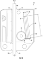
- Figure 3A depicts a schematic plan view of an elevator safety device 20 according to an exemplary embodiment of the invention in a deactivated standby state.
- Figure 3B depicts the elevator safety device depicted in Figure 3A in an activated state.
- the elevator safety device 20 comprises a housing 22.
- the housing 22 is closed, e.g. by a cover plate, which is not shown in the figures.
- the housing 22 is depicted in an open state without the cover plate, in order to allow showing the internal structure of the elevator safety device 20.
- a first opening 24a is formed in a top portion of the housing 22, and a second opening 24b is formed in a bottom portion of the housing 22.
- the two openings 24a, 24b provide a passage 25 extending through the elevator safety device 20, which allows an elevator guide member 14, 15 to pass through the elevator safety device 20.
- the elevator safety device 20 comprises a first engagement member 26, in particular a brake shoe 26, and a second engagement member 28, which is provided as a roller 28.
- the first and second engagement members 26, 28 are arranged opposite to each other with a gap formed in between.
- the gap is part of the passage 25 extending through the elevator safety device 20, and it is configured for accommodating a portion of a guide member 14, 15 of the elevator system 2 extending in a longitudinal direction, in particular in a vertical direction.
- the first engagement member / brake shoe 26 is supported by the housing 22 on a first side of the elevator guide member 14, 15 passing through the elevator safety device 20.
- the second engagement member / roller 28 is arranged on a second of side of the guide member 14, 15 passing through the elevator safety device 20, so that the guide member 14, 15 extends through the elevator safety device 20 between the first and second engagement members 26, 28.
- the roller 28 is capable to roll along the longitudinal extension of the guide member 14, 15.
- the elevator safety device 20 further comprises a spring assembly 30, which is arranged on the second of side of the guide member 14, 15.
- the spring assembly 30 comprises at least one leaf spring 32.
- the spring assembly 30 may comprise a plurality of leaf springs 32.
- the spring assembly 30 may in particular comprise a plurality of leaf springs 32 that are arranged in a sandwich structure on top of each other forming a stack of lead springs 32.
- the spring assembly 30 may have a length L of not more than 60 mm.
- the spring assembly 30 may in particular have a length of 54 mm to 58 mm.
- the thickness of the spring assembly 30 depends on its length and on the load the elevator safety device 2 is designed for.
- the spring assembly 30 may, for example, have a thickness at its thinnest point, which is in the range of between 3 mm and 5 mm.
- a spring assembly 30, which is designed for heavier loads and which is formed as a stack comprising a plurality of leaf springs 32, may, for example, have a total thickness of more than 15 mm.
- the spring assembly 30 has a fixed end 30a, which is fixed to the housing 22, and an opposite free end 30b, which is not fixed to the housing 22, so that it is movable with respect to the housing 22.
- the elevator safety device 20 may include a fixture 34, which is configured for fixing the fixed end 30a of the spring assembly 30 to the housing 22.
- the fixture 34 may be mounted to the housing 22. Alternatively, the fixture 34 may be formed integrally with the housing 22.
- the spring assembly 30 may be fixed within the fixture 34 by fixing elements, which are not shown in Figure 3 .
- Such fixing elements may include screws or bolts, extending trough the spring assembly 30.
- the spring assembly 30 may also be fixed to the fixture 34 by clamping, soldering, welding or adhesive bonding.
- the spring assembly 30 extends at an angle with respect to the guide member 14, 15, defining a tapered region between the guide member 14, 15 and the spring assembly 30.
- the free end 30b of the spring assembly 30 is arranged closer to the guide member 14, 15 than the fixed end 23b of the spring assembly 30.
- the spring assembly 30 may, for example, be arranged at an angle in the range of between 3° and 15° with respect to the guide member 14, 15.
- the roller 28 is movably arranged within the tapered region defined by the guide member 14, 15 and the spring assembly 30.
- the roller 28 When the elevator safety device 20 is in a standby configuration, as it is depicted in Figure 3A , in which the elevator safety device 20 is not activated, the roller 28 is located in a standby position, in which it does not contact the guide member 14, 15. In the standby configuration, the elevator safety device 20 and, in consequence, an elevator car 6 or an elevator counterweight 21, to which the elevator safety device 20 is mounted, are capable to move freely along the guide member 14.
- the standby position of the roller 28 may, in particular, be in the vicinity to the fixed end 23b of the spring assembly 30, as it is illustrated by the roller 28 depicted in Figure 3A .
- the roller 28 is moved towards the guide member 14, 15 by an activation mechanism, which is not depicted in the figures.
- roller 28 contacting the guide member 14, 15 results in a frictional engagement between the roller 28 and the guide member 14, 15.
- a downward movement of the elevator safety device 20 with respect to the guide member 14, 15 causes the roller 28 to roll along the guide member 14, 15 on one side (the left side of the roller in Figures 3A and 3B ) and to roll upwards along the spring assembly 30 on the other side (the right side of the roller 28 in Figures 3A and 3B ).
- the roller 28 presses against the guide member 14, 15, generating a braking force between the guide member 14, 15 and the brake shoe 26 of the elevator safety device 20. Said braking force brakes the movement of the elevator safety device 20 with respect to the guide member 14, 15, until said movement has been stopped.
- a groove 31 may be formed within a surface of the spring assembly 30 facing the guide member 14, 15, and a corresponding collar 29 may be formed on the circumferential surface of the roller 28.
- the collar 29 formed on the roller 28 may be received within the groove 31, which is formed within the surface of the spring assembly 30, for guiding the movement of the roller 28 along the spring assembly 30.
- the elevator safety device 20 may further comprise a stopper 36, which is located in the vicinity of the free end 30b of the spring assembly 30, and which is configured for preventing the roller 28 from moving beyond the free end 30b of the spring assembly 30.
- the stopper 36 may be attached to and supported by the housing 22.
- the stopper 36 may also be formed integrally with the housing 22, i.e. as a portion of the housing 22.
- the elevator safety device 20 depicted in Figures 3A and 3B is configured for braking a downward movement of the elevator safety device 20 with respect to the guide member 14, 15.
- An elevator safety device 20 which is configured for braking an upward movement of the elevator safety device 20 with respect to the guide member 14, 15, would be oriented in an upside down orientation with respect to the orientation depicted in Figures 3A and 3B , i.e. in an orientation, in which the fixed end 30a of the spring assembly 30 is oriented towards the top and the free end 30b of the spring assembly 30, which is closer to the guide member 14, 15 than the fixed end 30a, is oriented towards the bottom.
- the force exerted by the roller 28 onto the spring assembly 30 deforms the spring assembly 30 in a lateral direction, i.e. in a direction which is oriented transversely, in particular perpendicularly, to the longitudinal extension of the spring assembly 30.
- the force, which is exerted by the roller 28 onto the spring assembly 30, may in particular bend the free end 32b of the spring assembly 30 elastically away from the guide member 14, 15, as it is depicted in Figure 3B .
- an elastic reactive force of the spring assembly 30 is generated, which presses the roller 28 elastically against the guide member 14, 15, when the roller 28 moves towards the free end 32b of the spring assembly 30.
- the elevator safety device 20 may comprise a support structure for supporting at least a portion of the spring assembly 30 and/or for limiting the bending of the spring assembly 30 caused by the roller 28.
- Support structures depicted in Figures 4 to 6 are shown only exemplarily. In other words, the support structures, which may be employed in elevator safety devices 20 according to exemplary embodiments of the invention, are not restricted to the support structure shown in Figures 4 to 6 . Elevator safety devices 20 according to exemplary embodiments of the invention may include further support structures, which are not explicitly depicted in the figures.
- Figure 4 depicts a support structure according to an exemplary embodiment of the invention.
- the first support member 40 is arranged in the vicinity of the free end 30b of the spring assembly 30 on the side facing away from the roller 28.
- the first support member 40 does not securely fix the free end 30b of the spring assembly 30 to the housing 22. Instead, the first support member 40 is arranged in some distance from the free end 30b of the spring assembly 30. The distance between the first support member 40 and the free end 30b of the spring assembly 30 allows the free end 30b of the spring assembly 30 to bent away from the guide member 14, 15, when the roller 28 is moved into its wedged position in the vicinity of the free end 30b of the spring assembly 30, as it is illustrated by the dashed lines in Figure 4 .
- a second support member 42 may be provided on the same side of the spring assembly 30 as the first support member 40.
- the second support member 42 may be arranged at a position in between the first support member 40 and the the fixed end 30a of the spring assembly 30, in particular in the vicinity of the fixed end 30a of the spring assembly 30, in order to restrict the bending of the spring assembly 30.
- a third support member 44 may be provided on the same side of the spring assembly 30 as the roller 28, i.e. on the side of the spring assembly 30, which is opposite to side on which the first support member 40 is arranged.
- Providing two or more support members 40, 42, 44 along the longitudinal direction of the spring assembly 30 for restricting the bending of different portions of the spring assembly 30 may allow for defining a bending contour, in particular a curved bending contour, of the spring assembly 30. Defining a bending contour of the spring assembly 30 may allow adjusting the elastic properties of the spring assembly 30. In other words, defining a bending contour of the spring assembly 30 may allow adjusting the forces, which are exerted by the spring assembly 30 onto the roller 28, when the roller 28 moves from its starting position in the vicinity of the fixed end 30a of the spring assembly 30 into its wedged position in the vicinity of the free end 30b of the spring assembly 30.
- FIG. 5 An exemplary embodiment of a support structure comprising a plurality of support members 40, 42, 44 defining a curved bending contour of the spring assembly 30 is schematically depicted in Figure 5 .
- the support structure may also comprise at least one elongated support member 48, which extends along an elongated portion of the spring assembly 30.
- FIG. 6 An exemplary embodiment of a support structure comprising such an elongated support member 48 is depicted in Figure 6 .
- the elongated support member 48 has a curved contour facing the spring assembly 30.
- the roller 28 moves from its starting position in the vicinity of the fixed end 30a of the spring assembly 30 towards the wedged position in the vicinity of the free end 30b of the spring assembly 30, the spring assembly 30 is bent by the roller 28 so that it extends along the curved contour of the the elongated support member 48.
- the elevator safety device 20 may comprise two or more elongated support members 48, which may be arranged next to each other along the longitudinal extension of the spring assembly 30.
- Each elongated support member 48 may have a contour, in particular a curved contour, which extends along a portion of the spring assembly 30, respectively.
- the elongated support member 48 depicted in Figure 6 is depicted as having a continuously curved contour. In alternative embodiments, which are not explicitly depicted in the figures, the elongated support member(s) 48 may have a less smooth contour, for example a contour with one or more kinks.
Landscapes
- Engineering & Computer Science (AREA)
- Mechanical Engineering (AREA)
- Cage And Drive Apparatuses For Elevators (AREA)
Abstract
An elevator safety device (20) comprises a housing (22) configured for being attached to an elevator car (6) or to an elevator counterweight (21) of an elevator system (2), the housing (22) comprising a passage (25) for allowing a guide member (14, 15) to pass through; a brake shoe (26) attached to the housing (22) and located on a first side of the guide member (14, 15) passing through the passage (25); a spring assembly (30) arranged on a second of side of the guide member (14, 15) passing through the passage (25) and comprising at least one leaf spring (32), the spring assembly (30) having a fixed end (30a), which is fixed to the housing (22), and an opposite free end (30b), which is not fixed to the housing (22); and a roller (28). The spring assembly (30) extends at an angle with respect to the guide member (14, 15), defining a tapered region between the guide member (14, 15) and the spring assembly (30), wherein the free end (30b) of the spring assembly (30) is arranged closer to the guide member (14, 15) than the fixed end (30a) of the spring assembly (30). The roller (28) is, at least in an activated condition of the elevator safety device (20), located within said tapered region defined by the spring assembly (30) and the guide member (14, 15). The roller (28) is capable of moving along the spring assembly (30) towards the free end (30b) of the spring assembly (30) into a wedged condition between the spring assembly (30) and the guide member (14, 15).
Description
- The invention relates to an elevator safety device. The invention further relates to an elevator car, to an elevator counterweight and to an elevator system respectively comprising an elevator safety device, and to a method of activating an elevator safety device.
- An elevator system typically comprises at least one elevator car, which is configured for moving along a hoistway extending between a plurality of landings, and a driving member, which is configured for driving the elevator car. The elevator system may further include an elevator counterweight moving concurrently and in opposite direction with respect to the elevator car. In order to ensure a safe operation, an elevator system usually comprises at least one elevator safety device. The at least one elevator safety device is configured for braking the movement of the elevator car and/or the elevator counterweight relative to a guide member, such as a guide rail, in an emergency situation, for example when the movement of the elevator car and/or of the elevator counterweight exceeds a predetermined speed and/or acceleration. An elevator safety device usually includes at least one engagement member that is configured for engaging with the guide member for braking the movement of the elevator safety device along the guide member, when the elevator safety device is activated.
- Currently available elevator safety devices have a relatively large size, in particular a relatively long extension in the moving direction along the guide member.
- It would therefore be beneficial to provide an improved elevator safety device for an elevator system, which may have smaller dimensions, in particular a smaller dimension in the moving direction along the guide member.
- According to an exemplary embodiment of the invention, an elevator safety device comprises a housing, which is configured for being attached to an elevator car or to an elevator counterweight. The housing comprises a passage for allowing an elevator guide rail to pass through. The elevator safety device further comprises a brake shoe attached to the housing and located on a first side of the elevator guide rail passing through the passage; and a spring assembly arranged on a second of side of the guide rail passing through the passage and comprising at least one leaf spring. The spring assembly has a fixed end, which is fixed to the housing, and an opposite free end, which is not fixed to the housing. The spring assembly extends at an angle with respect to the guide rail, defining a tapered region between the guide rail and the spring assembly, wherein the free end of the spring assembly is arranged closer to the guide rail than the fixed end of the spring assembly. The elevator safety device further comprises a roller. At least in an activated condition of the elevator safety device, the roller is located within the tapered region defined by the spring assembly and the guide rail. The roller is further capable of moving along the spring assembly towards the free end of the spring assembly into a wedged condition between the spring assembly and the guide rail.
- Exemplary embodiments of the invention also include a method of activating an elevator safety device according to an exemplary embodiment of the invention, wherein the method includes: moving the roller towards the guide rail so that the roller is sandwiched between the guide rail and the spring assembly; the roller is moved due to frictional engagement with the guide rail towards the free end of the spring assembly, when the elevator safety device moves along the guide rail; and the roller elastically bends the free end of the spring assembly away from the guide rail.
- Providing the spring assembly with a free end, which is not fixed to the housing so that it is movable with respect to the housing, allows for reducing the length of the spring assembly in the longitudinal direction. In consequence, the elevator safety device may have a smaller size, in particular a smaller dimension in the moving direction along the guide member.
- As a result, the weight, the amount of necessary materials and the costs of the elevator safety device may be reduced.
- A number of optional features of an elevator safety device according to exemplary embodiment of the invention are set out in the following. These features may be realized in particular embodiments, alone or in combination with any of the other features, unless explicitly stated otherwise.
- A portion of the spring assembly, which is adjacent to the free end of the spring assembly, may be configured for being elastically bent away from the guide rail by the roller, as the roller moves towards the free end of the spring assembly. In such a configuration, the bent spring assembly assembly exerts an elastic force onto the roller, pressing the roller elastically against the guide rail. This results in generating an elastic braking force for reliably braking the movement of the elevator safety device with respect to the guide rail.
- The elevator safety device may comprise at least one support member, which is configured for supporting a portion of the spring assembly and/or for limiting the bending of the spring assembly caused by the roller. Providing such a support member may prevent the spring assembly from excessively bending. An excessive bending of the spring assembly could result in damaging or even destroying the spring assembly. An excessive bending of the spring assembly could further prevent the spring assembly from providing a sufficiently large braking force, i.e. a braking force that is large enough for ensuring a secure braking of the elevator car or of the elevator counterweight, respectively.
- The elevator safety device may comprise a plurality of supports. The plurality of supports may be arranged along a longitudinal extension of the spring assembly. The plurality of supports may define a bending contour of the spring assembly. This may allow enhancing the braking capabilities of the elevator safety device.
- The elevator safety device may comprise at least one elongated support member, which extends over an elongated portion of the spring assembly and defines a bending contour of the spring assembly. The at least one support member may in particular be an at least partially curved support member, defining a curved bending contour.
- The at least one support member may have a continuous or smooth contour. Alternatively, the at least one support member may have a contour comprising at least one kink.
- The elevator safety device may comprise a fixture, which is configured for fixing the fixed end of the spring assembly to the housing. The fixture may be configured for accommodating the fixed end of the spring assembly. The fixture may be configured for fixing the spring assembly by employing fixing elements, such as screws or bolts, extending through the spring assembly. Alternatively, the fixture may be configured for fixing the spring assembly by clamping, soldering, welding or adhesive bonding.
- The fixture may be attached to the housing. Alternatively, the fixture may be provided by and/or formed integrally with a portion of the housing. Forming the fixture integrally with the housing may facilitate the manufacturing of the elevator safety device, as the manufacturing steps of producing a separate fixture and attaching the separately produced fixture to the housing may be omitted.
- The spring assembly may comprise a plurality of leaf springs. The plurality of leaf springs may, in particular, be arranged in a sandwich-structure on top of each other forming a stack of leaf springs. A plurality of leaf springs, in particular a plurality of leaf springs arranged in a sandwich-structure, provide a strong spring assembly, which is capable of reliably providing sufficiently large braking forces.
- The spring assembly may have a length of not more than 60 mm. The spring assembly may in particular have a length in the range of between 54 mm and 58 mm. Spring assemblies having a length in this range have been found as reliably providing sufficiently large braking force, and, simultaneously allow reducing the dimensions of the elevator safety device.
- The spring assembly of the support member depends on its length and on the load the elevator safety device is designed for.
- If the spring assembly consists of a single leaf spring, it may, for example, have a thickness at its thinnest point, which is in the range of between 3 mm and 5 mm. A spring assembly, which is designed for heavier loads and which is formed as a stack comprising a plurality of leaf springs, may, for example, have a total thickness of more than 15 mm.
- A groove may be formed within a surface of the spring assembly facing the guide rail, and a collar may be formed on a circumferential peripheral surface of the roller. Said collar may be received within the groove formed within a surface of the spring assembly for guiding the movement of the roller along the spring assembly.
- The elevator safety device may further comprise a stopper, which is located in the vicinity of the free end of the spring assembly. The stopper may be configured for preventing the roller from moving beyond the free end of the spring assembly.
- The stopper may be attached to and supported by the housing. Alternatively, the stopper may be formed integrally with the housing, i.e. as a portion of the housing. Forming the stopper integrally with the housing may facilitate the manufacturing of the elevator safety device, as the manufacturing steps of producing a separate stopper and attaching the separately produced stopper to the housing may be omitted.
- Exemplary embodiments of the invention further include an elevator car and an elevator counterweight respectively comprising at least one elevator safety device according to an exemplary embodiment of the invention.
- An elevator car and/or an elevator counterweight according to an exemplary embodiment of the invention may include a first elevator safety device according to an exemplary embodiment of the invention and a second elevator safety device according to an exemplary embodiment of the invention.
- In the first elevator safety device, the fixed end of the spring assembly may be a lower end of the spring assembly facing towards the floor of the hoistway, and the free end of the spring assembly may be an upper end of the spring assembly facing towards an upper end of the hoistway.
- In the second elevator safety device, the free end of the spring assembly may be a lower end of the spring assembly facing towards the floor of the hoistway, and the fixed end of the spring assembly may be an upper end of the spring assembly facing towards an upper end of the hoistway.
- Such a combination of the first and second elevator safety devices allows braking the movement of the elevator car or of the elevator counterweight in both moving directions, i.e. an upward movement and a downward movement, along the guide member.
- Exemplary embodiments of the invention also include an elevator system comprising at least one guide member and at least one elevator car and/or at least one elevator counterweight traveling along said at least one guide member, wherein said at least one elevator car and/or at least one elevator counterweight comprise at least one elevator safety device according to an exemplary embodiment of the invention.
- In the following, exemplary embodiments of the invention are described in more detail with respect to the enclosed figures:
-
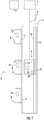
Figure 1 schematically depicts an elevator system according to an exemplary embodiment of the invention. -
Figure 2 shows a perspective view of an elevator car according to an exemplary embodiment of the invention. -
Figure 3A depicts a schematic plan view of an elevator safety device according to an exemplary embodiment of the invention in a deactivated standby state. -
Figure 3B depicts a schematic plan view of the elevator safety device depicted inFigure 3A in an activated state. -
Figure 4 schematically depicts a support structure according to an exemplary embodiment of the invention. -
Figure 5 schematically depicts a support structure according to another exemplary embodiment of the invention. -
Figure 6 schematically depicts a support structure according to yet another exemplary embodiment of the invention. -
Figure 1 schematically depicts anelevator system 2 according to an exemplary embodiment of the invention. - The
elevator system 2 comprises ahoistway 4 extending in a vertical direction between a plurality oflandings 8, which are located on different floors. Theelevator system 2 includes an elevator car 6, which is arranged within thehoistway 4 for being moved between the plurality oflandings 8. The elevator car 6 is movable in particular along a plurality ofcar guide members 14, such as guide rails, extending along the vertical direction of thehoistway 4. Only one of saidcar guide members 14 is visible inFigure 1 . Although only a single elevator car 6 is depicted inFigure 1 , exemplary embodiments of the invention may includeelevator systems 2 comprising a plurality of elevator cars 6 moving in one ormore hoistways 4. - The elevator car 6 is movably suspended by means of a
tension member 3. Thetension member 3 is coupled to anelevator drive 5, which is configured for driving thetension member 3 in order to move the elevator car 6 along the height of thehoistway 4 between the plurality oflandings 8. Theelevator drive 5 is controlled by anelevator system controller 9. - The
tension member 3 may be a rope, e.g. a steel cord, or a belt. Thetension member 3 may be uncoated. Alternatively, thetension member 3 may be coated with a coating, e.g. with a coating having the form of a polymer jacket. In a particular embodiment, thetension member 3 may be a belt comprising a plurality polymer coated steel cords (not shown). Theelevator system 2 may have a traction drive including a traction sheave for driving thetension member 3. - The exemplary embodiment shown in
Figure 1 uses a 1:1 roping for suspending the elevator car 6. The skilled person, however, easily understands that the type of the roping is not essential for the invention and that different kinds of roping, e.g. a 2:1 roping or a 4:1 roping may be used as well. - The
elevator system 2 depicted inFigure 1 also includes anelevator counterweight 21. Theelevator counterweight 21 is attached to thetension member 3 opposite to the elevator car 6 and configured to move along at least onecounterweight guide member 15. The invention may be applied similarly toelevator systems 2 which do not comprise anelevator counterweight 21. - In an alternative configuration, which is not shown in the figures, the
elevator system 2 may be anelevator system 2 without atension member 3. Instead, theelevator system 2 may include, for example, a hydraulic drive or a linear drive. Theelevator system 2 may have a machine room, which is not shown inFigure 1 , or it may be a machine room-less elevator system. - Each
landing 8 is provided with a landingdoor 11, and the elevator car 6 is provided with a correspondingelevator car door 12 for allowing passengers to transfer between alanding 8 and the interior of the elevator car 6, when the elevator car 6 is positioned at therespective landing 8. - Input to the
elevator system controller 9 may be provided vialanding control panels 7a, which are provided on everylanding 8, in particular in the vicinity of thelanding doors 11, and/or via an elevator car control panel 7b, which is provided inside the elevator car 6. - The
landing control panels 7a may comprise elevator hall call buttons and/or destination call buttons. Destination call buttons allow passengers to enter their respective destinations before entering the elevator car 6. In case thelanding control panels 7a are equipped with elevator hall call buttons, no elevator car control panel 7b needs to be provided inside the elevator car 6, since theelevator system 2 is fully controlled by the commands input via thelanding control panels 7a. - The
landing control panels 7a and the elevator car control panel 7b may be connected to theelevator system controller 9 by means of electrical wiring, which are not shown inFigure 1 , in particular by an electric bus, or by means of wireless data connections. - The elevator car 6 is equipped with at least one
elevator safety device 20, which is schematically illustrated at the elevator car 6 inFigure 1 . - The
elevator safety device 20 is operable to brake or at least assist in braking, i.e. slowing or stopping the movement of, the elevator car 6 by engaging with the at least onecar guide member 14. - Alternatively or additionally, the
elevator counterweight 21 may be equipped with at least oneelevator safety device 20, which is configured for engaging with the at least onecounterweight guide member 15. For sake of simplicity of the illustration, theelevator counterweight 21 depicted inFigure 1 is not equipped with anelevator safety device 20. -
Figure 2 is an enlarged view of an elevator car 6 according to an exemplary embodiment of the invention. The elevator car 6 includes acar roof 62, acar floor 64 and a plurality ofcar side walls 66. In combination, thecar roof 62, thecar floor 64 and the plurality ofside walls 66 define aninterior space 68 of the elevator car 6 for accommodating and carryingpassengers 70 and/or cargo. For sake of simplicity of the illustration, cargo is not shown inFigure 2 . - An
elevator safety device 20 according to an exemplary embodiment of the invention is attached to aside wall 66 of the elevator car 6. - Although only a single
elevator safety device 20 is depicted inFigures 1 and2 , respectively, the skilled person will understand that a single elevator car 6 and asingle elevator counterweight 21 may be equipped with a plurality ofsafety devices 20, respectively. - In particular, in a configuration, in which the
elevator system 2 comprises a plurality ofcar guide members 14, each elevator car 6 may be equipped with a plurality ofelevator safety devices 20. Each of the plurality ofelevator safety devices 20 may be associated with one of thecar guide members 14, respectively. - Similarly, in a configuration, in which the
elevator system 2 comprises a plurality ofcounterweight guide members 15, eachelevator counterweight 21 of theelevator system 2 may be equipped with a plurality ofelevator safety devices 20. Eachelevator safety device 20 may be associated with one of thecounterweight guide members 15, respectively. - Alternatively or additionally, two or more
elevator safety devices 20 may be provided on top of each other at thesame sidewall 66 of the elevator car 6 or of theelevator counterweight 21 in order to engage with thesame guide member - A
safety device 20 is usually operable for braking its movement with respect to theguide member elevator counterweight 21 may therefore be equipped with at least twoelevator safety devices 20, which are configured for braking the movement with respect to theguide member - The at least two
elevator safety devices 20 may in particular include a firstelevator safety device 20, which is configured for braking a downward movement of the elevator car 6 /elevator counterweight 21 with respect to theguide member elevator safety device 20, which is configured for braking an upward movement of the elevator car 6 /elevator counterweight 21 with respect to theguide member - In the following, the structure and the operating principles of an
elevator safety device 20 according to an exemplary embodiment of the invention will be described with reference toFigures 3 to 6 . -
Figure 3A depicts a schematic plan view of anelevator safety device 20 according to an exemplary embodiment of the invention in a deactivated standby state.Figure 3B depicts the elevator safety device depicted inFigure 3A in an activated state. - The
elevator safety device 20 comprises ahousing 22. When theelevator safety device 20 is installed within anelevator system 2, thehousing 22 is closed, e.g. by a cover plate, which is not shown in the figures. InFigures 3A and3B , thehousing 22 is depicted in an open state without the cover plate, in order to allow showing the internal structure of theelevator safety device 20. - A
first opening 24a is formed in a top portion of thehousing 22, and asecond opening 24b is formed in a bottom portion of thehousing 22. The twoopenings passage 25 extending through theelevator safety device 20, which allows anelevator guide member elevator safety device 20. - The
elevator safety device 20 comprises afirst engagement member 26, in particular abrake shoe 26, and asecond engagement member 28, which is provided as aroller 28. - The first and
second engagement members passage 25 extending through theelevator safety device 20, and it is configured for accommodating a portion of aguide member elevator system 2 extending in a longitudinal direction, in particular in a vertical direction. - The first engagement member /
brake shoe 26 is supported by thehousing 22 on a first side of theelevator guide member elevator safety device 20. - The second engagement member /
roller 28 is arranged on a second of side of theguide member elevator safety device 20, so that theguide member elevator safety device 20 between the first andsecond engagement members roller 28 is capable to roll along the longitudinal extension of theguide member - The
elevator safety device 20 further comprises aspring assembly 30, which is arranged on the second of side of theguide member - The
spring assembly 30 comprises at least oneleaf spring 32. Optionally, thespring assembly 30 may comprise a plurality of leaf springs 32. Thespring assembly 30 may in particular comprise a plurality ofleaf springs 32 that are arranged in a sandwich structure on top of each other forming a stack of lead springs 32. - The
spring assembly 30 may have a length L of not more than 60 mm. Thespring assembly 30 may in particular have a length of 54 mm to 58 mm. - The thickness of the
spring assembly 30 depends on its length and on the load theelevator safety device 2 is designed for. - If the
spring assembly 30 consists of asingle leaf spring 32, it may, for example, have a thickness at its thinnest point, which is in the range of between 3 mm and 5 mm. - A
spring assembly 30, which is designed for heavier loads and which is formed as a stack comprising a plurality ofleaf springs 32, may, for example, have a total thickness of more than 15 mm. - The
spring assembly 30 has a fixedend 30a, which is fixed to thehousing 22, and an oppositefree end 30b, which is not fixed to thehousing 22, so that it is movable with respect to thehousing 22. - The
elevator safety device 20 may include afixture 34, which is configured for fixing thefixed end 30a of thespring assembly 30 to thehousing 22. Thefixture 34 may be mounted to thehousing 22. Alternatively, thefixture 34 may be formed integrally with thehousing 22. - The
spring assembly 30 may be fixed within thefixture 34 by fixing elements, which are not shown inFigure 3 . Such fixing elements may include screws or bolts, extending trough thespring assembly 30. Thespring assembly 30 may also be fixed to thefixture 34 by clamping, soldering, welding or adhesive bonding. - The
spring assembly 30 extends at an angle with respect to theguide member guide member spring assembly 30. Thefree end 30b of thespring assembly 30 is arranged closer to theguide member spring assembly 30. - The
spring assembly 30 may, for example, be arranged at an angle in the range of between 3° and 15° with respect to theguide member - The
roller 28 is movably arranged within the tapered region defined by theguide member spring assembly 30. - When the
elevator safety device 20 is in a standby configuration, as it is depicted inFigure 3A , in which theelevator safety device 20 is not activated, theroller 28 is located in a standby position, in which it does not contact theguide member elevator safety device 20 and, in consequence, an elevator car 6 or anelevator counterweight 21, to which theelevator safety device 20 is mounted, are capable to move freely along theguide member 14. - The standby position of the
roller 28 may, in particular, be in the vicinity to the fixed end 23b of thespring assembly 30, as it is illustrated by theroller 28 depicted inFigure 3A . - For activating the
elevator safety device 20, theroller 28 is moved towards theguide member - The
roller 28 contacting theguide member roller 28 and theguide member elevator safety device 20 with respect to theguide member roller 28 to roll along theguide member Figures 3A and3B ) and to roll upwards along thespring assembly 30 on the other side (the right side of theroller 28 inFigures 3A and3B ). - Due to the inclined orientation of the
spring assembly 30 with respect to theguide member roller 28 causes theroller 28 to move into a wedged condition, in which theroller 28 is sandwiched between theguide member spring assembly 30, as illustrated inFigure 3B . - In said wedged condition, the
roller 28 presses against theguide member guide member brake shoe 26 of theelevator safety device 20. Said braking force brakes the movement of theelevator safety device 20 with respect to theguide member - Optionally, a
groove 31 may be formed within a surface of thespring assembly 30 facing theguide member corresponding collar 29 may be formed on the circumferential surface of theroller 28. Thecollar 29 formed on theroller 28 may be received within thegroove 31, which is formed within the surface of thespring assembly 30, for guiding the movement of theroller 28 along thespring assembly 30. - The
elevator safety device 20 may further comprise astopper 36, which is located in the vicinity of thefree end 30b of thespring assembly 30, and which is configured for preventing theroller 28 from moving beyond thefree end 30b of thespring assembly 30. - The
stopper 36 may be attached to and supported by thehousing 22. Thestopper 36 may also be formed integrally with thehousing 22, i.e. as a portion of thehousing 22. - The
elevator safety device 20 depicted inFigures 3A and3B is configured for braking a downward movement of theelevator safety device 20 with respect to theguide member - An
elevator safety device 20, which is configured for braking an upward movement of theelevator safety device 20 with respect to theguide member Figures 3A and3B , i.e. in an orientation, in which thefixed end 30a of thespring assembly 30 is oriented towards the top and thefree end 30b of thespring assembly 30, which is closer to theguide member fixed end 30a, is oriented towards the bottom. - When the
roller 28 rolls along thespring assembly 30, as it has been described before, the force exerted by theroller 28 onto thespring assembly 30 deforms thespring assembly 30 in a lateral direction, i.e. in a direction which is oriented transversely, in particular perpendicularly, to the longitudinal extension of thespring assembly 30. - The force, which is exerted by the
roller 28 onto thespring assembly 30, may in particular bend the free end 32b of thespring assembly 30 elastically away from theguide member Figure 3B . In consequence, an elastic reactive force of thespring assembly 30 is generated, which presses theroller 28 elastically against theguide member roller 28 moves towards the free end 32b of thespring assembly 30. - The
elevator safety device 20 may comprise a support structure for supporting at least a portion of thespring assembly 30 and/or for limiting the bending of thespring assembly 30 caused by theroller 28. - Possible configurations of such support structures are schematically illustrated in
Figures 4 to 6 . In order to enhance the clarity of the illustration, only the most essential components of theelevator safety device 20 are schematically depicted inFigures 4 to 6 . The skilled person understands that these components belong to anelevator safety device 20 as it is depicted inFigure 3 . - In
Figures 4 to 6 , the deactivated stationary configuration of theelevator safety device 20 is depicted by solid lines, and the activated configurations of theroller 28 and thespring assembly 30 are depicted by dashed lines. - It its noted that the support structures depicted in
Figures 4 to 6 are shown only exemplarily. In other words, the support structures, which may be employed inelevator safety devices 20 according to exemplary embodiments of the invention, are not restricted to the support structure shown inFigures 4 to 6 .Elevator safety devices 20 according to exemplary embodiments of the invention may include further support structures, which are not explicitly depicted in the figures. -
Figure 4 depicts a support structure according to an exemplary embodiment of the invention. In the embodiment depicted inFigure 4 , thefirst support member 40 is arranged in the vicinity of thefree end 30b of thespring assembly 30 on the side facing away from theroller 28. - The
first support member 40 does not securely fix thefree end 30b of thespring assembly 30 to thehousing 22. Instead, thefirst support member 40 is arranged in some distance from thefree end 30b of thespring assembly 30. The distance between thefirst support member 40 and thefree end 30b of thespring assembly 30 allows thefree end 30b of thespring assembly 30 to bent away from theguide member roller 28 is moved into its wedged position in the vicinity of thefree end 30b of thespring assembly 30, as it is illustrated by the dashed lines inFigure 4 . - Optionally, a
second support member 42 may be provided on the same side of thespring assembly 30 as thefirst support member 40. Thesecond support member 42 may be arranged at a position in between thefirst support member 40 and the thefixed end 30a of thespring assembly 30, in particular in the vicinity of thefixed end 30a of thespring assembly 30, in order to restrict the bending of thespring assembly 30. - Alternatively or additionally to the
second support member 42, athird support member 44 may be provided on the same side of thespring assembly 30 as theroller 28, i.e. on the side of thespring assembly 30, which is opposite to side on which thefirst support member 40 is arranged. - Providing two or
more support members spring assembly 30 for restricting the bending of different portions of thespring assembly 30 may allow for defining a bending contour, in particular a curved bending contour, of thespring assembly 30. Defining a bending contour of thespring assembly 30 may allow adjusting the elastic properties of thespring assembly 30. In other words, defining a bending contour of thespring assembly 30 may allow adjusting the forces, which are exerted by thespring assembly 30 onto theroller 28, when theroller 28 moves from its starting position in the vicinity of thefixed end 30a of thespring assembly 30 into its wedged position in the vicinity of thefree end 30b of thespring assembly 30. - An exemplary embodiment of a support structure comprising a plurality of
support members spring assembly 30 is schematically depicted inFigure 5 . - The support structure may also comprise at least one
elongated support member 48, which extends along an elongated portion of thespring assembly 30. - An exemplary embodiment of a support structure comprising such an
elongated support member 48 is depicted inFigure 6 . In the embodiment depicted inFigure 6 , theelongated support member 48 has a curved contour facing thespring assembly 30. When theroller 28 moves from its starting position in the vicinity of thefixed end 30a of thespring assembly 30 towards the wedged position in the vicinity of thefree end 30b of thespring assembly 30, thespring assembly 30 is bent by theroller 28 so that it extends along the curved contour of the theelongated support member 48. - Only a single
elongated support member 48 extending basically along the full length of thespring assembly 30 is depicted inFigure 6 . In alternative embodiments, which are not explicitly depicted in the figures, theelevator safety device 20 may comprise two or moreelongated support members 48, which may be arranged next to each other along the longitudinal extension of thespring assembly 30. Eachelongated support member 48 may have a contour, in particular a curved contour, which extends along a portion of thespring assembly 30, respectively. - The
elongated support member 48 depicted inFigure 6 is depicted as having a continuously curved contour. In alternative embodiments, which are not explicitly depicted in the figures, the elongated support member(s) 48 may have a less smooth contour, for example a contour with one or more kinks. - While the invention has been described with reference to exemplary embodiments, it will be understood by those skilled in the art that various changes may be made and equivalents may be substituted for elements thereof without departing from the scope of the invention. In addition many modifications may be made to adopt a particular situation or material to the teachings of the invention without departing from the essential scope thereof. Therefore, it is intended that the invention shall not be limited to the particular embodiment disclosed, but that the invention includes all embodiments falling within the scope of the dependent claims.
-
- 2
- elevator system
- 3
- tension member
- 4q
- hoistway
- 5
- elevator drive
- 7a
- landing control panel
- 7b
- elevator car control panel
- 8
- landing
- 11
- landing door
- 12
- elevator car door
- 14
- car guide member
- 15
- counterweight guide member
- 20
- elevator safety device
- 21
- elevator counterweight
- 22
- housing
- 26
- first engagement member / break shoe
- 28
- second engagement member / roller
- 29
- collar
- 30
- spring assembly
- 31
- groove
- 32
- leaf spring
- 34
- fixture
- 36
- stopper
- 40
- first support member
- 42
- second support member
- 44
- third support member
- 48
- elongated support member
- 62
- car roof
- 64
- car floor
- 66
- side wall
- 68
- interior space
- 70
- passenger
Claims (15)
- Elevator safety device (20) comprisinga housing (22) configured for being attached to an elevator car (6) or to an elevator counterweight (21) of an elevator system (2), the housing (22) comprising a passage (25) for allowing a guide member (14, 15) to pass through;a brake shoe (26) attached to the housing (22) and located on a first side of the guide member (14, 15) passing through the passage (25);a spring assembly (30) arranged on a second of side of the guide member (14, 15) passing through the passage (25) and comprising at least one leaf spring (32), the spring assembly (30) having a fixed end (30a), which is fixed to the housing (22), and an opposite free end (30b), which is not fixed to the housing (22); anda roller (28);wherein the spring assembly (30) extends at an angle with respect to the guide member (14, 15), defining a tapered region between the guide member (14, 15) and the spring assembly (30), wherein the free end (30b) of the spring assembly (30) is arranged closer to the guide member (14, 15) than the fixed end (30a) of the spring assembly (30);wherein the roller (28) is, at least in an activated condition of the elevator safety device (20), located within said tapered region defined by the spring assembly (30) and the guide member (14, 15); andwherein the roller (28) is capable of moving along the spring assembly (30) towards the free end (30b) of the spring assembly (30) into a wedged condition between the spring assembly (30) and the guide member (14, 15).
- Elevator safety device (20) according to claim 1, wherein a portion of the spring assembly (30) adjacent to the free end (30b) of the spring assembly (30) is configured for being bent away from the guide member (14, 15) by the roller (28), when/as the roller (28) moves towards the free end (30b) of the spring assembly (30).
- Elevator safety device (20) according to claim 1 or 2, further comprising at least one support member (40, 42, 44, 48) for supporting a portion of the spring assembly (30) and/or for limiting a bending of the spring assembly (30) caused by the roller (28).
- Elevator safety device (20) according to claim 3,comprising a plurality of support members (40, 42, 44, 48) arranged along the spring assembly (30), and/orcomprising at least one support member (40, 42, 44, 48) extending over an elongated portion of the spring assembly (30); wherein the at least one support member (40, 42, 44, 48) is in particular an at least partially curved support member (40, 42, 44, 48).
- Elevator safety device (20) according to any of the preceding claims comprising a fixture (34), which fixes the fixed end (30a) of the spring assembly (30) to the housing (22); wherein the fixture (34) in particular accommodates the fixed end (30a) of the spring assembly (30).
- Elevator safety device (20) according to claim 5, wherein the fixture (34) is provided by and/or formed integrally with a portion of the housing (22).
- Elevator safety device (20) according to any of the preceding claims, wherein the spring assembly (30) comprises a plurality of leaf springs (32), wherein the plurality of leaf springs (32) are in particular arranged in a sandwich-structure on top of each other forming a stack of lead springs (32).
- Elevator safety device (20) according to any of the preceding claims, wherein the spring assembly (30) has a length (L) of not more than 60 mm, wherein the spring assembly (30) has in particular a length of 54 mm to 58 mm.
- Elevator safety device (20) according to any of the preceding claims, wherein a groove (31) is formed within a surface of the spring assembly (30) facing the guide member (14, 15), wherein a collar (29) is formed on a peripheral surface of the roller (28), and wherein said collar (29) is received within said groove (31) for guiding a movement of the roller (28) along the spring assembly (30).
- Elevator safety device (20) according to claim 9, a stopper (36), which is located in the vicinity of the free end (30b) of the spring assembly (30), and which is configured for preventing the roller (28) from moving beyond the free end (30b) of the spring assembly (30), wherein the stopper (36) is in particular formed by a portion of the housing (22).
- Elevator car (6) or elevator counterweight (21) comprising at least one elevator safety device (20) according to any of claims 1 to 10.
- Elevator car (6) or elevator counterweight (21) according to claim 11 comprising:a first elevator safety device (20) according to any of claims 1 to 10, wherein the fixed end (30a) of the spring assembly (30) is a lower end of the spring assembly (30) facing towards the floor of the hoistway, and wherein the free end (30b) of the spring assembly (30) is an upper end of the spring assembly (30) facing towards an upper end of the hoistway; anda second elevator safety device (20) according to any of claims 1 to 10, wherein the free end (30b) of the spring assembly (30) is a lower end of the spring assembly (30) facing towards the floor of the hoistway, and wherein the fixed end (30a) of the spring assembly (30) is an upper end of the spring assembly (30) facing towards an upper end of the hoistway
- Elevator system comprising an elevator car (6), which is movable along a guide member (14, 15) between a plurality of landings (8); wherein the elevator car (6) is an elevator car (6) according to claim 11 or 12.
- Elevator system according to claim 12 further comprising an elevator counterweight (21), which is configured for moving concurrently and in opposite direction with respect to the elevator car (6), wherein the elevator counterweight (21) is an elevator counterweight (21) according to claim 11 or 12.
- Method of activating an elevator safety device (20) according to any of claims 1 to 10, wherein the method includes moving the roller (28) towards the guide member (14, 15) so thatthe roller (28) is sandwiched between the guide member (14, 15) and the spring assembly (30);the roller (28) is moved due to frictional engagement with the guide member (14, 15) towards the free end (30b) of the at least one leaf spring (32), when the elevator safety device (20) moves along the guide member (14, 15); andthe roller (28) elastically bends the free end (30b) of the at least one leaf spring (32) away from the guide member (14, 15).
Priority Applications (3)
| Application Number | Priority Date | Filing Date | Title |
|---|---|---|---|
| EP23383349.0A EP4574731A1 (en) | 2023-12-21 | 2023-12-21 | Elevator safety device |
| US18/959,857 US20250206571A1 (en) | 2023-12-21 | 2024-11-26 | Elevator safety device |
| CN202411887879.6A CN120191812A (en) | 2023-12-21 | 2024-12-20 | Elevator safety devices |
Applications Claiming Priority (1)
| Application Number | Priority Date | Filing Date | Title |
|---|---|---|---|
| EP23383349.0A EP4574731A1 (en) | 2023-12-21 | 2023-12-21 | Elevator safety device |
Publications (1)
| Publication Number | Publication Date |
|---|---|
| EP4574731A1 true EP4574731A1 (en) | 2025-06-25 |
Family
ID=89542068
Family Applications (1)
| Application Number | Title | Priority Date | Filing Date |
|---|---|---|---|
| EP23383349.0A Pending EP4574731A1 (en) | 2023-12-21 | 2023-12-21 | Elevator safety device |
Country Status (3)
| Country | Link |
|---|---|
| US (1) | US20250206571A1 (en) |
| EP (1) | EP4574731A1 (en) |
| CN (1) | CN120191812A (en) |
Citations (3)
| Publication number | Priority date | Publication date | Assignee | Title |
|---|---|---|---|---|
| US4538706A (en) * | 1983-03-21 | 1985-09-03 | Otis Elevator Company | Progressive safety |
| US9821983B2 (en) * | 2009-12-23 | 2017-11-21 | Otis Elevator Company | Elevator braking device |
| US20220177272A1 (en) * | 2019-03-15 | 2022-06-09 | Inventio Ag | Safety brake device and safety brake method |
Family Cites Families (10)
| Publication number | Priority date | Publication date | Assignee | Title |
|---|---|---|---|---|
| GB1148742A (en) * | 1965-06-01 | 1969-04-16 | Ceccato & Co | A device for locking platform hoists for motor vehicles |
| AT374767B (en) * | 1982-07-06 | 1984-05-25 | Otis Elevator Co | BRAKE DEVICE FOR ELEVATORS |
| US5002158A (en) * | 1990-08-03 | 1991-03-26 | Otis Elevator Company | Elevator safety |
| ES2156730B1 (en) * | 1999-05-28 | 2002-04-01 | Lopla S L | PARACHUTE SYSTEM IN ELEVATOR CABIN, UP AND DOWN ACTION. |
| JP2004262652A (en) * | 2002-09-23 | 2004-09-24 | Inventio Ag | Safety device for elevator |
| KR100520908B1 (en) * | 2003-04-29 | 2005-10-13 | 최용대 | A safety device for an elevator |
| US10421640B2 (en) * | 2017-02-17 | 2019-09-24 | Otis Elevator Company | Elevator braking device including buckling beams |
| EP3677534B1 (en) * | 2019-01-02 | 2021-07-21 | Otis Elevator Company | Elevator safety device actuator |
| EP3736238B1 (en) * | 2019-05-08 | 2023-01-11 | Otis Elevator Company | Mounting apparatus for safety brake |
| CN116281489B (en) * | 2023-03-09 | 2025-07-22 | 杭州沪宁电梯部件股份有限公司 | Bidirectional safety tongs |
-
2023
- 2023-12-21 EP EP23383349.0A patent/EP4574731A1/en active Pending
-
2024
- 2024-11-26 US US18/959,857 patent/US20250206571A1/en active Pending
- 2024-12-20 CN CN202411887879.6A patent/CN120191812A/en active Pending
Patent Citations (3)
| Publication number | Priority date | Publication date | Assignee | Title |
|---|---|---|---|---|
| US4538706A (en) * | 1983-03-21 | 1985-09-03 | Otis Elevator Company | Progressive safety |
| US9821983B2 (en) * | 2009-12-23 | 2017-11-21 | Otis Elevator Company | Elevator braking device |
| US20220177272A1 (en) * | 2019-03-15 | 2022-06-09 | Inventio Ag | Safety brake device and safety brake method |
Also Published As
| Publication number | Publication date |
|---|---|
| CN120191812A (en) | 2025-06-24 |
| US20250206571A1 (en) | 2025-06-26 |
Similar Documents
| Publication | Publication Date | Title |
|---|---|---|
| EP3677534B1 (en) | Elevator safety device actuator | |
| US20120006626A1 (en) | Elevator system including multiple cars within a single hoistway | |
| EP3283425B1 (en) | Elevator system | |
| EP4077191B1 (en) | Guide device for an elevator car and elevator system | |
| KR102211112B1 (en) | Elevator safety gear actuation device | |
| CN110407057B (en) | Elevator safety mechanism actuating device | |
| JP5161563B2 (en) | elevator | |
| US11059698B2 (en) | Elevator safety gear assembly | |
| US20250206571A1 (en) | Elevator safety device | |
| EP4678579A1 (en) | Elevator safety brake arrangement | |
| EP3154893B1 (en) | Elevator system | |
| EP1741660A1 (en) | Elevator apparatus | |
| EP1512652A1 (en) | Elevator | |
| US12577083B2 (en) | Elevator safety device and method of activating an elevator safety device | |
| WO2005121006A1 (en) | Emergency brake device for elevator | |
| EP4717655A1 (en) | Elevator system with a guiding structure comprising at least one guide rail bracket | |
| JP5733892B2 (en) | Elevator safety device | |
| JP7792853B2 (en) | elevator equipment | |
| US11884515B2 (en) | Clamping device and elevator system | |
| CN113581976A (en) | Guide device for an elevator car and elevator system | |
| EP3569546A1 (en) | Elevator safety gear | |
| WO2026009302A1 (en) | Elevator |
Legal Events
| Date | Code | Title | Description |
|---|---|---|---|
| PUAI | Public reference made under article 153(3) epc to a published international application that has entered the european phase |
Free format text: ORIGINAL CODE: 0009012 |
|
| STAA | Information on the status of an ep patent application or granted ep patent |
Free format text: STATUS: THE APPLICATION HAS BEEN PUBLISHED |
|
| AK | Designated contracting states |
Kind code of ref document: A1 Designated state(s): AL AT BE BG CH CY CZ DE DK EE ES FI FR GB GR HR HU IE IS IT LI LT LU LV MC ME MK MT NL NO PL PT RO RS SE SI SK SM TR |
|
| STAA | Information on the status of an ep patent application or granted ep patent |
Free format text: STATUS: REQUEST FOR EXAMINATION WAS MADE |
|
| 17P | Request for examination filed |
Effective date: 20251201 |