EP4574727A1 - Landing device for an elevator system, and elevator system comprising such a landing device - Google Patents
Landing device for an elevator system, and elevator system comprising such a landing device Download PDFInfo
- Publication number
- EP4574727A1 EP4574727A1 EP23218880.5A EP23218880A EP4574727A1 EP 4574727 A1 EP4574727 A1 EP 4574727A1 EP 23218880 A EP23218880 A EP 23218880A EP 4574727 A1 EP4574727 A1 EP 4574727A1
- Authority
- EP
- European Patent Office
- Prior art keywords
- air pressure
- landing
- elevator system
- devices
- landing device
- Prior art date
- Legal status (The legal status is an assumption and is not a legal conclusion. Google has not performed a legal analysis and makes no representation as to the accuracy of the status listed.)
- Pending
Links
Images

Classifications
-
- B—PERFORMING OPERATIONS; TRANSPORTING
- B66—HOISTING; LIFTING; HAULING
- B66B—ELEVATORS; ESCALATORS OR MOVING WALKWAYS
- B66B1/00—Control systems of elevators in general
- B66B1/34—Details, e.g. call counting devices, data transmission from car to control system, devices giving information to the control system
-
- B—PERFORMING OPERATIONS; TRANSPORTING
- B66—HOISTING; LIFTING; HAULING
- B66B—ELEVATORS; ESCALATORS OR MOVING WALKWAYS
- B66B1/00—Control systems of elevators in general
- B66B1/34—Details, e.g. call counting devices, data transmission from car to control system, devices giving information to the control system
- B66B1/46—Adaptations of switches or switchgear
- B66B1/468—Call registering systems
Definitions
- the invention relates to a landing device for elevator systems.
- the invention further relates to an elevator system comprising a plurality of landing devices and to a method of assigning a plurality of landing devices to the plurality of landings of an elevator system.
- An elevator system comprises at least one elevator car configured for traveling along a hoistway between a plurality of landings located at different floors.
- Landing devices are installed at the landings.
- the landing devices allow passengers to input control commands for controlling the operation of the elevator system.
- each landing device needs to be unambiguously assigned to one of the plurality of landings of the elevator system.
- a manual assignment of a plurality of landing devices to the plurality of landings of an elevator system is laborious and prone to errors.
- landing devices for an elevator system which may be assigned to the plurality of landings of an elevator system more reliably and more easily than conventional landing devices. It is further desirable to provide an improved method of assigning a plurality of landing devices to the plurality landings of the elevator system, wherein the method allows for assigning the landing devices more reliably and more easily than conventional methods.
- a landing device which is configured for being installed at a landing of an elevator system, comprises: a landing device air pressure sensor, which is configured for detecting a local air pressure in the environment of the landing device and for providing a corresponding air pressure value; and a communication device, which is configured for communicating the air pressure value provided by the landing device air pressure sensor to a controller of the elevator system.
- the controller may in particular be configured for issuing an initialization request for triggering each of the landing devices to detect the local air pressure in the environment of the respective landing device, and to communicate an air pressure value corresponding to the detected pressure to the controller of the elevator system.
- Exemplary embodiments of the invention also include a method of assigning a plurality of landing devices of an elevator system to different landings of the elevator system, wherein each of the landing devices comprises a landing device air pressure sensor; and wherein the method includes: arranging the landing devices at different landings of the elevator system; measuring, with the landing device air pressure sensor, the local air pressure in the environment of the respective landing device and providing an air pressure value corresponding to the measured local air pressure; communicating the air pressure values provided by the landing device air pressure sensors of the plurality of landing devices to a controller of the elevator system; sorting the received air pressure values in ascending or descending order; and assigning each of the plurality the landing devices to one of the plurality of landings of the elevator system based on the sorted air pressure values.
- Landing devices and a method of assigning a plurality of landing devices to the different landings of the elevator system allows for an automatic assignment of a plurality of landing devices to the different landings of an elevator system without providing any additional input, in particular without providing manual inputs.
- the plurality of landing devices may be assigned to the different landings faster and more reliably than with conventional methods.
- the communication device may be configured for communicating with the controller via wired data connections.
- wired data connections may include an RS485-interface, an RSL-Bus, or a CAN-bus.
- RS485-interfaces, RSL-Buses, and CAN-buses are frequently used for allowing communication in elevator systems.
- wired data connections may also be used for communicating the air pressure values from the landing devices to the controller.
- Landing devices according to exemplary embodiments of the invention, which are configured for using such data connections may be added to existing elevator systems without redesigning the elevator system, in particular without adding additional communication paths to the elevator system.
- the communication device of a landing device may also be configured for communicating with the controller via a wireless data connection.
- a wireless data connection may, for example, be implemented using WLAN or Bluetooth ® technology.
- Using a wireless data connection for communicating the air pressure values from the landing device air pressure sensors to the controller avoids the need of providing electric wiring between the landing devices and the controller. This may be beneficial in particular in large elevator systems with a large number of landings, in which the distances between the landing devices and the controller may be long.
- a landing device may comprise at least one input device.
- the at least one input device may in particular include a button or knob, which allows for entering an input into the landing device.
- the communication device may be configured for forwarding the input, which has been entered using the at least one input device, to the controller of the elevator system.
- an additional communication device which is provided separately from the communication device configured for communicating the air pressure values to the controller of the elevator system, may be employed for forwarding the input, which has been entered via the at least one input device, to the controller.
- the input devices may comprise elevator hall call buttons and/or destination call buttons. Destination call buttons allow passengers to enter their respective destinations at the landing device before entering the elevator car.
- the landing devices may comprise other types of input devices, such as touchscreens, electronic card readers, electronic key readers, and similar devices, which allow inputting control commands for the controller.
- the landing device may include at least one signaling device, for example a visual signaling or an acoustic signaling device, which allows for outputting a signal from the landing device.
- the signals output by the signaling device may, for example, include visual signals, such as lights, and/or acoustic signals, such as indicator tones, which may indicate the arrival of the elevator car at the respective landing, visual signals and/or acoustic signals indicating the current direction of movement of the elevator car, and/or visual signals and/or acoustic signals indicating the landing at which the elevator car is currently positioned.
- Landing devices according to exemplary embodiments of the invention may include landing devices comprising at least one input device and at least one signaling device. Landing devices according to exemplary embodiments of the invention may further include landing devices comprising at least one input device, but no signaling device. Landing devices according to exemplary embodiments of the invention may also include landing devices comprising at least one signaling device but no input device.
- a landing device comprising at least one signaling device may further comprise a communication device, which is configured for receiving a control signal, comprising instructions for operating the signal device, from the controller of the elevator system.
- the communication device which is configured for receiving a control signal from the controller, may be identical to the communication device that is configured for forwarding an input, which has been entered via the at least one input device, to the controller of the elevator system.
- the communication device which is configured for receiving a control signal from the controller, may be a separate communication device.
- the landing device air pressure sensor may be a surface mounted device (SMD).
- SMD surface mounted device
- the controller may be configured for repeatedly receiving air pressure values from the at least two landing devices for evaluating the received air pressure values, and for issuing an alarm, in particular a fire alarm, in case an abnormality is detected in the received air pressure values.
- the abnormality in the received air pressure values may, in particular, include an unusual rapid change of the received air pressure data.
- an unusual rapid change of the local air pressure include changes of the local air pressure that are faster than the air pressure changes caused by natural meteorological effects. Such rapid changes of the local air pressure may in particular result from fire within the hoistway or at one of the landings.
- the elevator system may further comprise an elevator car air pressure sensor, which is installed within the elevator car, and which is configured for providing an air pressure value that corresponds to the local air pressure at the elevator car.
- the controller may be configured for successively moving the elevator car to at least one landing, at which a landing device is installed, preferably to all landings at which a landing device is installed, and for comparing an air pressure value that is provided by the elevator car air pressure sensor with an air pressure value that is provided by the landing device air pressure sensor located at the respective landing.
- the elevator system comprises two or more landing devices, which are assigned to the same landing, and/or two different landings, which are arranged at the same height, so that the local are pressure at the two landings is basically the same, additional information may be used for assigning the landing devices to specific positions at the possible landings.
- Such additional information may, for example, be provided by a position detection system.
- a position detection system may be configured for determining the current position of a landing device at a landing.
- the position detection system may, for example, be configured for determining the distance of the landing device from at least one transmitter, which may be employed for wireless data communication, and which is provided at or in the vicinity of the respective landing.
- the controller may also be configured for requesting a manual input of additional information, which allows assigning the landing devices to specific positions at the same landing, or to specific positions at different landings, which are arranged at the same height.
- Fig. 1 schematically depicts an elevator system 2 comprising a hoistway 4 extending in a vertical direction between a plurality of landings 8a-8c, which are located on different floors, i.e. at different heights above a bottom of the hoistway 4.
- the elevator system 2 comprises only three landings 8a-8c.
- an elevator system 2 according to an exemplary embodiment of the invention may also comprise only two landings 8a-8c or more than three landings 8a-8c, respectively.
- the elevator system 2 further comprises an elevator car 6, which is movably suspended within the hoistway 4 by means of a tension member 3.
- the tension member 3 for example a rope or belt, is coupled to an elevator drive 5, which is configured for driving the tension member 3 in order to move the elevator car 6 along the longitudinal direction / height of the hoistway 4 between the plurality of landings 8a-8c.
- the exemplary embodiment of the elevator system 2 shown in Fig. 1 employs a 1:1 roping for suspending the elevator car 6.
- the skilled person easily understands that the type of the roping is not essential for the invention and that different kinds of roping, e.g. a 2:1 roping, may be used as well.
- the elevator system 2 may further include a counterweight, which is not shown in Fig. 1 , moving concurrently and in opposite direction with respect to the elevator car 6.
- the elevator system 2 may be an elevator system 2 without a counterweight, as it is shown in Fig. 1 .
- the elevator system 2 may use a tension member 3, as it is shown in Fig. 1 .
- the elevator system 2 may be an elevator system 2 without a tension member 3, comprising e.g. a hydraulic drive, or a linear drive (not shown).
- the elevator system 2 may have a machine room or may be a machine room-less elevator system 2.
- Each landing 8a-8c is provided with at least one landing door 10, which also may be denoted as elevator hoistway door.
- the elevator car 6 is provided with at least one corresponding elevator car door 11 allowing passengers to transfer between a landing 8a-8c and the interior space of the elevator car 6, when the elevator car 6 is positioned at the respective landing 8a-8c.
- the elevator drive 5 is controlled by a controller 15 of the elevator system 2.
- Input to the controller 15 may be provided via landing devices 7, which are located in the vicinity of the elevator landing doors 10, and/or via an elevator car control device 9, which is located inside the elevator car 6.
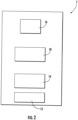
- FIG. 2 An enlarged detailed view of a landing device 7 in accordance with an exemplary embodiment of the invention is depicted in Fig. 2 .
- the landing devices 7 and the elevator car control device 9 comprise an input device 12, which is configured for receiving control commands, such as transportation requests and/or passenger destinations into the controller 15.
- the input devices 12 of the landing devices 7 may comprise elevator hall call buttons and/or destination call buttons. Destination call buttons allow passengers to enter their respective destinations before entering the elevator car 6. In case the landing devices 7 are equipped with elevator hall call buttons, no elevator car control device 9 needs to be provided inside the elevator car 6, since the elevator system 2 is fully controlled by the commands input via the landing devices 7.
- the landing devices 7 and the elevator car control device 9 may comprise other types of input devices 12, such as touchscreens, electronic card readers, electronic key readers, and similar devices, which allow inputting control commands for the controller 15.
- At least one of the landing devices 7 may further comprise a signaling device 19, which allows for outputting signals including information for the passengers.
- the at least one signaling device 19 may be controlled by output commands, which may be transmitted from the controller 15 to the landing device 7 at the respective landing 8a-8c.
- the communication device 18 of each landing device 7 is configured for transmitting an air pressure value, which corresponds to the local air pressure p detected by the landing device air pressure sensor 16 of the respective landing device 7 to the controller 15 of the elevator system 2.
- each landing device 7 may comprise a dedicated air pressure communication device, which is provided separately from the previously described communication device 18, and which is configured for communicating the air pressure value, which corresponds to the local air pressure p, to the controller 15 of the elevator system 2.
- a dedicated air pressure communication device which is provided separately from the previously described communication device 18, and which is configured for communicating the air pressure value, which corresponds to the local air pressure p, to the controller 15 of the elevator system 2.
- two different communication devices 18 are employed for transmitting control commands from the input device 12 and air pressure values provided by the landing device air pressure sensor 16 from the landing device 7 to the controller 15.
- This may include WLAN data communication and/or Bluetooth ® data communication.
- the controller 15 may send an initialization request to landing devices 7.
- the landing device air pressure sensor 16 of each of the landing devices 7 measures the local air pressure p in the environment of the respective landing device 7 and provides a corresponding air pressure value.
- the air pressure communication devices 18 communicate the air pressure value provided by the landing device air pressure sensor 16 together with an unambiguous identifier, which allows the controller 15 to unambiguously identify the respective landing devices 7, to the controller 15.
- the controller 15 has information about all landing devices 7 of the elevator system 2. Said information includes in particular the unambiguous identifiers of all landing devices 7, and the local air pressure values, which have been provided by the landing device air pressure sensors 16 of the landing devices 7.
- the landing devices 7 may repeatedly send this information to the controller 15 in predefined time intervals.
- the controller 15 is configured for sorting the information provided by the landing devices 7 based on the received air pressures values, generating a sorted list of all landing devices 7 of the elevator system 2.
- the received air pressures values may in particular be sorted in an ascending order, or in a descending order.
- the local air pressure p at each of the landings 8a-8c is a function of the height of the respective landing 8a-8c, the local air pressure p at each of the landings 8a-8 decreases in particular with increasing height.
- the order of landing devices 7 in the sorted list corresponds to the positions of the landing devices 7 along the hoistway 4.
- the controller 15 may assign the plurality landing devices 7 successively to the plurality of landings 8a-8c of the elevator system 2.
- the landing device 7 reporting the highest air pressure value p high indicating that the respective landing device 7 is located at the lowest landing 8a, is assigned to the lowest landing 8a of the elevator system 2.
- the landing device 7b reporting the second highest local air pressure value is assigned to the second lowest landing 8b of the elevator system 2.
- the method of assigning the landing devices 7 to the different landings 8a-8c of the elevator system 2 may alternatively start at the top of the hoistway 4 by assigning the landing device 7 reporting the lowest air pressure value p low to the highest landing 8c of the elevator system 2; and then assigning the landing devices 7b, 7c reporting higher local air pressures p successively to the next lower landings 8b, 8c, until the lowest landing 8c has been reached.
- the plurality of landing devices 7 may be automatically assigned to the plurality of landings 8a-8c of the elevator system 2, in particular without the need for human intervention.
- a method of automatically assigning the plurality of landing devices 7 to the plurality of landings 8a-8c according to exemplary embodiments of the present invention may be executed more easily and more conveniently than conventional methods, in which the plurality of landing devices 7 are assigned manually to the different landings 8a-8c, for example by setting addressing switches, which are provided at the landing devices 7.
- a method according to an exemplary embodiment of the invention may considerably reduce the risk of erroneous assignments, in particular the risk of erroneous assignments caused by human errors. In consequence, the method may enhance the operational safety of the elevator system 2.
- the controller 15 may prompt for a manual input in order to allow assigning each landing device 7, which as been assigned to the respective landings 8a-8c, to a specific position at one of these landing 8a-8c.
- each landing device 7, which has been assigned to the same landing 8a-8c, or to two landings 8a-8c on the same floor may be determined by an automatic position detection system.
- an automatic position detection system may, for example, be configured for determining the position, in particular the distance, of the respective landing devices 7 with respect to a transmitter, which may be located at the respective landing 8a-8c in order to allow for wireless data communication.
- the elevator car 6 may be equipped with an elevator car air pressure sensor 20 as well.
- An elevator car 6 that is equipped with an elevator car air pressure sensor 20 may be used for checking the assignments of the landing devices 7 to the different landings 8a-8c.
- the controller 15 may instruct the elevator drive 5 to successively move the elevator car 6 to each of the landings 8a-8c.
- the local air pressure p at the respective landing 8 may be measured with the elevator car air pressure sensor 20 provided at the elevator car 6, and an air pressure value provided by the elevator car air pressure sensor 20 may be transmitted to the controller 15.
- the controller 15 may then compare the air pressure value provided by the elevator car air pressure sensor 20 with an air pressure value provided by the landing device air pressure sensor 16 of the at least one landing device 7, which has been assigned to the respective landing 8a-8c.
- the controller 15 may issue an error signal indicating that the assignment of the respective landing device 7 to the respective landing 8 appears to be erroneous, if the air pressure value provided by the elevator car air pressure sensor 20 differs by more than a predefined tolerance value from the air pressure value provided by the landing device air pressure sensor 16 of the at least one landing device 7.
- the previously described method of assigning the plurality of landing devices 7 to plurality of landings 8a-8c of the elevator system 2 may be repeated.
- the method of checking the assignments of the landing devices 7 to the landings 8a-8c may be repeated as well. This process may be repeated until no error signal is issued, or until a maximum number or repetitions has been reached.
- the landing device air pressure sensors 16 of the landing devices 7, which are located at the plurality of landings 8a-8c, and/or the air pressure sensor 20 provided at the elevator car 6 may be configured to repeatedly measure the local air pressure p at their respective landings 8a-8c.
- the landing device air pressure sensors 16 and the controller 15 may in particular configured for repeatedly checking for rapid changes of the local air pressure, in particular for changes of the local air pressure that are faster than the air pressure changes caused by natural meteorological effects. Such rapid changes of the local air pressure p may result from fire within the hoistway 4 or at one of the landings 8a-8c.
- the controller 15 may therefore be configured for triggering a fire alarm, in case such an unusual rapid change the local air pressure p is detected.
- the elevator system 2 provides the additional functionality of a fire detection system, thereby improving the safety of the building, in which the elevator system 2 is installed.
Landscapes
- Engineering & Computer Science (AREA)
- Automation & Control Theory (AREA)
- Computer Networks & Wireless Communication (AREA)
- Elevator Control (AREA)
Abstract
Landing device (7) for being installed at a landing (8a-8c) of an elevator system (2), the landing device (7) comprising a landing device air pressure sensor (16), which is configured for detecting a local air pressure in the environment of the landing device (7) and for providing a corresponding air pressure value; and a communication device (18), which is configured for communicating the air pressure value provided by the landing device air pressure sensor (16) to a controller (15) of the elevator system (2).
Description
- The invention relates to a landing device for elevator systems. The invention further relates to an elevator system comprising a plurality of landing devices and to a method of assigning a plurality of landing devices to the plurality of landings of an elevator system.
- An elevator system comprises at least one elevator car configured for traveling along a hoistway between a plurality of landings located at different floors.
- Landing devices are installed at the landings. The landing devices allow passengers to input control commands for controlling the operation of the elevator system. In order to allow for a proper operation of the elevator system, each landing device needs to be unambiguously assigned to one of the plurality of landings of the elevator system.
- A manual assignment of a plurality of landing devices to the plurality of landings of an elevator system is laborious and prone to errors.
- It therefore would be desirable to provide landing devices for an elevator system, which may be assigned to the plurality of landings of an elevator system more reliably and more easily than conventional landing devices. It is further desirable to provide an improved method of assigning a plurality of landing devices to the plurality landings of the elevator system, wherein the method allows for assigning the landing devices more reliably and more easily than conventional methods.
- According to an exemplary embodiment of the invention, a landing device, which is configured for being installed at a landing of an elevator system, comprises: a landing device air pressure sensor, which is configured for detecting a local air pressure in the environment of the landing device and for providing a corresponding air pressure value; and a communication device, which is configured for communicating the air pressure value provided by the landing device air pressure sensor to a controller of the elevator system.
- Exemplary embodiments of the invention further include an elevator system comprising an elevator car, which is movable along a hoistway between a plurality of landings; a controller for controlling the operation of the elevator system; and at least two landing devices according to exemplary embodiments of the invention, with the at least two landing devices being located at different landings of the elevator system. The controller is configured for receiving, from the at least two landing devices, air pressure values indicating the air pressure at the respective landing device; and sorting the received air pressure values in ascending or descending order, and assigning the landing devices to different landings of the elevator system according to the sorted air pressure values.
- The controller may in particular be configured for issuing an initialization request for triggering each of the landing devices to detect the local air pressure in the environment of the respective landing device, and to communicate an air pressure value corresponding to the detected pressure to the controller of the elevator system.
- Exemplary embodiments of the invention also include a method of assigning a plurality of landing devices of an elevator system to different landings of the elevator system, wherein each of the landing devices comprises a landing device air pressure sensor; and wherein the method includes: arranging the landing devices at different landings of the elevator system; measuring, with the landing device air pressure sensor, the local air pressure in the environment of the respective landing device and providing an air pressure value corresponding to the measured local air pressure; communicating the air pressure values provided by the landing device air pressure sensors of the plurality of landing devices to a controller of the elevator system; sorting the received air pressure values in ascending or descending order; and assigning each of the plurality the landing devices to one of the plurality of landings of the elevator system based on the sorted air pressure values.
- Landing devices and a method of assigning a plurality of landing devices to the different landings of the elevator system allows for an automatic assignment of a plurality of landing devices to the different landings of an elevator system without providing any additional input, in particular without providing manual inputs. As a result, the plurality of landing devices may be assigned to the different landings faster and more reliably than with conventional methods.
- Air pressure sensors may be added to the landing devices at low costs. In consequence, the invention may be implemented at low costs. It considerably reduces the efforts and costs for assigning the plurality of landing devices to the plurality of landings of the elevator system.
- A number of optional features are set out in the following. These features may be realized in particular embodiments, alone or in combination with any of the other features.
- The communication device may be configured for communicating with the controller via wired data connections. Such a wired data connections may include an RS485-interface, an RSL-Bus, or a CAN-bus. RS485-interfaces, RSL-Buses, and CAN-buses are frequently used for allowing communication in elevator systems. Such wired data connections may also be used for communicating the air pressure values from the landing devices to the controller. Landing devices according to exemplary embodiments of the invention, which are configured for using such data connections, may be added to existing elevator systems without redesigning the elevator system, in particular without adding additional communication paths to the elevator system.
- The communication device of a landing device according to an exemplary embodiment of the invention may also be configured for communicating with the controller via a wireless data connection. Such a wireless data connection may, for example, be implemented using WLAN or Bluetooth® technology. Using a wireless data connection for communicating the air pressure values from the landing device air pressure sensors to the controller avoids the need of providing electric wiring between the landing devices and the controller. This may be beneficial in particular in large elevator systems with a large number of landings, in which the distances between the landing devices and the controller may be long.
- A landing device according to an exemplary embodiment of the invention may comprise at least one input device. The at least one input device may in particular include a button or knob, which allows for entering an input into the landing device. In such a configuration, the communication device may be configured for forwarding the input, which has been entered using the at least one input device, to the controller of the elevator system.
- in an alternative embodiment, an additional communication device, which is provided separately from the communication device configured for communicating the air pressure values to the controller of the elevator system, may be employed for forwarding the input, which has been entered via the at least one input device, to the controller.
- The input devices may comprise elevator hall call buttons and/or destination call buttons. Destination call buttons allow passengers to enter their respective destinations at the landing device before entering the elevator car.
- Additionally or alternatively to elevator hall call buttons and/or destination call buttons, the landing devices may comprise other types of input devices, such as touchscreens, electronic card readers, electronic key readers, and similar devices, which allow inputting control commands for the controller.
- The landing device may include at least one signaling device, for example a visual signaling or an acoustic signaling device, which allows for outputting a signal from the landing device. The signals output by the signaling device may, for example, include visual signals, such as lights, and/or acoustic signals, such as indicator tones, which may indicate the arrival of the elevator car at the respective landing, visual signals and/or acoustic signals indicating the current direction of movement of the elevator car, and/or visual signals and/or acoustic signals indicating the landing at which the elevator car is currently positioned.
- Landing devices according to exemplary embodiments of the invention may include landing devices comprising at least one input device and at least one signaling device. Landing devices according to exemplary embodiments of the invention may further include landing devices comprising at least one input device, but no signaling device. Landing devices according to exemplary embodiments of the invention may also include landing devices comprising at least one signaling device but no input device.
- A landing device comprising at least one signaling device may further comprise a communication device, which is configured for receiving a control signal, comprising instructions for operating the signal device, from the controller of the elevator system.
- The communication device, which is configured for receiving a control signal from the controller, may be identical to the communication device that is configured for forwarding an input, which has been entered via the at least one input device, to the controller of the elevator system. In an alternative embodiment, the communication device, which is configured for receiving a control signal from the controller, may be a separate communication device.
- The landing device air pressure sensor may be a surface mounted device (SMD). Landing device air pressure sensors, which are provided as surface mounted devices (SMDs) need only a small space within the landing device. Further, surface mounted devices are easy to install and they are available at low costs.
- In an elevator system according to an exemplary embodiment of the invention, the controller may be configured for repeatedly receiving air pressure values from the at least two landing devices for evaluating the received air pressure values, and for issuing an alarm, in particular a fire alarm, in case an abnormality is detected in the received air pressure values. The abnormality in the received air pressure values may, in particular, include an unusual rapid change of the received air pressure data.
- In the context of the present invention, an unusual rapid change of the local air pressure include changes of the local air pressure that are faster than the air pressure changes caused by natural meteorological effects. Such rapid changes of the local air pressure may in particular result from fire within the hoistway or at one of the landings.
- The elevator system may further comprise an elevator car air pressure sensor, which is installed within the elevator car, and which is configured for providing an air pressure value that corresponds to the local air pressure at the elevator car.
- In such an elevator system, the controller may be configured for successively moving the elevator car to at least one landing, at which a landing device is installed, preferably to all landings at which a landing device is installed, and for comparing an air pressure value that is provided by the elevator car air pressure sensor with an air pressure value that is provided by the landing device air pressure sensor located at the respective landing.
- This allows the controller for checking the assignment of the plurality of landing devices to the plurality of landings for consistency with the air pressure values provided by the elevator car air pressure sensor. As a result, the reliability of the assignments of the plurality of landing devices to the plurality of landings of the elevator system may be enhanced.
- In case the elevator system comprises two or more landing devices, which are assigned to the same landing, and/or two different landings, which are arranged at the same height, so that the local are pressure at the two landings is basically the same, additional information may be used for assigning the landing devices to specific positions at the possible landings.
- Such additional information may, for example, be provided by a position detection system. Such a position detection system may be configured for determining the current position of a landing device at a landing. The position detection system may, for example, be configured for determining the distance of the landing device from at least one transmitter, which may be employed for wireless data communication, and which is provided at or in the vicinity of the respective landing.
- The controller may also be configured for requesting a manual input of additional information, which allows assigning the landing devices to specific positions at the same landing, or to specific positions at different landings, which are arranged at the same height.
- In the following an exemplary embodiment of the invention is described with reference to the enclosed figures.
-
Fig. 1 schematically depicts an elevator system comprising an elevator car and a plurality of landing devices according to an exemplary embodiment of the invention. -
Fig. 2 depicts an enlarged detailed view of a landing device according to an exemplary embodiment of the invention. -
Fig. 1 schematically depicts anelevator system 2 comprising a hoistway 4 extending in a vertical direction between a plurality oflandings 8a-8c, which are located on different floors, i.e. at different heights above a bottom of the hoistway 4. - In the exemplary embodiment depicted in
Fig. 1 , theelevator system 2 comprises only threelandings 8a-8c. The skilled person understands that anelevator system 2 according to an exemplary embodiment of the invention may also comprise only twolandings 8a-8c or more than threelandings 8a-8c, respectively. - The
elevator system 2 further comprises anelevator car 6, which is movably suspended within the hoistway 4 by means of atension member 3. Thetension member 3, for example a rope or belt, is coupled to an elevator drive 5, which is configured for driving thetension member 3 in order to move theelevator car 6 along the longitudinal direction / height of the hoistway 4 between the plurality oflandings 8a-8c. - The exemplary embodiment of the
elevator system 2 shown inFig. 1 employs a 1:1 roping for suspending theelevator car 6. The skilled person, however, easily understands that the type of the roping is not essential for the invention and that different kinds of roping, e.g. a 2:1 roping, may be used as well. - The
elevator system 2 may further include a counterweight, which is not shown inFig. 1 , moving concurrently and in opposite direction with respect to theelevator car 6. Alternatively, theelevator system 2 may be anelevator system 2 without a counterweight, as it is shown inFig. 1 . - The
elevator system 2 may use atension member 3, as it is shown inFig. 1 . Alternatively, theelevator system 2 may be anelevator system 2 without atension member 3, comprising e.g. a hydraulic drive, or a linear drive (not shown). - The
elevator system 2 may have a machine room or may be a machineroom-less elevator system 2. - Each
landing 8a-8c is provided with at least onelanding door 10, which also may be denoted as elevator hoistway door. Theelevator car 6 is provided with at least one correspondingelevator car door 11 allowing passengers to transfer between alanding 8a-8c and the interior space of theelevator car 6, when theelevator car 6 is positioned at therespective landing 8a-8c. - For moving the
elevator car 6 along the hoistway 4 between thedifferent landings 8a-8c, the elevator drive 5 is controlled by acontroller 15 of theelevator system 2. - Input to the
controller 15 may be provided vialanding devices 7, which are located in the vicinity of theelevator landing doors 10, and/or via an elevatorcar control device 9, which is located inside theelevator car 6. - An enlarged detailed view of a
landing device 7 in accordance with an exemplary embodiment of the invention is depicted inFig. 2 . - The
landing devices 7 and the elevatorcar control device 9 comprise aninput device 12, which is configured for receiving control commands, such as transportation requests and/or passenger destinations into thecontroller 15. - The
input devices 12 of thelanding devices 7 may comprise elevator hall call buttons and/or destination call buttons. Destination call buttons allow passengers to enter their respective destinations before entering theelevator car 6. In case thelanding devices 7 are equipped with elevator hall call buttons, no elevatorcar control device 9 needs to be provided inside theelevator car 6, since theelevator system 2 is fully controlled by the commands input via thelanding devices 7. - Additionally or alternatively to elevator hall call buttons and/or destination call buttons, the
landing devices 7 and the elevatorcar control device 9 may comprise other types ofinput devices 12, such as touchscreens, electronic card readers, electronic key readers, and similar devices, which allow inputting control commands for thecontroller 15. - At least one of the
landing devices 7 may further comprise asignaling device 19, which allows for outputting signals including information for the passengers. The at least onesignaling device 19 may be controlled by output commands, which may be transmitted from thecontroller 15 to thelanding device 7 at therespective landing 8a-8c. - The signals, which are output by the at least one
signaling device 19, may include visual signals and/or acoustic signals. The signals may, for example, comprise a visual signal and/or acoustic signal indicating the arrival of theelevator car 6 at therespective landing 8a-8c, a visual signal and/or acoustic signal indicating the current direction of movement of theelevator car 6, and/or a visual and/or acoustic signal indicating thelanding 8a-8c, at which theelevator car 6 is currently positioned. -
Landing devices 7 according to exemplary embodiments of the invention may includelanding devices 7 comprising at least oneinput device 12 and at least onesignaling device 19.Landing devices 7 according to exemplary embodiments of the invention may further includelanding devices 7 comprising at least oneinput device 12, but nosignaling device 19.Landing devices 7 according to exemplary embodiments of the invention may also includelanding devices 7 comprising at least onesignaling device 19 but noinput device 12. - Each
landing device 7 further comprises acommunication device 18, which is configured for providing communication between thelanding device 7 and thecontroller 15 of theelevator system 2. - The
communication devices 18 may, in particular, be configured for transmitting control inputs, which have been input into theinput device 12 of therespective landing device 7, to thecontroller 15. Additionally or alternatively, thecommunication devices 18 may be configured for receiving control signals from thecontroller 15 for controlling thesignaling device 19 of therespective landing device 7. - The
communication devices 18 may be configured for communicating with thecontroller 15 by means of electrical wires, which are not depicted inFig. 1 . Thecommunication devices 18 may in particular be configured for communicating via an RS485 interface, or via an electric bus, e.g. by a field bus, such as an RSL bus or a CAN bus, or similar serial communication protocols. - Additionally or alternatively, the
communication devices 18 may be configured for communicating with thecontroller 15 via wireless data communication. Wireless data communication may in particular include WLAN data communication or Bluetooth® data communication. - In order to allow for a correct operation of the
elevator system 2 comprising a plurality oflanding devices 7, which are located at different landings 8 of theelevator system 2, eachlanding device 7 needs to be unambiguously assigned to one of the plurality oflandings 8a-8c. In other words, thecontroller 15 needs to have information indicating which of the plurality oflanding devices 7 is located at which of the plurality oflandings 8a-8c, respectively. - In order to allow for an automatic and reliable assignment of the plurality of
landing devices 7 to the plurality oflandings 8a-8c, eachlanding device 7 comprises a landing deviceair pressure sensor 16, which is configured for detecting the local air pressure p at thelanding 8a-8c, at which therespective landing device 7 is located. - The landing device
air pressure sensor 16 may be a surface mounted device (SMD). Landing deviceair pressure sensors 16, which are provided as surface mounted devices, occupy only a small space within thelanding device 7. They allow therefore forcompact landing devices 7. Surface mounted device are also easy to install and they are available at low costs. - The
communication device 18 of eachlanding device 7 is configured for transmitting an air pressure value, which corresponds to the local air pressure p detected by the landing deviceair pressure sensor 16 of therespective landing device 7 to thecontroller 15 of theelevator system 2. - In an alternative embodiment, each
landing device 7 may comprise a dedicated air pressure communication device, which is provided separately from the previously describedcommunication device 18, and which is configured for communicating the air pressure value, which corresponds to the local air pressure p, to thecontroller 15 of theelevator system 2. In other words, in such alanding device 7, twodifferent communication devices 18 are employed for transmitting control commands from theinput device 12 and air pressure values provided by the landing deviceair pressure sensor 16 from thelanding device 7 to thecontroller 15. - A dedicated communication device, which is employed for transmitting the air pressure values from the
landing device 7 to thecontroller 15, may be configured for communicating with thecontroller 15 by means of electrical wires, which are not depicted inFig. 1 . The dedicated communication device may in particular be configured for communicating via an RS485 interface, or via an electric bus, e.g. by a field bus, such as an RSL bus or a CAN bus, or similar serial communication protocols. - Additionally or alternatively, the dedicated communication device may be configured to communicate with the
controller 15 via wireless data communication. - This may include WLAN data communication and/or Bluetooth® data communication.
- For initializing an
elevator system 2 according to an exemplary embodiment of the invention, thecontroller 15 may send an initialization request tolanding devices 7. - In response to receiving the initialization request issued by the
controller 15, the landing deviceair pressure sensor 16 of each of thelanding devices 7 measures the local air pressure p in the environment of therespective landing device 7 and provides a corresponding air pressure value. - The air
pressure communication devices 18 communicate the air pressure value provided by the landing deviceair pressure sensor 16 together with an unambiguous identifier, which allows thecontroller 15 to unambiguously identify therespective landing devices 7, to thecontroller 15. - As a result, the
controller 15 has information about all landingdevices 7 of theelevator system 2. Said information includes in particular the unambiguous identifiers of all landingdevices 7, and the local air pressure values, which have been provided by the landing deviceair pressure sensors 16 of thelanding devices 7. - In addition or alternatively to providing this information in response to receiving an initialization request issued by the
controller 15, thelanding devices 7 may repeatedly send this information to thecontroller 15 in predefined time intervals. - The
controller 15 is configured for sorting the information provided by thelanding devices 7 based on the received air pressures values, generating a sorted list of all landingdevices 7 of theelevator system 2. The received air pressures values may in particular be sorted in an ascending order, or in a descending order. - The local air pressure p at each of the
landings 8a-8c is a function of the height of therespective landing 8a-8c, the local air pressure p at each of thelandings 8a-8 decreases in particular with increasing height. In consequence, the order oflanding devices 7 in the sorted list corresponds to the positions of thelanding devices 7 along the hoistway 4. - Thus, starting with the
landing device 7 located at thelowest landing 8a or, alternatively, starting withlanding device 7 located at theuppermost landing 8c, thecontroller 15 may assign theplurality landing devices 7 successively to the plurality oflandings 8a-8c of theelevator system 2. - More specifically, the
landing device 7 reporting the highest air pressure value phigh, indicating that therespective landing device 7 is located at thelowest landing 8a, is assigned to thelowest landing 8a of theelevator system 2. - The landing device 7b reporting the second highest local air pressure value is assigned to the second
lowest landing 8b of theelevator system 2. - Similarly, all remaining
landing devices 7 are successively assigned to thedifferent landings 8a-8c of theelevator system 2. - Apparently the method of assigning the
landing devices 7 to thedifferent landings 8a-8c of theelevator system 2 may alternatively start at the top of the hoistway 4 by assigning thelanding device 7 reporting the lowest air pressure value plow to thehighest landing 8c of theelevator system 2; and then assigning the landing devices 7b, 7c reporting higher local air pressures p successively to the nextlower landings lowest landing 8c has been reached. - As a result, the plurality of
landing devices 7 may be automatically assigned to the plurality oflandings 8a-8c of theelevator system 2, in particular without the need for human intervention. - A method of automatically assigning the plurality of
landing devices 7 to the plurality oflandings 8a-8c according to exemplary embodiments of the present invention may be executed more easily and more conveniently than conventional methods, in which the plurality oflanding devices 7 are assigned manually to thedifferent landings 8a-8c, for example by setting addressing switches, which are provided at thelanding devices 7. - A method according to an exemplary embodiment of the invention may considerably reduce the risk of erroneous assignments, in particular the risk of erroneous assignments caused by human errors. In consequence, the method may enhance the operational safety of the
elevator system 2. - In configurations, in which two or
more landing devices 7 are located at the same height, for example in an embodiment, in which theelevator system 2 comprises twolandings 8a-8c at the same floor, and theelevator car 6 comprises twoelevator car doors 11, including a firstelevator car door 11 providing access to afirst landing 8a-8c and an opposite second elevator car door (not shown) providing access to a second landing (not shown) on the same floor, with alanding device 7 being located at each of the twolandings 8a-8c, thecontroller 15 may prompt for a manual input in order to allow assigning eachlanding device 7, which as been assigned to therespective landings 8a-8c, to a specific position at one of theselanding 8a-8c. - Alternatively to requesting a manual input, the position of each
landing device 7, which has been assigned to thesame landing 8a-8c, or to twolandings 8a-8c on the same floor, may be determined by an automatic position detection system. Such an automatic position detection system may, for example, be configured for determining the position, in particular the distance, of therespective landing devices 7 with respect to a transmitter, which may be located at therespective landing 8a-8c in order to allow for wireless data communication. - Optionally, the
elevator car 6 may be equipped with an elevator carair pressure sensor 20 as well. - An
elevator car 6 that is equipped with an elevator carair pressure sensor 20 may be used for checking the assignments of thelanding devices 7 to thedifferent landings 8a-8c. - For checking the assignments of the
landing devices 7 to thedifferent landings 8a-8c, thecontroller 15 may instruct the elevator drive 5 to successively move theelevator car 6 to each of thelandings 8a-8c. After theelevator car 6 has been positioned at one of thelandings 8a-8c, the local air pressure p at the respective landing 8 may be measured with the elevator carair pressure sensor 20 provided at theelevator car 6, and an air pressure value provided by the elevator carair pressure sensor 20 may be transmitted to thecontroller 15. - The
controller 15 may then compare the air pressure value provided by the elevator carair pressure sensor 20 with an air pressure value provided by the landing deviceair pressure sensor 16 of the at least onelanding device 7, which has been assigned to therespective landing 8a-8c. - The
controller 15 may issue an error signal indicating that the assignment of therespective landing device 7 to the respective landing 8 appears to be erroneous, if the air pressure value provided by the elevator carair pressure sensor 20 differs by more than a predefined tolerance value from the air pressure value provided by the landing deviceair pressure sensor 16 of the at least onelanding device 7. - In case at least one error signal is issued by the
controller 15, the previously described method of assigning the plurality oflanding devices 7 to plurality oflandings 8a-8c of theelevator system 2 may be repeated. After the method of assigning the plurality oflanding devices 7 to plurality oflandings 8a-8c of theelevator system 2 has been repeated, the method of checking the assignments of thelanding devices 7 to thelandings 8a-8c may be repeated as well. This process may be repeated until no error signal is issued, or until a maximum number or repetitions has been reached. - In an embodiment, the landing device
air pressure sensors 16 of thelanding devices 7, which are located at the plurality oflandings 8a-8c, and/or theair pressure sensor 20 provided at theelevator car 6 may be configured to repeatedly measure the local air pressure p at theirrespective landings 8a-8c. The landing deviceair pressure sensors 16 and thecontroller 15 may in particular configured for repeatedly checking for rapid changes of the local air pressure, in particular for changes of the local air pressure that are faster than the air pressure changes caused by natural meteorological effects. Such rapid changes of the local air pressure p may result from fire within the hoistway 4 or at one of thelandings 8a-8c. - The
controller 15 may therefore be configured for triggering a fire alarm, in case such an unusual rapid change the local air pressure p is detected. - In such an embodiment, the
elevator system 2 provides the additional functionality of a fire detection system, thereby improving the safety of the building, in which theelevator system 2 is installed. - While the invention has been described with reference to exemplary embodiments, it will be understood by those skilled in the art that various changes may be made and equivalents may be substituted for elements thereof without departing from the scope of the invention. In addition, many modifications may be made to adopt a particular situation or material to the teachings of the invention without departing from the essential scope thereof. Therefore, it is intended that the invention is not limited to the particular embodiments disclosed, but that the invention includes all embodiments falling within the scope of the claims.
-
- 2
- elevator system
- 3
- tension member
- 4
- hoistway
- 5
- elevator drive
- 6
- elevator car
- 7
- landing device
- 8a, 8b, 8c
- landing
- 9
- elevator car control device
- 10
- landing door
- 11
- elevator car door
- 12
- input device
- 15
- controller
- 16
- landing device air pressure sensor
- 18
- communication device
- 19
- signaling device
- 20
- elevator car air pressure sensor
Claims (15)
- Landing device (7) for being installed at a landing (8a-8c) of an elevator system (2), the landing device (7) comprising:a landing device air pressure sensor (16), which is configured for detecting a local air pressure in the environment of the landing device (7) and for providing a corresponding air pressure value; anda communication device (18), which is configured for communicating the air pressure value provided by the landing device air pressure sensor (16) to a controller (15) of the elevator system (2).
- Landing device (7) according to claim 1, wherein the communication device (18) is configured for communicating via a serial communication protocol, in particular via an RS485-interface, via an RSL bus, or via a CAN bus with the controller (15).
- Landing device (7) according to claim 1 or 2, wherein the communication device (18) is configured for communicating with the controller (15) via a wireless data connection.
- Landing device (7) according to any of the preceding claims, comprising at least one input device (12), which allows for entering an input into the landing device (7); wherein the input device (12) includes in particular a button or knob.
- Landing device (7) according to any of the preceding claims, including at least one signaling device (19), in particular a visual or acoustic signaling device (19), which allows for outputting a signal from the landing device (7).
- Landing device (7) according to any of the preceding claims, wherein the landing device air pressure sensor (16) is a surface mounted device.
- Elevator system (2) comprising:an elevator car (6), which is movable along a hoistway (4) between a plurality of landings (8a-8c);a controller (15) for controlling the operation of the elevator system (2); andat least two landing devices (7) according to any of the preceding claims,wherein the at least two landing devices (7) are located a different landings (8a-8c) of the elevator system (2);wherein the controller (15) is configured for:receiving, from the at least two landing devices (7), air pressure values indicating the air pressure at the respective landing device (7); andsorting the received air pressure values in ascending or descending order, and assigning the landing devices (7) to different landings (8a-8c) of the elevator system (2) according to the sorted air pressure values.
- Elevator system (2) according to claim 7, wherein the controller (15) is configured for issuing an initialization request for triggering each landing device (7) to detect the local air pressure in the environment of the respective landing device (7), and to communicate an air pressure value corresponding to the detected pressure to the controller (15) of the elevator system (2).
- Elevator system (2) according to claim 7 or 8, wherein the controller (15) is configured for repeatedly receiving air pressure values from the at least two landing devices (7); for evaluating the received air pressure values, and for issuing an alarm signal in case an abnormality is detected in the received air pressure values; wherein the abnormality in particular includes a rapid change of the received air pressure values over time.
- Elevator system (2) according to any of claims 7 to 9, further comprising an elevator car (6) landing device air pressure sensor (16), which is installed within the elevator car (6), wherein the controller (15) is configured for moving the elevator car (6) to every landing (8a-8c) at which a landing device (7) is installed, and for comparing at least one air pressure value provided by the elevator car air pressure sensor (20) with at least one air pressure value provided by the landing device air pressure sensor (16) of a landing device (7) located at the respective landing (8a-8c).
- Method of assigning a plurality of landing devices (7) of an elevator system (2) to a plurality of different landings (8a-8c) of the elevator system (2),wherein each of the landing device (7) comprises a landing device air pressure sensor (16); andwherein the method includes:arranging the landing devices (7) at different landings (8a-8c) of the elevator system (2);measuring, with the landing device air pressure sensor (16), the local air pressure in the environment of the respective landing device (7) and providing an air pressure value corresponding to the measured local air pressure;communicating the air pressure values provided by the landing device air pressure sensors (16) of the plurality of landing devices (7) to a controller (15) of the elevator system (2);sorting the received air pressure values in ascending or descending order; andbased on the sorted air pressure values, assigning each of the plurality the landing devices (7) to one of the plurality of landings (8a-8c) of the elevator system (2).
- Method of claim 11, wherein the method further includes:
issuing an initialization request, which triggers each of the landing devices (7) to detect the local air pressure in the environment of the respective landing device (7), and to communicate an air pressure value, which corresponds to the detected air pressure, to the controller (15) of the elevator system (2). - Method of claim 11 or 12, wherein the method further includes
in case two or more landing devices (7) are assigned to the same landing (8a-8c) or to two landings (8a-8c) located at the same height:using additional information, which is in particular provided by a position detection system, for assigning the two or more landing devices (7) to specific positions at the respective landing (8a-8c) or landings (8a-8c); ormanually assigning the two or more landing devices (7) to specific positions at the respective landing (8a-8c) or landings (8a-8c). - Method of claim 11 to 13, wherein the method further includes:moving an elevator car (6) comprising an elevator car air pressure sensor (20) to at least one of the landings (8a-8c), at which a landing device (7) is arranged;measuring the local air pressure at the respective landing (8a-8c) with the elevator car air pressure sensor (20) and providing a corresponding air pressure value;measuring the local air pressure with the landing device air pressure sensor (16) of the landing device (7), which is located at the respective landing (8a-8c), and providing a corresponding air pressure value;comparing an air pressure value provided by the elevator car air pressure sensor (20) with an air pressure value provided by the landing device air pressure sensor (16) of the landing device (7) located at the respective landing (8a-8c); andindicating an erroneous assignment of the respective landing device (7) to the respective landing (8a-8c) in case the air pressure value provided by the elevator car air pressure sensor (20) differs by more than a predefined tolerance value from the air pressure value provided by the landing device air pressure sensor (16) of the respective landing device (7) located at the respective landing (8a-8c).
- Method of claim 11 to 14, wherein the method further includes repeatedly monitoring the air pressure values provided by the plurality of landing devices (7) and issuing an alarm in case an abnormality is detected in at least one of the air pressure values; wherein an abnormality in particular includes a rapid change of at least one of the air pressure values over time.
Priority Applications (1)
| Application Number | Priority Date | Filing Date | Title |
|---|---|---|---|
| EP23218880.5A EP4574727A1 (en) | 2023-12-20 | 2023-12-20 | Landing device for an elevator system, and elevator system comprising such a landing device |
Applications Claiming Priority (1)
| Application Number | Priority Date | Filing Date | Title |
|---|---|---|---|
| EP23218880.5A EP4574727A1 (en) | 2023-12-20 | 2023-12-20 | Landing device for an elevator system, and elevator system comprising such a landing device |
Publications (1)
| Publication Number | Publication Date |
|---|---|
| EP4574727A1 true EP4574727A1 (en) | 2025-06-25 |
Family
ID=89224651
Family Applications (1)
| Application Number | Title | Priority Date | Filing Date |
|---|---|---|---|
| EP23218880.5A Pending EP4574727A1 (en) | 2023-12-20 | 2023-12-20 | Landing device for an elevator system, and elevator system comprising such a landing device |
Country Status (1)
| Country | Link |
|---|---|
| EP (1) | EP4574727A1 (en) |
Citations (2)
| Publication number | Priority date | Publication date | Assignee | Title |
|---|---|---|---|---|
| WO2021038624A1 (en) * | 2019-08-23 | 2021-03-04 | 三菱電機株式会社 | Elevator system |
| JP6958759B1 (en) * | 2021-03-23 | 2021-11-02 | 三菱電機株式会社 | Elevator system |
-
2023
- 2023-12-20 EP EP23218880.5A patent/EP4574727A1/en active Pending
Patent Citations (2)
| Publication number | Priority date | Publication date | Assignee | Title |
|---|---|---|---|---|
| WO2021038624A1 (en) * | 2019-08-23 | 2021-03-04 | 三菱電機株式会社 | Elevator system |
| JP6958759B1 (en) * | 2021-03-23 | 2021-11-02 | 三菱電機株式会社 | Elevator system |
Similar Documents
| Publication | Publication Date | Title |
|---|---|---|
| US6892861B2 (en) | Destination call control for modernizing elevator installation | |
| US7669698B2 (en) | Method and system for determining position information of an elevator | |
| EP3081519B1 (en) | Method for the position detection of an elevator car | |
| CN110606417B (en) | Elevator sensor system floor mapping | |
| US9994422B2 (en) | Touch-sensitive call-giving device | |
| US11623841B2 (en) | Elevator safety system, elevator system and method of operating an elevator system | |
| EP3333110B1 (en) | Elevator safety system, elevator system and method of operating an elevator system | |
| CN111483898B (en) | Elevator car and door motion monitoring | |
| CA1096074A (en) | Elevator system | |
| WO2017016937A1 (en) | Elevator arrangement adapted for determining positions of fixtures at various floors based on pressure measurements | |
| JP6646117B1 (en) | Elevator control device | |
| EP3628620B1 (en) | Elevator system | |
| US4555689A (en) | Elevator system with lamp status and malfunction monitoring | |
| EP0731050A2 (en) | Remote group configuration for elevator system | |
| CN115108421B (en) | Elevator system | |
| EP3650389B1 (en) | Method and device for monitoring an elevator system | |
| JP2016023083A (en) | Network type elevator system | |
| KR0179885B1 (en) | Tester for an elevator | |
| KR102265012B1 (en) | Forced deceleration control apparatus and method of variable speed elevator | |
| JP2008503422A (en) | Elevator door position detection | |
| JP2006206245A (en) | Elevator apparatus signal transmission method and elevator apparatus using the method | |
| CN120225451B (en) | Elevator remote spot inspection system and elevator remote spot inspection method | |
| CN120225450B (en) | Elevator remote inspection system and elevator remote inspection method | |
| CN120225453B (en) | Elevator remote spot inspection system and elevator remote spot inspection method | |
| CN120202160B (en) | Elevator remote spot inspection system and elevator remote spot inspection method |
Legal Events
| Date | Code | Title | Description |
|---|---|---|---|
| PUAI | Public reference made under article 153(3) epc to a published international application that has entered the european phase |
Free format text: ORIGINAL CODE: 0009012 |
|
| STAA | Information on the status of an ep patent application or granted ep patent |
Free format text: STATUS: THE APPLICATION HAS BEEN PUBLISHED |
|
| AK | Designated contracting states |
Kind code of ref document: A1 Designated state(s): AL AT BE BG CH CY CZ DE DK EE ES FI FR GB GR HR HU IE IS IT LI LT LU LV MC ME MK MT NL NO PL PT RO RS SE SI SK SM TR |
|
| STAA | Information on the status of an ep patent application or granted ep patent |
Free format text: STATUS: THE APPLICATION IS DEEMED TO BE WITHDRAWN |