EP4574705A1 - Battery tray and battery transfer system - Google Patents
Battery tray and battery transfer system Download PDFInfo
- Publication number
- EP4574705A1 EP4574705A1 EP23912699.8A EP23912699A EP4574705A1 EP 4574705 A1 EP4574705 A1 EP 4574705A1 EP 23912699 A EP23912699 A EP 23912699A EP 4574705 A1 EP4574705 A1 EP 4574705A1
- Authority
- EP
- European Patent Office
- Prior art keywords
- battery
- battery tray
- transfer
- magnetic
- communication
- Prior art date
- Legal status (The legal status is an assumption and is not a legal conclusion. Google has not performed a legal analysis and makes no representation as to the accuracy of the status listed.)
- Pending
Links
Images




Classifications
-
- H—ELECTRICITY
- H01—ELECTRIC ELEMENTS
- H01M—PROCESSES OR MEANS, e.g. BATTERIES, FOR THE DIRECT CONVERSION OF CHEMICAL ENERGY INTO ELECTRICAL ENERGY
- H01M10/00—Secondary cells; Manufacture thereof
- H01M10/04—Construction or manufacture in general
- H01M10/0404—Machines for assembling batteries
-
- H—ELECTRICITY
- H01—ELECTRIC ELEMENTS
- H01M—PROCESSES OR MEANS, e.g. BATTERIES, FOR THE DIRECT CONVERSION OF CHEMICAL ENERGY INTO ELECTRICAL ENERGY
- H01M50/00—Constructional details or processes of manufacture of the non-active parts of electrochemical cells other than fuel cells, e.g. hybrid cells
- H01M50/20—Mountings; Secondary casings or frames; Racks, modules or packs; Suspension devices; Shock absorbers; Transport or carrying devices; Holders
- H01M50/233—Mountings; Secondary casings or frames; Racks, modules or packs; Suspension devices; Shock absorbers; Transport or carrying devices; Holders characterised by physical properties of casings or racks, e.g. dimensions
- H01M50/242—Mountings; Secondary casings or frames; Racks, modules or packs; Suspension devices; Shock absorbers; Transport or carrying devices; Holders characterised by physical properties of casings or racks, e.g. dimensions adapted for protecting batteries against vibrations, collision impact or swelling
-
- B—PERFORMING OPERATIONS; TRANSPORTING
- B65—CONVEYING; PACKING; STORING; HANDLING THIN OR FILAMENTARY MATERIAL
- B65D—CONTAINERS FOR STORAGE OR TRANSPORT OF ARTICLES OR MATERIALS, e.g. BAGS, BARRELS, BOTTLES, BOXES, CANS, CARTONS, CRATES, DRUMS, JARS, TANKS, HOPPERS, FORWARDING CONTAINERS; ACCESSORIES, CLOSURES, OR FITTINGS THEREFOR; PACKAGING ELEMENTS; PACKAGES
- B65D71/00—Bundles of articles held together by packaging elements for convenience of storage or transport, e.g. portable segregating carrier for plural receptacles such as beer cans or pop bottles; Bales of material
- B65D71/70—Trays provided with projections or recesses in order to assemble multiple articles, e.g. intermediate elements for stacking
-
- B—PERFORMING OPERATIONS; TRANSPORTING
- B65—CONVEYING; PACKING; STORING; HANDLING THIN OR FILAMENTARY MATERIAL
- B65D—CONTAINERS FOR STORAGE OR TRANSPORT OF ARTICLES OR MATERIALS, e.g. BAGS, BARRELS, BOTTLES, BOXES, CANS, CARTONS, CRATES, DRUMS, JARS, TANKS, HOPPERS, FORWARDING CONTAINERS; ACCESSORIES, CLOSURES, OR FITTINGS THEREFOR; PACKAGING ELEMENTS; PACKAGES
- B65D81/00—Containers, packaging elements, or packages, for contents presenting particular transport or storage problems, or adapted to be used for non-packaging purposes after removal of contents
- B65D81/02—Containers, packaging elements, or packages, for contents presenting particular transport or storage problems, or adapted to be used for non-packaging purposes after removal of contents specially adapted to protect contents from mechanical damage
- B65D81/05—Containers, packaging elements, or packages, for contents presenting particular transport or storage problems, or adapted to be used for non-packaging purposes after removal of contents specially adapted to protect contents from mechanical damage maintaining contents at spaced relation from package walls, or from other contents
-
- B—PERFORMING OPERATIONS; TRANSPORTING
- B65—CONVEYING; PACKING; STORING; HANDLING THIN OR FILAMENTARY MATERIAL
- B65G—TRANSPORT OR STORAGE DEVICES, e.g. CONVEYORS FOR LOADING OR TIPPING, SHOP CONVEYOR SYSTEMS OR PNEUMATIC TUBE CONVEYORS
- B65G43/00—Control devices, e.g. for safety, warning or fault-correcting
- B65G43/08—Control devices operated by article or material being fed, conveyed or discharged
-
- B—PERFORMING OPERATIONS; TRANSPORTING
- B65—CONVEYING; PACKING; STORING; HANDLING THIN OR FILAMENTARY MATERIAL
- B65G—TRANSPORT OR STORAGE DEVICES, e.g. CONVEYORS FOR LOADING OR TIPPING, SHOP CONVEYOR SYSTEMS OR PNEUMATIC TUBE CONVEYORS
- B65G47/00—Article or material-handling devices associated with conveyors; Methods employing such devices
- B65G47/74—Feeding, transfer, or discharging devices of particular kinds or types
- B65G47/88—Separating or stopping elements, e.g. fingers
-
- G—PHYSICS
- G08—SIGNALLING
- G08B—SIGNALLING SYSTEMS, e.g. PERSONAL CALLING SYSTEMS; ORDER TELEGRAPHS; ALARM SYSTEMS
- G08B25/00—Alarm systems in which the location of the alarm condition is signalled to a central station, e.g. fire or police telegraphic systems
- G08B25/01—Alarm systems in which the location of the alarm condition is signalled to a central station, e.g. fire or police telegraphic systems characterised by the transmission medium
- G08B25/04—Alarm systems in which the location of the alarm condition is signalled to a central station, e.g. fire or police telegraphic systems characterised by the transmission medium using a single signalling line, e.g. in a closed loop
-
- H—ELECTRICITY
- H01—ELECTRIC ELEMENTS
- H01M—PROCESSES OR MEANS, e.g. BATTERIES, FOR THE DIRECT CONVERSION OF CHEMICAL ENERGY INTO ELECTRICAL ENERGY
- H01M10/00—Secondary cells; Manufacture thereof
- H01M10/42—Methods or arrangements for servicing or maintenance of secondary cells or secondary half-cells
- H01M10/425—Structural combination with electronic components, e.g. electronic circuits integrated to the outside of the casing
-
- H—ELECTRICITY
- H01—ELECTRIC ELEMENTS
- H01M—PROCESSES OR MEANS, e.g. BATTERIES, FOR THE DIRECT CONVERSION OF CHEMICAL ENERGY INTO ELECTRICAL ENERGY
- H01M10/00—Secondary cells; Manufacture thereof
- H01M10/42—Methods or arrangements for servicing or maintenance of secondary cells or secondary half-cells
- H01M10/48—Accumulators combined with arrangements for measuring, testing or indicating the condition of cells, e.g. the level or density of the electrolyte
-
- H—ELECTRICITY
- H01—ELECTRIC ELEMENTS
- H01M—PROCESSES OR MEANS, e.g. BATTERIES, FOR THE DIRECT CONVERSION OF CHEMICAL ENERGY INTO ELECTRICAL ENERGY
- H01M50/00—Constructional details or processes of manufacture of the non-active parts of electrochemical cells other than fuel cells, e.g. hybrid cells
- H01M50/20—Mountings; Secondary casings or frames; Racks, modules or packs; Suspension devices; Shock absorbers; Transport or carrying devices; Holders
- H01M50/244—Secondary casings; Racks; Suspension devices; Carrying devices; Holders characterised by their mounting method
-
- B—PERFORMING OPERATIONS; TRANSPORTING
- B65—CONVEYING; PACKING; STORING; HANDLING THIN OR FILAMENTARY MATERIAL
- B65D—CONTAINERS FOR STORAGE OR TRANSPORT OF ARTICLES OR MATERIALS, e.g. BAGS, BARRELS, BOTTLES, BOXES, CANS, CARTONS, CRATES, DRUMS, JARS, TANKS, HOPPERS, FORWARDING CONTAINERS; ACCESSORIES, CLOSURES, OR FITTINGS THEREFOR; PACKAGING ELEMENTS; PACKAGES
- B65D2585/00—Containers, packaging elements or packages specially adapted for particular articles or materials
- B65D2585/68—Containers, packaging elements or packages specially adapted for particular articles or materials for machines, engines, or vehicles in assembled or dismantled form
- B65D2585/86—Containers, packaging elements or packages specially adapted for particular articles or materials for machines, engines, or vehicles in assembled or dismantled form for electrical components
- B65D2585/88—Batteries
-
- B—PERFORMING OPERATIONS; TRANSPORTING
- B65—CONVEYING; PACKING; STORING; HANDLING THIN OR FILAMENTARY MATERIAL
- B65G—TRANSPORT OR STORAGE DEVICES, e.g. CONVEYORS FOR LOADING OR TIPPING, SHOP CONVEYOR SYSTEMS OR PNEUMATIC TUBE CONVEYORS
- B65G2201/00—Indexing codes relating to handling devices, e.g. conveyors, characterised by the type of product or load being conveyed or handled
- B65G2201/02—Articles
- B65G2201/0235—Containers
- B65G2201/0258—Trays, totes or bins
-
- B—PERFORMING OPERATIONS; TRANSPORTING
- B65—CONVEYING; PACKING; STORING; HANDLING THIN OR FILAMENTARY MATERIAL
- B65G—TRANSPORT OR STORAGE DEVICES, e.g. CONVEYORS FOR LOADING OR TIPPING, SHOP CONVEYOR SYSTEMS OR PNEUMATIC TUBE CONVEYORS
- B65G2203/00—Indexing code relating to control or detection of the articles or the load carriers during conveying
- B65G2203/02—Control or detection
- B65G2203/0208—Control or detection relating to the transported articles
- B65G2203/0233—Position of the article
-
- B—PERFORMING OPERATIONS; TRANSPORTING
- B65—CONVEYING; PACKING; STORING; HANDLING THIN OR FILAMENTARY MATERIAL
- B65G—TRANSPORT OR STORAGE DEVICES, e.g. CONVEYORS FOR LOADING OR TIPPING, SHOP CONVEYOR SYSTEMS OR PNEUMATIC TUBE CONVEYORS
- B65G2203/00—Indexing code relating to control or detection of the articles or the load carriers during conveying
- B65G2203/04—Detection means
-
- H—ELECTRICITY
- H01—ELECTRIC ELEMENTS
- H01M—PROCESSES OR MEANS, e.g. BATTERIES, FOR THE DIRECT CONVERSION OF CHEMICAL ENERGY INTO ELECTRICAL ENERGY
- H01M10/00—Secondary cells; Manufacture thereof
- H01M10/42—Methods or arrangements for servicing or maintenance of secondary cells or secondary half-cells
- H01M10/425—Structural combination with electronic components, e.g. electronic circuits integrated to the outside of the casing
- H01M2010/4278—Systems for data transfer from batteries, e.g. transfer of battery parameters to a controller, data transferred between battery controller and main controller
-
- Y—GENERAL TAGGING OF NEW TECHNOLOGICAL DEVELOPMENTS; GENERAL TAGGING OF CROSS-SECTIONAL TECHNOLOGIES SPANNING OVER SEVERAL SECTIONS OF THE IPC; TECHNICAL SUBJECTS COVERED BY FORMER USPC CROSS-REFERENCE ART COLLECTIONS [XRACs] AND DIGESTS
- Y02—TECHNOLOGIES OR APPLICATIONS FOR MITIGATION OR ADAPTATION AGAINST CLIMATE CHANGE
- Y02E—REDUCTION OF GREENHOUSE GAS [GHG] EMISSIONS, RELATED TO ENERGY GENERATION, TRANSMISSION OR DISTRIBUTION
- Y02E60/00—Enabling technologies; Technologies with a potential or indirect contribution to GHG emissions mitigation
- Y02E60/10—Energy storage using batteries
Definitions
- the present disclosure relates to a battery tray and a battery transfer system, and more specifically, to a battery tray and a battery transfer system that may safely transfer produced batteries.
- shock is applied to the battery tray during the battery transfer process, problems such as cracks may occur in the produced battery. For example, shock may occur between the battery trays, and shock may occur between the stopper device provided on the conveyor and the battery tray.
- the present disclosure is designed to solve the problems of the related art, and therefore the present disclosure is directed to providing a battery tray and a battery transfer system that may safely transfer batteries.
- a battery tray may comprise a housing; a receiving portion installed inside the housing and configured to allow a battery cell to be inserted; at least one magnetic unit configured to be attached to an outer surface of the housing; a measuring unit configured to measure transfer information of the battery tray; and a communication unit configured to output the transfer information measured by the measuring unit to the outside.
- the magnetic units When a plurality of magnetic units are attached to the outer surface of the housing, the magnetic units may be configured so that the magnetic units facing the outside of the housing have the same polarities.
- a battery transfer system may comprise the battery tray according to one aspect of the present disclosure; a transfer device configured to transfer the battery tray along a preset transfer direction; a communication device connected to enable communication with the communication unit and configured to calculate a distance to the battery tray using communication time with the communication unit; and a control device configured to determine a location of the battery tray in the transfer device based on the distance calculated by the communication device.
- a battery transfer system may further comprise a stopper device fixedly coupled to the transfer device to stop the transfer of the battery tray; and a magnetic device attached to an outer surface of the stopper device and configured to exhibit magnetism depending on an operation state.
- the magnetic device may be configured so that a polarity of the magnetic device toward the battery tray is the same as a polarity of the magnetic unit toward the outside of the housing.
- the control device may be configured to control the operation state of the magnetic device based on the location of the battery tray and a location of the stopper device.
- the control device may be configured to control the operation state of the magnetic device so that the magnetic device exhibits magnetism when a distance between the location of the battery tray and the location of the stopper device is less than or equal to a preset reference distance.
- the stopper device may be fixedly coupled to the transfer device at a point where a movement direction of the battery tray by the transfer device changes.
- the communication device may be configured to receive the transfer information from the communication unit and calculate an impact amount applied to the battery tray based on the received transfer information.
- the control device may be configured to change a communication period between the communication unit and the communication device and a measurement period of the measuring unit when the impact amount calculated by the communication device is more than or equal to a preset threshold impact amount.
- the control device may be configured to further change a communication intensity of the communication unit when the calculated impact amount is more than or equal to the threshold impact amount.
- the battery may be safely transferred, it is possible to prevent defects such as cracks from occurring in the battery during the transfer process.
- FIG. 1 is a diagram schematically showing a battery tray 100 according to an embodiment of the present disclosure.
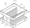
- FIG. 2 is a diagram schematically showing an exemplary configuration of the battery tray 100 according to an embodiment of the present disclosure.
- the battery tray 100 may include a housing 110, a receiving portion 120, a magnetic unit 130, a measuring unit 140, and a communication unit 150. Specifically, the battery tray 100 may transfer loaded batteries along a designated movement direction.
- the battery refers to an independent cell that has a negative electrode terminal and a positive electrode terminal and is physically separable.
- a lithium-ion cell or a lithium polymer cell may be considered a battery.
- the battery is explained as meaning one independent cell.
- the housing 110 may be configured so that other components of the battery tray 100 may be installed therein.
- the receiving portion 120, the magnetic unit 130, the measuring unit 140, and the communication unit 150 may be installed in the housing 110.
- the receiving portion 120 is installed inside the housing 110 and may be configured to allow a battery cell to be inserted.
- the receiving portion 120 may include a plurality of slots having opposing grooves. Also, one battery may be inserted into each slot.
- the receiving portion 120 may be installed inside the housing 110 in a vertical direction on the lower plate of the housing 110.
- each of the plurality of slots included in the receiving portion 120 may include grooves facing each other. Therefore, the produced battery may be inserted and fixed in each of the plurality of slots.
- the magnetic unit 130 may be configured so that at least one magnetic unit 130 is attached to the outer surface of the housing 110.
- the magnetic unit 130 may be configured to include a magnetic body. Additionally, the magnetic unit 130 may have a first polarity toward the outside of the housing 110 and a second polarity toward the inside of the housing 110. For example, the magnetic unit 130 may have an N pole toward the outside of the housing 110 and an S pole toward the inside of the housing 110.
- the magnetic units 130 may be configured so that the magnetic units 130 facing the outside of the housing 110 have the same polarities.
- the plurality of magnetic units 130 may have an N pole toward the outside of the housing 110 and an S pole toward the inside of the housing 110.
- 16 magnetic units 130 may be attached to the outer surface of the housing 110. Additionally, the 16 magnetic units 130 may have an N pole toward the outside of the housing 110 and an S pole toward the inside of the housing 110. In other words, when two or more battery trays 100 come close, a repulsive force may act between the battery trays 100.
- the measuring unit 140 may be configured to measure transfer information of the battery tray 100.
- the measuring unit 140 may measure various transfer information that can be measured while the battery tray 100 is being transferred.
- the measuring unit 140 may be configured to measure at least one of acceleration and angular velocity of the battery tray 100.
- the transfer information of the battery tray 100 measured by the measuring unit 140 may include acceleration information and angular velocity information of the battery tray 100.
- the communication unit 150 may be configured to output the transfer information measured by the measuring unit 140 to the outside.
- the communication unit 150 may be attached to the transferred battery tray 100. Therefore, the communication unit 150 may output the transfer information to the outside through wireless communication. Preferably, the communication unit 150 may output the transfer information to the outside using ultra wide band (UWB) wireless technology.
- UWB ultra wide band
- the battery tray 100 may further include a magnetic unit 130 to reduce the impact applied to the battery tray 100. Therefore, because the impact applied to the battery loaded on the battery tray 100 is alleviated, it is possible to prevent problems such as cracks from occurring in the battery during the transfer process.
- FIG. 3 is a diagram schematically showing a battery transfer system 10 according to another embodiment of the present disclosure.
- the battery transfer system 10 may include a battery tray 100, a transfer device 200, a communication device 300, and a control device 400.
- the battery tray 100 included in the battery transfer system 10 corresponds to the battery tray 100 described above, its description is omitted.
- the transfer device 200 may be configured to transfer the battery tray 100 along a preset transfer direction.
- the transfer device 200 may be pre-installed to transfer the battery tray 100 in a preset transfer direction. That is, the battery tray 100 may be introduced at one end of the transfer device 200, the battery tray 100 may be transferred along the preset transfer direction, and the battery tray 100 may be output at the other end of the transfer device 200.
- the communication device 300 may be connected to communicate with the communication unit 150.
- the communication device 300 may be connected to the communication unit 150 through wireless communication.
- the communication device 300 may be connected to the communication unit 150 to enable bi-directional communication.
- the communication device 300 may be configured to calculate the distance to the battery tray 100 using the communication time with the communication unit 150.
- the communication device 300 may transmit the first signal to the communication unit 150 of the battery tray 100.
- the communication unit 150 which has transmitted the first signal, may transmit the second signal to the communication device 300.
- the communication device 300 may calculate the distance from the battery tray 100 using the communication time from the time of transmitting the first signal to the time of receiving the second signal.
- the communication device 300 may calculate the distance to battery tray 100 by multiplying the speed of the first signal and the second signal and the communication time.
- a plurality of communication devices 300 may be provided.
- each of the plurality of communication devices 300 may calculate the distance to the battery tray 100.
- each of the plurality of communication devices 300 may transmit the distance information about the calculated distance to the control device 400.
- the control device 400 may be configured to determine the location of the battery tray 100 in the transfer device 200 based on the distance calculated by the communication device 300.
- control device 400 may determine the location of the battery tray 100 in the transfer device 200.
- the control device 400 may receive the distance information from the plurality of communication devices 300.
- the control device 400 may determine the location of the battery tray 100 based on the received plurality of distance information.
- the battery transfer system 10 includes three communication devices 300.
- the control device 400 may receive three distance information from three communication devices 300. Also, the control device 400 may determine the location of the battery tray 100 by combining the three received distance information.
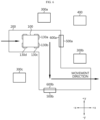
- FIGS. 4 to 7 are diagrams schematically showing exemplary configurations of the battery transfer system 10 according to another embodiment of the present disclosure.
- the embodiment of FIG. 4 is a diagram schematically showing the transfer device 200, the communication device 300, and the control device 400.
- the embodiment of FIG. 5 is a diagram further illustrating the stopper device 500 in the embodiment of FIG. 4 .
- the embodiment of FIG. 6 is a diagram further illustrating the magnetic device 600 in the embodiment of FIG. 5 .
- the embodiment of FIG. 7 is a diagram further illustrating the battery tray 100 in the embodiment of FIG. 6 .
- the battery transfer system 10 may further include a stopper device 500 and a magnetic device 600.
- the stopper device 500 may be fixedly coupled to the transfer device 200 to stop the transfer of the battery tray 100.
- the stopper device 500 may be fixedly coupled to the transfer device 200 at a point where the movement direction of the battery tray 100 by the transfer device 200 is changed. For example, when the movement direction of the battery tray 100 changes, the battery tray 100 may separate from the transfer device 200. Therefore, in order to prevent the battery tray 100 from being separated, the stopper device 500 may be fixedly coupled at the point where the movement direction of the transfer device 200 changes.
- the movement direction may start in the +x direction, change to the -y direction, and then change to the +x direction again. That is, the movement direction may be changed in the z1 section and the z2 section.
- the battery tray 100 may separate from the transfer device 200. Likewise, if the battery tray 100 continues to move in the -y direction in the z2 section, the battery tray 100 may separate from the transfer device 200. Therefore, in order to prevent the battery tray 100 from being separated, the stopper device 500 may be installed at the point where the movement direction changes, as shown in the embodiment of FIG. 5 .
- the first stopper device 500a may prevent the battery tray 100 from separating in the +x direction.
- the second stopper device 500b may prevent battery tray 100 from separating in the -y direction.
- the magnetic device 600 is attached to the outer surface of the stopper device 500 and may be configured to exhibit magnetism depending on the operation state.
- shock may be applied to the battery tray 100 and the battery.
- the magnetic device 600 may be attached to the stopper device 500.
- the magnetic device 600 may be attached to the outer surface of the stopper device 500 to correspond to the movement direction of the battery tray 100.
- the first magnetic device 600a may be attached to the outer surface of the first stopper device 500a.
- the second magnetic device 600b may be attached to the outer surface of the second stopper device 500b.
- the magnetic device 600 may be configured so that the polarity facing the battery tray 100 is the same as the polarity of the magnetic unit 130 facing the outside of the housing 110.
- a repulsive force may act between the magnetic unit 130 of the battery tray 100 and the magnetic device 600. The impact between the battery tray 100 and the magnetic device 600 may be reduced by this repulsive force.
- the polarity of the magnetic unit 130 facing the outside of the housing 110 is the N pole.
- the polarity facing the -x direction may be the N pole.
- the polarity facing the +y direction in the second magnetic device 600b may be the N pole.
- the first magnetic unit 130a, the second magnetic unit 130b and the first magnetic device 600a may become closer.
- a repulsive force may act between the first magnetic unit 130a and the first magnetic device 600a and between the second magnetic unit 130b and the first magnetic device 600a. Therefore, the impact amount of the battery tray 100 and the first magnetic device 600a may be reduced.
- the third magnetic unit 130c, the fourth magnetic unit 130d and the second magnetic device 600b may get closer.
- a repulsive force may act between the third magnetic unit 130c and the second magnetic device 600b and between the fourth magnetic unit 130d and the second magnetic device 600b. Therefore, the impact amount of the battery tray 100 and the second magnetic device 600b may be reduced.
- the battery transfer system 10 has the advantage of effectively reducing the impact applied to the battery tray 100 while guiding the movement direction of the battery tray 100 so that the battery tray 100 does not separate from the transfer device 200. Therefore, in the process of transferring the battery through the battery tray 100, the possibility of battery defects due to impact may be significantly reduced.
- control device 400 controls the operation state of the magnetic device 600
- the control device 400 controls the operation state of the magnetic device 600
- the first communication device 300a, the second communication device 300b, and the third communication device 300c may be connected to communicate with the communication unit 150 of the battery tray 100.
- each of the first communication device 300a, the second communication device 300b, and the third communication device 300c may calculate the distance from the battery tray 100.
- the distance between the first communication device 300a and the battery tray 100 may be R1
- the distance between the second communication device 300b and the battery tray 100 may be R2
- the distance between the third communication device 300c and the battery tray 100 may be R3.
- the control device 400 may determine the location of the battery tray 100 in the transfer device 200 based on R1, R2, and R3. Specifically, the control device 400 may determine the location of the battery tray 100 according to the trilateration method using the location of the first communication device 300a and R1, the location of the second communication device 300b and R2, and the location of the third communication device 300c and R3.
- the control device 400 may be configured to control the operation state of the magnetic device 600 based on the location of the battery tray 100 and the location of the stopper device 500.
- control device 400 may be configured to control the operation state of the magnetic device 600 so that the magnetic device 600 exhibits magnetism when the distance between the location of the battery tray 100 and the location of the stopper device 500 is less than or equal to a preset reference distance.
- control device 400 may control the operation state of the magnetic device 600 so that the magnetic device 600 exhibits magnetism when the distance between the location of the battery tray 100 and the location of the stopper device 500 reaches the preset reference distance.
- the location of the stopper device 500 and the location of the magnetic device 600 are assumed to be substantially the same.
- control device 400 may compare the calculated distance (distance between the battery tray 100 and the stopper device 500) with a preset reference distance.
- the reference distance may be preset to a minimum distance at which the magnetic force by the magnetic device 600 may be maximized before the battery tray 100 reaches the magnetic device 600 when the control device 400 controls the operation of the magnetic device 600. That is, the reference distance may be set in advance for the transfer device 200 based on a preset unit transfer distance (e.g., transfer distance per second) and the time from the time point when the operation of the magnetic device 600 is changed to the time point when the maximum magnetic force is expressed.
- a preset unit transfer distance e.g., transfer distance per second
- the control device 400 may change the operation state of the first magnetic device 600a so that the first magnetic device 600a exhibits magnetism.
- the control device 400 may control the operation state of the magnetic device 600 into a turn-on state or a turn-off state.
- the turn-on state means a state in which current flows through the magnetic device 600 and the magnetic device 600 exhibits magnetism according to the current flow.
- the turn-off state means a state in which no current flows to the magnetic device 600 and the magnetic device 600 does not exhibit magnetism.
- the current direction in the turn-on state may be preset to a direction in which the polarity of the magnetic device 600 facing the battery tray 100 is the same as the polarity of the magnetic unit 130 facing the outside of the housing 110.
- the polarity of the magnetic unit 130 facing the outside of the housing 110 is the N pole
- the polarity of the magnetic unit 130 facing the inside of the housing 110 is the S pole.
- the current direction in the turn-on state may be set in advance so that the polarity of the magnetic device 600 facing the battery tray 100 is the N pole, and the polarity of the magnetic device 600 facing the stopper device 500 is the S pole.
- control device 400 may control the operation state of the magnetic device 600 to the turn-on state if the distance between the battery tray 100 and the stopper device 500 is less than or equal to the reference distance.
- the battery transfer system 10 prevents unnecessary resource consumption and may reduce the impact amount applied to the battery tray 100. Therefore, the battery may be transferred safely and efficiently.
- the communication device 300 may be configured to receive the transfer information from the communication unit 150 and calculate the impact amount applied to the battery tray 100 based on the received transfer information.
- the communication device 300 may calculate the impact amount applied to the battery tray 100 based on at least one of the acceleration information and the angular velocity information received from the communication unit 150. Preferably, the communication device 300 may calculate the impact amount applied to the battery tray 100 based on the acceleration information and the angular velocity information.
- the control device 400 may be configured to change the communication period between the communication unit 150 and the communication device 300 and the measurement period of the measuring unit 140 when the impact amount calculated by the communication device 300 is greater than or equal to a preset threshold impact amount.
- the threshold impact amount may be set in advance to an impact amount that may cause a defect in the battery. For example, if the impact amount is more than or equal to the threshold impact amount, cracks or the like may occur in the battery.
- the control device 400 may change the communication period and the measurement period to more precisely detect the location of the battery tray 100.
- the control device 400 may change the communication period so that the communication period between the communication unit 150 and the communication device 300 is shortened, and change the measurement period so that the measurement period of the measuring unit 140 is shortened.
- the transfer information for the battery tray 100 may be measured more frequently according to the shortened measurement period, and the transfer information may be transmitted to communication device 300 more quickly than before according to the shortened communication period. Because the control device 400 may receive the distance information to the battery tray 100 from the communication device 300 more quickly than before, the control device 400 may determine the location of the battery tray 100 in the transfer device 200 in a shorter cycle than before.
- control device 400 may be configured to further change the communication intensity of the communication unit 150 if the calculated impact amount is greater than or equal to the threshold impact amount.
- the battery transfer system 10 may further include an alarm device 700.
- the alarm device 700 may be configured to receive a signal output from the communication unit 150, and to emit light or blink when the intensity of the received signal is greater than or equal to a preset threshold intensity. Specifically, if the calculated impact amount is more than or equal to the threshold impact amount, the control device 400 may change the communication intensity of the communication unit 150 to be more than or equal to the threshold intensity. That is, a signal having an intensity greater than or equal to the threshold intensity may be output from the communication unit 150. Accordingly, the user or worker may easily check whether the battery tray 100 transferred through the transfer device 200 has a defect by checking the alarm device 700.
Landscapes
- Engineering & Computer Science (AREA)
- Chemical & Material Sciences (AREA)
- Chemical Kinetics & Catalysis (AREA)
- Electrochemistry (AREA)
- General Chemical & Material Sciences (AREA)
- Mechanical Engineering (AREA)
- Manufacturing & Machinery (AREA)
- Microelectronics & Electronic Packaging (AREA)
- Business, Economics & Management (AREA)
- Emergency Management (AREA)
- Physics & Mathematics (AREA)
- General Physics & Mathematics (AREA)
- Battery Mounting, Suspending (AREA)
- Non-Mechanical Conveyors (AREA)
- Control Of Conveyors (AREA)
Abstract
Description
- The present application claims priority to
Korean Patent Application No. 10-2022-0185679 filed on December 27, 2022 - The present disclosure relates to a battery tray and a battery transfer system, and more specifically, to a battery tray and a battery transfer system that may safely transfer produced batteries.
- Recently, the demand for portable electronic products such as notebook computers, video cameras and portable telephones has increased sharply, and electric vehicles, energy storage batteries, robots, satellites and the like have been developed in earnest. Accordingly, high-performance batteries allowing repeated charging and discharging are being actively studied.
- Batteries commercially available at present include nickel-cadmium batteries, nickel hydrogen batteries, nickel-zinc batteries, lithium batteries and the like. Among them, the lithium batteries are in the limelight since they have almost no memory effect compared to nickel-based batteries and also have very low self-charging rate and high energy density.
- After these batteries are produced, they are placed in a battery tray, and the battery tray may be moved through a transfer device such as a conveyor. If shock is applied to the battery tray during the battery transfer process, problems such as cracks may occur in the produced battery. For example, shock may occur between the battery trays, and shock may occur between the stopper device provided on the conveyor and the battery tray.
- Therefore, it is necessary to develop technology that may safely transfer batteries by reducing the shock generated during the transfer process of produced batteries.
- The present disclosure is designed to solve the problems of the related art, and therefore the present disclosure is directed to providing a battery tray and a battery transfer system that may safely transfer batteries.
- These and other objects and advantages of the present disclosure may be understood from the following detailed description and will become more fully apparent from the exemplary embodiments of the present disclosure. Also, it will be easily understood that the objects and advantages of the present disclosure may be realized by the means shown in the appended claims and combinations thereof.
- A battery tray according to one aspect of the present disclosure may comprise a housing; a receiving portion installed inside the housing and configured to allow a battery cell to be inserted; at least one magnetic unit configured to be attached to an outer surface of the housing; a measuring unit configured to measure transfer information of the battery tray; and a communication unit configured to output the transfer information measured by the measuring unit to the outside.
- When a plurality of magnetic units are attached to the outer surface of the housing, the magnetic units may be configured so that the magnetic units facing the outside of the housing have the same polarities.
- A battery transfer system according to another aspect of the present disclosure may comprise the battery tray according to one aspect of the present disclosure; a transfer device configured to transfer the battery tray along a preset transfer direction; a communication device connected to enable communication with the communication unit and configured to calculate a distance to the battery tray using communication time with the communication unit; and a control device configured to determine a location of the battery tray in the transfer device based on the distance calculated by the communication device.
- A battery transfer system according to still another aspect of the present disclosure may further comprise a stopper device fixedly coupled to the transfer device to stop the transfer of the battery tray; and a magnetic device attached to an outer surface of the stopper device and configured to exhibit magnetism depending on an operation state.
- The magnetic device may be configured so that a polarity of the magnetic device toward the battery tray is the same as a polarity of the magnetic unit toward the outside of the housing.
- The control device may be configured to control the operation state of the magnetic device based on the location of the battery tray and a location of the stopper device.
- The control device may be configured to control the operation state of the magnetic device so that the magnetic device exhibits magnetism when a distance between the location of the battery tray and the location of the stopper device is less than or equal to a preset reference distance.
- The stopper device may be fixedly coupled to the transfer device at a point where a movement direction of the battery tray by the transfer device changes.
- The communication device may be configured to receive the transfer information from the communication unit and calculate an impact amount applied to the battery tray based on the received transfer information.
- The control device may be configured to change a communication period between the communication unit and the communication device and a measurement period of the measuring unit when the impact amount calculated by the communication device is more than or equal to a preset threshold impact amount.
- The control device may be configured to further change a communication intensity of the communication unit when the calculated impact amount is more than or equal to the threshold impact amount.
- According to one aspect of the present disclosure, because the battery may be safely transferred, it is possible to prevent defects such as cracks from occurring in the battery during the transfer process.
- The effects of the present disclosure are not limited to the effects mentioned above, and other effects not mentioned will be clearly understood by those skilled in the art from the description of the claims.
- The accompanying drawings illustrate a preferred embodiment of the present disclosure and together with the foregoing disclosure, serve to provide further understanding of the technical features of the present disclosure, and thus, the present disclosure is not construed as being limited to the drawing.
-
FIG. 1 is a diagram schematically showing a battery tray according to an embodiment of the present disclosure. -
FIG. 2 is a diagram schematically showing an exemplary configuration of the battery tray according to an embodiment of the present disclosure. -
FIG. 3 is a diagram schematically showing a battery transfer system according to another embodiment of the present disclosure. -
FIGS. 4 to 7 are diagrams schematically showing exemplary configurations of the battery transfer system according to another embodiment of the present disclosure. - It should be understood that the terms used in the specification and the appended claims should not be construed as limited to general and dictionary meanings, but interpreted based on the meanings and concepts corresponding to technical aspects of the present disclosure on the basis of the principle that the inventor is allowed to define terms appropriately for the best explanation.
- Therefore, the description proposed herein is just a preferable example for the purpose of illustrations only, not intended to limit the scope of the disclosure, so it should be understood that other equivalents and modifications could be made thereto without departing from the scope of the disclosure.
- Additionally, in describing the present disclosure, when it is deemed that a detailed description of relevant known elements or functions renders the key subject matter of the present disclosure ambiguous, the detailed description is omitted herein.
- The terms including the ordinal number such as "first", "second" and the like, may be used to distinguish one element from another among various elements, but not intended to limit the elements by the terms.
- Throughout the specification, when a portion is referred to as "comprising" or "including" any element, it means that the portion may include other elements further, without excluding other elements, unless specifically stated otherwise.
- In addition, throughout the specification, when a portion is referred to as being "connected" to another portion, it is not limited to the case that they are "directly connected", but it also includes the case where they are "indirectly connected" with another element being interposed between them.
- Hereinafter, a preferred embodiment of the present disclosure will be described in detail with reference to the accompanying drawings.
-
FIG. 1 is a diagram schematically showing abattery tray 100 according to an embodiment of the present disclosure.FIG. 2 is a diagram schematically showing an exemplary configuration of thebattery tray 100 according to an embodiment of the present disclosure. - Referring to
FIG. 1 , thebattery tray 100 may include ahousing 110, a receivingportion 120, amagnetic unit 130, ameasuring unit 140, and acommunication unit 150. Specifically, thebattery tray 100 may transfer loaded batteries along a designated movement direction. - Here, the battery refers to an independent cell that has a negative electrode terminal and a positive electrode terminal and is physically separable. As an example, a lithium-ion cell or a lithium polymer cell may be considered a battery. Hereinafter, for convenience of explanation, the battery is explained as meaning one independent cell.
- The
housing 110 may be configured so that other components of thebattery tray 100 may be installed therein. For example, thereceiving portion 120, themagnetic unit 130, themeasuring unit 140, and thecommunication unit 150 may be installed in thehousing 110. - The
receiving portion 120 is installed inside thehousing 110 and may be configured to allow a battery cell to be inserted. - Specifically, the
receiving portion 120 may include a plurality of slots having opposing grooves. Also, one battery may be inserted into each slot. - For example, in the embodiment of
FIG. 2 , thereceiving portion 120 may be installed inside thehousing 110 in a vertical direction on the lower plate of thehousing 110. Additionally, each of the plurality of slots included in thereceiving portion 120 may include grooves facing each other. Therefore, the produced battery may be inserted and fixed in each of the plurality of slots. - The
magnetic unit 130 may be configured so that at least onemagnetic unit 130 is attached to the outer surface of thehousing 110. - Specifically, the
magnetic unit 130 may be configured to include a magnetic body. Additionally, themagnetic unit 130 may have a first polarity toward the outside of thehousing 110 and a second polarity toward the inside of thehousing 110. For example, themagnetic unit 130 may have an N pole toward the outside of thehousing 110 and an S pole toward the inside of thehousing 110. - Preferably, when a plurality of
magnetic units 130 are attached to the outer surface of thehousing 110, themagnetic units 130 may be configured so that themagnetic units 130 facing the outside of thehousing 110 have the same polarities. For example, the plurality ofmagnetic units 130 may have an N pole toward the outside of thehousing 110 and an S pole toward the inside of thehousing 110. - In the embodiment of
FIG. 2 , 16magnetic units 130 may be attached to the outer surface of thehousing 110. Additionally, the 16magnetic units 130 may have an N pole toward the outside of thehousing 110 and an S pole toward the inside of thehousing 110. In other words, when two ormore battery trays 100 come close, a repulsive force may act between thebattery trays 100. - The measuring
unit 140 may be configured to measure transfer information of thebattery tray 100. - Specifically, the measuring
unit 140 may measure various transfer information that can be measured while thebattery tray 100 is being transferred. Preferably, the measuringunit 140 may be configured to measure at least one of acceleration and angular velocity of thebattery tray 100. For example, the transfer information of thebattery tray 100 measured by the measuringunit 140 may include acceleration information and angular velocity information of thebattery tray 100. - The
communication unit 150 may be configured to output the transfer information measured by the measuringunit 140 to the outside. - For example, the
communication unit 150 may be attached to the transferredbattery tray 100. Therefore, thecommunication unit 150 may output the transfer information to the outside through wireless communication. Preferably, thecommunication unit 150 may output the transfer information to the outside using ultra wide band (UWB) wireless technology. - The
battery tray 100 according to an embodiment of the present disclosure may further include amagnetic unit 130 to reduce the impact applied to thebattery tray 100. Therefore, because the impact applied to the battery loaded on thebattery tray 100 is alleviated, it is possible to prevent problems such as cracks from occurring in the battery during the transfer process. -
FIG. 3 is a diagram schematically showing abattery transfer system 10 according to another embodiment of the present disclosure. - Referring to
FIG. 3 , thebattery transfer system 10 may include abattery tray 100, atransfer device 200, acommunication device 300, and acontrol device 400. - Since the
battery tray 100 included in thebattery transfer system 10 corresponds to thebattery tray 100 described above, its description is omitted. - The
transfer device 200 may be configured to transfer thebattery tray 100 along a preset transfer direction. - Specifically, the
transfer device 200 may be pre-installed to transfer thebattery tray 100 in a preset transfer direction. That is, thebattery tray 100 may be introduced at one end of thetransfer device 200, thebattery tray 100 may be transferred along the preset transfer direction, and thebattery tray 100 may be output at the other end of thetransfer device 200. - For example, the
transfer device 200 may be a conveyor capable of transferring thebattery tray 100. After thebattery tray 100 is introduced into thetransfer device 200, thebattery tray 100 may be moved along the transfer direction set by thetransfer device 200. - The
communication device 300 may be connected to communicate with thecommunication unit 150. - For example, the
communication device 300 may be connected to thecommunication unit 150 through wireless communication. Preferably, thecommunication device 300 may be connected to thecommunication unit 150 to enable bi-directional communication. - The
communication device 300 may be configured to calculate the distance to thebattery tray 100 using the communication time with thecommunication unit 150. - For example, the
communication device 300 may transmit the first signal to thecommunication unit 150 of thebattery tray 100. Thecommunication unit 150, which has transmitted the first signal, may transmit the second signal to thecommunication device 300. Thecommunication device 300 may calculate the distance from thebattery tray 100 using the communication time from the time of transmitting the first signal to the time of receiving the second signal. Thecommunication device 300 may calculate the distance tobattery tray 100 by multiplying the speed of the first signal and the second signal and the communication time. - Preferably, a plurality of
communication devices 300 may be provided. For example, each of the plurality ofcommunication devices 300 may calculate the distance to thebattery tray 100. Also, each of the plurality ofcommunication devices 300 may transmit the distance information about the calculated distance to thecontrol device 400. - The
control device 400 may be configured to determine the location of thebattery tray 100 in thetransfer device 200 based on the distance calculated by thecommunication device 300. - Specifically, the
control device 400 may determine the location of thebattery tray 100 in thetransfer device 200. Preferably, thecontrol device 400 may receive the distance information from the plurality ofcommunication devices 300. Also, thecontrol device 400 may determine the location of thebattery tray 100 based on the received plurality of distance information. - For example, it is assumed that the
battery transfer system 10 includes threecommunication devices 300. Thecontrol device 400 may receive three distance information from threecommunication devices 300. Also, thecontrol device 400 may determine the location of thebattery tray 100 by combining the three received distance information. -
FIGS. 4 to 7 are diagrams schematically showing exemplary configurations of thebattery transfer system 10 according to another embodiment of the present disclosure. Specifically, the embodiment ofFIG. 4 is a diagram schematically showing thetransfer device 200, thecommunication device 300, and thecontrol device 400. The embodiment ofFIG. 5 is a diagram further illustrating thestopper device 500 in the embodiment ofFIG. 4 . The embodiment ofFIG. 6 is a diagram further illustrating themagnetic device 600 in the embodiment ofFIG. 5 . The embodiment ofFIG. 7 is a diagram further illustrating thebattery tray 100 in the embodiment ofFIG. 6 . - Referring to
FIG. 3 , thebattery transfer system 10 may further include astopper device 500 and amagnetic device 600. - The
stopper device 500 may be fixedly coupled to thetransfer device 200 to stop the transfer of thebattery tray 100. - Specifically, the
stopper device 500 may be fixedly coupled to thetransfer device 200 at a point where the movement direction of thebattery tray 100 by thetransfer device 200 is changed. For example, when the movement direction of thebattery tray 100 changes, thebattery tray 100 may separate from thetransfer device 200. Therefore, in order to prevent thebattery tray 100 from being separated, thestopper device 500 may be fixedly coupled at the point where the movement direction of thetransfer device 200 changes. - For example, in the embodiment of
FIG. 4 , the movement direction may start in the +x direction, change to the -y direction, and then change to the +x direction again. That is, the movement direction may be changed in the z1 section and the z2 section. - If the
battery tray 100 continues to move in the +x direction in the z1 section, thebattery tray 100 may separate from thetransfer device 200. Likewise, if thebattery tray 100 continues to move in the -y direction in the z2 section, thebattery tray 100 may separate from thetransfer device 200. Therefore, in order to prevent thebattery tray 100 from being separated, thestopper device 500 may be installed at the point where the movement direction changes, as shown in the embodiment ofFIG. 5 . - In the embodiment of
FIG. 5 , thefirst stopper device 500a may prevent thebattery tray 100 from separating in the +x direction. Thesecond stopper device 500b may preventbattery tray 100 from separating in the -y direction. - The
magnetic device 600 is attached to the outer surface of thestopper device 500 and may be configured to exhibit magnetism depending on the operation state. - In the embodiment of
FIG. 5 , when thebattery tray 100, which is transferred along the movement direction, collides with thefirst stopper device 500a or thesecond stopper device 500b, shock may be applied to thebattery tray 100 and the battery. In other words, separation of thebattery tray 100 may be prevented, but shock may be applied to the battery, so battery defects may occur. Therefore, in order to alleviate the impact applied to thebattery tray 100, themagnetic device 600 may be attached to thestopper device 500. - Specifically, the
magnetic device 600 may be attached to the outer surface of thestopper device 500 to correspond to the movement direction of thebattery tray 100. In the embodiment ofFIG. 6 , the firstmagnetic device 600a may be attached to the outer surface of thefirst stopper device 500a. Additionally, the secondmagnetic device 600b may be attached to the outer surface of thesecond stopper device 500b. - Preferably, the
magnetic device 600 may be configured so that the polarity facing thebattery tray 100 is the same as the polarity of themagnetic unit 130 facing the outside of thehousing 110. For example, when thebattery tray 100 approaches themagnetic device 600 with magnetism, a repulsive force may act between themagnetic unit 130 of thebattery tray 100 and themagnetic device 600. The impact between thebattery tray 100 and themagnetic device 600 may be reduced by this repulsive force. - In the embodiment of
FIG. 6 , it is assumed that the polarity of themagnetic unit 130 facing the outside of thehousing 110 is the N pole. In the firstmagnetic device 600a, the polarity facing the -x direction may be the N pole. Additionally, the polarity facing the +y direction in the secondmagnetic device 600b may be the N pole. - For example, when the
battery tray 100 moves in the +x direction and approaches thefirst stopper device 500a, the firstmagnetic unit 130a, the secondmagnetic unit 130b and the firstmagnetic device 600a may become closer. In this case, a repulsive force may act between the firstmagnetic unit 130a and the firstmagnetic device 600a and between the secondmagnetic unit 130b and the firstmagnetic device 600a. Therefore, the impact amount of thebattery tray 100 and the firstmagnetic device 600a may be reduced. - As another example, when the
battery tray 100 moves in the -y direction and gets closer to thesecond stopper device 500b, the thirdmagnetic unit 130c, the fourthmagnetic unit 130d and the secondmagnetic device 600b may get closer. In this case, a repulsive force may act between the thirdmagnetic unit 130c and the secondmagnetic device 600b and between the fourthmagnetic unit 130d and the secondmagnetic device 600b. Therefore, the impact amount of thebattery tray 100 and the secondmagnetic device 600b may be reduced. - The
battery transfer system 10 has the advantage of effectively reducing the impact applied to thebattery tray 100 while guiding the movement direction of thebattery tray 100 so that thebattery tray 100 does not separate from thetransfer device 200. Therefore, in the process of transferring the battery through thebattery tray 100, the possibility of battery defects due to impact may be significantly reduced. - Below, an embodiment in which the
control device 400 controls the operation state of themagnetic device 600 will be described using the embodiment ofFIG. 7 . - In the embodiment of
FIG. 7 , thefirst communication device 300a, thesecond communication device 300b, and thethird communication device 300c may be connected to communicate with thecommunication unit 150 of thebattery tray 100. In addition, each of thefirst communication device 300a, thesecond communication device 300b, and thethird communication device 300c may calculate the distance from thebattery tray 100. The distance between thefirst communication device 300a and thebattery tray 100 may be R1, the distance between thesecond communication device 300b and thebattery tray 100 may be R2, and the distance between thethird communication device 300c and thebattery tray 100 may be R3. - The
control device 400 may determine the location of thebattery tray 100 in thetransfer device 200 based on R1, R2, and R3. Specifically, thecontrol device 400 may determine the location of thebattery tray 100 according to the trilateration method using the location of thefirst communication device 300a and R1, the location of thesecond communication device 300b and R2, and the location of thethird communication device 300c and R3. - The
control device 400 may be configured to control the operation state of themagnetic device 600 based on the location of thebattery tray 100 and the location of thestopper device 500. - Specifically, the
control device 400 may be configured to control the operation state of themagnetic device 600 so that themagnetic device 600 exhibits magnetism when the distance between the location of thebattery tray 100 and the location of thestopper device 500 is less than or equal to a preset reference distance. Preferably, thecontrol device 400 may control the operation state of themagnetic device 600 so that themagnetic device 600 exhibits magnetism when the distance between the location of thebattery tray 100 and the location of thestopper device 500 reaches the preset reference distance. - In the following, since the
magnetic device 600 is attached to the outer surface of thestopper device 500, the location of thestopper device 500 and the location of themagnetic device 600 are assumed to be substantially the same. - Specifically, the
control device 400 may calculate the distance between the determined location of thebattery tray 100 and the location where thestopper device 500 is installed. - For example, in the embodiment of
FIG. 7 , thecontrol device 400 may calculate the distance between the location of thebattery tray 100 and thefirst stopper device 500a as R4. Preferably, since thebattery tray 100 is moving in the +x direction toward thefirst stopper device 500a, the distance between thebattery tray 100 and thesecond stopper device 500b may not be calculated. In other words, thecontrol device 400 may calculate the distance between thestopper device 500 and thebattery tray 100 at the closest location in the direction toward which thebattery tray 100 is heading. - Additionally, the
control device 400 may compare the calculated distance (distance between thebattery tray 100 and the stopper device 500) with a preset reference distance. Here, the reference distance may be preset to a minimum distance at which the magnetic force by themagnetic device 600 may be maximized before thebattery tray 100 reaches themagnetic device 600 when thecontrol device 400 controls the operation of themagnetic device 600. That is, the reference distance may be set in advance for thetransfer device 200 based on a preset unit transfer distance (e.g., transfer distance per second) and the time from the time point when the operation of themagnetic device 600 is changed to the time point when the maximum magnetic force is expressed. - For example, in the embodiment of
FIG. 7 , when R4 reaches the preset reference distance, thecontrol device 400 may change the operation state of the firstmagnetic device 600a so that the firstmagnetic device 600a exhibits magnetism. - The
control device 400 may control the operation state of themagnetic device 600 into a turn-on state or a turn-off state. The turn-on state means a state in which current flows through themagnetic device 600 and themagnetic device 600 exhibits magnetism according to the current flow. The turn-off state means a state in which no current flows to themagnetic device 600 and themagnetic device 600 does not exhibit magnetism. - Here, the current direction in the turn-on state may be preset to a direction in which the polarity of the
magnetic device 600 facing thebattery tray 100 is the same as the polarity of themagnetic unit 130 facing the outside of thehousing 110. For example, it is assumed that the polarity of themagnetic unit 130 facing the outside of thehousing 110 is the N pole, and the polarity of themagnetic unit 130 facing the inside of thehousing 110 is the S pole. The current direction in the turn-on state may be set in advance so that the polarity of themagnetic device 600 facing thebattery tray 100 is the N pole, and the polarity of themagnetic device 600 facing thestopper device 500 is the S pole. - Because unnecessary energy is consumed if the state of the
magnetic device 600 remains in the turn-on state even though thebattery tray 100 has not reached thestopper device 500, thecontrol device 400 may control the operation state of themagnetic device 600 to the turn-on state if the distance between thebattery tray 100 and thestopper device 500 is less than or equal to the reference distance. - The
battery transfer system 10 prevents unnecessary resource consumption and may reduce the impact amount applied to thebattery tray 100. Therefore, the battery may be transferred safely and efficiently. - The
communication device 300 may be configured to receive the transfer information from thecommunication unit 150 and calculate the impact amount applied to thebattery tray 100 based on the received transfer information. - Specifically, the
communication device 300 may calculate the impact amount applied to thebattery tray 100 based on at least one of the acceleration information and the angular velocity information received from thecommunication unit 150. Preferably, thecommunication device 300 may calculate the impact amount applied to thebattery tray 100 based on the acceleration information and the angular velocity information. - Additionally, the
communication device 300 may transmit the impact amount information about the calculated impact amount to thecontrol device 400. - The
control device 400 may be configured to change the communication period between thecommunication unit 150 and thecommunication device 300 and the measurement period of the measuringunit 140 when the impact amount calculated by thecommunication device 300 is greater than or equal to a preset threshold impact amount. - Specifically, the threshold impact amount may be set in advance to an impact amount that may cause a defect in the battery. For example, if the impact amount is more than or equal to the threshold impact amount, cracks or the like may occur in the battery.
- If the calculated impact amount is more than or equal to the threshold impact amount, the
control device 400 may change the communication period and the measurement period to more precisely detect the location of thebattery tray 100. Preferably, thecontrol device 400 may change the communication period so that the communication period between thecommunication unit 150 and thecommunication device 300 is shortened, and change the measurement period so that the measurement period of the measuringunit 140 is shortened. In other words, the transfer information for thebattery tray 100 may be measured more frequently according to the shortened measurement period, and the transfer information may be transmitted tocommunication device 300 more quickly than before according to the shortened communication period. Because thecontrol device 400 may receive the distance information to thebattery tray 100 from thecommunication device 300 more quickly than before, thecontrol device 400 may determine the location of thebattery tray 100 in thetransfer device 200 in a shorter cycle than before. - Additionally, the
control device 400 may be configured to further change the communication intensity of thecommunication unit 150 if the calculated impact amount is greater than or equal to the threshold impact amount. - Referring to
FIG. 3 , thebattery transfer system 10 may further include analarm device 700. - The
alarm device 700 may be configured to receive a signal output from thecommunication unit 150, and to emit light or blink when the intensity of the received signal is greater than or equal to a preset threshold intensity. Specifically, if the calculated impact amount is more than or equal to the threshold impact amount, thecontrol device 400 may change the communication intensity of thecommunication unit 150 to be more than or equal to the threshold intensity. That is, a signal having an intensity greater than or equal to the threshold intensity may be output from thecommunication unit 150. Accordingly, the user or worker may easily check whether thebattery tray 100 transferred through thetransfer device 200 has a defect by checking thealarm device 700. - The present disclosure has been described in detail. However, it should be understood that the detailed description and specific examples, while indicating preferred embodiments of the disclosure, are given by way of illustration only, since various changes and modifications within the scope of the disclosure will become apparent to those skilled in the art from this detailed description.
- Additionally, many substitutions, modifications and changes may be made to the present disclosure described hereinabove by those skilled in the art without departing from the technical aspects of the present disclosure, and the present disclosure is not limited to the above-described embodiments and the accompanying drawings, and each embodiment may be selectively combined in part or in whole to allow various modifications.
-
- 10: battery transfer system
- 100: battery tray
- 110: housing
- 120: receiving portion
- 130: magnetic unit
- 140: measuring unit
- 150: communication unit
- 200: transfer device
- 300: communication device
- 400: control device
- 500: stopper device
- 600: magnetic device
- 700: alarm device
Claims (10)
- A battery tray, comprising:a housing;a receiving portion installed inside the housing and configured to allow a battery cell to be inserted;at least one magnetic unit configured to be attached to an outer surface of the housing;a measuring unit configured to measure transfer information of the battery tray; anda communication unit configured to output the transfer information measured by the measuring unit to the outside.
- The battery tray according to claim 1,
wherein when a plurality of magnetic units are attached to the outer surface of the housing, the magnetic units are configured so that the magnetic units facing the outside of the housing have the same polarities. - A battery transfer system, comprising:the battery tray according to claim 1 or 2;a transfer device configured to transfer the battery tray along a preset transfer direction;a communication device connected to enable communication with the communication unit and configured to calculate a distance to the battery tray using communication time with the communication unit; anda control device configured to determine a location of the battery tray in the transfer device based on the distance calculated by the communication device.
- The battery transfer system according to claim 3, further comprising:a stopper device fixedly coupled to the transfer device to stop the transfer of the battery tray; anda magnetic device attached to an outer surface of the stopper device and configured to exhibit magnetism depending on an operation state.
- The battery transfer system according to claim 4,
wherein the magnetic device is configured so that a polarity of the magnetic device toward the battery tray is the same as a polarity of the magnetic unit toward the outside of the housing. - The battery transfer system according to claim 4,
wherein the control device is configured to control the operation state of the magnetic device based on the location of the battery tray and a location of the stopper device. - The battery transfer system according to claim 6,
wherein the control device is configured to control the operation state of the magnetic device so that the magnetic device exhibits magnetism when a distance between the location of the battery tray and the location of the stopper device is less than or equal to a preset reference distance. - The battery transfer system according to claim 4,
wherein the stopper device is fixedly coupled to the transfer device at a point where a movement direction of the battery tray by the transfer device changes. - The battery transfer system according to claim 3,wherein the communication device is configured to receive the transfer information from the communication unit and calculate an impact amount applied to the battery tray based on the received transfer information, andwherein the control device is configured to change a communication period between the communication unit and the communication device and a measurement period of the measuring unit when the impact amount calculated by the communication device is more than or equal to a preset threshold impact amount.
- The battery transfer system according to claim 9,
wherein the control device is configured to further change a communication intensity of the communication unit when the calculated impact amount is more than or equal to the threshold impact amount.
Applications Claiming Priority (2)
| Application Number | Priority Date | Filing Date | Title |
|---|---|---|---|
| KR1020220185679A KR20240103471A (en) | 2022-12-27 | 2022-12-27 | Battery tray and system for transporing battery |
| PCT/KR2023/020688 WO2024144024A1 (en) | 2022-12-27 | 2023-12-14 | Battery tray and battery transfer system |
Publications (2)
| Publication Number | Publication Date |
|---|---|
| EP4574705A1 true EP4574705A1 (en) | 2025-06-25 |
| EP4574705A4 EP4574705A4 (en) | 2026-03-18 |
Family
ID=91718498
Family Applications (1)
| Application Number | Title | Priority Date | Filing Date |
|---|---|---|---|
| EP23912699.8A Pending EP4574705A4 (en) | 2022-12-27 | 2023-12-14 | BATTERY COMPARTMENT AND BATTERY TRANSFER SYSTEM |
Country Status (6)
| Country | Link |
|---|---|
| US (1) | US20260058279A1 (en) |
| EP (1) | EP4574705A4 (en) |
| JP (1) | JP7841211B2 (en) |
| KR (1) | KR20240103471A (en) |
| CN (1) | CN119403738A (en) |
| WO (1) | WO2024144024A1 (en) |
Family Cites Families (10)
| Publication number | Priority date | Publication date | Assignee | Title |
|---|---|---|---|---|
| JP2529749Y2 (en) * | 1990-11-26 | 1997-03-19 | 中西金属工業株式会社 | Linear motor driven pallet transfer device |
| JP3204634B2 (en) * | 1997-11-20 | 2001-09-04 | 川崎重工業株式会社 | Communication device for automatic guided vehicle |
| DE102010028333A1 (en) | 2010-04-28 | 2011-11-03 | Robert Bosch Gmbh | Incremental multi-position detection system for a circulating electromagnetic transfer system |
| JP5783410B2 (en) | 2011-07-22 | 2015-09-24 | 村田機械株式会社 | MOBILE SYSTEM AND MOBILE POSITION DETECTING METHOD |
| WO2014079725A1 (en) * | 2012-11-22 | 2014-05-30 | Basf Se | Apparatus and method for producing electrochemical cells |
| JP2018104143A (en) | 2016-12-27 | 2018-07-05 | 日産自動車株式会社 | Conveying apparatus and conveying method |
| CN208882368U (en) * | 2018-07-31 | 2019-05-21 | 上海贝壳供应链管理有限公司 | A kind of storage conveying tray |
| KR102107426B1 (en) * | 2020-02-14 | 2020-05-26 | 주식회사 비앤알테크널러지 | ICT tracking system possible to secure real-time visibility |
| JP7683294B2 (en) * | 2021-04-19 | 2025-05-27 | 東京エレクトロン株式会社 | Apparatus for transporting a substrate and method for transporting a substrate |
| CN113978906B (en) * | 2021-12-03 | 2023-09-01 | 远景动力技术(江苏)有限公司 | Battery cell tray |
-
2022
- 2022-12-27 KR KR1020220185679A patent/KR20240103471A/en active Pending
-
2023
- 2023-12-14 US US19/103,329 patent/US20260058279A1/en active Pending
- 2023-12-14 EP EP23912699.8A patent/EP4574705A4/en active Pending
- 2023-12-14 WO PCT/KR2023/020688 patent/WO2024144024A1/en not_active Ceased
- 2023-12-14 JP JP2025513231A patent/JP7841211B2/en active Active
- 2023-12-14 CN CN202380049176.3A patent/CN119403738A/en active Pending
Also Published As
| Publication number | Publication date |
|---|---|
| CN119403738A (en) | 2025-02-07 |
| EP4574705A4 (en) | 2026-03-18 |
| JP7841211B2 (en) | 2026-04-07 |
| JP2025532494A (en) | 2025-10-01 |
| US20260058279A1 (en) | 2026-02-26 |
| WO2024144024A1 (en) | 2024-07-04 |
| KR20240103471A (en) | 2024-07-04 |
Similar Documents
| Publication | Publication Date | Title |
|---|---|---|
| EP4148950A2 (en) | Battery management device and method | |
| KR101921641B1 (en) | Battery management apparatus and method | |
| US10915080B2 (en) | Communication method between master controller and slave controller, slave controller for the same, and battery management system using the same | |
| EP2068420B1 (en) | Secondary battery charging method and device | |
| EP2523248B1 (en) | Battery control device and method | |
| EP3828570B1 (en) | Apparatus and method for determining differential voltage curve of battery and battery pack comprising the apparatus | |
| US8994328B2 (en) | Electric vehicle, electric-vehicle charging stand and communication system therebetween | |
| US10211651B2 (en) | Device and method for managing SOC and SOH of parallel-connected battery pack | |
| CN106026234A (en) | Wireless charging system | |
| JP7422898B2 (en) | Battery pack, battery system and precharging method | |
| EP4024067A1 (en) | Battery management system, battery pack, electric vehicle, and battery management method | |
| EP4096167A1 (en) | Battery management device and method | |
| CN116352337A (en) | A positioning device and welding equipment | |
| EP4574705A1 (en) | Battery tray and battery transfer system | |
| JP2000134805A (en) | Method and apparatus for determining charge / discharge state of battery pack | |
| KR20160126843A (en) | Battery protection system, battery protection apparatus, and battery protection method | |
| EP4131568B1 (en) | Battery management apparatus and method | |
| JP2024502080A (en) | Battery information request device and method | |
| EP3779482B1 (en) | Switch control apparatus and method | |
| EP3840102B1 (en) | Bms recognition system and method | |
| KR102932668B1 (en) | Charging command generating device considering battery status and charging system including same | |
| JP2007074800A (en) | Battery charge/discharge management system of automatic carrier vehicle | |
| EP4737200A1 (en) | Battery swapping system and battery swapping method | |
| KR20260040881A (en) | Apparatus for transporting battery | |
| EP3296140B1 (en) | Battery access system and method |
Legal Events
| Date | Code | Title | Description |
|---|---|---|---|
| STAA | Information on the status of an ep patent application or granted ep patent |
Free format text: STATUS: THE INTERNATIONAL PUBLICATION HAS BEEN MADE |
|
| PUAI | Public reference made under article 153(3) epc to a published international application that has entered the european phase |
Free format text: ORIGINAL CODE: 0009012 |
|
| STAA | Information on the status of an ep patent application or granted ep patent |
Free format text: STATUS: REQUEST FOR EXAMINATION WAS MADE |
|
| 17P | Request for examination filed |
Effective date: 20250319 |
|
| AK | Designated contracting states |
Kind code of ref document: A1 Designated state(s): AL AT BE BG CH CY CZ DE DK EE ES FI FR GB GR HR HU IE IS IT LI LT LU LV MC ME MK MT NL NO PL PT RO RS SE SI SK SM TR |
|
| A4 | Supplementary search report drawn up and despatched |
Effective date: 20260212 |
|
| RIC1 | Information provided on ipc code assigned before grant |
Ipc: B65D 71/70 20060101AFI20260206BHEP Ipc: B65D 81/05 20060101ALI20260206BHEP Ipc: H01M 50/244 20210101ALI20260206BHEP Ipc: G08B 25/04 20060101ALI20260206BHEP Ipc: B65G 43/08 20060101ALI20260206BHEP Ipc: B65G 47/88 20060101ALI20260206BHEP Ipc: H01M 10/04 20060101ALI20260206BHEP |
|
| DAV | Request for validation of the european patent (deleted) | ||
| DAX | Request for extension of the european patent (deleted) |