EP4574695A1 - Packaging apparatus - Google Patents
Packaging apparatus Download PDFInfo
- Publication number
- EP4574695A1 EP4574695A1 EP24218241.8A EP24218241A EP4574695A1 EP 4574695 A1 EP4574695 A1 EP 4574695A1 EP 24218241 A EP24218241 A EP 24218241A EP 4574695 A1 EP4574695 A1 EP 4574695A1
- Authority
- EP
- European Patent Office
- Prior art keywords
- tray
- pusher
- film
- arm
- discharge
- Prior art date
- Legal status (The legal status is an assumption and is not a legal conclusion. Google has not performed a legal analysis and makes no representation as to the accuracy of the status listed.)
- Pending
Links
Images




Classifications
-
- B—PERFORMING OPERATIONS; TRANSPORTING
- B65—CONVEYING; PACKING; STORING; HANDLING THIN OR FILAMENTARY MATERIAL
- B65B—MACHINES, APPARATUS OR DEVICES FOR, OR METHODS OF, PACKAGING ARTICLES OR MATERIALS; UNPACKING
- B65B61/00—Auxiliary devices, not otherwise provided for, for operating on sheets, blanks, webs, binding material, containers or packages
- B65B61/28—Auxiliary devices, not otherwise provided for, for operating on sheets, blanks, webs, binding material, containers or packages for discharging completed packages from machines
-
- B—PERFORMING OPERATIONS; TRANSPORTING
- B65—CONVEYING; PACKING; STORING; HANDLING THIN OR FILAMENTARY MATERIAL
- B65B—MACHINES, APPARATUS OR DEVICES FOR, OR METHODS OF, PACKAGING ARTICLES OR MATERIALS; UNPACKING
- B65B41/00—Supplying or feeding container-forming sheets or wrapping material
- B65B41/12—Feeding webs from rolls
-
- B—PERFORMING OPERATIONS; TRANSPORTING
- B65—CONVEYING; PACKING; STORING; HANDLING THIN OR FILAMENTARY MATERIAL
- B65B—MACHINES, APPARATUS OR DEVICES FOR, OR METHODS OF, PACKAGING ARTICLES OR MATERIALS; UNPACKING
- B65B43/00—Forming, feeding, opening or setting-up containers or receptacles in association with packaging
- B65B43/42—Feeding or positioning bags, boxes, or cartons in the distended, opened, or set-up state; Feeding preformed rigid containers, e.g. tins, capsules, glass tubes, glasses, to the packaging position; Locating containers or receptacles at the filling position; Supporting containers or receptacles during the filling operation
- B65B43/48—Feeding or positioning bags, boxes, or cartons in the distended, opened, or set-up state; Feeding preformed rigid containers, e.g. tins, capsules, glass tubes, glasses, to the packaging position; Locating containers or receptacles at the filling position; Supporting containers or receptacles during the filling operation using reciprocating or oscillating pushers
-
- B—PERFORMING OPERATIONS; TRANSPORTING
- B65—CONVEYING; PACKING; STORING; HANDLING THIN OR FILAMENTARY MATERIAL
- B65B—MACHINES, APPARATUS OR DEVICES FOR, OR METHODS OF, PACKAGING ARTICLES OR MATERIALS; UNPACKING
- B65B49/00—Devices for folding or bending wrappers around contents
-
- B—PERFORMING OPERATIONS; TRANSPORTING
- B65—CONVEYING; PACKING; STORING; HANDLING THIN OR FILAMENTARY MATERIAL
- B65B—MACHINES, APPARATUS OR DEVICES FOR, OR METHODS OF, PACKAGING ARTICLES OR MATERIALS; UNPACKING
- B65B61/00—Auxiliary devices, not otherwise provided for, for operating on sheets, blanks, webs, binding material, containers or packages
-
- B—PERFORMING OPERATIONS; TRANSPORTING
- B65—CONVEYING; PACKING; STORING; HANDLING THIN OR FILAMENTARY MATERIAL
- B65B—MACHINES, APPARATUS OR DEVICES FOR, OR METHODS OF, PACKAGING ARTICLES OR MATERIALS; UNPACKING
- B65B61/00—Auxiliary devices, not otherwise provided for, for operating on sheets, blanks, webs, binding material, containers or packages
- B65B61/04—Auxiliary devices, not otherwise provided for, for operating on sheets, blanks, webs, binding material, containers or packages for severing webs, or for separating joined packages
- B65B61/06—Auxiliary devices, not otherwise provided for, for operating on sheets, blanks, webs, binding material, containers or packages for severing webs, or for separating joined packages by cutting
-
- B—PERFORMING OPERATIONS; TRANSPORTING
- B65—CONVEYING; PACKING; STORING; HANDLING THIN OR FILAMENTARY MATERIAL
- B65B—MACHINES, APPARATUS OR DEVICES FOR, OR METHODS OF, PACKAGING ARTICLES OR MATERIALS; UNPACKING
- B65B11/00—Wrapping, e.g. partially or wholly enclosing, articles or quantities of material, in strips, sheets or blanks, of flexible material
- B65B11/48—Enclosing articles, or quantities of material, by folding a wrapper, e.g. a pocketed wrapper, and securing its opposed free margins to enclose contents
-
- B—PERFORMING OPERATIONS; TRANSPORTING
- B65—CONVEYING; PACKING; STORING; HANDLING THIN OR FILAMENTARY MATERIAL
- B65B—MACHINES, APPARATUS OR DEVICES FOR, OR METHODS OF, PACKAGING ARTICLES OR MATERIALS; UNPACKING
- B65B49/00—Devices for folding or bending wrappers around contents
- B65B49/08—Reciprocating or oscillating folders
Definitions
- the present invention relates to a packaging apparatus.
- Patent Document 1 JP-A No. 2011-20700 discloses a packaging machine that uses a film to package trays containing articles and discharges, with a discharge pusher, the trays from a packaging position.
- Patent Document 1 also does not consider the problem of relatively light trays being pulled back by the discharge pusher.
- a packaging apparatus includes a film conveyance unit, a lift unit, a folding unit, and a discharge pusher.
- the film conveyance unit is configured to convey, in an extended state, a film unwound from a film roll to a packaging position.
- the lift unit is configured to lift a tray containing an article toward the film disposed in the packaging position.
- the folding unit is configured to fold, under the bottom of the tray, a peripheral edge portion of the film that has covered the tray.
- the discharge pusher is configured to push one side surface of the tray packaged by the film to discharge in a first direction the tray covered by the film.
- the discharge pusher includes a first pusher member.
- the first pusher member has a first arm, a first member, and a first projection.
- the first arm extends in the first direction.
- the first member extends in a direction intersecting the first direction at a distal end portion of the first arm and is configured to abut against the side surface of the tray.
- the first projection extends in the first direction beyond the first member from the distal end portion of the first arm and is configured to abut against a lower portion of the side surface of the tray. A lower end of the first member is positioned lower than an upper end of the first projection.
- This packaging apparatus can inhibit the pulling back of trays by the discharge pusher.
- a packaging apparatus is the packaging apparatus of the first aspect, wherein the first pusher member is configured to swing up and down about a horizontal shaft that is located in a position away from the packaging position and extends in a direction orthogonal to the first direction.
- a packaging apparatus is the packaging apparatus of the second aspect, wherein the discharge pusher includes a plurality of the first pusher members in which the lengths of the first arms from the horizontal shaft to the distal end portions are different.
- a packaging apparatus is the packaging apparatus of any of the first to third aspect, wherein the discharge pusher further includes a second pusher member.
- the second pusher member has a second arm, a second member, and a second projection.
- the second arm extends in the first direction.
- the second member extends in a direction intersecting the first direction at a distal end portion of the second arm and is configured to abut against the side surface of the tray.
- the second projection extends in the first direction beyond the second member from the distal end portion of the second arm and is configured to abut against a lower portion of the side surface of the tray.
- a lower end of the second member is positioned lower than an upper end of the second projection.
- the first pusher member and the second pusher member are disposed planarly symmetrical to each other relative to a vertical plane extending in the first direction.
- a packaging apparatus is the packaging apparatus of the third aspect, wherein the plural first pusher members are disposed such that, the longer the length of the first arm from the horizontal shaft to the distal end portion is, the more inward they are.
- a packaging apparatus is the packaging apparatus of any of the first aspect to the fifth aspect, further including a restraining member.
- the restraining member is configured to restrains, from above, the tray covered by the film in a case where the discharge pusher moves the tray in the first direction.
- the packaging apparatus pertaining to the present invention can inhibit the pulling back of trays by the discharge pusher.
- the packaging apparatus of the present application uses a film F to package a tray T containing an article G (hereinafter sometimes abbreviated as "tray T") and discharges the tray T with a discharge pusher P1.
- a film F to package a tray T containing an article G (hereinafter sometimes abbreviated as "tray T") and discharges the tray T with a discharge pusher P1.
- FIG. 1 is an external view showing the tray T containing the article G, which is an item to be packaged by the packaging apparatus.
- the tray T has a shape with an opening in the upper portion thereof, and has a shape where the opening in the upper portion is wider than the bottom of the tray T.
- Examples of the article G include foods, but the article G is not limited to this.
- FIG. 2 is an external view of the packaging apparatus 1.
- the packaging apparatus 1 weighs the tray T containing the article G, uses the film F to package it, discharges the tray T, and issues a label La on which product information such as the price of the article G is printed.
- the packaging apparatus 1 mainly includes a film support unit 2, a film conveyance unit 3, a weighing unit 4, a tray conveyance mechanism 5, a lift unit 6, a folding unit 7, a discharge pusher 8, a drive unit 9, a restraining member 10, a label issuing unit 13, a display unit 14, an operation unit 15, and a control unit (not shown in the drawings).
- the packaging apparatus 1 The operation of the packaging apparatus 1 will be briefly described.
- the tray T containing the article G is placed on the weighing unit 4.
- the weighing unit 4 weighs the tray T containing the article G.
- the weighing result obtained by the weighing unit 4 is sent to the control unit.
- the control unit causes the display unit 14 to display the weighing result.
- the lift unit 6 lifts to a packaging position L1 the tray T conveyed thereto from the weighing unit 4.
- the film F is held in a stretched state.
- the lift unit 6 lifts the tray T to push up the tray T against the film F stretched in the packaging position L1 and cover the tray T with the film F.
- the folding unit 7 folds a peripheral edge portion of the film F under the tray T covered by the film F to thereby package the tray T.
- the discharge pusher 8 discharges the packaged tray T to a discharge position L2.
- the label issuing unit 13 issues the label La on which the product information is printed. On the label La are printed the weight of the article G contained in the tray T and the price of the article pertaining to that tray T.
- the control unit calculates the weight and the price based on the weighing result obtained by the weighing unit 4.
- FIG. 3 is a perspective view showing the conventional discharge pusher P1.
- the discharge pusher P1 mainly has a member P2, a projection P3, and a groove P4.
- the member P2 abuts against a side surface of the tray T.
- the projection P3 abuts against a lower portion of the side surface of the tray T.
- the groove P4 is a "relief' portion formed when bending the member P2, and is a recessed portion formed at the intersection of the projection P3 and the member P2.
- the lower end of the member P2 is positioned higher than the upper end of the projection P3. Between the lower end of the member P2 and the upper end of the projection P3 is formed a space C.
- the space C is a space whose bottom lies in a plane that extends in the left and right direction and the front and rear direction and includes the upper end of the projection P3 and whose top lies in a plane that extends in the left and right direction and the front and rear direction and includes the lower end of the member P2.
- the discharge pusher P1 discharges the tray T. If a shallow tray T tilts forward or backward during the discharge, the edge of the tray T can get stuck in at least either of the space C and the groove P4. For that reason, if the distal end of the discharge pusher P1 gets caught on the tray T, a problem may occur where, in a case where the tray T is light, it gets pulled back when the discharge pusher P1 goes back and the tray T is not completely discharged.
- the film support unit 2 supports a film roll 21 in which the film F is wound in a roll.
- the film support unit 2 has a pair of support rollers 22 (a support roller 22a and a support roller 22b) that support the side surface of the lower portion of the film roll 21 from the left and right sides.
- the film support unit 2 has one or a plurality of guide rollers (not shown in the drawings) that guide to the film conveyance unit 3 the film F unwound from the film roll 21.
- a holding unit (not shown in the drawings) that tensely holds, in a state in which it applies tension to, end portions of the film F.
- the film conveyance unit 3 conveys, in an extended state, the film F unwound from the film roll 21 to the packaging position L1.
- the film conveyance unit 3 has upper and lower conveyance rollers 31, a film feed unit 32, and a film cutting unit (not shown in the drawings).
- the upper and lower conveyance rollers 31 are driven to rotate and convey to the film feed unit 32 the film F unwound from the film support unit 2.
- the film feed unit 32 grips with upper and lower belts and conveys to the packaging position L1 both front and rear direction end portions of the film F.
- the film cutting unit cuts the film F and cuts it away from the film roll 21.
- the weighing unit 4 measures the weight of the article G, which has been placed on a weigh table 41, and sends to the control unit weight information including the tare of the tray T containing the article G.
- the tray conveyance mechanism 5 has a pair of conveyance mechanisms (a pusher 5a and a pusher 5b) that convey the tray T containing the article G from the weigh table 41 to the lift unit 6.
- the tray conveyance mechanism 5 When the weighing unit 4 measures the weight, the tray conveyance mechanism 5 is retracted under the weigh table 41, and when the weighing by the weighing unit 4 ends, the tray conveyance mechanism 5 rises from under the weigh table 41 and advances rearward in a state in which it abuts against the front side surface of the tray T to convey the tray T to the lift unit 6.
- the lift unit 6 lifts the tray T containing the article G toward the film F disposed in the packaging position L1.
- the lift unit 6 is configured by a plurality of lift members 61.
- the folding unit 7 folds, under the bottom of the tray T, a peripheral edge portion of the film F that has covered the tray T.
- the folding unit 7 includes a rear folding member 7a, a left folding member 7b, a right folding member 7c, and a front folding member 7d.
- the rear folding member 7a moves forward and folds the film F on the rear side of the tray T under the bottom on the rear side of the tray T.
- the left folding member 7b moves rightward and folds the film F on the left side of the tray T under the bottom on the left side of the tray T.
- the right folding member 7c moves leftward and folds the film F on the right side of the tray T under the bottom of the right side of the tray T.
- the front folding member 7d folds, under the bottom on the front side of the tray T, the film F on the front side of the tray T moved forward by the rear folding member 7a.
- the discharge pusher 8 pushes forward, from the rear side, one side surface of the tray T packaged by the film F to discharge in a first direction D (see FIG. 4 ) the tray T covered by the film F.
- the "one side surface" is the rear side surface
- the first direction D is the forward direction.
- the tray T is discharged from the packaging position L1 to the discharge position L2 by the discharge pusher 8.
- FIG. 4 is a perspective view showing the discharge pusher 8.
- the discharge pusher 8 includes three first pusher members 81 (81a, 81b, 81c) and three second pusher members 82 (82a, 82b, 82c). It will be noted that the discharge pusher 8 may include one, two, or four or more first pusher members 81 and may include one, two, or four or more second pusher members 82.
- the first pusher member 81a has a first arm 811a, a first member 812a, a first projection 813a, and a first groove 814a.
- the first pusher member 81b has a first arm 811b, a first member 812b, a first projection 813b (not shown in the drawings), and a first groove 814b (not shown in the drawings).
- the first pusher member 81c has a first arm 811c, a first member 812c, a first projection 813c (not shown in the drawings), and a first groove 814c (not shown in the drawings).
- the first pusher members 81a, 81b, 81c has a similar shape except for the lengths of the first arms 811a, 811b, 811c.
- the first pusher members 81 are swingable up and down about a horizontal shaft 87 that is located in a position away from the discharge position L1 and extends in a direction orthogonal to the first direction D.
- the first arms 811a, 811b, 811c are long and narrow plate-like members and extend in the first direction D.
- the length of the first arm 811a from the horizontal shaft 87 to the distal end portion of the first arm 811a is longer than the length of the first arm 811b from the horizontal shaft 87 to the distal end portion of the first arm 811b.
- the length of the first arm 811b from the horizontal shaft 87 to the distal end portion of the first arm 811b is longer than the length of the first arm 811c from the horizontal shaft 87 to the distal end portion of the first arm 811c.
- the first arm 811a is disposed on the inner side
- the first arm 811c is disposed on the outer side
- the first arm 811b is disposed between the first arm 811a and the first arm 811b.
- the first pusher members 81 are disposed such that, the longer the length of the first arm 811 from the horizontal shaft 87 to the distal end portion is, the more inward they are.
- the first members 812a, 812b, 812c are plate-like members.
- the first member 812a extends in a direction intersecting the first direction D at the distal end portion of the first arm 811a and abuts against the side surface of the tray T when the discharge pusher 8 discharges the tray T.
- Examples of the "direction intersecting the first direction D" include “a direction (rightward direction) orthogonal to the first direction D.” It will be noted that the "direction intersecting the first direction D" need not be a direction orthogonal to the first direction D.
- the first member 812b extends in a direction intersecting the first direction D at the distal end portion of the first arm 811b and abuts against the side surface of the tray T when the discharge pusher 8 discharges the tray T.
- the first member 812c extends in a direction intersecting the first direction D at the distal end portion of the first arm 811c and abuts against the side surface of the tray T when the discharge pusher 8 discharges the tray T.
- the first projections 813a, 813b, 813c are projecting members.
- the first projection 813a extends in the first direction D beyond the first member 812a from the distal end portion of the first arm 811a and abuts against the lower portion of the side surface of the tray T when the discharge pusher 8 discharges the tray T.
- the first projection 813b extends in the first direction D beyond the first member 812b from the distal end portion of the first arm 811b and abuts against the lower portion of the side surface of the tray T when the discharge pusher 8 discharges the tray T.
- the first projection 813c extends in the first direction D beyond the first member 812c from the distal end portion of the first arm 811c and abuts against the lower portion of the side surface of the tray T when the discharge pusher 8 discharges the tray T.
- the lower end of the first member 812a is positioned lower than the upper end of the first projection 813a.
- the lower end of the first member 812b is positioned lower than the upper end of the first projection 813b.
- the lower end of the first member 812c is positioned lower than the upper end of the first projection 813c.
- the first groove 814a is a "relief' formed at the intersection between the first member 812a and the first projection 813a and is a recessed part in the distal end of the first arm 811a.
- the first groove 814b is a "relief' formed at the intersection between the first member 812b and the first projection 813b
- the first groove 814c is a "relief' formed at the intersection between the first member 812c and the first projection 813c.
- the discharge pusher 8 includes the second pusher members 82a, 82b, 82c.
- the second pusher member 82a has a second arm 821a, a second member 822a, a second projection 823a, and a second groove 824a.
- the second pusher member 82b has a second arm 821b, a second member 822b, a second projection 823b (not shown in the drawings), and a second groove 824b (not shown in the drawings).
- the second pusher member 82c has a second arm 821c, a second member 822c, a second projection 823c (not shown in the drawings), and a second groove 824c (not shown in the drawings).
- the first pushere members 82a, 82b, 82c has a similar shape except for the lengths of the first arms 821a, 821b, 821c.
- the second pusher member 82a, the second pusher member 82b, and the second pusher member 82c are swingable up and down about the horizontal shaft 87 that is located in a position away from the discharge position L1 and extends in a direction orthogonal to the first direction D.
- the second pusher member 82a, the second pusher member 82b, and the second pusher member 82c are secured, by for example bolts (not shown in the drawings) provided in the horizontal shaft 87, such that they freely rotate.
- the second pusher members 82a, 82b, 82c and the first pusher members 81a, 81b, 81c are disposed planarly symmetrical to each other relative to a vertical plane extending in the first direction D.
- the second arms 821a, 821b, 821c are long and narrow plate-like members and extend in the first direction D.
- the length of the second arm 821a from the horizontal shaft 87 to the distal end portion of the second arm 821a is longer than the length of the second arm 821b from the horizontal shaft 87 to the distal end portion of the second arm 821b.
- the length of the second arm 821b from the horizontal shaft 87 to the distal end portion of the second arm 821b is longer than the length of the second arm 821c from the horizontal shaft 87 to the distal end portion of the second arm 821c.
- the second arm 821a is disposed on the inner side
- the second arm 821c is disposed on the outer side
- the second arm 821b is disposed between the second arm 821a and the second arm 821b.
- the second pusher members 82 are disposed such that, the longer the length of the second arm 821 from the horizontal shaft 87 to the distal end portion is, the more inward they are.
- the second members 822a, 822b, 822c are plate-like members.
- the second member 822a extends in a direction intersecting the first direction D at the distal end portion of the second arm 821a and abuts against the side surface of the tray T when the discharge pusher 8 discharges the tray T.
- the second member 822b extends in a direction intersecting the first direction D at the distal end portion of the second arm 821b and abuts against the side surface of the tray T when the discharge pusher 8 discharges the tray T.
- the second member 822c extends in a direction intersecting the first direction D at the distal end portion of the second arm 821c and abuts against the side surface of the tray T when the discharge pusher 8 discharges the tray T.
- the second projections 823a, 823b, 823c are projecting members.
- the second projection 823a extends in the first direction D beyond the second member 822a from the distal end portion of the second arm 821a and abuts against the lower portion of the side surface of the tray T when the discharge pusher 8 discharges the tray T.
- the second projection 823b (not shown in the drawings) extends in the first direction D beyond the second member 822b from the distal end portion of the second arm 821b and abuts against the lower portion of the side surface of the tray T when the discharge pusher 8 discharges the tray T.
- the second projection 823c extends in the first direction D beyond the second member 822c from the distal end portion of the second arm 821c and abuts against the lower portion of the side surface of the tray T when the discharge pusher 8 discharges the tray T.
- the lower end of the second member 822a is positioned lower than the upper end of the second projection 823a.
- the lower end of the second member 822b is positioned lower than the upper end of the second projection 823b.
- the lower end of the second member 822c is positioned lower than the upper end of the second projection 823c.
- the second groove 824a is a "relief' formed at the intersection between the second member 822a and the second projection 823a and is a recessed part in the distal end of the second arm 821a.
- the second groove 824b is a "relief' formed at the intersection between the second member 822b and the second projection 823b and is a recessed part in the distal end of the second arm 822b.
- the second groove 824c is a "relief' formed at the intersection between the second member 822c and the second projection 823c and is a recessed part in the distal end of the second arm 821c.
- the drive unit 9 is a single device that collectively causes the three first pusher members 81 and the three second pusher members 82 to move in a direction along the first direction D.
- the drive unit 9 is, for example, a motor provided inside the packaging apparatus 1.
- the restraining member 10 is a long and narrow plate-like member and is disposed in the front and rear direction between the first pusher members 81a, 81b, 81c and the second pusher members 82a, 82b, 82c.
- the rear end portion of the restraining member 10 is attached to the apparatus frame via a parallel link mechanism so as to be movable in the up and down direction and immovable in the front and rear direction.
- the restraining member 10 inhibits the tray T from turnover by restraining, from above with its own weight, the tray T covered by the film F when the discharge pusher 8 moves the tray T in the first direction D.
- the label issuing unit 13 issues the label La on which the product information such as the weight, price, and name of the article G is printed.
- the display unit 14 is a display device that displays the product information such as the weight, price, and name of the article G. It will be noted that the display unit 14 may be a touch panel operable by the user.
- the operation unit 15 is configured by a plurality of buttons which, as a result of being depressed by the user, allow the user to operate content input to the packaging apparatus 1.
- the control unit controls each of the components of the packaging apparatus 1.
- FIG. 5 is a flowchart showing the operation of the packaging apparatus 1.
- FIG. 6 is an external view of the packaging apparatus 1 in step S1.
- the user operates the operation unit 15 to call up the product information relating to the target product (hereinafter, "the article G") and thereafter places the tray T containing the article G on the weigh table 41 (step S1).
- the weighing unit 4 measures the total weight of the tray T containing the article G that has been placed on the weigh table 41.
- the weighing unit 4 sends the total weight of the tray T it has acquired to the control unit.
- the control unit calculates the net weight of the article G based on the tare weight of the tray T that was called up and the total weight of the tray T.
- the display unit 14 displays the weight and price of the article G calculated by the control unit.
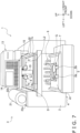
- FIG. 7 is an external view of the packaging apparatus 1 in step S2.
- the tray conveyance mechanism 5 (the pusher 5a and the pusher 5b) rise from under the weigh table 41 and abut against the front side surface of the tray T (step S2).
- FIG. 8 is an external view of the packaging apparatus 1 in step S3.
- the tray conveyance mechanism 5 conveys the tray T rearward (to the lift unit 6) (step S3).
- FIG. 9 is an external view of the packaging apparatus 1 in step S4.
- the tray T is lifted by the lift unit 6 to the packaging position L1, and the upper portion of the tray T becomes covered by the film F (step S4).
- FIG. 10 is a right side view showing the discharge pusher 8 and the tray T in step S4.
- the discharge pusher 8 is lifted up about the horizontal shaft 87 in accordance with the size of the tray T lifted by the lift unit 6. For example, if the tray T is a large size, the longest first pusher member 81a and second pusher member 82a and the next longest first pusher member 81b and second pusher member 82b are lifted up by and ride on the tray T.
- the folding unit 7 folds, under the bottom of the tray T, the peripheral edge portions of the film F that has covered the tray T (step S5).
- FIG. 11 is an external view of the packaging apparatus 1 in a state in which the rear folding member 7a has moved close to the front folding member 7d in step S5.
- FIG. 12 is a right side view in which the longest first pusher member 81a and second pusher member 82a are riding on the tray T and the next longest first pusher member 81b and second pusher member 82b discharge the tray T without riding on it in step S5.
- the tray T is moved forward (in the first direction D) by the rear folding member 7a.
- the first member 812b and the first projection 813b that did not ride on the tray T contact the rear side surface of the tray T and discharge the tray T. Because of this, the discharge pusher 8 is configured so that even when the rear folding member 7a moves to the front folding member 7d and, for example a large-size tray T is pushed out to the discharge position L2, the tray T does not fall from the discharge position L2.
- FIG. 13 is a right side view showing the conventional discharge pusher P1 and a tray Td1 in step S5.
- the discharge pusher P1 has the space C. For that reason, there are cases where the tray Td1 tilts or the discharge pusher P1 moves up and down, and the tray Td1 gets caught in at least either of the space C and the groove P4. In contrast, as shown in FIG. 12 , the space C is not formed in the discharge pusher 8, and a situation where the tray T gets caught in at least either of the space C and the groove P4 is inhibited.
- FIG. 14 is an external view of the packaging apparatus 1 in step S6.
- the drive unit 9 is driven and causes the discharge pusher 8 to move in the first direction D and abut against the rear side surface of the tray T (step S6).
- FIG. 15 is a right side view in which, when the size of the tray T is small, the first member 812a and the first projection 813a of the first pusher member 81a are abutting against the rear side surface of the tray T.
- FIG. 16 is a right side view showing the conventional discharge pusher P1 and a tray Td2 in a case that the height of tray Td2 is low.
- the discharge pusher P1 has the space C.
- the member P2 and the projection P3 abut against the tray Td2 a situation can occur where the tray Td2 gets caught in at least either of the space C and the groove P4.
- the space C is not formed in the discharge pusher 8, and a situation where the tray T gets caught in at least either of the space C and the groove P4 is inhibited.
- FIG. 17 is an external view of the packaging apparatus 1 in step S7.
- the drive unit 9 is driven and causes the discharger pusher 8 to move further in the first direction D.
- the discharge pusher 8 advances in the first direction D in a state in which it is abutting against the rear side surface of the tray T and discharges the tray T to the discharge position L2 (step S7).
- step S7 the lift unit 6 is lowered and goes back to its state before it was raised. Furthermore, during or before step S7, the label issuing unit 13 receives information from the control unit and issues the label La on which the product information such as the weight, price, and name of the article G is printed. The user takes the issued label La from the label issuing unit 13 and can stick it on the film F of the discharged tray T.
- the discharge pusher 8 is returned to its position before it discharged the tray T (e.g., the position of the discharge pusher 8 in FIG. 6 ). If the tray Td1 or the tray Td2 is caught in the conventional discharge pusher P1, the discharge pusher P1 that is returned may also pull back the tray Td1 or the tray Td2 from the discharge position L2 to the packaging position L1. However, in the discharge pusher 8 of the present embodiment, such catching does not occur.
- the packaging apparatus 1 includes the film conveyance unit 3, the lift unit 6, the folding unit 7, and the discharge pusher 8.
- the film conveyance unit 3 conveys, in an extended state, the film F unwound from the film roll 21 to the packaging position L1.
- the lift unit 6 lifts the tray T containing the article G toward the film F disposed in the packaging position L1.
- the folding unit 7 folds, under the bottom of the tray T, a peripheral edge portion of the film F that has covered the tray T.
- the discharge pusher 8 pushes one side surface of the tray T packaged by the film F to discharge in the first direction D the tray T covered by the film F.
- the discharge pusher 8 includes the first pusher member 81.
- the first pusher member 81 has the first arm 811, the first member 812, and the first projection 813.
- the first arm 811 extends in the first direction D.
- the first member 812 extends in a direction intersecting the first direction D at the distal end portion of the first arm 811 and abuts against the side surface of the tray T.
- the first projection 813 extends in the first direction D beyond the first member 812 from the distal end portion of the first arm 811 and abuts against the lower portion of the side surface of the tray T.
- the lower end of the first member 812 is positioned lower than the upper end of the first projection 813.
- the packaging apparatus 1 can inhibit the pulling back of trays by the discharge pusher 8. (6-2)
- the first pusher member 81 is swingable up and down about the horizontal shaft 87 that is located in a position away from the packaging position L1 and extends in a direction orthogonal to the first direction D.
- the discharge pusher 8 includes a plurality of the first pusher members 81 in which the lengths of the first arms 811 from the horizontal shaft 87 to the distal end portions are different. Consequently, when the tray T is a large size, the longest first pusher member 81a and the next longest first pusher member 81b of the first pusher members 81 ride on the tray T, and the shortest first pusher member 81c abuts the side surface of the tray T and discharges the tray T. Furthermore, when the tray T is an intermediate size, the longest first pusher member 81a rides on the tray T, and the next longest first pusher member 81b abuts the side surface of the tray T and discharges the tray T. Moreover, when the tray T is a small size, the longest first pusher member 81a abuts the side surface of the tray T and discharges the tray T.
- each tray T can be stopped in a fixed position in the discharge position L2 and prevented from falling forward.
- the discharge pusher 8 further includes the second pusher member 82.
- the second pusher member 82 has the second arm 821, the second member 822, and the second projection 823.
- the second arm 821 extends in the first direction D.
- the second member 822 extends in a direction intersecting the first direction D at the distal end portion of the second arm 821 and abuts against the side surface of the tray T.
- the second projection 823 extends in the first direction D beyond the second member 822 from the distal end portion of the second arm 821 and abuts against the lower portion of the side surface of the tray T.
- the lower end of the second member 822 is positioned lower than the upper end of the second projection 823.
- the first pusher member 81 and the second pusher member 82 are disposed planarly symmetrical to each other relative to a vertical plane extending in the first direction D.
- the packaging apparatus 1 can discharge the tray T in the first direction D in correspondence to the state of the tray T of various states. (6-5)
- the plural first pusher members 81 are disposed such that, the longer the length of the first arm 811 from the horizontal shaft 87 to the distal end portion is, the more inward they are.
- the packaging apparatus 1 can be made smaller. (6-6)
- the packaging apparatus 1 further includes the restraining member 10.
- the restraining member 10 restrains, from above, the tray T covered by the film F when the discharge pusher 8 moves the tray T in the first direction D. Because of this, the tray T can be inhibited from turnover when it is discharged from the packaging position L1.
- Patent Document 1 JP-ANo. 2011-20700
Landscapes
- Engineering & Computer Science (AREA)
- Mechanical Engineering (AREA)
- Basic Packing Technique (AREA)
Abstract
Providing a packaging apparatus that can inhibit the pulling back of trays by a discharge pusher. A packaging apparatus (1) includes a film conveyance unit (3), a lift unit (6), a folding unit (7), and a discharge pusher (8). The film conveyance unit (3) conveys a film (T) to a packaging position (L1). The lift unit (6) lifts a tray (T) toward the packaging position (L1). The folding unit (7) folds a peripheral edge portion of the film (F) that has covered the tray (T). The discharge pusher (8) pushes a side surface of the tray (T) to discharge the tray (T) in a first direction (D). The discharge pusher (8) includes a first pusher member (81). The first pusher member (81) has a first arm (811), a first member (812), and a first projection (813). The first member (812) extends in a direction intersecting the first direction (D) and abuts against a side surface of the tray (T). The first projection (813) extends in the first direction (D) beyond the first member (812) and abuts against a lower portion of the side surface of the tray (T). A lower end of the first member (812) is positioned lower than an upper end of the first projection (813).
Description
- The present invention relates to a packaging apparatus.
- Patent Document 1 (
JP-A No. 2011-20700 - In a conventional packaging machine, when the discharge pusher discharges the trays from the packaging position, sometimes the distal end of the discharge pusher gets caught on the trays such that, when the discharge pusher goes back, the trays are pulled back to the packaging position and are not completely discharged from the packaging machine.
- The packaging machine disclosed in
Patent Document 1 also does not consider the problem of relatively light trays being pulled back by the discharge pusher. - It is an object of the present invention to provide a packaging apparatus that can inhibit the pulling back of trays by the discharge pusher.
- A packaging apparatus according to a first aspect includes a film conveyance unit, a lift unit, a folding unit, and a discharge pusher. The film conveyance unit is configured to convey, in an extended state, a film unwound from a film roll to a packaging position. The lift unit is configured to lift a tray containing an article toward the film disposed in the packaging position. The folding unit is configured to fold, under the bottom of the tray, a peripheral edge portion of the film that has covered the tray. The discharge pusher is configured to push one side surface of the tray packaged by the film to discharge in a first direction the tray covered by the film. The discharge pusher includes a first pusher member. The first pusher member has a first arm, a first member, and a first projection. The first arm extends in the first direction. The first member extends in a direction intersecting the first direction at a distal end portion of the first arm and is configured to abut against the side surface of the tray. The first projection extends in the first direction beyond the first member from the distal end portion of the first arm and is configured to abut against a lower portion of the side surface of the tray. A lower end of the first member is positioned lower than an upper end of the first projection.
- This packaging apparatus can inhibit the pulling back of trays by the discharge pusher.
- A packaging apparatus according to a second aspect is the packaging apparatus of the first aspect, wherein the first pusher member is configured to swing up and down about a horizontal shaft that is located in a position away from the packaging position and extends in a direction orthogonal to the first direction.
- A packaging apparatus according to a third aspect is the packaging apparatus of the second aspect, wherein the discharge pusher includes a plurality of the first pusher members in which the lengths of the first arms from the horizontal shaft to the distal end portions are different.
- A packaging apparatus according to a fourth aspect is the packaging apparatus of any of the first to third aspect, wherein the discharge pusher further includes a second pusher member. The second pusher member has a second arm, a second member, and a second projection. The second arm extends in the first direction. The second member extends in a direction intersecting the first direction at a distal end portion of the second arm and is configured to abut against the side surface of the tray. The second projection extends in the first direction beyond the second member from the distal end portion of the second arm and is configured to abut against a lower portion of the side surface of the tray. A lower end of the second member is positioned lower than an upper end of the second projection. The first pusher member and the second pusher member are disposed planarly symmetrical to each other relative to a vertical plane extending in the first direction.
- A packaging apparatus according to a fifth aspect is the packaging apparatus of the third aspect, wherein the plural first pusher members are disposed such that, the longer the length of the first arm from the horizontal shaft to the distal end portion is, the more inward they are.
- A packaging apparatus according to the sixth aspect is the packaging apparatus of any of the first aspect to the fifth aspect, further including a restraining member. The restraining member is configured to restrains, from above, the tray covered by the film in a case where the discharge pusher moves the tray in the first direction.
- The packaging apparatus pertaining to the present invention can inhibit the pulling back of trays by the discharge pusher.
-
-
FIG. 1 is an external view showing a tray T containing an article G; -
FIG. 2 is an external view of apackaging apparatus 1; -
FIG. 3 is a perspective view showing a conventional discharge pusher P1; -
FIG. 4 is a perspective view showing adischarge pusher 8; -
FIG. 5 is a flowchart showing the operation of thepackaging apparatus 1; -
FIG. 6 is an external view of thepackaging apparatus 1; -
FIG. 7 is an external view of thepackaging apparatus 1; -
FIG. 8 is an external view of thepackaging apparatus 1; -
FIG. 9 is an external view of thepackaging apparatus 1; -
FIG. 10 is a right side view showing thedischarge pusher 8 and the tray T; -
FIG. 11 is an external view of thepackaging apparatus 1; -
FIG. 12 is a right side view showing thedischarge pusher 8 and the tray T; -
FIG. 13 is a right side view showing the conventional discharge pusher P1 and a tray Td1; -
FIG. 14 is an external view of thepackaging apparatus 1; -
FIG. 15 is a right side view showing thedischarge pusher 8 and the tray T; -
FIG. 16 is a right side view showing the conventional discharge pusher P1 and a tray Td2; and -
FIG. 17 is an external view of thepackaging apparatus 1. - The packaging apparatus of the present application uses a film F to package a tray T containing an article G (hereinafter sometimes abbreviated as "tray T") and discharges the tray T with a discharge pusher P1.
-
FIG. 1 is an external view showing the tray T containing the article G, which is an item to be packaged by the packaging apparatus. The tray T has a shape with an opening in the upper portion thereof, and has a shape where the opening in the upper portion is wider than the bottom of the tray T. Examples of the article G include foods, but the article G is not limited to this. - The overall configuration of a
packaging apparatus 1 pertaining to the present invention will now be described.FIG. 2 is an external view of thepackaging apparatus 1. Thepackaging apparatus 1 weighs the tray T containing the article G, uses the film F to package it, discharges the tray T, and issues a label La on which product information such as the price of the article G is printed. - The
packaging apparatus 1 mainly includes afilm support unit 2, afilm conveyance unit 3, aweighing unit 4, atray conveyance mechanism 5, alift unit 6, afolding unit 7, adischarge pusher 8, adrive unit 9, arestraining member 10, alabel issuing unit 13, adisplay unit 14, anoperation unit 15, and a control unit (not shown in the drawings). - The operation of the
packaging apparatus 1 will be briefly described. In thepackaging apparatus 1, the tray T containing the article G is placed on the weighingunit 4. The weighingunit 4 weighs the tray T containing the article G. The weighing result obtained by the weighingunit 4 is sent to the control unit. The control unit causes thedisplay unit 14 to display the weighing result. Thelift unit 6 lifts to a packaging position L1 the tray T conveyed thereto from the weighingunit 4. In the packaging position L1, the film F is held in a stretched state. Thelift unit 6 lifts the tray T to push up the tray T against the film F stretched in the packaging position L1 and cover the tray T with the film F. Thereafter, thefolding unit 7 folds a peripheral edge portion of the film F under the tray T covered by the film F to thereby package the tray T. Thedischarge pusher 8 discharges the packaged tray T to a discharge position L2. Thelabel issuing unit 13 issues the label La on which the product information is printed. On the label La are printed the weight of the article G contained in the tray T and the price of the article pertaining to that tray T. The control unit calculates the weight and the price based on the weighing result obtained by the weighingunit 4. -
FIG. 3 is a perspective view showing the conventional discharge pusher P1. The discharge pusher P1 mainly has a member P2, a projection P3, and a groove P4. The member P2 abuts against a side surface of the tray T. The projection P3 abuts against a lower portion of the side surface of the tray T. The groove P4 is a "relief' portion formed when bending the member P2, and is a recessed portion formed at the intersection of the projection P3 and the member P2. The lower end of the member P2 is positioned higher than the upper end of the projection P3. Between the lower end of the member P2 and the upper end of the projection P3 is formed a space C. The space C is a space whose bottom lies in a plane that extends in the left and right direction and the front and rear direction and includes the upper end of the projection P3 and whose top lies in a plane that extends in the left and right direction and the front and rear direction and includes the lower end of the member P2. - In a state in which the member P2 and the projection P3 are abutting against the tray T, the discharge pusher P1 discharges the tray T. If a shallow tray T tilts forward or backward during the discharge, the edge of the tray T can get stuck in at least either of the space C and the groove P4. For that reason, if the distal end of the discharge pusher P1 gets caught on the tray T, a problem may occur where, in a case where the tray T is light, it gets pulled back when the discharge pusher P1 goes back and the tray T is not completely discharged.
- The
film support unit 2 supports afilm roll 21 in which the film F is wound in a roll. Thefilm support unit 2 has a pair of support rollers 22 (asupport roller 22a and asupport roller 22b) that support the side surface of the lower portion of thefilm roll 21 from the left and right sides. Furthermore, thefilm support unit 2 has one or a plurality of guide rollers (not shown in the drawings) that guide to thefilm conveyance unit 3 the film F unwound from thefilm roll 21. Inside thefilm support unit 2 is provided a holding unit (not shown in the drawings) that tensely holds, in a state in which it applies tension to, end portions of the film F. - The
film conveyance unit 3 conveys, in an extended state, the film F unwound from thefilm roll 21 to the packaging position L1. For that purpose, thefilm conveyance unit 3 has upper andlower conveyance rollers 31, afilm feed unit 32, and a film cutting unit (not shown in the drawings). - The upper and
lower conveyance rollers 31 are driven to rotate and convey to thefilm feed unit 32 the film F unwound from thefilm support unit 2. Thefilm feed unit 32 grips with upper and lower belts and conveys to the packaging position L1 both front and rear direction end portions of the film F. When the film F is conveyed to the packaging position L1, the film cutting unit cuts the film F and cuts it away from thefilm roll 21. - The weighing
unit 4 measures the weight of the article G, which has been placed on a weigh table 41, and sends to the control unit weight information including the tare of the tray T containing the article G. - The
tray conveyance mechanism 5 has a pair of conveyance mechanisms (apusher 5a and apusher 5b) that convey the tray T containing the article G from the weigh table 41 to thelift unit 6. - When the weighing
unit 4 measures the weight, thetray conveyance mechanism 5 is retracted under the weigh table 41, and when the weighing by the weighingunit 4 ends, thetray conveyance mechanism 5 rises from under the weigh table 41 and advances rearward in a state in which it abuts against the front side surface of the tray T to convey the tray T to thelift unit 6. - The
lift unit 6 lifts the tray T containing the article G toward the film F disposed in the packaging position L1. Thelift unit 6 is configured by a plurality oflift members 61. - The
folding unit 7 folds, under the bottom of the tray T, a peripheral edge portion of the film F that has covered the tray T. Thefolding unit 7 includes arear folding member 7a, aleft folding member 7b, aright folding member 7c, and afront folding member 7d. - The
rear folding member 7a moves forward and folds the film F on the rear side of the tray T under the bottom on the rear side of the tray T. Theleft folding member 7b moves rightward and folds the film F on the left side of the tray T under the bottom on the left side of the tray T. Theright folding member 7c moves leftward and folds the film F on the right side of the tray T under the bottom of the right side of the tray T. Thefront folding member 7d folds, under the bottom on the front side of the tray T, the film F on the front side of the tray T moved forward by therear folding member 7a. - The
discharge pusher 8 pushes forward, from the rear side, one side surface of the tray T packaged by the film F to discharge in a first direction D (seeFIG. 4 ) the tray T covered by the film F. In the present embodiment, the "one side surface" is the rear side surface, and the first direction D is the forward direction. The tray T is discharged from the packaging position L1 to the discharge position L2 by thedischarge pusher 8. -
FIG. 4 is a perspective view showing thedischarge pusher 8. Thedischarge pusher 8 includes three first pusher members 81 (81a, 81b, 81c) and three second pusher members 82 (82a, 82b, 82c). It will be noted that thedischarge pusher 8 may include one, two, or four or morefirst pusher members 81 and may include one, two, or four or moresecond pusher members 82. - The
first pusher member 81a has afirst arm 811a, afirst member 812a, afirst projection 813a, and afirst groove 814a. Thefirst pusher member 81b has afirst arm 811b, afirst member 812b, afirst projection 813b (not shown in the drawings), and a first groove 814b (not shown in the drawings). Thefirst pusher member 81c has afirst arm 811c, afirst member 812c, a first projection 813c (not shown in the drawings), and a first groove 814c (not shown in the drawings). Thefirst pusher members first arms - The
first pusher members 81 are swingable up and down about ahorizontal shaft 87 that is located in a position away from the discharge position L1 and extends in a direction orthogonal to the first direction D. - The
first arms - The length of the
first arm 811a from thehorizontal shaft 87 to the distal end portion of thefirst arm 811a is longer than the length of thefirst arm 811b from thehorizontal shaft 87 to the distal end portion of thefirst arm 811b. The length of thefirst arm 811b from thehorizontal shaft 87 to the distal end portion of thefirst arm 811b is longer than the length of thefirst arm 811c from thehorizontal shaft 87 to the distal end portion of thefirst arm 811c. - The
first arm 811a is disposed on the inner side, thefirst arm 811c is disposed on the outer side, and thefirst arm 811b is disposed between thefirst arm 811a and thefirst arm 811b. In other words, thefirst pusher members 81 are disposed such that, the longer the length of the first arm 811 from thehorizontal shaft 87 to the distal end portion is, the more inward they are. - The
first members first member 812a extends in a direction intersecting the first direction D at the distal end portion of thefirst arm 811a and abuts against the side surface of the tray T when thedischarge pusher 8 discharges the tray T. Examples of the "direction intersecting the first direction D" include "a direction (rightward direction) orthogonal to the first direction D." It will be noted that the "direction intersecting the first direction D" need not be a direction orthogonal to the first direction D. Thefirst member 812b extends in a direction intersecting the first direction D at the distal end portion of thefirst arm 811b and abuts against the side surface of the tray T when thedischarge pusher 8 discharges the tray T. Thefirst member 812c extends in a direction intersecting the first direction D at the distal end portion of thefirst arm 811c and abuts against the side surface of the tray T when thedischarge pusher 8 discharges the tray T. - The
first projections first projection 813a extends in the first direction D beyond thefirst member 812a from the distal end portion of thefirst arm 811a and abuts against the lower portion of the side surface of the tray T when thedischarge pusher 8 discharges the tray T. Thefirst projection 813b extends in the first direction D beyond thefirst member 812b from the distal end portion of thefirst arm 811b and abuts against the lower portion of the side surface of the tray T when thedischarge pusher 8 discharges the tray T. The first projection 813c extends in the first direction D beyond thefirst member 812c from the distal end portion of thefirst arm 811c and abuts against the lower portion of the side surface of the tray T when thedischarge pusher 8 discharges the tray T. - The lower end of the
first member 812a is positioned lower than the upper end of thefirst projection 813a. The lower end of thefirst member 812b is positioned lower than the upper end of thefirst projection 813b. The lower end of thefirst member 812c is positioned lower than the upper end of the first projection 813c. For that reason, in thefirst pusher members FIG. 3 ) in the conventional discharge pusher P1 is not formed. - The
first groove 814a is a "relief' formed at the intersection between thefirst member 812a and thefirst projection 813a and is a recessed part in the distal end of thefirst arm 811a. Likewise, the first groove 814b is a "relief' formed at the intersection between thefirst member 812b and thefirst projection 813b, and the first groove 814c is a "relief' formed at the intersection between thefirst member 812c and the first projection 813c. - The
discharge pusher 8 includes thesecond pusher members second pusher member 82a has asecond arm 821a, asecond member 822a, asecond projection 823a, and asecond groove 824a. Thesecond pusher member 82b has asecond arm 821b, asecond member 822b, a second projection 823b (not shown in the drawings), and a second groove 824b (not shown in the drawings). Thesecond pusher member 82c has asecond arm 821c, asecond member 822c, a second projection 823c (not shown in the drawings), and a second groove 824c (not shown in the drawings). Thefirst pushere members first arms - The
second pusher member 82a, thesecond pusher member 82b, and thesecond pusher member 82c are swingable up and down about thehorizontal shaft 87 that is located in a position away from the discharge position L1 and extends in a direction orthogonal to the first direction D. Thesecond pusher member 82a, thesecond pusher member 82b, and thesecond pusher member 82c are secured, by for example bolts (not shown in the drawings) provided in thehorizontal shaft 87, such that they freely rotate. - The
second pusher members first pusher members - The
second arms - The length of the
second arm 821a from thehorizontal shaft 87 to the distal end portion of thesecond arm 821a is longer than the length of thesecond arm 821b from thehorizontal shaft 87 to the distal end portion of thesecond arm 821b. The length of thesecond arm 821b from thehorizontal shaft 87 to the distal end portion of thesecond arm 821b is longer than the length of thesecond arm 821c from thehorizontal shaft 87 to the distal end portion of thesecond arm 821c. - The
second arm 821a is disposed on the inner side, thesecond arm 821c is disposed on the outer side, and thesecond arm 821b is disposed between thesecond arm 821a and thesecond arm 821b. In other words, thesecond pusher members 82 are disposed such that, the longer the length of the second arm 821 from thehorizontal shaft 87 to the distal end portion is, the more inward they are. - The
second members second member 822a extends in a direction intersecting the first direction D at the distal end portion of thesecond arm 821a and abuts against the side surface of the tray T when thedischarge pusher 8 discharges the tray T. Thesecond member 822b extends in a direction intersecting the first direction D at the distal end portion of thesecond arm 821b and abuts against the side surface of the tray T when thedischarge pusher 8 discharges the tray T. Thesecond member 822c extends in a direction intersecting the first direction D at the distal end portion of thesecond arm 821c and abuts against the side surface of the tray T when thedischarge pusher 8 discharges the tray T. - The
second projections 823a, 823b, 823c are projecting members. Thesecond projection 823a extends in the first direction D beyond thesecond member 822a from the distal end portion of thesecond arm 821a and abuts against the lower portion of the side surface of the tray T when thedischarge pusher 8 discharges the tray T. The second projection 823b (not shown in the drawings) extends in the first direction D beyond thesecond member 822b from the distal end portion of thesecond arm 821b and abuts against the lower portion of the side surface of the tray T when thedischarge pusher 8 discharges the tray T. The second projection 823c (not shown in the drawings) extends in the first direction D beyond thesecond member 822c from the distal end portion of thesecond arm 821c and abuts against the lower portion of the side surface of the tray T when thedischarge pusher 8 discharges the tray T. - The lower end of the
second member 822a is positioned lower than the upper end of thesecond projection 823a. The lower end of thesecond member 822b is positioned lower than the upper end of the second projection 823b. The lower end of thesecond member 822c is positioned lower than the upper end of the second projection 823c. For that reason, in thesecond pusher members FIG. 3 ) in the conventional discharge pusher P1 is not formed. - The
second groove 824a is a "relief' formed at the intersection between thesecond member 822a and thesecond projection 823a and is a recessed part in the distal end of thesecond arm 821a. The second groove 824b is a "relief' formed at the intersection between thesecond member 822b and the second projection 823b and is a recessed part in the distal end of thesecond arm 822b. The second groove 824c is a "relief' formed at the intersection between thesecond member 822c and the second projection 823c and is a recessed part in the distal end of thesecond arm 821c. - The
drive unit 9 is a single device that collectively causes the threefirst pusher members 81 and the threesecond pusher members 82 to move in a direction along the first direction D. Thedrive unit 9 is, for example, a motor provided inside thepackaging apparatus 1. - The restraining
member 10 is a long and narrow plate-like member and is disposed in the front and rear direction between thefirst pusher members second pusher members member 10 is attached to the apparatus frame via a parallel link mechanism so as to be movable in the up and down direction and immovable in the front and rear direction. The restrainingmember 10 inhibits the tray T from turnover by restraining, from above with its own weight, the tray T covered by the film F when thedischarge pusher 8 moves the tray T in the first direction D. - The
label issuing unit 13 issues the label La on which the product information such as the weight, price, and name of the article G is printed. Thedisplay unit 14 is a display device that displays the product information such as the weight, price, and name of the article G. It will be noted that thedisplay unit 14 may be a touch panel operable by the user. Theoperation unit 15 is configured by a plurality of buttons which, as a result of being depressed by the user, allow the user to operate content input to thepackaging apparatus 1. The control unit controls each of the components of thepackaging apparatus 1. - The operation of the packaging apparatus 1 (with emphasis given particularly to operations associated with the discharge of the tray T by the discharge pusher 8) will now be described while comparing the
discharge pusher 8 with the conventional discharge pusher P1.FIG. 5 is a flowchart showing the operation of thepackaging apparatus 1. -
FIG. 6 is an external view of thepackaging apparatus 1 in step S1. The user operates theoperation unit 15 to call up the product information relating to the target product (hereinafter, "the article G") and thereafter places the tray T containing the article G on the weigh table 41 (step S1). Thereafter, the weighingunit 4 measures the total weight of the tray T containing the article G that has been placed on the weigh table 41. The weighingunit 4 sends the total weight of the tray T it has acquired to the control unit. The control unit calculates the net weight of the article G based on the tare weight of the tray T that was called up and the total weight of the tray T. Thedisplay unit 14 displays the weight and price of the article G calculated by the control unit. -
FIG. 7 is an external view of thepackaging apparatus 1 in step S2. The tray conveyance mechanism 5 (thepusher 5a and thepusher 5b) rise from under the weigh table 41 and abut against the front side surface of the tray T (step S2). -
FIG. 8 is an external view of thepackaging apparatus 1 in step S3. Thetray conveyance mechanism 5 conveys the tray T rearward (to the lift unit 6) (step S3). -
FIG. 9 is an external view of thepackaging apparatus 1 in step S4. The tray T is lifted by thelift unit 6 to the packaging position L1, and the upper portion of the tray T becomes covered by the film F (step S4).FIG. 10 is a right side view showing thedischarge pusher 8 and the tray T in step S4. Thedischarge pusher 8 is lifted up about thehorizontal shaft 87 in accordance with the size of the tray T lifted by thelift unit 6. For example, if the tray T is a large size, the longestfirst pusher member 81a andsecond pusher member 82a and the next longestfirst pusher member 81b andsecond pusher member 82b are lifted up by and ride on the tray T. Furthermore, if the tray T is an intermediate size, thefirst pusher member 81a and thesecond pusher member 82a are lifted up by and ride on the tray T. Furthermore, if the tray T is a small size, thefirst pusher member 81a and thesecond pusher member 82a discharge the tray T without riding on it. Next, thefolding unit 7 folds, under the bottom of the tray T, the peripheral edge portions of the film F that has covered the tray T (step S5). -
FIG. 11 is an external view of thepackaging apparatus 1 in a state in which therear folding member 7a has moved close to thefront folding member 7d in step S5.FIG. 12 is a right side view in which the longestfirst pusher member 81a andsecond pusher member 82a are riding on the tray T and the next longestfirst pusher member 81b andsecond pusher member 82b discharge the tray T without riding on it in step S5. In step S5, the tray T is moved forward (in the first direction D) by therear folding member 7a. For that reason, thefirst member 812b and thefirst projection 813b that did not ride on the tray T contact the rear side surface of the tray T and discharge the tray T. Because of this, thedischarge pusher 8 is configured so that even when therear folding member 7a moves to thefront folding member 7d and, for example a large-size tray T is pushed out to the discharge position L2, the tray T does not fall from the discharge position L2. -
FIG. 13 is a right side view showing the conventional discharge pusher P1 and a tray Td1 in step S5. The discharge pusher P1 has the space C. For that reason, there are cases where the tray Td1 tilts or the discharge pusher P1 moves up and down, and the tray Td1 gets caught in at least either of the space C and the groove P4. In contrast, as shown inFIG. 12 , the space C is not formed in thedischarge pusher 8, and a situation where the tray T gets caught in at least either of the space C and the groove P4 is inhibited. -
FIG. 14 is an external view of thepackaging apparatus 1 in step S6. Thedrive unit 9 is driven and causes thedischarge pusher 8 to move in the first direction D and abut against the rear side surface of the tray T (step S6).FIG. 15 is a right side view in which, when the size of the tray T is small, thefirst member 812a and thefirst projection 813a of thefirst pusher member 81a are abutting against the rear side surface of the tray T. -
FIG. 16 is a right side view showing the conventional discharge pusher P1 and a tray Td2 in a case that the height of tray Td2 is low. In this case, the discharge pusher P1 has the space C. For that reason, when the member P2 and the projection P3 abut against the tray Td2, a situation can occur where the tray Td2 gets caught in at least either of the space C and the groove P4. - In contrast, as shown in
FIG. 15 , the space C is not formed in thedischarge pusher 8, and a situation where the tray T gets caught in at least either of the space C and the groove P4 is inhibited. -
FIG. 17 is an external view of thepackaging apparatus 1 in step S7. Thedrive unit 9 is driven and causes thedischarger pusher 8 to move further in the first direction D. Thedischarge pusher 8 advances in the first direction D in a state in which it is abutting against the rear side surface of the tray T and discharges the tray T to the discharge position L2 (step S7). - During or after step S7, the
lift unit 6 is lowered and goes back to its state before it was raised. Furthermore, during or before step S7, thelabel issuing unit 13 receives information from the control unit and issues the label La on which the product information such as the weight, price, and name of the article G is printed. The user takes the issued label La from thelabel issuing unit 13 and can stick it on the film F of the discharged tray T. - After step S7, the
discharge pusher 8 is returned to its position before it discharged the tray T (e.g., the position of thedischarge pusher 8 inFIG. 6 ). If the tray Td1 or the tray Td2 is caught in the conventional discharge pusher P1, the discharge pusher P1 that is returned may also pull back the tray Td1 or the tray Td2 from the discharge position L2 to the packaging position L1. However, in thedischarge pusher 8 of the present embodiment, such catching does not occur. - (6-1)
Thepackaging apparatus 1 includes thefilm conveyance unit 3, thelift unit 6, thefolding unit 7, and thedischarge pusher 8. Thefilm conveyance unit 3 conveys, in an extended state, the film F unwound from thefilm roll 21 to the packaging position L1. Thelift unit 6 lifts the tray T containing the article G toward the film F disposed in the packaging position L1. Thefolding unit 7 folds, under the bottom of the tray T, a peripheral edge portion of the film F that has covered the tray T. Thedischarge pusher 8 pushes one side surface of the tray T packaged by the film F to discharge in the first direction D the tray T covered by the film F. Thedischarge pusher 8 includes thefirst pusher member 81. Thefirst pusher member 81 has the first arm 811, the first member 812, and the first projection 813. The first arm 811 extends in the first direction D. The first member 812 extends in a direction intersecting the first direction D at the distal end portion of the first arm 811 and abuts against the side surface of the tray T. The first projection 813 extends in the first direction D beyond the first member 812 from the distal end portion of the first arm 811 and abuts against the lower portion of the side surface of the tray T. The lower end of the first member 812 is positioned lower than the upper end of the first projection 813. - The
packaging apparatus 1 can inhibit the pulling back of trays by thedischarge pusher 8.
(6-2) - In the
packaging apparatus 1, thefirst pusher member 81 is swingable up and down about thehorizontal shaft 87 that is located in a position away from the packaging position L1 and extends in a direction orthogonal to the first direction D. - In the process of the packaging of the tray T, the tray T is pushed upward, beyond the position where the film F is stretched, by the rising of the
lift unit 6. At that time, thefirst pusher member 81 of the threefirst pusher members 81 that did not ride on the tray T discharges the tray T.
(6-3) - In the
packaging apparatus 1, thedischarge pusher 8 includes a plurality of thefirst pusher members 81 in which the lengths of the first arms 811 from thehorizontal shaft 87 to the distal end portions are different. Consequently, when the tray T is a large size, the longestfirst pusher member 81a and the next longestfirst pusher member 81b of thefirst pusher members 81 ride on the tray T, and the shortestfirst pusher member 81c abuts the side surface of the tray T and discharges the tray T. Furthermore, when the tray T is an intermediate size, the longestfirst pusher member 81a rides on the tray T, and the next longestfirst pusher member 81b abuts the side surface of the tray T and discharges the tray T. Moreover, when the tray T is a small size, the longestfirst pusher member 81a abuts the side surface of the tray T and discharges the tray T. - Because of this, even when the tray sizes are different, each tray T can be stopped in a fixed position in the discharge position L2 and prevented from falling forward.
(6-4) - In the
packaging apparatus 1, thedischarge pusher 8 further includes thesecond pusher member 82. Thesecond pusher member 82 has the second arm 821, the second member 822, and the second projection 823. The second arm 821 extends in the first direction D. The second member 822 extends in a direction intersecting the first direction D at the distal end portion of the second arm 821 and abuts against the side surface of the tray T. The second projection 823 extends in the first direction D beyond the second member 822 from the distal end portion of the second arm 821 and abuts against the lower portion of the side surface of the tray T. The lower end of the second member 822 is positioned lower than the upper end of the second projection 823. Thefirst pusher member 81 and thesecond pusher member 82 are disposed planarly symmetrical to each other relative to a vertical plane extending in the first direction D. - Because of this, the
first pusher member 81 and thesecond pusher member 82 can abut against the tray T in two places. For that reason, even when the center of gravity of the tray T varies, the tray T is discharged in the first direction D if the center of gravity of the tray T is inside the two places at which thefirst pusher member 81 and thesecond pusher member 82 abut against the tray T (inside of sides where there are extension lines extending from the first direction D). Consequently, thepackaging apparatus 1 can discharge the tray T in the first direction D in correspondence to the state of the tray T of various states.
(6-5) - In the
packaging apparatus 1, the pluralfirst pusher members 81 are disposed such that, the longer the length of the first arm 811 from thehorizontal shaft 87 to the distal end portion is, the more inward they are. - Because of this, the
packaging apparatus 1 can be made smaller.
(6-6) - The
packaging apparatus 1 further includes the restrainingmember 10. The restrainingmember 10 restrains, from above, the tray T covered by the film F when thedischarge pusher 8 moves the tray T in the first direction D. Because of this, the tray T can be inhibited from turnover when it is discharged from the packaging position L1. -
- 1
- Packaging Apparatus
- 3
- Film Conveyance Unit
- 6
- Lift Unit
- 7
- Folding Unit
- 8
- Discharge Pusher
- 9
- Drive Unit
- 10
- Restraining Member
- 81
- First Pusher Member
- 82
- Second Pusher Member
- 87
- Horizontal Shaft
- 811
- First Arm
- 812
- First Member
- 813
- First Projection
- 821
- Second Arm
- 822
- Second Member
- 823
- Second Projection
- 21
- Film Roll
- D
- First Direction
- F
- Film
- G
- Article
- T
- Tray
- L1
- Packaging Position
- Patent Document 1: JP-ANo. 2011-20700
Claims (6)
- A packaging apparatus (1) comprising:a film conveyance unit (3) configured to convey, in an extended state, a film (F) unwound from a film roll (21) to a packaging position (L1);a lift unit (6) configured to lift a tray (T) containing an article (G) toward the film disposed in the packaging position;a folding unit (7) configured to fold, under the bottom of the tray, a peripheral edge portion of the film that has covered the tray; anda discharge pusher (8) configured to push a side surface of the tray packaged by the film to discharge in a first direction (D) the tray covered by the film;whereinthe discharge pusher includes:a first pusher member (81) having a first arm (811) that extends in the first direction,a first member (812) that extends in a direction intersecting the first direction at a distal end portion of the first arm and is configured to abut against the side surface of the tray, anda first projection (813) that extends in the first direction beyond the first member from the distal end portion of the first arm and is configured to abut against a lower portion of the side surface of the tray; anda lower end of the first member is positioned lower than an upper end of the first projection.
- The packaging apparatus according to claim 1, wherein the first pusher member is configured to swing up and down about a horizontal shaft (87) that is located in a position away from the packaging position and extends in a direction orthogonal to the first direction.
- The packaging apparatus according to claim 2, wherein the discharge pusher includes a plurality of the first pusher members in which lengths of the first arms from the horizontal shaft to the distal end portions are different.
- The packaging apparatus according to any one of claims 1 to 3, whereinthe discharge pusher further includes:a second pusher member (82) having a second arm (821) that extends in the first direction,a second member (822) that extends in a direction intersecting the first direction at a distal end portion of the second arm and is configured to abut against the side surface of the tray, anda second projection (823) that extends in the first direction beyond the second member from the distal end portion of the second arm and is configured to abut against a lower portion of the side surface of the tray;a lower end of the second member is positioned lower than an upper end of the second projection; andthe first pusher member and the second pusher member are disposed planarly symmetrical to each other relative to a vertical plane extending in the first direction.
- The packaging apparatus according to claim 3, wherein the plural first pusher members are disposed such that, the longer the length of the first arm from the horizontal shaft to the distal end portion is, the more inward they are.
- The packaging apparatus according to any one of claims 1 to 5, further comprising a restraining member (10) configured to restrain, from above, the tray covered by the film in a case where the discharge pusher moves the tray in the first direction.
Applications Claiming Priority (1)
| Application Number | Priority Date | Filing Date | Title |
|---|---|---|---|
| JP2023208760A JP2025093178A (en) | 2023-12-11 | 2023-12-11 | packaging equipment |
Publications (1)
| Publication Number | Publication Date |
|---|---|
| EP4574695A1 true EP4574695A1 (en) | 2025-06-25 |
Family
ID=93843331
Family Applications (1)
| Application Number | Title | Priority Date | Filing Date |
|---|---|---|---|
| EP24218241.8A Pending EP4574695A1 (en) | 2023-12-11 | 2024-12-09 | Packaging apparatus |
Country Status (3)
| Country | Link |
|---|---|
| EP (1) | EP4574695A1 (en) |
| JP (1) | JP2025093178A (en) |
| CN (1) | CN120135566A (en) |
Citations (3)
| Publication number | Priority date | Publication date | Assignee | Title |
|---|---|---|---|---|
| JPH0620887B2 (en) * | 1985-05-31 | 1994-03-23 | 株式会社寺岡精工 | Packing machine pusher mechanism |
| US20060272283A1 (en) * | 2005-06-01 | 2006-12-07 | Ishida Co., Ltd. | Packaging system |
| JP2011020700A (en) | 2009-07-15 | 2011-02-03 | Ishida Co Ltd | Packaging machine |
-
2023
- 2023-12-11 JP JP2023208760A patent/JP2025093178A/en active Pending
-
2024
- 2024-12-06 CN CN202411787263.1A patent/CN120135566A/en active Pending
- 2024-12-09 EP EP24218241.8A patent/EP4574695A1/en active Pending
Patent Citations (3)
| Publication number | Priority date | Publication date | Assignee | Title |
|---|---|---|---|---|
| JPH0620887B2 (en) * | 1985-05-31 | 1994-03-23 | 株式会社寺岡精工 | Packing machine pusher mechanism |
| US20060272283A1 (en) * | 2005-06-01 | 2006-12-07 | Ishida Co., Ltd. | Packaging system |
| JP2011020700A (en) | 2009-07-15 | 2011-02-03 | Ishida Co Ltd | Packaging machine |
Also Published As
| Publication number | Publication date |
|---|---|
| CN120135566A (en) | 2025-06-13 |
| JP2025093178A (en) | 2025-06-23 |
Similar Documents
| Publication | Publication Date | Title |
|---|---|---|
| JP6511064B2 (en) | Method and station for picking items according to the toy-to-person principle | |
| EP3798141B1 (en) | Article transfer device | |
| EP3251957B1 (en) | Packaging apparatus | |
| JP5641753B2 (en) | PTP cutting device | |
| CN113490628B (en) | Article holding device and support | |
| CN120135566A (en) | Packaging device | |
| JP2011207578A (en) | Commodity carrying device | |
| US20050232732A1 (en) | Intermediate store | |
| CN107924596A (en) | Method and apparatus for conveying and exporting roasting food | |
| JP5251058B2 (en) | Packaging device with label issuing device | |
| US20260131928A1 (en) | Weighing and conveying apparatus, and weighing, conveying, and packaging apparatus | |
| EP4566777A1 (en) | Packaging apparatus | |
| JP2017056989A (en) | Packaging equipment | |
| JP2024114510A (en) | Packaging Systems | |
| JP7519663B2 (en) | Packaging device, program, and control method using packaging device | |
| JP2026042514A (en) | Product processing equipment | |
| JP4600093B2 (en) | Stretch wrapping machine | |
| JP4639689B2 (en) | Packaging equipment | |
| AU2010242528A1 (en) | Improved packaging system | |
| KR0132046B1 (en) | Automatic vending machine | |
| JP4352318B2 (en) | Goods storage facility | |
| JP2025025410A (en) | Product Processing System | |
| JP2025082527A (en) | Boxing apparatus | |
| CN122035410A (en) | Metering and conveying device and metering, conveying and packaging device | |
| JP3094063U (en) | Product sorting device |
Legal Events
| Date | Code | Title | Description |
|---|---|---|---|
| PUAI | Public reference made under article 153(3) epc to a published international application that has entered the european phase |
Free format text: ORIGINAL CODE: 0009012 |
|
| STAA | Information on the status of an ep patent application or granted ep patent |
Free format text: STATUS: REQUEST FOR EXAMINATION WAS MADE |
|
| 17P | Request for examination filed |
Effective date: 20241209 |
|
| AK | Designated contracting states |
Kind code of ref document: A1 Designated state(s): AL AT BE BG CH CY CZ DE DK EE ES FI FR GB GR HR HU IE IS IT LI LT LU LV MC ME MK MT NL NO PL PT RO RS SE SI SK SM TR |