EP4574688A1 - A filling arrangement, a filling station and a method for filling a liquid food product comprising particles - Google Patents
A filling arrangement, a filling station and a method for filling a liquid food product comprising particles Download PDFInfo
- Publication number
- EP4574688A1 EP4574688A1 EP24214796.5A EP24214796A EP4574688A1 EP 4574688 A1 EP4574688 A1 EP 4574688A1 EP 24214796 A EP24214796 A EP 24214796A EP 4574688 A1 EP4574688 A1 EP 4574688A1
- Authority
- EP
- European Patent Office
- Prior art keywords
- filling
- arrangement
- package
- pipe
- opening
- Prior art date
- Legal status (The legal status is an assumption and is not a legal conclusion. Google has not performed a legal analysis and makes no representation as to the accuracy of the status listed.)
- Pending
Links
Images





Classifications
-
- B—PERFORMING OPERATIONS; TRANSPORTING
- B65—CONVEYING; PACKING; STORING; HANDLING THIN OR FILAMENTARY MATERIAL
- B65B—MACHINES, APPARATUS OR DEVICES FOR, OR METHODS OF, PACKAGING ARTICLES OR MATERIALS; UNPACKING
- B65B39/00—Nozzles, funnels or guides for introducing articles or materials into containers or wrappers
- B65B39/001—Nozzles, funnels or guides for introducing articles or materials into containers or wrappers with flow cut-off means, e.g. valves
- B65B39/004—Nozzles, funnels or guides for introducing articles or materials into containers or wrappers with flow cut-off means, e.g. valves moving linearly
-
- B—PERFORMING OPERATIONS; TRANSPORTING
- B65—CONVEYING; PACKING; STORING; HANDLING THIN OR FILAMENTARY MATERIAL
- B65B—MACHINES, APPARATUS OR DEVICES FOR, OR METHODS OF, PACKAGING ARTICLES OR MATERIALS; UNPACKING
- B65B3/00—Packaging plastic material, semiliquids, liquids or mixed solids and liquids, in individual containers or receptacles, e.g. bags, sacks, boxes, cartons, cans, or jars
-
- B—PERFORMING OPERATIONS; TRANSPORTING
- B65—CONVEYING; PACKING; STORING; HANDLING THIN OR FILAMENTARY MATERIAL
- B65B—MACHINES, APPARATUS OR DEVICES FOR, OR METHODS OF, PACKAGING ARTICLES OR MATERIALS; UNPACKING
- B65B3/00—Packaging plastic material, semiliquids, liquids or mixed solids and liquids, in individual containers or receptacles, e.g. bags, sacks, boxes, cartons, cans, or jars
- B65B3/04—Methods of, or means for, filling the material into the containers or receptacles
-
- B—PERFORMING OPERATIONS; TRANSPORTING
- B65—CONVEYING; PACKING; STORING; HANDLING THIN OR FILAMENTARY MATERIAL
- B65B—MACHINES, APPARATUS OR DEVICES FOR, OR METHODS OF, PACKAGING ARTICLES OR MATERIALS; UNPACKING
- B65B39/00—Nozzles, funnels or guides for introducing articles or materials into containers or wrappers
-
- B—PERFORMING OPERATIONS; TRANSPORTING
- B65—CONVEYING; PACKING; STORING; HANDLING THIN OR FILAMENTARY MATERIAL
- B65B—MACHINES, APPARATUS OR DEVICES FOR, OR METHODS OF, PACKAGING ARTICLES OR MATERIALS; UNPACKING
- B65B43/00—Forming, feeding, opening or setting-up containers or receptacles in association with packaging
- B65B43/42—Feeding or positioning bags, boxes, or cartons in the distended, opened, or set-up state; Feeding preformed rigid containers, e.g. tins, capsules, glass tubes, glasses, to the packaging position; Locating containers or receptacles at the filling position; Supporting containers or receptacles during the filling operation
- B65B43/46—Feeding or positioning bags, boxes, or cartons in the distended, opened, or set-up state; Feeding preformed rigid containers, e.g. tins, capsules, glass tubes, glasses, to the packaging position; Locating containers or receptacles at the filling position; Supporting containers or receptacles during the filling operation using grippers
-
- B—PERFORMING OPERATIONS; TRANSPORTING
- B65—CONVEYING; PACKING; STORING; HANDLING THIN OR FILAMENTARY MATERIAL
- B65B—MACHINES, APPARATUS OR DEVICES FOR, OR METHODS OF, PACKAGING ARTICLES OR MATERIALS; UNPACKING
- B65B43/00—Forming, feeding, opening or setting-up containers or receptacles in association with packaging
- B65B43/42—Feeding or positioning bags, boxes, or cartons in the distended, opened, or set-up state; Feeding preformed rigid containers, e.g. tins, capsules, glass tubes, glasses, to the packaging position; Locating containers or receptacles at the filling position; Supporting containers or receptacles during the filling operation
- B65B43/52—Feeding or positioning bags, boxes, or cartons in the distended, opened, or set-up state; Feeding preformed rigid containers, e.g. tins, capsules, glass tubes, glasses, to the packaging position; Locating containers or receptacles at the filling position; Supporting containers or receptacles during the filling operation using roller-ways or endless conveyors
-
- B—PERFORMING OPERATIONS; TRANSPORTING
- B65—CONVEYING; PACKING; STORING; HANDLING THIN OR FILAMENTARY MATERIAL
- B65B—MACHINES, APPARATUS OR DEVICES FOR, OR METHODS OF, PACKAGING ARTICLES OR MATERIALS; UNPACKING
- B65B63/00—Auxiliary devices, not otherwise provided for, for operating on articles or materials to be packaged
Definitions
- the invention generally relates to packaging technology. More particularly, it is related to a filling arrangement for filling a liquid food product into a package, a filling station comprising such filling arrangement, and a method related thereto.
- yoghurt products comprising berries or parts of berries are in many parts of the world a preferred choice instead of plain yoghurt products.
- Another example of a liquid food product comprising particles are fruit juices comprising pulp and/or seeds.
- Processing liquid food products comprising particles comes with a number of challenges that food producers generally do not face when processing plain products, that is, products not comprising particles.
- One such challenge is heat treatment.
- An effect of this may be that the food product is not safe to consume.
- Another effect could be that the product properties are negatively affected such that taste, texture etc do not meet expectations of the consumers.
- liquid food product with particles is aseptic high viscous yoghurt with particles, sometimes referred to as drinking yoghurt.
- Aseptic yoghurt should herein be understood as that this has been heat treated using so called ultrahigh temperature (UHT) treatment or any other equivalent technology for reducing the number unwanted microorganisms.
- UHT ultrahigh temperature
- the food product can be stored in room temperature or, in some cases, be stored chilled, but with an extended shelf life.
- An example processing line for producing drinking yoghurt with particles can comprise a high shear mixer providing for texture and stability of the product, mixing tanks, pasteurizers, an inoculation unit for adding starter culture, a fermentation tank, a cooler to minimize viscosity breakdown, an indirect UHT system for heat treating the product while protecting viscosity, aseptic buffer tanks, a blending tank configured to blend the particulates into the yoghurt, and a packaging machine, such as Tetra Pak ® TT/3 AD, which is an example of a carton bottle packaging machine.
- a filling arrangement for filling a liquid food product comprising particles into a package said arrangement may comprise
- An advantage with having the edges of the opening arranged to cut and/or push away the particles during closing, that is, changing from the open state to the closed state, is that a risk of having the particles stuck between the disc-shaped member and the edges of the opening, thereby reducing dripping, but also reducing wear of the filling arrangement.
- the lower section of the pipe may be have a rectangular cross-section.
- An advantage with this is that a snug fit can be achieved with the package having a rectangular cross-section.
- An effect of having this snug fit is that less space will be provided between the package and the pipe during the filling procedure, which provides for that a more controlled filling can be achieved.
- the stem may be provided with radially protruding and longitudinally extending guiding members such that a magnitude of horizontal movements between the pipe and the stem during the filling procedure can be reduced.
- Having the guiding members provides for that a risk that the disc-shaped member is misaligned with respect to the opening of the pipe. This in turn provides for that a risk that the disc-shaped member is introduced offset with respect to the opening can be reduced.
- the lower section of the pipe may have a substantially rectangular cross-section, and the stem may be provided with four guiding members, each of them extending into a respective corner of the rectangular cross-section of the lower section of the pipe during the filling procedure.
- the pipe may have a substantially rectangular cross-section, and the opening may be a circular opening.
- having a rectangular cross-section, or substantially rectangular cross-section provides for that a snug fit with the package can be achieved.
- Having the opening made circular, even though the pipe is provided with the substantially rectangular cross-section provides for that a risk of having food product, e.g. the particles, stuck, or entrapped, in the opening can be reduced.
- the disc-shaped member may have a longitudinally rounded side surface, and the edges of the opening may be inclined downwards.
- An advantage with having the disc-shaped member and the edges arranged in this way is that a likelihood of having the particles ending up between the edges and the disc-shaped member can be reduced due to flows formed in the food product as the disc-shaped member is moved towards the edges. Further, in the event that the particles do end up between the edges and the disc-shaped member, these may be cut efficiently.
- the edges of the opening may be tapered.
- An advantage of having the edges tapered is that the particles can be cut in pieces more efficiently.
- a bottom surface of the disc-shaped member may be provided with protrusions and/or dents for reducing dripping in the closed state.
- an area of the surface may be increased, which may result in that less dripping occur.
- a filling station comprising
- control unit may be configured to move the package relative to the filling arrangement such that the filling arrangement in the closed state is transferred into the package via an open end.
- the control unit may be set to provide this movement up until a lower end position is reached.
- control unit may be configured to move the package in the open state away from the package.
- the first arrangement may be set to provide this movement up until a point where a lower end of the pipe of the filling arrangement is outside the package.
- the filling station may further comprise
- the first motor arrangement is arranged to be move the package holder vertically during the filling procedure.
- the first motor arrangement may be arranged to move the package holder solely.
- the second motor arrangement is arranged to move the stem solely.
- a method for filling a liquid food product comprising particles into a package by using a filing station according to the second aspect, said method comprising
- a computer program product comprising instructions which, when executed by a control unit, cause the control unit to carry out the method according to the third aspect.
- Fig. 1 illustrates by way of example a filling arrangement 100 comprising a pipe 102 having a lower section 104 and an upper section 106.
- a lower end 108 of the pipe 102 is provided with an opening 110.
- a stem 112 is provided inside the pipe 102.
- a disc-shaped member 116 is provided in a lower end 114 of the stem 112 .
- the disc-shaped member 116 is arranged such that this has a width W-D. This width W-D is less than an inner width W-I of the pipe 102, but greater than an opening width W-O, that is, the width of the opening 110.
- the pipe 102 and the stem 112 may extend along a center axis C-A. Guiding members 120 may be provided on the stem 112 such that this can be moved vertically with respect to the pipe 102 without substantially deviating from the center axis C-A.
- a bottom surface 122 of the disc-shaped member 116 may be provided with dimples, also sometimes referred to as indentations or recesses. By having these, dripping that may occur after the filling arrangement 100 is closed, that is, transferred from an open state OPEN to the closed state CLOSE, can be reduced. One reason for this is that an area of the bottom surface 122, as an effect of having this provided with dimples, is extended.
- the filling arrangement 100 can be placed above a package 200 as illustrated.
- the package 200 may, as illustrated, comprise main body 202 and a top section 204.
- the package 200 exemplified herein, has the top section 202 placed downwards and a bottom, facing upwards during filling, provided with an open end such that the food product FP can be provided into the package 200 via the bottom of the package 200.
- the package 200 may be embodied in various ways.
- the top section 204 may be made of plastic material and also provided with a threaded neck such that a cap can be applied.
- Tetra Top ® marketed by Tetra Pak ® .
- a filling procedure, sometimes referred to as a filling sequence, taking place in the filling station is illustrated by way of example in fig. 1 to fig. 5 .
- the filling arrangement is in the closed state CLOSE, that is, the disc-shaped member 116 of the stem 112 is pushed against the opening 110 of the pipe 102 such that the food product FP is hindered from being released via the opening 110 of the pipe 102.
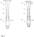
- the filling arrangement 100 In a second step, illustrated in fig. 2 , the filling arrangement 100, still being in the closed state CLOSE, is introduced into the package 200.
- the introduction of the filling arrangement 100 into the package 200 can be achieved by moving the filling arrangement 100 downwards, by moving the package 200 upwards or a combination of the two.
- the filling arrangement 100 is fully inserted into the package 200. Even though being fully inserted, there may be a distance between the filling arrangement 100 and an inside of the package 200 such that the package 200 is not at risk of being damaged by the filling arrangement 100.
- the stem 112 can be moved upwards with respect to the pipe 102 such that the disc-shaped member 116 is placed at a distance D-O from the opening 110, thereby allowing the food product FP to be released from the pipe 102 into the package 200.
- the filling arrangement 100 is moved away from the package 200, by moving the filling arrangement 100, by moving the package 200 or a combination thereof.
- the filling arrangement 100 can be in the open state OPEN.
- An advantage with moving the filling arrangement 100 with respect to the package 200 with the filling arrangement 100 in the open state OPEN is that an efficient filling can be achieved. For instance, splashing and/or foaming can be reduced.
- a fifth step illustrated in fig. 5 , the filling arrangement 100 is moved away from the package 200 and the filling arrangement 100 has entered into the closed state CLOSE, that is, the disc-shaped member 116 is pushed towards the edges 118 of the opening 110.
- CLOSE closed state
- Fig. 6 illustrates the filling arrangement 100 in further detail.
- the edges 118 of the opening 110 may be sharpened, and/or tapered, to assure that the particles ending up between disc-shaped member 116 and the edges 118 when moving from the open state OPEN to the closed state CLOSE can be cut in pieces such that adequate closure of the filling arrangement 100 can be achieved.
- the edges 110 may be inclined downwards. An advantage with having the edges 110 inclined in this way is that the particles can be pushed away from an interface between the disc-shaped member 116 and the edges 118 before the disc-shaped member 116 is closing the opening 110.
- Fig. 7 illustrates a filling station 700 by way of example.
- the filling station 700 can comprise the filling arrangement 100 described above.
- the filling station 700 can comprise a product pipe 702 arranged to provide the food product FP into the pipe 102 of the filling arrangement 100.
- a first motor arrangement 704 can be provided for moving the package 200 with respect to the filling arrangement 100.
- a second arrangement 706 can be provided for moving the stem 112, and also the disc-shaped member 116, with respect to the pipe 102, and also the opening 110.
- a control unit 708 communicatively connected to the first and second motor arrangement 704, 706 can be provided such that control data can be provided to the motor arrangements.
- a conveyor arrangement 710 such as a conveyor belt, can be provided for transporting the package 200.
- the package 200 may, as illustrated, be placed in a package holder 712.
- the package holder 712, holding the package 200 may be moved horizontally to a gripper 714. Once the package holder 712 reaches the gripper 714, the gripper 714 may grip the package holder 712. Once gripped, the package holder 714 with the package 200 can be lifted, by using the first motor arrangement 704 connected to the gripper 714, towards the filling arrangement 100 such that the package 200 can be filled with the food product FP in accordance to the filling procedure illustrated in fig. 1 to fig. 5 .
- Fig. 8 is a flow chart illustrating a method 800 for filling the liquid food product FP comprising particles into the package 200 by using the filing station 700 described above.
- the method can comprise
Landscapes
- Engineering & Computer Science (AREA)
- Mechanical Engineering (AREA)
- Microelectronics & Electronic Packaging (AREA)
- Basic Packing Technique (AREA)
Abstract
A filling arrangement (100) for filling a liquid food product (FP) comprising particles into a package (200). The arrangement comprises
a pipe (102) having a lower section (104) arranged to be fed into a main body (202) of the package (200) during a filling procedure, and an upper section (106) arranged to be placed above the main body (202) during the filling procedure, wherein the lower section (104) has an inner width (W-I), wherein a lower end (108) of the lower section (106) is provided with an opening (110) having an opening width (W-O), wherein the opening width (W-O) is smaller than the inner width (W-I),
a stem (112) arranged to be movable along a center axis (C-A) of the pipe (102), said stem (112) being provided in a lower end (114) with a disc-shaped member (116), wherein a width (W-D) of the disc-shaped member (116) is smaller than the inner width (W-I) of the lower section (108) of the pipe (102) and larger than the opening width (W-O),
wherein the arrangement (110) is configured,
in a closed state (CLOSE), to have the disc-shaped member (116) of the stem (112) pushed towards the opening (110) of the pipe (102) such that the product (FP) is hindered from passing the opening (110), and
in an open state (OPEN), to have the disc-shaped member (116) placed at a distance (D-OS) from the opening (110) such that the product (FP) is released via the opening (110),
wherein edges (118) of the opening (110) are arranged such that the particles of the product (FP) are cut and/or pushed away when the disc-shaped member (116) is pushed towards the opening (110) as the filling arrangement (100) is transferred from the open state (OPEN) to the closed state (CLOSE).
a pipe (102) having a lower section (104) arranged to be fed into a main body (202) of the package (200) during a filling procedure, and an upper section (106) arranged to be placed above the main body (202) during the filling procedure, wherein the lower section (104) has an inner width (W-I), wherein a lower end (108) of the lower section (106) is provided with an opening (110) having an opening width (W-O), wherein the opening width (W-O) is smaller than the inner width (W-I),
a stem (112) arranged to be movable along a center axis (C-A) of the pipe (102), said stem (112) being provided in a lower end (114) with a disc-shaped member (116), wherein a width (W-D) of the disc-shaped member (116) is smaller than the inner width (W-I) of the lower section (108) of the pipe (102) and larger than the opening width (W-O),
wherein the arrangement (110) is configured,
in a closed state (CLOSE), to have the disc-shaped member (116) of the stem (112) pushed towards the opening (110) of the pipe (102) such that the product (FP) is hindered from passing the opening (110), and
in an open state (OPEN), to have the disc-shaped member (116) placed at a distance (D-OS) from the opening (110) such that the product (FP) is released via the opening (110),
wherein edges (118) of the opening (110) are arranged such that the particles of the product (FP) are cut and/or pushed away when the disc-shaped member (116) is pushed towards the opening (110) as the filling arrangement (100) is transferred from the open state (OPEN) to the closed state (CLOSE).
Description
- The invention generally relates to packaging technology. More particularly, it is related to a filling arrangement for filling a liquid food product into a package, a filling station comprising such filling arrangement, and a method related thereto.
- Today, it is increasingly popular to include particles in liquid food products. For instance, during the last couple of years, yoghurt products comprising berries or parts of berries are in many parts of the world a preferred choice instead of plain yoghurt products. Another example of a liquid food product comprising particles are fruit juices comprising pulp and/or seeds.
- Processing liquid food products comprising particles comes with a number of challenges that food producers generally do not face when processing plain products, that is, products not comprising particles. One such challenge is heat treatment. By having the particles, being constituted in different way that than the liquid product itself, there is a risk, if not having equipment and processes being adapted to handle products with particles, that the food product as a whole, that is, both the liquid product and the particles, is not heat treated properly. An effect of this may be that the food product is not safe to consume. Another effect could be that the product properties are negatively affected such that taste, texture etc do not meet expectations of the consumers.
- An example of the liquid food product with particles is aseptic high viscous yoghurt with particles, sometimes referred to as drinking yoghurt. Aseptic yoghurt should herein be understood as that this has been heat treated using so called ultrahigh temperature (UHT) treatment or any other equivalent technology for reducing the number unwanted microorganisms. By doing so and also using a package that can efficiently shield of the food product from the surroundings once packaged, the food product can be stored in room temperature or, in some cases, be stored chilled, but with an extended shelf life.
- An example processing line for producing drinking yoghurt with particles, sometimes referred to as particulates, can comprise a high shear mixer providing for texture and stability of the product, mixing tanks, pasteurizers, an inoculation unit for adding starter culture, a fermentation tank, a cooler to minimize viscosity breakdown, an indirect UHT system for heat treating the product while protecting viscosity, aseptic buffer tanks, a blending tank configured to blend the particulates into the yoghurt, and a packaging machine, such as Tetra Pak® TT/3 AD, which is an example of a carton bottle packaging machine.
- Even though the drinking yoghurt with particles, often having a viscosity of 50-400 cP, can be produced and packaged reliably today, there are challenges related to the particles. One such challenge is that during filling in the packaging machine, there is a risk that particles are caught in a valve mechanism of the filling machine. If this happens, the filing pipe cannot be closed adequately with the effect that there is an increased spillage when moving from one package to another in the packaging machine. A further effect of the spillage is that the particles end up in a sealing area of the packages being filled. If having the particles in the sealing area, there is an increased risk that the package cannot be adequately sealed, sometimes referred to as welded, in a sealing station placed downstream a filling station in the packaging machine.
- It is an object of the invention to at least partly overcome one or more of the above-identified limitations of the prior art. In particular, it is an object to provide a filling mechanism that can handle particles such that adequate closing can be achieved such that in turn less dripping occurs when moving from one package to another.
- According to a first aspect it is provided a filling arrangement for filling a liquid food product comprising particles into a package, said arrangement may comprise
- a pipe having a lower section arranged to be fed into a main body of the package during a filling procedure, and an upper section arranged to be placed above the main body during the filling procedure, wherein the lower section has an inner width, wherein a lower end of the lower section may be provided with an opening having an opening width, wherein the opening width may be smaller than the inner width,
- a stem arranged to be movable along a center axis of the pipe, said stem being provided in a lower end with a disc-shaped member, wherein a width of the disc-shaped member may be smaller than the inner width of the lower section of the pipe and larger than the opening width,
- wherein the arrangement may be configured,
- in a closed state, to have the disc-shaped member of the stem pushed towards the opening of the pipe such that the product is hindered from passing the opening, and
- in an open state, to have the disc-shaped member placed at a distance from the opening such that the product can be released via the opening,
- wherein edges of the opening can be arranged such that the particles of the product are cut and/or pushed away when the disc-shaped member is pushed towards the opening as the filling arrangement is transferred from the open state to the closed state.
- An advantage with having the edges of the opening arranged to cut and/or push away the particles during closing, that is, changing from the open state to the closed state, is that a risk of having the particles stuck between the disc-shaped member and the edges of the opening, thereby reducing dripping, but also reducing wear of the filling arrangement.
- The lower section of the pipe may be have a rectangular cross-section.
- An advantage with this is that a snug fit can be achieved with the package having a rectangular cross-section. An effect of having this snug fit is that less space will be provided between the package and the pipe during the filling procedure, which provides for that a more controlled filling can be achieved.
- The stem may be provided with radially protruding and longitudinally extending guiding members such that a magnitude of horizontal movements between the pipe and the stem during the filling procedure can be reduced.
- Having the guiding members provides for that a risk that the disc-shaped member is misaligned with respect to the opening of the pipe. This in turn provides for that a risk that the disc-shaped member is introduced offset with respect to the opening can be reduced.
- The lower section of the pipe may have a substantially rectangular cross-section, and the stem may be provided with four guiding members, each of them extending into a respective corner of the rectangular cross-section of the lower section of the pipe during the filling procedure.
- By having the pipe provided with the rectangular cross-section such that the snug fit with the package can be achieved and also have the guiding members arranged such that each of these is introduced into a respective corner provides for that reliable guidance can be achieved.
- The pipe may have a substantially rectangular cross-section, and the opening may be a circular opening.
- As described above, having a rectangular cross-section, or substantially rectangular cross-section, provides for that a snug fit with the package can be achieved. Having the opening made circular, even though the pipe is provided with the substantially rectangular cross-section, provides for that a risk of having food product, e.g. the particles, stuck, or entrapped, in the opening can be reduced.
- The disc-shaped member may have a longitudinally rounded side surface, and the edges of the opening may be inclined downwards.
- An advantage with having the disc-shaped member and the edges arranged in this way is that a likelihood of having the particles ending up between the edges and the disc-shaped member can be reduced due to flows formed in the food product as the disc-shaped member is moved towards the edges. Further, in the event that the particles do end up between the edges and the disc-shaped member, these may be cut efficiently.
- The edges of the opening may be tapered.
- An advantage of having the edges tapered is that the particles can be cut in pieces more efficiently.
- A bottom surface of the disc-shaped member may be provided with protrusions and/or dents for reducing dripping in the closed state.
- By having a non-flat surface, an area of the surface may be increased, which may result in that less dripping occur.
- According to a second aspect it is provided a filling station comprising
- a filling arrangement according to the first aspect,
- a product pipe arranged to provide the liquid food product into the pipe of the filing arrangement,
- a first motor arrangement for providing a first relative vertical movement between the filling arrangement and the package,
- a second motor arrangement for providing a second relative vertical movement between the stem and the pipe of the filing arrangement,
- a control unit for controlling the first and second motor arrangement,
- wherein the control unit may be, during the filling procedure, configured
- to move the package relative to the filling arrangement such that the filling arrangement in the closed state is transferred into the package via an open end,
- to move the stem with respect to the pipe by using the second motor arrangement such that the filling arrangement is transferred from the closed state to the open state,
- to move the package relative to the filling arrangement such that the filling arrangement in the open state is transferred away from the package by using the first motor arrangement, and
- to move the stem with respect to the pipe by using the second motor such that the filling arrangement is transferred from the open state to the closed state.
- As described above, the control unit may be configured to move the package relative to the filling arrangement such that the filling arrangement in the closed state is transferred into the package via an open end. The control unit may be set to provide this movement up until a lower end position is reached. Further, as described above, the control unit may be configured to move the package in the open state away from the package. The first arrangement may be set to provide this movement up until a point where a lower end of the pipe of the filling arrangement is outside the package.
- Being able to both control a movement between the package and the filling arrangement and a movement between the stem and the pipe provides for that the filling procedure can be adapted to meet a large variety of different food products with different particles such that efficient filling can be achieved.
- The filling station may further comprise
- a conveyor arrangement arranged to transport at least one package holder holding the package,
- wherein the conveyor arrangement may be configured to intermittently move the package holder such that the package is horizontally held still during the filling procedure.
- The first motor arrangement is arranged to be move the package holder vertically during the filling procedure.
- The first motor arrangement may be arranged to move the package holder solely.
- The second motor arrangement is arranged to move the stem solely.
- According to a third aspect it is provided a method for filling a liquid food product comprising particles into a package by using a filing station according to the second aspect, said method comprising
- moving the package relative to the filling arrangement such that the filling arrangement in the closed state is transferred into the package via an open end by using the first motor arrangement,
- moving the stem with respect to the pipe by using the second motor arrangement such that the filling arrangement is transferred from the closed state to the open state,
- moving the package relative to the filling arrangement such that the filling arrangement in the open state is transferred away from the package by using the first motor arrangement, and
- moving the stem with respect to the pipe by using the second motor such that the filling arrangement is transferred from the open state to the closed state.
- The same features and advantages as described above also apply to this aspect.
- According to a fourth aspect it is provided a computer program product comprising instructions which, when executed by a control unit, cause the control unit to carry out the method according to the third aspect.
- The same features and advantages as described above also apply to this aspect.
- Still other objectives, features, aspects and advantages of the invention will appear from the following detailed description as well as from the drawings.
- Embodiments of the invention will now be described, by way of example, with reference to the accompanying schematic drawings, in which
-
Fig. 1 to fig. 5 illustrate cross-sectional views and perspective views, respectively, of a filling arrangement and a package in different steps of a filling procedure. -
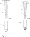
Fig. 6 illustrates a lower end of the filling station in further detail. -
Fig. 7 generally illustrates a filling station comprising the filling arrangement illustrated infig. 1 to 5 . -
Fig. 8 is a flowchart illustrating a method for filling liquid food product comprising particles into the package using the filling arrangement. -
Fig. 1 illustrates by way of example a fillingarrangement 100 comprising apipe 102 having alower section 104 and anupper section 106. Alower end 108 of thepipe 102 is provided with anopening 110. Inside thepipe 102, astem 112 is provided. In alower end 114 of the stem 112 a disc-shapedmember 116 is provided. The disc-shapedmember 116 is arranged such that this has a width W-D. This width W-D is less than an inner width W-I of thepipe 102, but greater than an opening width W-O, that is, the width of theopening 110. By having thestem 112 arranged in this way, theopening 110 of thepipe 102 can be closed by pushing the disc-shapedmember 116 towardsedges 118 of theopening 110. As will be further described below, theedges 118 of theopening 110 may be arranged such that any particles of a food product FP, such as yoghurt, are pushed away from theedges 118 before the disc-shapedmember 116 meet the edges such that thepipe 102 is closed, or in other words enters a closed state CLOSE. In addition or instead, theedges 118 of theopening 110 and the disc-shapedmember 116 may be arranged such that in case the particles end up between theedges 118 and the disc-shapedmember 116, these are cut in parts, thereby providing for that an adequate closing can be made. - As illustrated, the
pipe 102 and thestem 112 may extend along a center axis C-A. Guidingmembers 120 may be provided on thestem 112 such that this can be moved vertically with respect to thepipe 102 without substantially deviating from the center axis C-A. - A
bottom surface 122 of the disc-shapedmember 116 may be provided with dimples, also sometimes referred to as indentations or recesses. By having these, dripping that may occur after the fillingarrangement 100 is closed, that is, transferred from an open state OPEN to the closed state CLOSE, can be reduced. One reason for this is that an area of thebottom surface 122, as an effect of having this provided with dimples, is extended. - During a filling procedure taking place in a filling station, the filling
arrangement 100 can be placed above apackage 200 as illustrated. Thepackage 200 may, as illustrated, comprisemain body 202 and atop section 204. Thepackage 200, exemplified herein, has thetop section 202 placed downwards and a bottom, facing upwards during filling, provided with an open end such that the food product FP can be provided into thepackage 200 via the bottom of thepackage 200. Thepackage 200 may be embodied in various ways. For instance, as illustrated, thetop section 204 may be made of plastic material and also provided with a threaded neck such that a cap can be applied. An example of such package is Tetra Top® marketed by Tetra Pak®. - A filling procedure, sometimes referred to as a filling sequence, taking place in the filling station is illustrated by way of example in
fig. 1 to fig. 5 . In a first step, illustrated infig. 1 , the filling arrangement is in the closed state CLOSE, that is, the disc-shapedmember 116 of thestem 112 is pushed against the opening 110 of thepipe 102 such that the food product FP is hindered from being released via theopening 110 of thepipe 102. - In a second step, illustrated in
fig. 2 , the fillingarrangement 100, still being in the closed state CLOSE, is introduced into thepackage 200. The introduction of the fillingarrangement 100 into thepackage 200 can be achieved by moving the fillingarrangement 100 downwards, by moving thepackage 200 upwards or a combination of the two. - In a third step, illustrated in
fig. 3 , the fillingarrangement 100 is fully inserted into thepackage 200. Even though being fully inserted, there may be a distance between the fillingarrangement 100 and an inside of thepackage 200 such that thepackage 200 is not at risk of being damaged by the fillingarrangement 100. When being fully inserted, thestem 112 can be moved upwards with respect to thepipe 102 such that the disc-shapedmember 116 is placed at a distance D-O from theopening 110, thereby allowing the food product FP to be released from thepipe 102 into thepackage 200. - In a fourth step, illustrated in
fig. 4 , the fillingarrangement 100 is moved away from thepackage 200, by moving the fillingarrangement 100, by moving thepackage 200 or a combination thereof. As the fillingarrangement 100 is moved away from thepackage 200, the fillingarrangement 100 can be in the open state OPEN. An advantage with moving the fillingarrangement 100 with respect to thepackage 200 with the fillingarrangement 100 in the open state OPEN is that an efficient filling can be achieved. For instance, splashing and/or foaming can be reduced. - In a fifth step, illustrated in
fig. 5 , the fillingarrangement 100 is moved away from thepackage 200 and the fillingarrangement 100 has entered into the closed state CLOSE, that is, the disc-shapedmember 116 is pushed towards theedges 118 of theopening 110. By having the fillingarrangement 100 moved away from thepackage 200, thepackage 200, now being filled with the food product FP, can be moved horizontally and be replaced by a new package not yet being filled. -
Fig. 6 illustrates the fillingarrangement 100 in further detail. As illustrated, theedges 118 of theopening 110 may be sharpened, and/or tapered, to assure that the particles ending up between disc-shapedmember 116 and theedges 118 when moving from the open state OPEN to the closed state CLOSE can be cut in pieces such that adequate closure of the fillingarrangement 100 can be achieved. In addition or instead, theedges 110 may be inclined downwards. An advantage with having theedges 110 inclined in this way is that the particles can be pushed away from an interface between the disc-shapedmember 116 and theedges 118 before the disc-shapedmember 116 is closing theopening 110. -
Fig. 7 illustrates a filling station 700 by way of example. As illustrated, the filling station 700 can comprise the fillingarrangement 100 described above. In addition, the filling station 700 can comprise aproduct pipe 702 arranged to provide the food product FP into thepipe 102 of the fillingarrangement 100. Afirst motor arrangement 704 can be provided for moving thepackage 200 with respect to the fillingarrangement 100. Asecond arrangement 706 can be provided for moving thestem 112, and also the disc-shapedmember 116, with respect to thepipe 102, and also theopening 110. Acontrol unit 708 communicatively connected to the first andsecond motor arrangement conveyor arrangement 710, such as a conveyor belt, can be provided for transporting thepackage 200. Thepackage 200 may, as illustrated, be placed in apackage holder 712. Thepackage holder 712, holding thepackage 200, may be moved horizontally to agripper 714. Once thepackage holder 712 reaches thegripper 714, thegripper 714 may grip thepackage holder 712. Once gripped, thepackage holder 714 with thepackage 200 can be lifted, by using thefirst motor arrangement 704 connected to thegripper 714, towards the fillingarrangement 100 such that thepackage 200 can be filled with the food product FP in accordance to the filling procedure illustrated infig. 1 to fig. 5 . -
Fig. 8 is a flow chart illustrating amethod 800 for filling the liquid food product FP comprising particles into thepackage 200 by using the filing station 700 described above. The method can comprise - moving 802 the
package 200 relative to the fillingarrangement 100 such that the fillingarrangement 100 in the closed state CLOSE is transferred into thepackage 200 via an open end by using thefirst motor arrangement 704, - moving 804 the
stem 112 with respect to thepipe 102 by using thesecond motor arrangement 706 such that the fillingarrangement 100 is transferred from the closed state CLOSE to the open state OPEN, - moving 806 the
package 200 relative to the fillingarrangement 100 such that the fillingarrangement 100 in the open state OPEN is transferred away from thepackage 200 by using thefirst motor arrangement 704, and - moving 808 the
stem 112 with respect to thepipe 102 by using thesecond motor 706 such that the fillingarrangement 100 is transferred from the open state OPEN to the closed state CLOSE. - From the description above follows that, although various embodiments of the invention have been described and shown, the invention is not restricted thereto, but may also be embodied in other ways within the scope of the subject-matter defined in the following claims.
Claims (15)
- A filling arrangement (100) for filling a liquid food product (FP) comprising particles into a package (200), said arrangement comprisinga pipe (102) having a lower section (104) arranged to be fed into a main body (202) of the package (200) during a filling procedure, and an upper section (106) arranged to be placed above the main body (202) during the filling procedure, wherein the lower section (104) has an inner width (W-I), wherein a lower end (108) of the lower section (106) is provided with an opening (110) having an opening width (W-O), wherein the opening width (W-O) is smaller than the inner width (W-I),a stem (112) arranged to be movable along a center axis (C-A) of the pipe (102), said stem (112) being provided in a lower end (114) with a disc-shaped member (116), wherein a width (W-D) of the disc-shaped member (116) is smaller than the inner width (W-I) of the lower section (108) of the pipe (102) and larger than the opening width (W-O),wherein the arrangement (110) is configured,in a closed state (CLOSE), to have the disc-shaped member (116) of the stem (112) pushed towards the opening (110) of the pipe (102) such that the product (FP) is hindered from passing the opening (110), andin an open state (OPEN), to have the disc-shaped member (116) placed at a distance (D-OS) from the opening (110) such that the product (FP) is released via the opening (110),wherein edges (118) of the opening (110) are arranged such that the particles of the product (FP) are cut and/or pushed away when the disc-shaped member (116) is pushed towards the opening (110) as the filling arrangement (100) is transferred from the open state (OPEN) to the closed state (CLOSE).
- The filling arrangement (100) according to claim 1, wherein the lower section (108) of the pipe (102) has a rectangular cross-section.
- The filling arrangement (100) according to claim 1 or 2, wherein the stem (112) is provided with radially protruding and longitudinally extending guiding members (120) such that a magnitude of horizontal movements between the pipe (102) and the stem (112) during the filling procedure can be reduced.
- The filling arrangement (100) according to claim 3, wherein the lower section (108) of the pipe (102) has a substantially rectangular cross-section, and wherein the stem (112) is provided with four guiding members (120), each of them extending into a respective corner of the rectangular cross-section of the lower section (108) of the pipe (102) during the filling procedure.
- The filling arrangement (100) according to any one of the preceding claims, wherein the pipe (102) has a substantially rectangular cross-section, and the opening (110) is a circular opening.
- The filling arrangement (100) according to any one of the preceding claims, wherein the disc-shaped member (116) has a longitudinally rounded side surface, and the edges (118) of the opening (110) are inclined downwards.
- The filling arrangement (100) according to any one of the preceding claims, wherein the edges (118) of the opening (110) are tapered.
- The filling arrangement (100) according to any one of the preceding claims, wherein a bottom surface (122) of the disc-shaped member (116) is provided with protrusions and/or dents for reducing dripping in the closed state (CLOSE).
- A filling station (700) comprisinga filling arrangement (100) according to any one of the claims 1 to 8,a product pipe (702) arranged to provide the liquid food product (FP) into the pipe (102) of the filing arrangement (100),a first motor arrangement (704) for providing a first relative vertical movement between the filling arrangement (100) and the package (200),a second motor arrangement (706) for providing a second relative vertical movement between the stem (112) and the pipe (102) of the filing arrangement (100),a control unit (708) for controlling the first and second motor arrangement (704, 706),wherein the control unit (708) is, during the filling procedure, configured to move the package (200) relative to the filling arrangement (100) such that the filling arrangement (100) in the closed state (CLOSE) is transferred into the package (200) via an open end,to move the stem (112) with respect to the pipe (102) by using the second motor arrangement (706) such that the filling arrangement (100) is transferred from the closed state (CLOSE) to the open state (OPEN),to move the package (200) relative to the filling arrangement (100) such that the filling arrangement (100) in the open state (OPEN) is transferred away from the package (200) by using the first motor arrangement (706), andto move the stem (112) with respect to the pipe (102) by using the second motor (708) such that the filling arrangement (100) is transferred from the open state (OPEN) to the closed state (CLOSE).
- The filling station (700) according to claim 9, further comprisinga conveyor arrangement (710) arranged to transport at least one package holder (712) holding the package (200),wherein the conveyor arrangement (710) is configured to intermittently move the package holder (712) such that the package (200) is horizontally held still during the filling procedure.
- The filling station (700) according to claim 10, wherein the first motor arrangement (704) is arranged to be move the package holder (712) vertically during the filling procedure.
- The filling station (700) according to claim 11, wherein the first motor arrangement (704) is arranged to move the package holder (712) solely.
- The filling station (700) according to any one of claim 9 to 12, wherein the second motor arrangement (708) is arranged to move the stem (112) solely.
- A method (800) for filling a liquid food product (FP) comprising particles into a package (200) by using a filing station (700) according to any one of claim 9 to 13, said method comprisingmoving (802) the package (200) relative to the filling arrangement (100) such that the filling arrangement (100) in the closed state (CLOSE) is transferred into the package (200) via an open end by using the first motor arrangement (704),moving (804) the stem (112) with respect to the pipe (102) by using the second motor arrangement (706) such that the filling arrangement (100) is transferred from the closed state (CLOSE) to the open state (OPEN),moving (806) the package (200) relative to the filling arrangement (100) such that the filling arrangement (100) in the open state (OPEN) is transferred away from the package (200) by using the first motor arrangement (704), andmoving (808) the stem (112) with respect to the pipe (102) by using the second motor (706) such that the filling arrangement (100) is transferred from the open state (OPEN) to the closed state (CLOSE).
- A computer program product comprising instructions which, when executed by a control unit (708), cause the control unit (708) to carry out the method according to claim 14.
Applications Claiming Priority (1)
| Application Number | Priority Date | Filing Date | Title |
|---|---|---|---|
| EP23217605 | 2023-12-18 |
Publications (1)
| Publication Number | Publication Date |
|---|---|
| EP4574688A1 true EP4574688A1 (en) | 2025-06-25 |
Family
ID=89223329
Family Applications (1)
| Application Number | Title | Priority Date | Filing Date |
|---|---|---|---|
| EP24214796.5A Pending EP4574688A1 (en) | 2023-12-18 | 2024-11-22 | A filling arrangement, a filling station and a method for filling a liquid food product comprising particles |
Country Status (3)
| Country | Link |
|---|---|
| EP (1) | EP4574688A1 (en) |
| CN (2) | CN223533708U (en) |
| WO (1) | WO2025131546A1 (en) |
Citations (3)
| Publication number | Priority date | Publication date | Assignee | Title |
|---|---|---|---|---|
| US5775387A (en) * | 1996-09-10 | 1998-07-07 | Tetra Laval Holdings & Finance, S. A. | Container filling system having fill-pipe with an extended sealing member for reducing mixing of product and air during container filling |
| US5954086A (en) * | 1996-12-23 | 1999-09-21 | Ronchi Mario S.R.L. | Valve with controlled-action obturator for the metered delivery of fluids in automatic machines for filling containers and the like |
| US20060289078A1 (en) * | 2005-03-04 | 2006-12-28 | Stork Food & Dairy Systems B.V. | Filling valve having a valve body and an essentially cylindrical displacement part |
-
2024
- 2024-11-14 CN CN202422781783.3U patent/CN223533708U/en active Active
- 2024-11-14 CN CN202411625702.9A patent/CN120171824A/en active Pending
- 2024-11-22 WO PCT/EP2024/083278 patent/WO2025131546A1/en active Pending
- 2024-11-22 EP EP24214796.5A patent/EP4574688A1/en active Pending
Patent Citations (3)
| Publication number | Priority date | Publication date | Assignee | Title |
|---|---|---|---|---|
| US5775387A (en) * | 1996-09-10 | 1998-07-07 | Tetra Laval Holdings & Finance, S. A. | Container filling system having fill-pipe with an extended sealing member for reducing mixing of product and air during container filling |
| US5954086A (en) * | 1996-12-23 | 1999-09-21 | Ronchi Mario S.R.L. | Valve with controlled-action obturator for the metered delivery of fluids in automatic machines for filling containers and the like |
| US20060289078A1 (en) * | 2005-03-04 | 2006-12-28 | Stork Food & Dairy Systems B.V. | Filling valve having a valve body and an essentially cylindrical displacement part |
Also Published As
| Publication number | Publication date |
|---|---|
| CN223533708U (en) | 2025-11-11 |
| WO2025131546A1 (en) | 2025-06-26 |
| CN120171824A (en) | 2025-06-20 |
Similar Documents
| Publication | Publication Date | Title |
|---|---|---|
| US20220332558A1 (en) | Apparatus and method for controlled container headspace adjustment | |
| US5758698A (en) | Fill system including a valve assembly and corresponding structure for reducing the mixing of product and air during container filling | |
| EP3225560A1 (en) | Food packaging device | |
| EP3736246A1 (en) | A facility for filling packages in a pressure-sealed chamber and the method of filling | |
| EP3581542B1 (en) | Filling valve and filling machine for filling receptacles | |
| EP0823375B1 (en) | Fill system including a flexible nozzle for reducing the mixing of product and air during container filling | |
| WO2025131546A1 (en) | A filling arrangement, a filling station and a method for filling a liquid food product comprising particles | |
| JPH01235566A (en) | Production of storage stable liquid food | |
| WO2017046134A1 (en) | Method and device for filling a package with a liquid product, and a package containing a liquid product | |
| WO2009004500A1 (en) | Filling valve for a filling machine | |
| US20180244510A1 (en) | Method for aseptic filling of a container, a sterile filling device for said method, and an aseptic machine | |
| US20120090727A1 (en) | Method for filling food containers | |
| EP3227226B1 (en) | Method and apparatus for closing receptacles | |
| EP4257536B1 (en) | An aseptic apparatus for filling and closing aluminium receptacles | |
| EP3659963B1 (en) | Filling plant and method for filling receptacles with a pourable food product | |
| EP2537794A1 (en) | New filling method | |
| US20260097910A1 (en) | Systems and techniques for assembling and introducing cartridges into beverage containers during packaging | |
| US6041576A (en) | Fill system for particulates | |
| US20200385177A1 (en) | Container assemblies including metal closures and thermoplastic containers and methods of hot-filling food and beverage products | |
| WO2024260559A1 (en) | Filling head with single recirculation and flushing conduit | |
| EP2448827B1 (en) | Device for cleaned air provision | |
| EP2537793B1 (en) | New filling method and apparatus therefore | |
| EP4574692A1 (en) | A filling arrangement, a cassette, a system and a method for filling food product into a number of packages | |
| EP2889261A1 (en) | Device for filling a receptacle and filling machine | |
| HK1100032B (en) | Apparatus and method for filling |
Legal Events
| Date | Code | Title | Description |
|---|---|---|---|
| PUAI | Public reference made under article 153(3) epc to a published international application that has entered the european phase |
Free format text: ORIGINAL CODE: 0009012 |
|
| STAA | Information on the status of an ep patent application or granted ep patent |
Free format text: STATUS: THE APPLICATION HAS BEEN PUBLISHED |
|
| AK | Designated contracting states |
Kind code of ref document: A1 Designated state(s): AL AT BE BG CH CY CZ DE DK EE ES FI FR GB GR HR HU IE IS IT LI LT LU LV MC ME MK MT NL NO PL PT RO RS SE SI SK SM TR |
|
| STAA | Information on the status of an ep patent application or granted ep patent |
Free format text: STATUS: REQUEST FOR EXAMINATION WAS MADE |
|
| 17P | Request for examination filed |
Effective date: 20260102 |