EP4574676A1 - Universal vessel mounting system - Google Patents
Universal vessel mounting system Download PDFInfo
- Publication number
- EP4574676A1 EP4574676A1 EP24220967.4A EP24220967A EP4574676A1 EP 4574676 A1 EP4574676 A1 EP 4574676A1 EP 24220967 A EP24220967 A EP 24220967A EP 4574676 A1 EP4574676 A1 EP 4574676A1
- Authority
- EP
- European Patent Office
- Prior art keywords
- flexible strap
- mounting system
- vessel
- hole
- strap
- Prior art date
- Legal status (The legal status is an assumption and is not a legal conclusion. Google has not performed a legal analysis and makes no representation as to the accuracy of the status listed.)
- Pending
Links
Images


Classifications
-
- B—PERFORMING OPERATIONS; TRANSPORTING
- B64—AIRCRAFT; AVIATION; COSMONAUTICS
- B64D—EQUIPMENT FOR FITTING IN OR TO AIRCRAFT; FLIGHT SUITS; PARACHUTES; ARRANGEMENT OR MOUNTING OF POWER PLANTS OR PROPULSION TRANSMISSIONS IN AIRCRAFT
- B64D37/00—Arrangements in connection with fuel supply for power plant
- B64D37/02—Tanks
-
- A—HUMAN NECESSITIES
- A62—LIFE-SAVING; FIRE-FIGHTING
- A62C—FIRE-FIGHTING
- A62C31/00—Delivery of fire-extinguishing material
- A62C31/28—Accessories for delivery devices, e.g. supports
-
- A—HUMAN NECESSITIES
- A62—LIFE-SAVING; FIRE-FIGHTING
- A62C—FIRE-FIGHTING
- A62C3/00—Fire prevention, containment or extinguishing specially adapted for particular objects or places
- A62C3/07—Fire prevention, containment or extinguishing specially adapted for particular objects or places in vehicles, e.g. in road vehicles
- A62C3/08—Fire prevention, containment or extinguishing specially adapted for particular objects or places in vehicles, e.g. in road vehicles in aircraft
-
- B—PERFORMING OPERATIONS; TRANSPORTING
- B60—VEHICLES IN GENERAL
- B60K—ARRANGEMENT OR MOUNTING OF PROPULSION UNITS OR OF TRANSMISSIONS IN VEHICLES; ARRANGEMENT OR MOUNTING OF PLURAL DIVERSE PRIME-MOVERS IN VEHICLES; AUXILIARY DRIVES FOR VEHICLES; INSTRUMENTATION OR DASHBOARDS FOR VEHICLES; ARRANGEMENTS IN CONNECTION WITH COOLING, AIR INTAKE, GAS EXHAUST OR FUEL SUPPLY OF PROPULSION UNITS IN VEHICLES
- B60K15/00—Arrangement in connection with fuel supply of combustion engines or other fuel consuming energy converters, e.g. fuel cells; Mounting or construction of fuel tanks
- B60K15/03—Fuel tanks
- B60K15/063—Arrangement of tanks
- B60K15/067—Mounting of tanks
-
- B—PERFORMING OPERATIONS; TRANSPORTING
- B60—VEHICLES IN GENERAL
- B60K—ARRANGEMENT OR MOUNTING OF PROPULSION UNITS OR OF TRANSMISSIONS IN VEHICLES; ARRANGEMENT OR MOUNTING OF PLURAL DIVERSE PRIME-MOVERS IN VEHICLES; AUXILIARY DRIVES FOR VEHICLES; INSTRUMENTATION OR DASHBOARDS FOR VEHICLES; ARRANGEMENTS IN CONNECTION WITH COOLING, AIR INTAKE, GAS EXHAUST OR FUEL SUPPLY OF PROPULSION UNITS IN VEHICLES
- B60K15/00—Arrangement in connection with fuel supply of combustion engines or other fuel consuming energy converters, e.g. fuel cells; Mounting or construction of fuel tanks
- B60K15/03—Fuel tanks
- B60K15/063—Arrangement of tanks
- B60K15/067—Mounting of tanks
- B60K15/07—Mounting of tanks of gas tanks
-
- F—MECHANICAL ENGINEERING; LIGHTING; HEATING; WEAPONS; BLASTING
- F17—STORING OR DISTRIBUTING GASES OR LIQUIDS
- F17C—VESSELS FOR CONTAINING OR STORING COMPRESSED, LIQUEFIED OR SOLIDIFIED GASES; FIXED-CAPACITY GAS-HOLDERS; FILLING VESSELS WITH, OR DISCHARGING FROM VESSELS, COMPRESSED, LIQUEFIED, OR SOLIDIFIED GASES
- F17C13/00—Details of vessels or of the filling or discharging of vessels
- F17C13/08—Mounting arrangements for vessels
- F17C13/084—Mounting arrangements for vessels for small-sized storage vessels, e.g. compressed gas cylinders or bottles, disposable gas vessels, vessels adapted for automotive use
-
- A—HUMAN NECESSITIES
- A62—LIFE-SAVING; FIRE-FIGHTING
- A62C—FIRE-FIGHTING
- A62C35/00—Permanently-installed equipment
- A62C35/02—Permanently-installed equipment with containers for delivering the extinguishing substance
-
- B—PERFORMING OPERATIONS; TRANSPORTING
- B60—VEHICLES IN GENERAL
- B60P—VEHICLES ADAPTED FOR LOAD TRANSPORTATION OR TO TRANSPORT, TO CARRY, OR TO COMPRISE SPECIAL LOADS OR OBJECTS
- B60P7/00—Securing or covering of load on vehicles
- B60P7/06—Securing of load
- B60P7/08—Securing to the vehicle floor or sides
- B60P7/0823—Straps; Tighteners
-
- F—MECHANICAL ENGINEERING; LIGHTING; HEATING; WEAPONS; BLASTING
- F17—STORING OR DISTRIBUTING GASES OR LIQUIDS
- F17C—VESSELS FOR CONTAINING OR STORING COMPRESSED, LIQUEFIED OR SOLIDIFIED GASES; FIXED-CAPACITY GAS-HOLDERS; FILLING VESSELS WITH, OR DISCHARGING FROM VESSELS, COMPRESSED, LIQUEFIED, OR SOLIDIFIED GASES
- F17C2205/00—Vessel construction, in particular mounting arrangements, attachments or identifications means
- F17C2205/01—Mounting arrangements
- F17C2205/0153—Details of mounting arrangements
- F17C2205/0188—Hanging up devices
-
- F—MECHANICAL ENGINEERING; LIGHTING; HEATING; WEAPONS; BLASTING
- F17—STORING OR DISTRIBUTING GASES OR LIQUIDS
- F17C—VESSELS FOR CONTAINING OR STORING COMPRESSED, LIQUEFIED OR SOLIDIFIED GASES; FIXED-CAPACITY GAS-HOLDERS; FILLING VESSELS WITH, OR DISCHARGING FROM VESSELS, COMPRESSED, LIQUEFIED, OR SOLIDIFIED GASES
- F17C2221/00—Handled fluid, in particular type of fluid
- F17C2221/01—Pure fluids
- F17C2221/011—Oxygen
-
- F—MECHANICAL ENGINEERING; LIGHTING; HEATING; WEAPONS; BLASTING
- F17—STORING OR DISTRIBUTING GASES OR LIQUIDS
- F17C—VESSELS FOR CONTAINING OR STORING COMPRESSED, LIQUEFIED OR SOLIDIFIED GASES; FIXED-CAPACITY GAS-HOLDERS; FILLING VESSELS WITH, OR DISCHARGING FROM VESSELS, COMPRESSED, LIQUEFIED, OR SOLIDIFIED GASES
- F17C2223/00—Handled fluid before transfer, i.e. state of fluid when stored in the vessel or before transfer from the vessel
- F17C2223/01—Handled fluid before transfer, i.e. state of fluid when stored in the vessel or before transfer from the vessel characterised by the phase
- F17C2223/0107—Single phase
- F17C2223/0123—Single phase gaseous, e.g. CNG, GNC
-
- F—MECHANICAL ENGINEERING; LIGHTING; HEATING; WEAPONS; BLASTING
- F17—STORING OR DISTRIBUTING GASES OR LIQUIDS
- F17C—VESSELS FOR CONTAINING OR STORING COMPRESSED, LIQUEFIED OR SOLIDIFIED GASES; FIXED-CAPACITY GAS-HOLDERS; FILLING VESSELS WITH, OR DISCHARGING FROM VESSELS, COMPRESSED, LIQUEFIED, OR SOLIDIFIED GASES
- F17C2223/00—Handled fluid before transfer, i.e. state of fluid when stored in the vessel or before transfer from the vessel
- F17C2223/03—Handled fluid before transfer, i.e. state of fluid when stored in the vessel or before transfer from the vessel characterised by the pressure level
- F17C2223/036—Very high pressure (>80 bar)
Definitions
- the present invention relates to a mounting system for vehicle-borne vessels, and more particularly to a mounting system for aviation fire extinguisher vessels.
- a vessel mounting system for a vehicle includes a first flexible strap configured to circumscribe the vessel in a first direction, a second flexible strap configured to circumscribe the vessel in a second direction such that the second flexible strap and the first flexible strap overlap in at least one location, a strap mating coupler securing the first flexible strap to the second flexible at the at least one location, and at least one coupling device connected to the first flexible strap configured to mate with a structure on the vehicle.
- Each of the first flexible strap and the second flexible strap includes a plurality of clamp sleeves connected in an end-to-end manner.
- a method of mounting a vessel to a structure in a vehicle using a mounting system includes circumscribing the vessel with a first flexible strap in a first direction along the vessel, circumscribing the vessel with a second flexible strap in a second direction non-parallel to the first direction, and connecting at least one coupling device extending from the first flexible strap to a structure of the vehicle.
- mounting systems described herein need not be limited to aviation and/or fire suppression applications, for example, with utility in other types of vehicles (e.g., marine, terrestrial, etc.), as well as non-fire extinguishing pressure vessels, such as oxygen tanks for an aircraft's oxygen system, and/or the compressed gas cylinders used for inflating escape slides.
- FIGS. 1A and 2B are simplified illustrations showing, respectively, vessel 10A supported by mounting system 12A and vessel 10B supported by mounting system 12B.
- Vessel 10A is a spherical pressure vessel and vessel 10B is a cylindrical pressure vessel, each of which can contain one or a combination of fire extinguishing/suppressing agents.
- agents can be expelled from outlet nozzles 14A, 14B, which are preferably disposed at the gravitational bottom of vessels 10A and 10B, respectively, when mounted to permit optimal discharge of the agent(s) when activated.
- Mounting system 12A can include at least two flexible support straps 16A, each of which can be adjustable to circumscribe vessel 10A in the desired direction, as is discussed in greater detail below. At least one strap mating coupler 18A releasably secures straps 16A to one another in at least one overlapping location of straps 16A.
- Lugs 20A can be attached to strap 16A to support vessel 10A upon and attach to bracket 22A, which can be an aircraft-based structure attached to bulkhead 24A, or other load-bearing structure (e.g., rail, column, etc.).
- bracket 22A which can be an aircraft-based structure attached to bulkhead 24A, or other load-bearing structure (e.g., rail, column, etc.).
- lugs are attached to the vessel, (e.g., via welding), and the weight of the vessel is borne upon the lugs as concentrated point loads.
- Lug couplers 50 with lugs 20 and/or brackets 58 can be attached to clamp sleeves 28 wherever the respective strap 16 needs to interface with/attach to an external support structure.
- At least one additional strap 16 can be similarly assembled and sized to circumscribe the vessel in a different (i.e., non-parallel) direction. In some cases, the straps will have different lengths (i.e., L2 of FIG. 2 ), such as with a vessel longer in one direction (e.g., vessel 10B of FIG. 1B ). Straps 16 can then be secured around the vessel by securing together the free ends 36, 38 of each strap 16. Straps 16 can then be secured together at overlapping points using strap mating couplers.
- the various lugs 20 and/or brackets 58 can then be used to secure the vessel to the external support structure of the aircraft.
- System 12 can be applied to different vessel configurations and is not unique to a single vessel mounting configuration.
- the vessel installers/maintainers can utilize the common mounting kits for multiple different vessel configurations to permit economic installations that are significantly cost reduced and stronger than the current vessel fixed lug mounting approaches.
- a vessel mounting system for a vehicle includes a first flexible strap configured to circumscribe the vessel in a first direction, a second flexible strap configured to circumscribe the vessel in a second direction such that the second flexible strap and the first flexible strap overlap in at least one location, a strap mating coupler securing the first flexible strap to the second flexible at the at least one location, and at least one coupling device connected to the first flexible strap configured to mate with a structure on the vehicle.
- Each of the first flexible strap and the second flexible strap includes a plurality of clamp sleeves connected in an end-to-end manner.
- the mounting system of the preceding paragraph can optionally include, additionally and/or alternatively, any one or more of the following features, configurations and/or additional components:
- each of the plurality of clamps sleeves can include a first side including a longitudinally extending boss region and a lip on each side of the boss region, and an opposing side.
- a plurality of holes can extend through the boss region from the first side to the second side.
- any of the above mounting systems can further include one of a plurality of countersinks in the second side aligning with respective ones of the plurality of holes, and a plurality of counterbores in the second side aligning with respective ones of the plurality of holes.
- any of the above mounting systems can further include a first track mating coupler connecting a first of the plurality of clamp sleeves to a second of the plurality of clamp sleeves, the coupler having a first hole aligned with a hole of the first clamp sleeve and a second hole aligned with a hole of the second clamp sleeve, and a bolt extending through each of the first hole and the second hole.
- any of the above mounting systems can further include a second track mating coupler connecting a third of the plurality of clamp sleeves to the second of the plurality of clamp sleeves, the coupler having a first hole aligned with a hole of the second clamp sleeve and a second hole aligned with a hole of the third clamp sleeve, and a bolt extending through each of the first hole and the second hole.
- the coupling device connected to the first flexible strap can be a lug.
- Any of the above mounting systems can further include a planar lug coupler extending across the boss region and retained by each lip.
- a hole in the lug coupler can align with one of the plurality of holes in the clamp sleeve, and the lug can extend through the one of the plurality of holes in the clamp sleeve and the hole in the lug coupler.
- any of the above mounting systems can further include at least one additional coupling device connected to the first flexible strap or the second flexible strap and configured to mate with a structure on the vehicle.
- the at least one additional coupling device can be a lug.
- the at least one additional coupling device can be a bracket.
- each of the plurality of clamp sleeves can be formed from one of a metallic material and a composite material.
- each of the plurality of clamp sleeves can further include a polymeric material on the second side.
- the first direction of the first flexible strap can be non-parallel to the second direction of the second flexible strap.
- the first flexible strap can have a first length
- the second flexible strap can have a second length
- the first length can be different than the second length.
- a method of mounting a vessel to a structure in a vehicle using a mounting system includes circumscribing the vessel with a first flexible strap in a first direction along the vessel, circumscribing the vessel with a second flexible strap in a second direction non-parallel to the first direction, and connecting at least one coupling device extending from the first flexible strap to a structure of the vehicle.
- the method of the preceding paragraph can optionally include, additionally and/or alternatively, any one or more of the following features, configurations and/or additional steps:
- Any of the above methods can further include assembling each of the first flexible strap and the second flexible strap by connecting a plurality of clamp sleeves in an end-to-end manner.
- Any of the above methods can further include securing the first flexible strap to the second flexible strap in at least one overlapping location using a strap mating coupler.
- the first flexible strap can have a first length
- the second flexible strap can have a second length
- the first length can be different than the second length.
Landscapes
- Engineering & Computer Science (AREA)
- Emergency Management (AREA)
- Mechanical Engineering (AREA)
- Health & Medical Sciences (AREA)
- Public Health (AREA)
- Business, Economics & Management (AREA)
- Sustainable Development (AREA)
- Life Sciences & Earth Sciences (AREA)
- Sustainable Energy (AREA)
- Chemical & Material Sciences (AREA)
- Combustion & Propulsion (AREA)
- Transportation (AREA)
- General Engineering & Computer Science (AREA)
- Aviation & Aerospace Engineering (AREA)
- Clamps And Clips (AREA)
Abstract
Description
- The present invention relates to a mounting system for vehicle-borne vessels, and more particularly to a mounting system for aviation fire extinguisher vessels.
- Aviation fire extinguisher vessels are traditionally mounted to aircraft structures using secondary mounting plates and vessel-attached mounting lugs. Although considered suitable for the intended purpose, in such mounting systems, the vessel-attached lugs bear a majority of the vessel's weight. Furthermore, the mounting hardware can require the vessel to be oriented at a non-optimal discharge angle. As such, improved mounting systems are desirable.
- A vessel mounting system for a vehicle includes a first flexible strap configured to circumscribe the vessel in a first direction, a second flexible strap configured to circumscribe the vessel in a second direction such that the second flexible strap and the first flexible strap overlap in at least one location, a strap mating coupler securing the first flexible strap to the second flexible at the at least one location, and at least one coupling device connected to the first flexible strap configured to mate with a structure on the vehicle. Each of the first flexible strap and the second flexible strap includes a plurality of clamp sleeves connected in an end-to-end manner.
- A method of mounting a vessel to a structure in a vehicle using a mounting system includes circumscribing the vessel with a first flexible strap in a first direction along the vessel, circumscribing the vessel with a second flexible strap in a second direction non-parallel to the first direction, and connecting at least one coupling device extending from the first flexible strap to a structure of the vehicle.
-
-
FIG. 1A is a simplified illustration of a first vessel supported by a first mounting system. -
FIG. 1B is a simplified illustration of a second vessel supported by a substantially similar second mounting system. -
FIG. 2 is a simplified illustration of a flexible strap belonging to a mounting system, such as the mounting systems ofFIGS. 1A and 1B . -
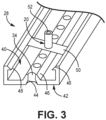
FIG. 3 is a perspective cross-sectional view of a clamp sleeve belonging to the flexible strap ofFIG. 2 . -
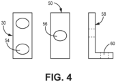
FIG. 4 is a simplified illustration of mounting hardware of a mounting system, such as the mounting system ofFIGS. 1A and 1B . - While the above-identified figures set forth one or more embodiments of the present disclosure, other embodiments are also contemplated, as noted in the discussion. In all cases, this disclosure presents the invention by way of representation and not limitation. It should be understood that numerous other modifications and embodiments can be devised by those skilled in the art, which fall within the scope and spirit of the principles of the invention. The figures may not be drawn to scale, and applications and embodiments of the present invention may include features and components not specifically shown in the drawings.
- Federal aviation regulations require fire extinguishers and fixed fire systems throughout an aircraft. However, traditional halon-based systems are being phased out in favor of low or zero ODP (ozone depletion potential) agents. Such agents often require larger, heavy vessels than halon. Furthermore, some new aircraft designs have fewer load-bearing structures to which vessels can be attached. Accordingly, the disclosure presents a universal mounting system for use with various fire suppression vessels in both existing and future aircraft designs, as the mounting systems are highly customizable to the vessel. It is worth noting that the mounting systems described herein need not be limited to aviation and/or fire suppression applications, for example, with utility in other types of vehicles (e.g., marine, terrestrial, etc.), as well as non-fire extinguishing pressure vessels, such as oxygen tanks for an aircraft's oxygen system, and/or the compressed gas cylinders used for inflating escape slides.
-
FIGS. 1A and 2B are simplified illustrations showing, respectively,vessel 10A supported bymounting system 12A andvessel 10B supported bymounting system 12B. Vessel 10A is a spherical pressure vessel andvessel 10B is a cylindrical pressure vessel, each of which can contain one or a combination of fire extinguishing/suppressing agents. Such agents can be expelled fromoutlet nozzles vessels -
Mounting system 12A can include at least twoflexible support straps 16A, each of which can be adjustable to circumscribevessel 10A in the desired direction, as is discussed in greater detail below. At least onestrap mating coupler 18A releasably securesstraps 16A to one another in at least one overlapping location ofstraps 16A.Lugs 20A can be attached tostrap 16A to supportvessel 10A upon and attach tobracket 22A, which can be an aircraft-based structure attached tobulkhead 24A, or other load-bearing structure (e.g., rail, column, etc.). In some existing mounting systems, lugs are attached to the vessel, (e.g., via welding), and the weight of the vessel is borne upon the lugs as concentrated point loads. Over time, these point loads can compromise the vessel's integrity (e.g., causing cracks at the welds), causing damage and/or rendering the vessel inoperable. However, insystem 12A,lugs 20A are attached tostrap 16A, such that these loads are not placed onvessel 10A. Furthermore, the combinations oflugs 20A and multiple interconnectedstraps 16A supportsvessel 10A in each of the x, y, and z directions, thereby distributing the loads and reducing the vessel fatigue risk.Adapting system 12A such thatlugs 20A are attached tostraps 16A instead of fixed points onvessel 10A allowsvessel 10A to be optimally restrained to the surrounding aircraft structure. Vessel 10A can therefore be designed with minimal wall thickness (thereby minimizing weight) based on its size and the type of agent contained within, since it need not have welds for attachment oflugs 20A. Finally, should anylug 20A be damaged, it can easily be replaced with no loss of functionality of the moreexpensive vessel 10A. -
Mounting system 12B is substantially similar tomounting system 12A, having one ormore straps 16Bcircumscribing vessel 10B, strap mating coupler(s) 18B,lugs 20B attached to the horizontally disposed (i.e., along the x-axis)strap 16B to supportvessel 10B uponbracket 22B which is attached tobulkhead 24B.System 12B differs slightly in that, because of theadditional bracket 22B abovevessel 10B, alug 20B is also attached to the vertically extendingstrap 16B to securevessel 10B to thesecond bracket 22B.Such lug 20B can alternatively be a hook in another embodiment.System 12B also supports 10B in each of the x, y, and z directions. It is also worth mentioning thatstraps vessels nozzles vessels nozzles grounding wires system vessels systems -
FIG. 2 is a simplifiedillustration showing strap 16 ofmounting system 12, which can be substantially similar tostraps mounting systems Strap 16 can be formed frommultiple clamp sleeves 28, each which can be arranged in an end-to-end manner and attached to each neighboringclamp sleeve 28 using track coupler 30 (represented in transparency by dashed lines) andbolts 32. Eachclamp sleeve 28 includes a number ofholes 34 extending completely through, in most cases, the thickness ofclamp sleeve 28.Holes 34 can be used to interconnect various couplers to arespective clamp sleeve 28, as is discussed in greater detail below. Eachclamp sleeve 28 can further have a length L1 and a width W. Length L1 can generally range from 2 in (50.8 mm) to 12 in (304.8 mm), and can more specifically be 2 in, 3 in (76.2 mm), or 6 in (152.4 mm) in some embodiments. In general, any number from two ton clamp sleeves 28 of uniform or varied lengths L1 can be attached to form astrap 16 with the desired overall length L2 ofstrap 16. Width W can nominally be 2 in, but greater widths (e.g., 3 in) can be used with larger and/or heavier vessels. Eachclamp sleeve 28 can have opposing first andsecond ends concave end 36 and aconvex end 38, withconcave end 36 being configured to mate with aconvex end 38 of anadjacent clamp sleeve 28, and convexend 38 being configured to mate with aconcave end 38 of anotheradjacent clamp sleeve 28. Further,strap 16 can be made to fully circumscribe a vessel (e.g., 10A or 10B) by mating theconcave end 36 of oneoutermost clamp sleeve 28 to the convex end of the opposingoutermost clamp sleeve 28, such thatstrap 16 forms an enclosed loop.End 36 and/or 38 can be straight or have some kind of male-female configuration in alternative embodiments. -
FIG. 3 is a perspective cross-sectional view of a portion of anindividual clamp sleeve 28 showing first, external (i.e., outward facing)side 40 in greater detail.Clamp sleeve 28 can be formed from a lightweight flexible material such as a metallic material (e.g., steel) or a composite material (e.g., Kevlar). Second, internal (i.e., vessel facing)side 42 can be generally planar/flat and can include countersinks (or counterbores) 44 aligned withrespective holes 34, allowing the various fasteners (e.g.,bolts 32,lugs 20. etc.) to sit inward of the surface ofinternal side 42. This is preferable to prevent contact between the fasteners and the supported vessel (e.g., 10A or 10B).Internal side 42 can further include a polymeric coating to create friction between the vessel andinternal side 42 for a secure fit betweenstrap 16 and the vessel. -
External side 40 includes longitudinally extendingboss region 46 in which holes 34 are formed.External side 40 further includes alongitudinally extending lip 48 on each side ofboss region 46.Lips 48 andboss region 46 cooperate to retain various mounting hardware. For example,FIG. 3 shows lugcoupler 50 and lug 20 (substantially similar tolugs sleeve 28.Lug coupler 50 can be inserted intoexternal side 40 such that it overlaps with and is retained bylips 48.Lug coupler 50 includes a hole (shown and labeled inFIG. 4 ) which is aligned with a desiredhole 34 inclamp sleeve 28 at a location wherestrap 16 is expected to meet with an aircraft structure (e.g.,bracket lug 20 can be inserted to mate with the aircraft structure. Accordingly, lug 20 can includehole 52 which can be aligned with a hole in the aircraft structure, and through which a fastener can be inserted. -
FIG. 4 is a simplified illustration of various mounting hardware that can be used withclamps sleeves 28. Beginning from the left is track coupler 30 (also shown inFIG. 2 ) used to couple twoclamp sleeves 28.Track coupler 30 is planar with at least twoholes 54, one of each aligning with ahole 34 on eachclamp sleeve 28 for receivingbolts 32. At the center islug coupler 50 which is similarly planar and has at least onehole 56 for aligning with ahole 34 ofclamp sleeve 28 and through which lug 20 or other suitable coupling device can be inserted. On the right is an L-shapedbracket 58 havingholes 60, one of which can align with ahole 34 onclamps sleeve 28 and the other of which can align with a hole on the external mounting structure.Bracket 58 can be used in addition to, or instead oflug coupler 50 and lug 20 depending on the type and/or position of external support structure available.Bracket 58 need not be L-shaped in an alternative embodiment.Track coupler 30,lug coupler 50, andbracket 58 can all be formed from a metallic material (e.g., stainless steel). - Mounting
system 12 can be packaged as a kit includingmultiple clamp sleeves 28 of various lengths,multiple track couplers 30 and bolts 32 (including matching nuts and washers),multiple lug couplers 50 and lugs 20,multiple brackets 58, multiple strap mating couplers (shown inFIGS 1A and 1B as 18A and 18B), and at least one grounding wire (shown inFIGS. 1A and 1B as 26A and 26B). To assemble mountingsystem 12, the user can, from such a kit, select the desired number and length ofclamp sleeves 28 needed to circumscribe a particular vessel in one direction. The selected clampssleeves 28 can be assembled end-to-end usingtrack couplers 30 andbolts 32 to form astrap 16.Lug couplers 50 withlugs 20 and/orbrackets 58 can be attached to clampsleeves 28 wherever therespective strap 16 needs to interface with/attach to an external support structure. At least oneadditional strap 16 can be similarly assembled and sized to circumscribe the vessel in a different (i.e., non-parallel) direction. In some cases, the straps will have different lengths (i.e., L2 ofFIG. 2 ), such as with a vessel longer in one direction (e.g.,vessel 10B ofFIG. 1B ).Straps 16 can then be secured around the vessel by securing together the free ends 36, 38 of eachstrap 16.Straps 16 can then be secured together at overlapping points using strap mating couplers. Thevarious lugs 20 and/orbrackets 58 can then be used to secure the vessel to the external support structure of the aircraft.System 12 can be applied to different vessel configurations and is not unique to a single vessel mounting configuration. Thus, the vessel installers/maintainers can utilize the common mounting kits for multiple different vessel configurations to permit economic installations that are significantly cost reduced and stronger than the current vessel fixed lug mounting approaches. - The following are non-exclusive descriptions of possible embodiments of the present invention.
- A vessel mounting system for a vehicle includes a first flexible strap configured to circumscribe the vessel in a first direction, a second flexible strap configured to circumscribe the vessel in a second direction such that the second flexible strap and the first flexible strap overlap in at least one location, a strap mating coupler securing the first flexible strap to the second flexible at the at least one location, and at least one coupling device connected to the first flexible strap configured to mate with a structure on the vehicle. Each of the first flexible strap and the second flexible strap includes a plurality of clamp sleeves connected in an end-to-end manner.
- The mounting system of the preceding paragraph can optionally include, additionally and/or alternatively, any one or more of the following features, configurations and/or additional components:
- In the above mounting system, each of the plurality of clamps sleeves can include a first side including a longitudinally extending boss region and a lip on each side of the boss region, and an opposing side. A plurality of holes can extend through the boss region from the first side to the second side.
- Any of the above mounting systems can further include one of a plurality of countersinks in the second side aligning with respective ones of the plurality of holes, and a plurality of counterbores in the second side aligning with respective ones of the plurality of holes.
- Any of the above mounting systems can further include a first track mating coupler connecting a first of the plurality of clamp sleeves to a second of the plurality of clamp sleeves, the coupler having a first hole aligned with a hole of the first clamp sleeve and a second hole aligned with a hole of the second clamp sleeve, and a bolt extending through each of the first hole and the second hole.
- Any of the above mounting systems can further include a second track mating coupler connecting a third of the plurality of clamp sleeves to the second of the plurality of clamp sleeves, the coupler having a first hole aligned with a hole of the second clamp sleeve and a second hole aligned with a hole of the third clamp sleeve, and a bolt extending through each of the first hole and the second hole.
- In any of the above mounting systems, the coupling device connected to the first flexible strap can be a lug.
- Any of the above mounting systems can further include a planar lug coupler extending across the boss region and retained by each lip. A hole in the lug coupler can align with one of the plurality of holes in the clamp sleeve, and the lug can extend through the one of the plurality of holes in the clamp sleeve and the hole in the lug coupler.
- Any of the above mounting systems can further include at least one additional coupling device connected to the first flexible strap or the second flexible strap and configured to mate with a structure on the vehicle.
- In any of the above mounting systems, the at least one additional coupling device can be a lug.
- In any of the above mounting systems, the at least one additional coupling device can be a bracket.
- In any of the above mounting systems, each of the plurality of clamp sleeves can be formed from one of a metallic material and a composite material.
- In any of the above mounting systems, each of the plurality of clamp sleeves can further include a polymeric material on the second side.
- In any of the above mounting systems, the first direction of the first flexible strap can be non-parallel to the second direction of the second flexible strap.
- In any of the above mounting systems, the first flexible strap can have a first length, and the second flexible strap can have a second length.
- In any of the above mounting systems, the first length can be different than the second length.
- A method of mounting a vessel to a structure in a vehicle using a mounting system includes circumscribing the vessel with a first flexible strap in a first direction along the vessel, circumscribing the vessel with a second flexible strap in a second direction non-parallel to the first direction, and connecting at least one coupling device extending from the first flexible strap to a structure of the vehicle.
- The method of the preceding paragraph can optionally include, additionally and/or alternatively, any one or more of the following features, configurations and/or additional steps:
- Any of the above methods can further include assembling each of the first flexible strap and the second flexible strap by connecting a plurality of clamp sleeves in an end-to-end manner.
- Any of the above methods can further include securing the first flexible strap to the second flexible strap in at least one overlapping location using a strap mating coupler.
- In any of the above methods, the first flexible strap can have a first length, and the second flexible strap can have a second length.
- In any of the above methods, the first length can be different than the second length.
- While the invention has been described with reference to an exemplary embodiment(s), it will be understood by those skilled in the art that various changes may be made and equivalents may be substituted for elements thereof without departing from the scope of the invention. In addition, many modifications may be made to adapt a particular situation or material to the teachings of the invention without departing from the essential scope thereof. Therefore, it is intended that the invention not be limited to the particular embodiment(s) disclosed, but that the invention will include all embodiments falling within the scope of the appended claims.
Claims (15)
- A vessel mounting system for a vehicle, the mounting system comprising:a first flexible strap configured to circumscribe the vessel in a first direction;a second flexible strap configured to circumscribe the vessel in a second direction such that the second flexible strap and the first flexible strap overlap in at least one location;a strap mating coupler securing the first flexible strap to the second flexible at the at least one location; andat least one coupling device connected to the first flexible strap configured to mate with a structure on the vehicle,wherein each of the first flexible strap and the second flexible strap comprises: a plurality of clamp sleeves connected in an end-to-end manner.
- The mounting system of claim 1, wherein each of the plurality of clamp sleeves comprises:a first side comprising:a longitudinally extending boss region; anda lip on each side of the boss region; andan opposing second side,wherein a plurality of holes extend through the boss region from the first side to the second side.
- The mounting system of claim 2, and further comprising one of:a plurality of countersinks in the second side aligning with respective ones of the plurality of holes; anda plurality of counterbores in the second side aligning with respective ones of the plurality of holes.
- The mounting system of claim 2 or 3, and further comprising:a first track mating coupler connecting a first of the plurality of clamp sleeves to a second of the plurality of clamp sleeves, the coupler having a first hole aligned with a hole of the first clamp sleeve and a second hole aligned with a hole of the second clamp sleeve; anda bolt extending through each of the first hole and the second hole.
- The mounting system of claim 4, and further comprising:a second track mating coupler connecting a third of the plurality of clamp sleeves to the second of the plurality of clamp sleeves, the coupler having a first hole aligned with a hole of the second clamp sleeve and a second hole aligned with a hole of the third clamp sleeve; anda bolt extending through each of the first hole and the second hole.
- The mounting system of any one of claims 2-5, wherein the coupling device connected to the first flexible strap is a lug; and wherein the mounting system further comprises:a planar lug coupler extending across the boss region and retained by each lip,wherein a hole in the lug coupler aligns with one of the plurality of holes in the clamp sleeve; andwherein the lug extends through the one of the plurality of holes in the clamp sleeve and the hole in the lug coupler.
- The mounting system of claim 6, and further comprising:
at least one additional coupling device connected to the first flexible strap or the second flexible strap and configured to mate with a structure on the vehicle. - The mounting system of claim 7, wherein the at least one additional coupling device is a lug and/or a bracket.
- The mounting system of any one of claims 2-8, wherein each of the plurality of clamp sleeves is formed from one of:a metallic material; anda composite material.
- The mounting system of claim 9, wherein each of the plurality of clamp sleeves further comprises:
a polymeric material on the second side. - The mounting system of any preceding claim, wherein the first direction of the first flexible strap is non-parallel to the second direction of the second flexible strap.
- The mounting system of any preceding claim, wherein the first flexible strap has a first length, and wherein the second flexible strap has a second length; optionally wherein the first length is different than the second length.
- A method of mounting a vessel to a structure in a vehicle using a mounting system, the method comprising:circumscribing the vessel with a first flexible strap in a first direction along the vessel;circumscribing the vessel with a second flexible strap in a second direction non-parallel to the first direction; andconnecting at least one coupling device extending from the first flexible strap to a structure of the vehicle.
- The method of claim 13 and further comprising: assembling each of the first flexible strap and the second flexible strap by connecting a plurality of clamp sleeves in an end-to-end manner.
- The method of claim 13 or 14, and further comprising securing the first flexible strap to the second flexible strap in at least one overlapping location using a strap mating coupler; and/or wherein the first flexible strap has a first length, and wherein the second flexible strap has a second length that is different than the first length.
Applications Claiming Priority (1)
| Application Number | Priority Date | Filing Date | Title |
|---|---|---|---|
| US18/545,009 US20250195928A1 (en) | 2023-12-19 | 2023-12-19 | Universal vessel mounting system |
Publications (1)
| Publication Number | Publication Date |
|---|---|
| EP4574676A1 true EP4574676A1 (en) | 2025-06-25 |
Family
ID=93925841
Family Applications (1)
| Application Number | Title | Priority Date | Filing Date |
|---|---|---|---|
| EP24220967.4A Pending EP4574676A1 (en) | 2023-12-19 | 2024-12-18 | Universal vessel mounting system |
Country Status (2)
| Country | Link |
|---|---|
| US (1) | US20250195928A1 (en) |
| EP (1) | EP4574676A1 (en) |
Citations (6)
| Publication number | Priority date | Publication date | Assignee | Title |
|---|---|---|---|---|
| US3416762A (en) * | 1967-02-20 | 1968-12-17 | Richard T. Headrick | Restraining means for pillow tanks |
| US20050249568A1 (en) * | 2004-05-04 | 2005-11-10 | Gormly James P | Container securing system |
| US20110174856A1 (en) * | 2010-01-19 | 2011-07-21 | Hayashi Hidetsugu | Tank holding mechanism for gas tank and vehicle in which gas tank is mounted using the same |
| DE202016102046U1 (en) * | 2016-04-19 | 2016-06-06 | G & H Gmbh Rothschenk | Lashing strap for securing cargo |
| US20170313434A1 (en) * | 2016-05-02 | 2017-11-02 | Bell Helicopter Textron Inc. | Rotorcraft Fuel System having Enhanced Crash Resistance |
| US20210094461A1 (en) * | 2019-09-28 | 2021-04-01 | Heath Miller | Propane Tank Tie Down System and Method of Use |
-
2023
- 2023-12-19 US US18/545,009 patent/US20250195928A1/en active Pending
-
2024
- 2024-12-18 EP EP24220967.4A patent/EP4574676A1/en active Pending
Patent Citations (6)
| Publication number | Priority date | Publication date | Assignee | Title |
|---|---|---|---|---|
| US3416762A (en) * | 1967-02-20 | 1968-12-17 | Richard T. Headrick | Restraining means for pillow tanks |
| US20050249568A1 (en) * | 2004-05-04 | 2005-11-10 | Gormly James P | Container securing system |
| US20110174856A1 (en) * | 2010-01-19 | 2011-07-21 | Hayashi Hidetsugu | Tank holding mechanism for gas tank and vehicle in which gas tank is mounted using the same |
| DE202016102046U1 (en) * | 2016-04-19 | 2016-06-06 | G & H Gmbh Rothschenk | Lashing strap for securing cargo |
| US20170313434A1 (en) * | 2016-05-02 | 2017-11-02 | Bell Helicopter Textron Inc. | Rotorcraft Fuel System having Enhanced Crash Resistance |
| US20210094461A1 (en) * | 2019-09-28 | 2021-04-01 | Heath Miller | Propane Tank Tie Down System and Method of Use |
Also Published As
| Publication number | Publication date |
|---|---|
| US20250195928A1 (en) | 2025-06-19 |
Similar Documents
| Publication | Publication Date | Title |
|---|---|---|
| CN101861269B (en) | Connection device between aircraft internal structural parts and aircraft fuselage | |
| US8429857B2 (en) | Blast and ballistic protection system | |
| US12410603B2 (en) | Column-to-beam connection systems including a shear component | |
| EP3257742B1 (en) | Pressurized bulkhead | |
| US20250195928A1 (en) | Universal vessel mounting system | |
| US6655642B1 (en) | Single piece machined strap clamp | |
| JP6251050B2 (en) | Aircraft fire extinguishing equipment and aircraft | |
| EP4301933B1 (en) | Barrier including strap with strap retention mechanism | |
| US7850117B2 (en) | Fuselage structure | |
| US10220227B2 (en) | Fire extinguishing system of aircraft, and aircraft | |
| JP6639676B2 (en) | Lightweight spacecraft dispenser | |
| GB2159777A (en) | Service vehicle of modular form | |
| US10399693B2 (en) | Aircraft with an auxiliary power unit attached to the aircraft fuselage by means of an attachment system | |
| JP2020174909A (en) | Fall prevention structure | |
| US9546758B2 (en) | Blanket installation method and blanket unit | |
| RU2344970C1 (en) | In-flight aircraft connector for connection to tanker aircraft refueling unit | |
| KR101750884B1 (en) | busduct support structure for ship | |
| JP2000037472A (en) | Fire extinguishing equipment | |
| KR102905635B1 (en) | Pumping drop prevention device for liquefied gas storage tank | |
| KR102638765B1 (en) | Lightweight fire extinguishing water tank for fire truck | |
| CN219836061U (en) | Fire engine driver's cabin top big gun pipeline structure | |
| EP0114709A1 (en) | A tanker vehicle intended for road transport | |
| US20060243527A1 (en) | Insulated hanger device | |
| CN211949642U (en) | Supporting structure and arm support material conveying equipment | |
| CN108815746B (en) | Interface between a fire suppressant conduit and an aircraft cargo compartment |
Legal Events
| Date | Code | Title | Description |
|---|---|---|---|
| PUAI | Public reference made under article 153(3) epc to a published international application that has entered the european phase |
Free format text: ORIGINAL CODE: 0009012 |
|
| STAA | Information on the status of an ep patent application or granted ep patent |
Free format text: STATUS: THE APPLICATION HAS BEEN PUBLISHED |
|
| AK | Designated contracting states |
Kind code of ref document: A1 Designated state(s): AL AT BE BG CH CY CZ DE DK EE ES FI FR GB GR HR HU IE IS IT LI LT LU LV MC ME MK MT NL NO PL PT RO RS SE SI SK SM TR |
|
| STAA | Information on the status of an ep patent application or granted ep patent |
Free format text: STATUS: REQUEST FOR EXAMINATION WAS MADE |
|
| 17P | Request for examination filed |
Effective date: 20251217 |
|
| GRAP | Despatch of communication of intention to grant a patent |
Free format text: ORIGINAL CODE: EPIDOSNIGR1 |
|
| STAA | Information on the status of an ep patent application or granted ep patent |
Free format text: STATUS: GRANT OF PATENT IS INTENDED |
|
| INTG | Intention to grant announced |
Effective date: 20260619 |