EP4574646A1 - A marine propulsion unit comprising a compound planetary gear - Google Patents
A marine propulsion unit comprising a compound planetary gear Download PDFInfo
- Publication number
- EP4574646A1 EP4574646A1 EP23218499.4A EP23218499A EP4574646A1 EP 4574646 A1 EP4574646 A1 EP 4574646A1 EP 23218499 A EP23218499 A EP 23218499A EP 4574646 A1 EP4574646 A1 EP 4574646A1
- Authority
- EP
- European Patent Office
- Prior art keywords
- gear
- propeller
- propulsion unit
- planet
- marine
- Prior art date
- Legal status (The legal status is an assumption and is not a legal conclusion. Google has not performed a legal analysis and makes no representation as to the accuracy of the status listed.)
- Granted
Links
Images
Classifications
-
- B—PERFORMING OPERATIONS; TRANSPORTING
- B63—SHIPS OR OTHER WATERBORNE VESSELS; RELATED EQUIPMENT
- B63H—MARINE PROPULSION OR STEERING
- B63H21/00—Use of propulsion power plant or units on vessels
- B63H21/12—Use of propulsion power plant or units on vessels the vessels being motor-driven
- B63H21/17—Use of propulsion power plant or units on vessels the vessels being motor-driven by electric motor
-
- B—PERFORMING OPERATIONS; TRANSPORTING
- B63—SHIPS OR OTHER WATERBORNE VESSELS; RELATED EQUIPMENT
- B63H—MARINE PROPULSION OR STEERING
- B63H20/00—Outboard propulsion units, e.g. outboard motors or Z-drives; Arrangements thereof on vessels
- B63H20/007—Trolling propulsion units
-
- B—PERFORMING OPERATIONS; TRANSPORTING
- B63—SHIPS OR OTHER WATERBORNE VESSELS; RELATED EQUIPMENT
- B63H—MARINE PROPULSION OR STEERING
- B63H5/00—Arrangements on vessels of propulsion elements directly acting on water
- B63H5/07—Arrangements on vessels of propulsion elements directly acting on water of propellers
- B63H5/08—Arrangements on vessels of propulsion elements directly acting on water of propellers of more than one propeller
- B63H5/10—Arrangements on vessels of propulsion elements directly acting on water of propellers of more than one propeller of coaxial type, e.g. of counter-rotative type
- B63H2005/106—Arrangements on vessels of propulsion elements directly acting on water of propellers of more than one propeller of coaxial type, e.g. of counter-rotative type with drive shafts of second or further propellers co-axially passing through hub of first propeller, e.g. counter-rotating tandem propellers with co-axial drive shafts
-
- B—PERFORMING OPERATIONS; TRANSPORTING
- B63—SHIPS OR OTHER WATERBORNE VESSELS; RELATED EQUIPMENT
- B63H—MARINE PROPULSION OR STEERING
- B63H5/00—Arrangements on vessels of propulsion elements directly acting on water
- B63H5/07—Arrangements on vessels of propulsion elements directly acting on water of propellers
- B63H5/125—Arrangements on vessels of propulsion elements directly acting on water of propellers movably mounted with respect to hull, e.g. adjustable in direction, e.g. podded azimuthing thrusters
- B63H2005/1254—Podded azimuthing thrusters, i.e. podded thruster units arranged inboard for rotation about vertical axis
- B63H2005/1256—Podded azimuthing thrusters, i.e. podded thruster units arranged inboard for rotation about vertical axis with mechanical power transmission to propellers
-
- B—PERFORMING OPERATIONS; TRANSPORTING
- B63—SHIPS OR OTHER WATERBORNE VESSELS; RELATED EQUIPMENT
- B63H—MARINE PROPULSION OR STEERING
- B63H5/00—Arrangements on vessels of propulsion elements directly acting on water
- B63H5/07—Arrangements on vessels of propulsion elements directly acting on water of propellers
- B63H5/125—Arrangements on vessels of propulsion elements directly acting on water of propellers movably mounted with respect to hull, e.g. adjustable in direction, e.g. podded azimuthing thrusters
- B63H2005/1254—Podded azimuthing thrusters, i.e. podded thruster units arranged inboard for rotation about vertical axis
- B63H2005/1258—Podded azimuthing thrusters, i.e. podded thruster units arranged inboard for rotation about vertical axis with electric power transmission to propellers, i.e. with integrated electric propeller motors
-
- B—PERFORMING OPERATIONS; TRANSPORTING
- B63—SHIPS OR OTHER WATERBORNE VESSELS; RELATED EQUIPMENT
- B63H—MARINE PROPULSION OR STEERING
- B63H20/00—Outboard propulsion units, e.g. outboard motors or Z-drives; Arrangements thereof on vessels
- B63H2020/005—Arrangements of two or more propellers, or the like on single outboard propulsion units
- B63H2020/006—Arrangements of two or more propellers, or the like on single outboard propulsion units of coaxial type, e.g. of counter-rotative type
-
- B—PERFORMING OPERATIONS; TRANSPORTING
- B63—SHIPS OR OTHER WATERBORNE VESSELS; RELATED EQUIPMENT
- B63H—MARINE PROPULSION OR STEERING
- B63H23/00—Transmitting power from propulsion power plant to propulsive elements
- B63H23/02—Transmitting power from propulsion power plant to propulsive elements with mechanical gearing
- B63H2023/0283—Transmitting power from propulsion power plant to propulsive elements with mechanical gearing using gears having orbital motion
Definitions
- the disclosure relates generally to marine propulsion.
- the disclosure relates to a marine propeller propulsion unit comprising a compound planetary gear.
- the disclosure can be applied to marine vessels, such as water crafts, motorboats, work boats, sport vessels, sailboats, boats, ships, among other vessel types.
- marine vessels such as water crafts, motorboats, work boats, sport vessels, sailboats, boats, ships, among other vessel types.
- the disclosure may be described with respect to a particular vessel, the disclosure is not restricted to any particular vessel.
- Marine propulsion units are used to propel marine vessels in water.
- Marine propulsion units mat typically comprise one or more propellers.
- two concentric propellers may be arranged to rotate in opposite directions.
- the latter solution brings a number of benefits as regards efficiency, maneuverability and acceleration.
- many prior art solutions function satisfactorily, there is still room for improvement in terms of for example efficiency, performance, lifetime and costs.
- a marine propeller propulsion unit comprising a compound planetary gear for driving a propeller, a propulsion motor for driving the compound planetary gear, and a housing for enclosing the propulsion motor and the compound planetary gear.
- the compound planetary gear comprises a sun gear, a ring gear, a planet carrier, a first planet gear and a second planet gear, wherein the radius of the second planet gear exceeds the radius of the first planet gear and the first and second planet gears are rotationally fixed to one another.
- the ring gear meshes with the first planet gear and the sun gear meshes with the second planet gear.
- the sun gear is adapted to be connected to the propulsion motor and the ring gear is adapted to be connected to the propeller.
- the first aspect of the disclosure may seek to solve the problem of providing an improved marine propeller propulsion unit. Improvements may concern e.g. one or more of energy efficiency, performance, lifetime and costs.
- the use of a compound planetary gear is advantageous as the high gear ratio that is obtainable allows the propeller to be powered by a high-speed motor. A motor rotating at high speed may generate large power while the size and weight can be kept relatively low. Thereby, the housing may be compact, which is advantageous for reducing appendage drag.
- the ring gear is rotationally fixed in relation to the housing. The ring gear may thus be fixed as regards rotation about the longitudinal axis of the marine propeller propulsion unit.
- the propulsion motor is an electric motor.
- an electric motor may be particularly compact and positioned next to the compound planetary gear.
- the electric motor may be positioned in line with the compound planetary gear.
- the marine propeller propulsion unit may be compact.
- the marine propeller propulsion unit may comprise one single propulsion motor.
- the marine propulsion unit is configured such that the housing at least during operation is completely submerged under water.
- the marine propulsion unit may form a pod arranged outside a hull of a marine vessel that is driven by the marine propulsion unit.
- the marine propulsion unit may be referred to as an azimuth thruster.
- the housing may be rotated to any horizontal angle with respect to the marine vessel to direct the thrust.
- the marine propulsion unit may alternatively form a lower part of a marine drive unit that comprises an upper part, which is attached to a marine vessel, and the lower part. The lower part may be rotated horizontally with respect to the upper part to direct the thrust.
- Technical benefits may include high efficiency and performance, in particular as regards maneuverability.
- the radiuses of the sun gear and the first planet gear are essentially equal or differ by up to 20 percent.
- a technical benefit may include an appropriate, and high, gear ratio.
- the radius of the second planet gear is 1.5 to 3 times the radius of the first planet gear.
- a technical benefit may include an appropriate, and high, gear ratio.
- the marine propeller propulsion unit does not comprise any moving part positioned radially outside the ring gear or the first or second planet gear, apart from the propeller.
- a technical benefit may include that the housing that encloses the compound planetary gear may be compact, which may be advantageous e.g. for reducing appendage drag.
- all moving parts of the marine propeller propulsion unit, apart from the propeller may be positioned radially inside the radially outermost of the ring gear, the first planet gear and the second planet gear.
- the radially outermost of the ring gear, the first planet gear and the second planet gear may form the radially outermost moving part of the compound planetary gear.
- the compound planetary gear is configured for driving a first and a second propeller.
- the ring gear may be adapted to be connected to the first propeller, and the planet carrier may be adapted to be connected to the second propeller.
- First and second coaxial propellers rotating in opposite directions may be advantageous e.g. as regards energy efficiency and performance.
- the marine propeller propulsion unit may comprise one single input shaft connecting the compound planetary gear and the propulsion motor.
- a technical benefit may include a compact and cost-effective design.
- a compound planetary gear in a marine propeller propulsion unit for driving a first and, optionally, a second propeller by means of an input shaft.
- the compound planetary gear comprises a sun gear, a ring gear, a planet carrier, a first planet gear and a second planet gear.
- the radius of the second planet gear exceeds the radius of the first planet gear and the first and second planet gears are rotationally fixed to one another.
- the ring gear meshes with the first planet gear and the sun gear meshes with the second planet gear, and the sun gear is adapted to be connected to the input shaft.
- the ring gear is adapted to be connected to the first propeller.
- the planet carrier is adapted to be connected to the optional second propeller, while if there is only one (the first) propeller the planet carrier may be rotationally fixed.
- the third aspect of the disclosure may seek to solve the problem of providing an improved marine propeller propulsion unit. Improvements may concern e.g. one or more of energy efficiency, performance, lifetime and costs.
- the use of a compound planetary gear is advantageous as the high gear ratio that is obtainable allows a propeller to be powered, via the input shaft, by a high-speed motor.
- a motor, and an input shaft, rotating at high speed may generate and transfer large power while the size and weight can be kept relatively low.
- housings such as e.g. a drive leg or other housings, which enclose the input shaft and the planetary gear may be compact, which is advantageous for reducing appendage drag.
- a planetary gear further readily provides for rotating coaxial propellers in opposite directions.
- the sun gear is directly connected to the input shaft such that the sun gear and the input shaft are adapted to rotate at the same velocity.
- a technical benefit of the present disclosure may include that no such gearing is required.
- the marine propeller propulsion unit comprises a propulsion motor for driving the input shaft.
- the propulsion motor may be tailored to the compound planetary gear and to other components of the marine propeller propulsion unit.
- the marine propeller propulsion unit comprises one single propulsion motor which may be beneficial in view of size, weight and costs.
- the propulsion motor is directly connected to the input shaft such that the propulsion motor and the input shaft are adapted to rotate at the same velocity.
- a technical benefit of the present disclosure may include that no such gearing is required.
- the propulsion motor may be coaxial with the front and rear propellers, even though the present disclosure does not exclude an angle gear or similar being arranged between the propulsion motor and the propellers.
- the propulsion motor may be arranged at essentially or exactly the same vertical level as the front and rear propellers during operation.
- the propulsion motor is coaxial with the first and second propellers.
- a technical benefit may include facilitating arranging the propulsion motor and the compound planetary gear in one and the same housing.
- there may be one single housing that is adapted to contain the propulsion motor and the compound planetary gear, and the propellers may be propelled by shafts extending from the housing. Said housing may at least during operation be completely submerged under water.
- the propulsion motor and the compound planetary gear are of approximately the same outer dimension.
- a technical benefit may include reduced appendage drag.
- the propulsion motor and the compound planetary gear may be of a nearly circular outer shape, and their outer radiuses may be approximately the same or differ by up to 30 percent. A radius difference of up 30 percent may in the present context may be referred to as approximately the same.
- the outer dimensions differ by less than 5 percent, less than 10 percent, or less than 20 percent.
- the input shaft and a first and a second propeller shaft, which connect the respective propeller to the compound planetary gear are coaxial.
- a technical benefit may include facilitating arranging the input shaft and the compound planetary gear in one and the same housing. Said housing may at least during operation be completely submerged under water.
- the propulsion motor may be coaxial with the front and rear propellers, even though the present disclosure does not exclude an angle gear or similar being arranged between the input shaft and the propeller shafts.
- the second planet gear extends radially past the ring gear.
- the second planet gear may be comparably large.
- a technical benefit may include an appropriate, and high, gear ratio.
- the radius of the second planet gear may be 1.5 to 3 times the radius of the first planet gear and 1.5 to 3 times the radius of the sun gear.
- the compound planetary gear comprises three of four pairs of first and second planet gears. A greater number of pairs may render the design overly complex and heavy, while a lower number of pairs may not provide sufficient strength and complicate bearing design.
- the marine propeller propulsion unit comprises a brake that is configured to directly or indirectly brake the ring gear to increase the rotational speed of the planet carrier and/or to directly or indirectly brake the planet carrier to increase the rotational speed of the ring gear.
- the brake may comprise one or more brake shafts and brake gears, the latter meshing with the ring gear or the planet carrier.
- a technical benefit may include tailoring the torque distributing or speed of the propellers as desired in various operation modes.
- the compound planetary gear comprises helical gears.
- the compound planetary gear may be configured to cancel out any axial forces generated by the compound planetary gear during operation.
- a technical benefit may include that bearings need to absorb less axial forces, which may lower costs.
- helical gears may involve less noise and facilitate a compact design.
- the marine propeller propulsion unit does not comprise any moving part positioned radially outside the ring gear or the first or second planet gear, apart from the propellers.
- a technical benefit may include that a housing that encloses the compound planetary gear may be compact, which may be advantageous e.g. for reducing appendage drag.
- the marine propeller propulsion unit may be configured as a rearward drive or a forward drive propulsion unit. In both cases, the high gear ratio and other benefits of the compound planetary gear may be advantageous.
- a marine vessel comprising the marine propeller propulsion unit of the first or third aspects.
- the marine vessel may e.g. be a planing motorboat.
- the latter may be of a length up to about 60 feet.
- a planing motorboat may have a maximum speed of 25 to 50 knots.
- the inventive concept of the present disclosure involves the use of a compound planetary gear, also known as stepped planetary gear or double planet planetary gear, in a marine dual propeller propulsion unit.
- a compound planetary gear also known as stepped planetary gear or double planet planetary gear
- Technical effects that may be obtained involve high gear ratio and thus high efficiency and compact design.
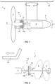
- FIG. 1 shows a marine propeller propulsion unit 1, in the form of an azimuth thruster, and a lowermost potion of a marine vessel 20 to which the thruster is horizontally rotatably connected.
- FIG. 2 shows rearward drive (pushing) a marine propeller propulsion unit 1 comprising a first and a second propeller 2, 3, aka a duoprop, and a portion of a marine vessel 20.
- FIG. 3 shows a unit corresponding to FIG. 2 , but configured as a forwards (pulling) drive.
- the marine propeller propulsion unit 1 comprises a compound planetary gear 10 for driving a single propeller 3.
- the marine propeller propulsion unit 1 comprises a compound planetary gear 10 for driving the first and second propellers 2, 3 by means of an input shaft 4. There may, as illustrated, be one single input shaft 4.
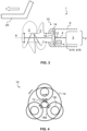
- the compound planetary gear 10 is illustrated in plan view in FIG. 4 .
- the compound planetary gear 10 comprises a sun gear 12, a ring gear 14, a planet carrier 16, a first planet gear 18i and a second planet gear 18e.
- the radius of the second planet gear 18e exceeds the radius of the first planet gear 18i, as is illustrated.
- the first and second planet gears 18i, 18e are rotationally fixed to one another.
- the ring gear 14 meshes with the first, smaller, planet gear 18i and the sun gear 12 meshes with the second, larger, planet gear 18e.
- the sun gear 12 is adapted to be connected to the input shaft 4, the ring gear 14 is adapted to be connected to the first propeller 2, and the planet carrier 16 is adapted to be connected to the second propeller 3.
- the ring gear 14 may be stationary.
- the sun gear 12 may be directly connected to the input shaft 4. Thereby, the sun gear 12 and the input shaft 4 are adapted to rotate at the same velocity. In other words, the sun gear 12 and the input shaft 4 may be rotationally fixed to one another.
- a propulsion motor 5 for driving the input shaft 4.
- the propulsion motor 5 is an electric motor, more precisely one single electric propulsion motor 5 that is directly connected to the input shaft 4 such that the propulsion motor 5 and the input shaft 4 are adapted to rotate at the same velocity.
- the propulsion motor 5 and the input shaft 4 may be rotationally fixed to one another.
- the propulsion motor 5 may be coaxial with the first and second propellers 2, 3, as shown in FIG. 2 and FIG. 3 .
- the input shaft 4 and the first and second propeller shafts, illustrated in FIG. 2 and FIG. 3 may be coaxial. Referring to FIG. 1 , the propulsion motor 5 may be coaxial with the single propeller 3.
- FIG. 1 the propulsion motor 5 may be coaxial with the single propeller 3.
- the first or outer propeller shaft that drives the first propeller 2 may be welded to the ring gear 14.
- the second or inner propeller shaft that drives second propeller 3 may be welded to the planet carrier 16.
- the propeller shaft may be welded to the planet carrier 16.
- the propulsion motor 5 and the compound planetary gear 10 are of approximately the same outer dimension, as shown in FIG. 1 to FIG. 3 and denoted d in FIG. 1 and 3 .
- the radiuses of the sun gear 12 and the first planet gear 18i may be essentially equal.
- the radiuses of the sun gear 12 and the first planet gear 18i may typically differ by up to 20 percent.
- the radius of the second planet gear 18e is approximately 2 times the radius of the first planet gear 18i, a suitable ratio range being approximately 1.5: 1 to 3:1.
- the second planet gear 18e extends radially past the ring gear 14.
- the diameter of the second planet gear 18e plus the radius of the sun gear 12 may exceed the diameter of the ring gear 14.
- the present compound planetary gears comprise three pairs of first and second planet gears 18i, 18e. In other examples, there may be four pairs.
- the compound planetary gear 10 may be oriented with its longitudinal axis A (denoted in FIG. 1 and FIG. 3 ) arranged essentially in plane with the vessel 20 and thus essentially horizontally.
- the compound planetary gear 10 may be oriented with its longitudinal axis A arranged essentially in plane with the vessel 20.
- a brake b 14, b16 or brake assembly is very schematically shown. It is to be apprehended that the example of FIG. 2 may comprise a similar brake.
- the brake may comprise a ring brake b14 that is configured to directly or indirectly brake the ring gear 14 to thereby increase the rotational speed of the planet carrier 16.
- the brake may comprise a carrier brake b16 that is configured to directly or indirectly brake the planet carrier 16 to thereby increase the rotational speed of the ring gear 14.
- breaking the ring gear 14 of a compound planetary gear 10 results in a speed increase of the planet carrier 16, and vice versa.
- the compound planetary gear 10 may comprise helical gears and be configured to cancel out any axial forces generated by the compound planetary gear 10 during operation.
- the helical gears of the sun gear 12 and of the ring gear 14 may have opposite helix hands.
- the podded marine propeller propulsion unit 1 of present FIG. 1 comprises a compound planetary gear 10 for driving a single propeller 3, a propulsion motor 5 for driving the compound planetary gear 10 and a completely submersible housing 6 for enclosing the propulsion motor 5 and the compound planetary gear 10.
- the compound planetary gear 10 comprises a sun gear 12, a ring gear 14, a planet carrier 16, a first planet gear 18i and a second planet gear 18e.
- the radius of the second planet gear 18e may exceed the radius of the first planet gear 18i.
- the first and second planet gears 18i, 18e are rotationally fixed to one another.
- the ring gear 14 meshes with the first planet gear 18i and the sun gear 12 meshes with the second planet gear 18e.
- the sun gear 12 is connected to the propulsion motor 5 and the planet carrier 16 is connected to the propeller 3.
- the ring gear 14 is fixed as regards rotation about the longitudinal axis of the marine propeller propulsion unit.
- FIG. 2 shows the marine propeller propulsion unit 1 configured as a rearward drive propulsion unit, such that the first propeller 2 is a front propeller and the second propeller 3 is a rear propeller.
- FIG. 3 shows the marine propeller propulsion unit 1 configured as a forward drive propulsion unit, such that the first propeller 2 is a rear propeller and the second propeller 3 is a front propeller.
- the marine propeller propulsion units 1 of FIG. 2 and FIG. 3 may be embodied as azimuth thrusters, as is the case in FIG. 1 .
- Relative terms such as “below” or “above” or “upper” or “lower” or “horizontal” or “vertical” may be used herein to describe a relationship of one element to another element as illustrated in the Figures. It will be understood that these terms and those discussed above are intended to encompass different orientations of the device in addition to the orientation depicted in the Figures. It will be understood that when an element is referred to as being “connected” or “coupled” to another element, it can be directly connected or coupled to the other element, or intervening elements may be present. In contrast, when an element is referred to as being “directly connected” or “directly coupled” to another element, there are no intervening elements present.
Landscapes
- Chemical & Material Sciences (AREA)
- Engineering & Computer Science (AREA)
- Combustion & Propulsion (AREA)
- Mechanical Engineering (AREA)
- Ocean & Marine Engineering (AREA)
- Retarders (AREA)
Abstract
Description
- The disclosure relates generally to marine propulsion. In particular aspects, the disclosure relates to a marine propeller propulsion unit comprising a compound planetary gear. The disclosure can be applied to marine vessels, such as water crafts, motorboats, work boats, sport vessels, sailboats, boats, ships, among other vessel types. Although the disclosure may be described with respect to a particular vessel, the disclosure is not restricted to any particular vessel.
- Marine propulsion units are used to propel marine vessels in water. Marine propulsion units mat typically comprise one or more propellers. In some examples, two concentric propellers may be arranged to rotate in opposite directions. The latter solution brings a number of benefits as regards efficiency, maneuverability and acceleration. Although many prior art solutions function satisfactorily, there is still room for improvement in terms of for example efficiency, performance, lifetime and costs.
- According to a first aspect of the present disclosure, there is provided a marine propeller propulsion unit comprising a compound planetary gear for driving a propeller, a propulsion motor for driving the compound planetary gear, and a housing for enclosing the propulsion motor and the compound planetary gear. The compound planetary gear comprises a sun gear, a ring gear, a planet carrier, a first planet gear and a second planet gear, wherein the radius of the second planet gear exceeds the radius of the first planet gear and the first and second planet gears are rotationally fixed to one another. The ring gear meshes with the first planet gear and the sun gear meshes with the second planet gear. The sun gear is adapted to be connected to the propulsion motor and the ring gear is adapted to be connected to the propeller.
- The first aspect of the disclosure may seek to solve the problem of providing an improved marine propeller propulsion unit. Improvements may concern e.g. one or more of energy efficiency, performance, lifetime and costs. The use of a compound planetary gear is advantageous as the high gear ratio that is obtainable allows the propeller to be powered by a high-speed motor. A motor rotating at high speed may generate large power while the size and weight can be kept relatively low. Thereby, the housing may be compact, which is advantageous for reducing appendage drag. Typically, the ring gear is rotationally fixed in relation to the housing. The ring gear may thus be fixed as regards rotation about the longitudinal axis of the marine propeller propulsion unit.
- Optionally in some examples, including in at least one preferred example, the propulsion motor is an electric motor. Apart from environmental benefits resulting from increased efficiency and improved performance as a result of a quick torque response, an electric motor may be particularly compact and positioned next to the compound planetary gear. The electric motor may be positioned in line with the compound planetary gear. Thus, the marine propeller propulsion unit may be compact. The marine propeller propulsion unit may comprise one single propulsion motor.
- Optionally in some examples, including in at least one preferred example, the marine propulsion unit is configured such that the housing at least during operation is completely submerged under water. The marine propulsion unit may form a pod arranged outside a hull of a marine vessel that is driven by the marine propulsion unit. The marine propulsion unit may be referred to as an azimuth thruster. In other words, the housing may be rotated to any horizontal angle with respect to the marine vessel to direct the thrust. The marine propulsion unit may alternatively form a lower part of a marine drive unit that comprises an upper part, which is attached to a marine vessel, and the lower part. The lower part may be rotated horizontally with respect to the upper part to direct the thrust. Technical benefits may include high efficiency and performance, in particular as regards maneuverability.
- Optionally in some examples, including in at least one preferred example, the radiuses of the sun gear and the first planet gear are essentially equal or differ by up to 20 percent. A technical benefit may include an appropriate, and high, gear ratio.
- Optionally in some examples, including in at least one preferred example, the radius of the second planet gear is 1.5 to 3 times the radius of the first planet gear. A technical benefit may include an appropriate, and high, gear ratio.
- Optionally in some examples, including in at least one preferred example, the compound planetary gear is adapted to during operation be arranged with its longitudinal axis arranged essentially in plane with a vessel that comprises, and during operation is propelled by, the marine propeller propulsion unit. A technical benefit may include facilitating arranging the compound planetary gear in a housing that at least during operation be completely submerged under water.
- Optionally in some examples, including in at least one preferred example, the compound planetary gear comprises helical gears. The compound planetary gear may be configured to cancel out any axial forces generated by the compound planetary gear during operation. A technical benefit may include that bearings need to absorb less axial forces, which may lower costs. In addition, helical gears may involve less noise and facilitate a compact design.
- Optionally in some examples, including in at least one preferred example, the marine propeller propulsion unit does not comprise any moving part positioned radially outside the ring gear or the first or second planet gear, apart from the propeller. A technical benefit may include that the housing that encloses the compound planetary gear may be compact, which may be advantageous e.g. for reducing appendage drag. In other words, as seen along the longitudinal axis, all moving parts of the marine propeller propulsion unit, apart from the propeller, may be positioned radially inside the radially outermost of the ring gear, the first planet gear and the second planet gear. The radially outermost of the ring gear, the first planet gear and the second planet gear may form the radially outermost moving part of the compound planetary gear.
- Optionally in some examples, including in at least one preferred example, the sun gear is connected to the propulsion motor, typically a motor shaft thereof, such that the sun gear and the propulsion motor are adapted to rotate at the same velocity. Even though the present disclosure does not exclude a gearing operatively arranged between the sun gear and the propulsion motor to increase or decrease the speed of the sun gear, a technical benefit of the present disclosure may include that no such gearing is required.
- Optionally in some examples, including in at least one preferred example, the compound planetary gear is configured for driving a first and a second propeller. The ring gear may be adapted to be connected to the first propeller, and the planet carrier may be adapted to be connected to the second propeller. First and second coaxial propellers rotating in opposite directions may be advantageous e.g. as regards energy efficiency and performance.
- Optionally in some examples, including in at least one preferred example, the marine propeller propulsion unit may comprise one single input shaft connecting the compound planetary gear and the propulsion motor. A technical benefit may include a compact and cost-effective design.
- Optionally in some examples, including in at least one preferred example, the propulsion motor is directly connected to the input shaft such that the propulsion motor and the input shaft are adapted to rotate at the same velocity. Even though the present disclosure does not exclude a gearing operatively arranged between the propulsion motor and the input shaft to increase or decrease the speed of the input shaft, a technical benefit of the present disclosure may include that no such gearing is required.
- Optionally in some examples, including in at least one preferred example, the marine propeller propulsion unit is configured as a rearward drive propulsion unit, and the first propeller is a front propeller and the second propeller is a rear propeller. Alternatively, the marine propeller propulsion unit may be configured as a forward drive propulsion unit, and the first propeller is a rear propeller and the second propeller is a front propeller.
- According to a second aspect of the disclosure, there is provided a use of a compound planetary gear in a marine propeller propulsion unit for driving a first and, optionally, a second propeller by means of an input shaft. The compound planetary gear comprises a sun gear, a ring gear, a planet carrier, a first planet gear and a second planet gear. The radius of the second planet gear exceeds the radius of the first planet gear and the first and second planet gears are rotationally fixed to one another. The ring gear meshes with the first planet gear and the sun gear meshes with the second planet gear, and the sun gear is adapted to be connected to the input shaft. The ring gear is adapted to be connected to the first propeller. The planet carrier is adapted to be connected to the optional second propeller, while if there is only one (the first) propeller the planet carrier may be rotationally fixed.
- According to a third aspect of the disclosure, there is provided a marine propeller propulsion unit comprising a compound planetary gear for driving a first and a second propeller by means of an input shaft. The compound planetary gear comprises a sun gear, a ring gear, a planet carrier, a first planet gear and a second planet gear, wherein the radius of the second planet gear exceeds the radius of the first planet gear and the first and second planet gears are rotationally fixed to one another. The ring gear meshes with the first planet gear and the sun gear meshes with the second planet gear. The sun gear is adapted to be connected to the input shaft, the ring gear is adapted to be connected to the first propeller, and the planet carrier is adapted to be connected to the second propeller.
- The third aspect of the disclosure may seek to solve the problem of providing an improved marine propeller propulsion unit. Improvements may concern e.g. one or more of energy efficiency, performance, lifetime and costs. The use of a compound planetary gear is advantageous as the high gear ratio that is obtainable allows a propeller to be powered, via the input shaft, by a high-speed motor. A motor, and an input shaft, rotating at high speed may generate and transfer large power while the size and weight can be kept relatively low. Thereby, housings, such as e.g. a drive leg or other housings, which enclose the input shaft and the planetary gear may be compact, which is advantageous for reducing appendage drag. A planetary gear further readily provides for rotating coaxial propellers in opposite directions.
- Optionally in some examples, including in at least one preferred example, the sun gear is directly connected to the input shaft such that the sun gear and the input shaft are adapted to rotate at the same velocity. Even though the present disclosure does not exclude a gearing operatively arranged between the sun gear and the input shaft to increase or decrease the speed of the sun gear, a technical benefit of the present disclosure may include that no such gearing is required.
- Optionally in some examples, including in at least one preferred example, the marine propeller propulsion unit comprises a propulsion motor for driving the input shaft. A technical benefit may include that the propulsion motor may be tailored to the compound planetary gear and to other components of the marine propeller propulsion unit.
- Optionally in some examples, including in at least one preferred example, the marine propeller propulsion unit comprises one single propulsion motor which may be beneficial in view of size, weight and costs.
- Optionally in some examples, including in at least one preferred example, the propulsion motor is directly connected to the input shaft such that the propulsion motor and the input shaft are adapted to rotate at the same velocity. Even though the present disclosure does not exclude a gearing operatively arranged between the propulsion motor and the input shaft to increase or decrease the speed of the input shaft, a technical benefit of the present disclosure may include that no such gearing is required. The propulsion motor may be coaxial with the front and rear propellers, even though the present disclosure does not exclude an angle gear or similar being arranged between the propulsion motor and the propellers. The propulsion motor may be arranged at essentially or exactly the same vertical level as the front and rear propellers during operation.
- Optionally in some examples, including in at least one preferred example, the propulsion motor is coaxial with the first and second propellers. A technical benefit may include facilitating arranging the propulsion motor and the compound planetary gear in one and the same housing. Thus, there may be one single housing that is adapted to contain the propulsion motor and the compound planetary gear, and the propellers may be propelled by shafts extending from the housing. Said housing may at least during operation be completely submerged under water.
- Optionally in some examples, including in at least one preferred example, the propulsion motor and the compound planetary gear are of approximately the same outer dimension. A technical benefit may include reduced appendage drag. The propulsion motor and the compound planetary gear may be of a nearly circular outer shape, and their outer radiuses may be approximately the same or differ by up to 30 percent. A radius difference of up 30 percent may in the present context may be referred to as approximately the same. Optionally in some examples, including in at least one preferred example, the outer dimensions differ by less than 5 percent, less than 10 percent, or less than 20 percent.
- Optionally in some examples, including in at least one preferred example, the input shaft and a first and a second propeller shaft, which connect the respective propeller to the compound planetary gear, are coaxial. A technical benefit may include facilitating arranging the input shaft and the compound planetary gear in one and the same housing. Said housing may at least during operation be completely submerged under water. The propulsion motor may be coaxial with the front and rear propellers, even though the present disclosure does not exclude an angle gear or similar being arranged between the input shaft and the propeller shafts.
- Optionally in some examples, including in at least one preferred example, the second planet gear extends radially past the ring gear. Thus, as compared to other gear of the compound planetary gear, the second planet gear may be comparably large. A technical benefit may include an appropriate, and high, gear ratio. The radius of the second planet gear may be 1.5 to 3 times the radius of the first planet gear and 1.5 to 3 times the radius of the sun gear.
- Optionally in some examples, including in at least one preferred example, the compound planetary gear comprises three of four pairs of first and second planet gears. A greater number of pairs may render the design overly complex and heavy, while a lower number of pairs may not provide sufficient strength and complicate bearing design.
- Optionally in some examples, including in at least one preferred example, the marine propeller propulsion unit comprises a brake that is configured to directly or indirectly brake the ring gear to increase the rotational speed of the planet carrier and/or to directly or indirectly brake the planet carrier to increase the rotational speed of the ring gear. The brake may comprise one or more brake shafts and brake gears, the latter meshing with the ring gear or the planet carrier. A technical benefit may include tailoring the torque distributing or speed of the propellers as desired in various operation modes.
- Optionally in some examples, including in at least one preferred example, the compound planetary gear comprises helical gears. The compound planetary gear may be configured to cancel out any axial forces generated by the compound planetary gear during operation. A technical benefit may include that bearings need to absorb less axial forces, which may lower costs. In addition, helical gears may involve less noise and facilitate a compact design.
- Optionally in some examples, including in at least one preferred example, the marine propeller propulsion unit does not comprise any moving part positioned radially outside the ring gear or the first or second planet gear, apart from the propellers. A technical benefit may include that a housing that encloses the compound planetary gear may be compact, which may be advantageous e.g. for reducing appendage drag.
- The marine propeller propulsion unit may be configured as a rearward drive or a forward drive propulsion unit. In both cases, the high gear ratio and other benefits of the compound planetary gear may be advantageous.
- According to a fourth aspect of the disclosure, there is provided a marine vessel comprising the marine propeller propulsion unit of the first or third aspects. The marine vessel may e.g. be a planing motorboat. The latter may be of a length up to about 60 feet. Typically, such a planing motorboat may have a maximum speed of 25 to 50 knots.
- The disclosed aspects, examples (including any preferred examples), and/or accompanying claims may be suitably combined with each other as would be apparent to anyone of ordinary skill in the art. Additional features and advantages are disclosed in the following description, claims, and drawings, and in part will be readily apparent therefrom to those skilled in the art or recognized by practicing the disclosure as described herein.
- Examples are described in more detail below with reference to the appended drawings.
-
FIG. 1 is an exemplary and schematic view of a podded marine propeller propulsion unit and a portion of a marine vessel according to an example. -
FIG. 2 is an exemplary and schematic view of a rearward drive marine propeller propulsion unit and a stern portion of a marine vessel according to an example. -
FIG. 3 is an exemplary and schematic view of a forward drive marine propeller propulsion unit and a stern portion of a marine vessel according to an example. -
FIG. 4 illustrates a compound planetary gear. - The detailed description set forth below provides information and examples of the disclosed technology with sufficient detail to enable those skilled in the art to practice the disclosure.
- The inventive concept of the present disclosure involves the use of a compound planetary gear, also known as stepped planetary gear or double planet planetary gear, in a marine dual propeller propulsion unit. Technical effects that may be obtained involve high gear ratio and thus high efficiency and compact design.
-
FIG. 1 shows a marinepropeller propulsion unit 1, in the form of an azimuth thruster, and a lowermost potion of amarine vessel 20 to which the thruster is horizontally rotatably connected.FIG. 2 shows rearward drive (pushing) a marinepropeller propulsion unit 1 comprising a first and asecond propeller marine vessel 20.FIG. 3 shows a unit corresponding toFIG. 2 , but configured as a forwards (pulling) drive. InFIG. 1 , the marinepropeller propulsion unit 1 comprises a compoundplanetary gear 10 for driving asingle propeller 3. In bothFIG. 2 andFIG. 3 , the marinepropeller propulsion unit 1 comprises a compoundplanetary gear 10 for driving the first andsecond propellers input shaft 4. There may, as illustrated, be onesingle input shaft 4. - The compound
planetary gear 10 is illustrated in plan view inFIG. 4 . Referring toFIG. 1 to 4 , the compoundplanetary gear 10 comprises asun gear 12, aring gear 14, aplanet carrier 16, afirst planet gear 18i and asecond planet gear 18e. The radius of thesecond planet gear 18e exceeds the radius of thefirst planet gear 18i, as is illustrated. The first andsecond planet gears ring gear 14 meshes with the first, smaller,planet gear 18i and thesun gear 12 meshes with the second, larger,planet gear 18e. Thesun gear 12 is adapted to be connected to theinput shaft 4, thering gear 14 is adapted to be connected to thefirst propeller 2, and theplanet carrier 16 is adapted to be connected to thesecond propeller 3. In the example ofFIG. 1 , only comprising onepropeller 3, thering gear 14 may be stationary. - As is shown in
FIG. 1 to 3 , thesun gear 12 may be directly connected to theinput shaft 4. Thereby, thesun gear 12 and theinput shaft 4 are adapted to rotate at the same velocity. In other words, thesun gear 12 and theinput shaft 4 may be rotationally fixed to one another. - Also illustrated (
FIG. 1 to 3 ) is apropulsion motor 5 for driving theinput shaft 4. In the present examples, thepropulsion motor 5 is an electric motor, more precisely one singleelectric propulsion motor 5 that is directly connected to theinput shaft 4 such that thepropulsion motor 5 and theinput shaft 4 are adapted to rotate at the same velocity. Thus, thepropulsion motor 5 and theinput shaft 4 may be rotationally fixed to one another. Further, thepropulsion motor 5 may be coaxial with the first andsecond propellers FIG. 2 andFIG. 3 . Also, theinput shaft 4 and the first and second propeller shafts, illustrated inFIG. 2 andFIG. 3 , may be coaxial. Referring toFIG. 1 , thepropulsion motor 5 may be coaxial with thesingle propeller 3. In the examplesFIG. 2 andFIG. 3 , the first or outer propeller shaft that drives thefirst propeller 2 may be welded to thering gear 14. The second or inner propeller shaft that drivessecond propeller 3 may be welded to theplanet carrier 16. In the example ofFIG. 1 , the propeller shaft may be welded to theplanet carrier 16. - In the present examples, the
propulsion motor 5 and the compoundplanetary gear 10 are of approximately the same outer dimension, as shown inFIG. 1 to FIG. 3 and denoted d inFIG. 1 and3 . - Referring to
FIG. 1 to 4 , the radiuses of thesun gear 12 and thefirst planet gear 18i may be essentially equal. The radiuses of thesun gear 12 and thefirst planet gear 18i may typically differ by up to 20 percent. - In the illustrated examples, the radius of the
second planet gear 18e is approximately 2 times the radius of thefirst planet gear 18i, a suitable ratio range being approximately 1.5: 1 to 3:1. In the illustrated examples, thesecond planet gear 18e extends radially past thering gear 14. Thus, the diameter of thesecond planet gear 18e plus the radius of thesun gear 12 may exceed the diameter of thering gear 14. - As shown in
FIG. 4 , the present compound planetary gears comprise three pairs of first andsecond planet gears - As is illustrated in
FIG. 1 to FIG. 3 , the compoundplanetary gear 10 may be oriented with its longitudinal axis A (denoted inFIG. 1 andFIG. 3 ) arranged essentially in plane with thevessel 20 and thus essentially horizontally. In other words, during operation, i.e. when thevessel 20 is propelled by the marinepropeller propulsion unit 1, the compoundplanetary gear 10 may be oriented with its longitudinal axis A arranged essentially in plane with thevessel 20. - In
FIG. 3 , abrake b 14, b16 or brake assembly is very schematically shown. It is to be apprehended that the example ofFIG. 2 may comprise a similar brake. The brake may comprise a ring brake b14 that is configured to directly or indirectly brake thering gear 14 to thereby increase the rotational speed of theplanet carrier 16. In addition, or instead, the brake may comprise a carrier brake b16 that is configured to directly or indirectly brake theplanet carrier 16 to thereby increase the rotational speed of thering gear 14. As is known to persons skilled in the art, breaking thering gear 14 of a compoundplanetary gear 10 results in a speed increase of theplanet carrier 16, and vice versa. - Even though not illustrated, the compound
planetary gear 10 may comprise helical gears and be configured to cancel out any axial forces generated by the compoundplanetary gear 10 during operation. To obtain such cancellation, the helical gears of thesun gear 12 and of thering gear 14 may have opposite helix hands. - Referring again to the examples of
FIG. 1 andFIG. 3 , the marinepropeller propulsion unit 1 may, apart from thepropellers ring gear 14 or the first orsecond planet gear FIG. 1 , but also illustrated by the dashed line inFIG. 3 , there may be onesingle housing 6 containing thepropulsion motor 5 and the compoundplanetary gear 10. There may be a similar housing (not shown) in the example ofFIG. 2 . As illustrated inFIG. 1 andFIG. 3 , thehousing 6 may have a radial extension, or diameter, that at least in part is adapted to the radial extension, or diameter, of thepropulsion motor 5 and the compoundplanetary gear 10. For example, there may be a clearance of a few millimeters or a couple of centimeters between thehousing 6 and the radially outer one of thepropulsion motor 5 and the compoundplanetary gear 10. The compoundplanetary gear 10 may comprise no moving part positioned radially outside thering gear 14 or the first orsecond planet gear ring gear 14 and the first orsecond planet gear planetary gear 10. Theentire housing 6 may, at least during operation, be submerged under water. - The podded marine
propeller propulsion unit 1 of presentFIG. 1 comprises a compoundplanetary gear 10 for driving asingle propeller 3, apropulsion motor 5 for driving the compoundplanetary gear 10 and a completelysubmersible housing 6 for enclosing thepropulsion motor 5 and the compoundplanetary gear 10. The compoundplanetary gear 10 comprises asun gear 12, aring gear 14, aplanet carrier 16, afirst planet gear 18i and asecond planet gear 18e. The radius of thesecond planet gear 18e may exceed the radius of thefirst planet gear 18i. The first andsecond planet gears ring gear 14 meshes with thefirst planet gear 18i and thesun gear 12 meshes with thesecond planet gear 18e. Thesun gear 12 is connected to thepropulsion motor 5 and theplanet carrier 16 is connected to thepropeller 3. Thering gear 14 is fixed as regards rotation about the longitudinal axis of the marine propeller propulsion unit. - Again,
FIG. 2 shows the marinepropeller propulsion unit 1 configured as a rearward drive propulsion unit, such that thefirst propeller 2 is a front propeller and thesecond propeller 3 is a rear propeller.FIG. 3 shows the marinepropeller propulsion unit 1 configured as a forward drive propulsion unit, such that thefirst propeller 2 is a rear propeller and thesecond propeller 3 is a front propeller. The marinepropeller propulsion units 1 ofFIG. 2 andFIG. 3 may be embodied as azimuth thrusters, as is the case inFIG. 1 . - Also disclosed are examples according to the following clauses:
- 1. A marine propeller propulsion unit (1) comprising a compound planetary gear (10) for driving a propeller (3), a propulsion motor (5) for driving the compound planetary gear (10), and a housing (6) for enclosing the propulsion motor (5) and the compound planetary gear (10), the compound planetary gear (10) comprising
- a sun gear (12),
- a ring gear (14),
- a planet carrier (16), and
- a first planet gear (18i) and a second planet gear (18e), wherein the radius of the second planet gear (18e) exceeds the radius of the first planet gear (18i) and the first and second planet gears (18i, 18e) are rotationally fixed to one another,
wherein the ring gear (14) meshes with the first planet gear (18i) and the sun gear (12) meshes with the second planet gear (18e), and
- 2. The marine propeller propulsion unit (1) of
clause 1, wherein the propulsion motor (5) is an electric motor. - 3. The marine propeller propulsion unit (1) of
clause - 4. The marine propeller propulsion unit (1) of any preceding clause, wherein the radiuses of the sun gear (12) and the first planet gear (18i) are essentially equal or differ by up to 20 percent.
- 5. The marine propeller propulsion unit (1) of any preceding clause, wherein the radius of the second planet gear (18e) is 1.5 to 3 times the radius of the first planet gear (18i).
- 6. The marine propeller propulsion unit (1) of any preceding clause, wherein the compound planetary gear (10) is adapted to during operation be arranged with its longitudinal axis (A) arranged essentially in plane with a vessel (20) that comprises, and during operation is propelled by, the marine propeller propulsion unit (1).
- 7. The marine propeller propulsion unit (1) of any preceding clause, wherein the compound planetary gear (10) comprises helical gears and is configured to cancel out any axial forces generated by the compound planetary gear (10) during operation.
- 8. The marine propeller propulsion unit (1) of any preceding clause, wherein the marine propeller propulsion unit (1) does not comprise any moving part positioned radially outside the ring gear (14) or the first or second planet gear (18i, 18e), apart from the propeller (2).
- 9. The marine propeller propulsion unit (1) of any preceding clause, wherein the sun gear (12) is connected to the propulsion motor (5) such that the sun gear (12) and the propulsion motor (5) are adapted to rotate at the same velocity.
- 10. The marine propeller propulsion unit (1) of any preceding clause, wherein the compound planetary gear (10) is configured for driving a first and a second propeller (2, 3), wherein the ring gear (14) is adapted to be connected to the first propeller (2), and the planet carrier (16) is adapted to be connected to the second propeller (3).
- 11. The marine propeller propulsion unit (1) of
clause 10, comprising one single input shaft (4) connecting the compound planetary gear (10) and the propulsion motor (5). - 12. The marine propeller propulsion unit (1) of clause 11, wherein the propulsion motor (5) is directly connected to the input shaft (4) such that the propulsion motor (5) and the input shaft (4) are adapted to rotate at the same velocity.
- 13. The marine propeller propulsion unit (1) of any preceding clause, wherein the marine propeller propulsion unit (1) is configured as a rearward drive propulsion unit, and the first propeller (2) is a front propeller and the second propeller (3) is a rear propeller or, wherein the marine propeller propulsion unit (1) is configured as a forward drive propulsion unit, and the first propeller (2) is a rear propeller and the second propeller (3) is a front propeller.
- 14. Use of a compound planetary gear (1) in a marine propeller propulsion unit (1) for driving a first and a second propeller (2, 3) by means of an input shaft (4), wherein the compound planetary gear (10) comprises: a sun gear (12); a ring gear (14); a planet carrier (16); and a first planet gear (18i) and a second planet gear (18e), wherein the radius of the second planet gear (18e) exceeds the radius of the first planet gear (18i) and the first and second planet gears (18i, 18e) are rotationally fixed to one another; wherein the ring gear (14) meshes with the first planet gear (18i) and the sun gear (12) meshes with the second planet gear (18e); and the sun gear (12) is adapted to be connected to the input shaft (4), the ring gear (14) is adapted to be connected to the first propeller (2), and the planet carrier (16) is adapted to be connected to the second propeller (3).
- 15. A marine vessel (20) comprising the marine propeller propulsion unit (1) according to any one of
clauses 1 to 13. - 16. A marine propeller propulsion unit (1) comprising a compound planetary gear (10) for driving a first and a second propeller (2, 3) by means of an input shaft (4), optionally one single input shaft (4), wherein the compound planetary gear (10) comprises a sun gear (12), a ring gear (14), a planet carrier (16), and a first planet gear (18i) and a second planet gear (18e), wherein the radius of the second planet gear (18e) exceeds the radius of the first planet gear (18i) and the first and second planet gears (18i, 18e) are rotationally fixed to one another; wherein the ring gear (14) meshes with the first planet gear (18i) and the sun gear (12) meshes with the second planet gear (18e), and the sun gear (12) is adapted to be connected to the input shaft (4), the ring gear (14) is adapted to be connected to the first propeller (2), and the planet carrier (16) is adapted to be connected to the second propeller (3).
- 17. The marine propeller propulsion unit (1) of
clause 16, wherein the sun gear (12) is directly connected to the input shaft (4) such that the sun gear (12) and the input shaft (4) are adapted to rotate at the same velocity. - 18. The marine propeller propulsion unit (1) of
clause 16 or 17, comprising a propulsion motor (5) for driving the input shaft (4). - 19. The marine propeller propulsion unit (1) of clause 18, wherein the propulsion motor (5) is an electric motor.
- 20. The marine propeller propulsion unit (1) of any preceding clause, wherein the marine propeller propulsion unit (1) comprises one single propulsion motor (5).
- 21. The marine propeller propulsion unit (1) according to any of clauses 18 to 20, wherein the propulsion motor (5) is directly connected to the input shaft (4) such that the propulsion motor (5) and the input shaft (4) are adapted to rotate at the same velocity.
- 22. The marine propeller propulsion unit (1) according to any of clauses 18 to 21, wherein the propulsion motor (5) is coaxial with the first and second propellers (2, 3).
- 23. The marine propeller propulsion unit (1) according clauses 22, wherein the propulsion motor (5) and the compound planetary gear (10) are of approximately the same outer dimension (d).
- 24. The marine propeller propulsion unit (1) according to any of
clauses 16 to 23, wherein the input shaft (4) and a first and a second propeller shaft, which connect the respective propeller (2, 3) to the compound planetary gear (10), are coaxial. - 25. The marine propeller propulsion unit (1) according to any of clauses 22 to 24, comprising a housing (6) that is adapted to contain the compound planetary gear (10) and the propulsion motor (5).
- 26. The marine propeller propulsion unit (1) of clause 25, configured such that the housing (6) is completely submerged under water during operation.
- 27. The marine propeller propulsion unit (1) according to any of
clauses 16 to 26, wherein the radiuses of the sun gear (12) and the first planet gear (18i) are essentially equal or differ by up to 20 percent. - 28. The marine propeller propulsion unit (1) according to any of
clauses 16 to 27, wherein the radius of the second planet gear (18e) is 1.5 to 3 times the radius of the first planet gear (18i). - 29. The marine propeller propulsion unit (1) according to clause 27 or 28, wherein the second planet gear (18e) extends radially past the ring gear (14).
- 30. The marine propeller propulsion unit (1) of any preceding clause, wherein the compound planetary gear (10) comprises three of four pairs of first and second planet gears (18i, 18e).
- 31. The marine propeller propulsion unit (1) according to any of
clauses 16 to 30, wherein the compound planetary gear (10) is adapted to during operation be arranged with its longitudinal axis (A) arranged essentially in plane with a vessel (20) that comprises, and during operation is propelled by, the marine propeller propulsion unit (1). - 32. The marine propeller propulsion unit (1) of any preceding clause, comprising a brake (b14, b16) configured to directly or indirectly brake the ring gear (14) to increase the rotational speed of the planet carrier (16) and/or to directly or indirectly brake the planet carrier (16) to increase the rotational speed of the ring gear (14).
- 33. The marine propeller propulsion unit (1) of any preceding clause, wherein the compound planetary gear (10) comprises helical gears and is configured to cancel out any axial forces generated by the compound planetary gear during operation.
- 34. The marine propeller propulsion unit (1) of clause 33, wherein helical gears of the sun gear (12) and of the ring gear (14) have opposite helix hands.
- 35. The marine propeller propulsion unit (1) according to any of
clauses 16 to 34, wherein the marine propeller propulsion unit (1) does not comprise any moving part positioned radially outside the ring gear (14) or the first or second planet gear (18i, 18e), apart from the propellers (2, 3). - 36. The marine propeller propulsion unit (1) according to any of
clauses 16 to 35, wherein the marine propeller propulsion unit (1) is configured as a rearward drive propulsion unit, and the first propeller (2) is a front propeller and the second propeller (3) is a rear propeller. - 37. The marine propeller propulsion unit (1) according to any of
clauses 16 to 35, wherein the marine propeller propulsion unit (1) is configured as a forward drive propulsion unit, and the first propeller (2) is a rear propeller and the second propeller (3) is a front propeller. - 38. Use of a compound planetary gear (1) in a marine propeller propulsion unit (1) for driving a first and a second propeller (2, 3) by means of an input shaft (4), wherein the compound planetary gear (10) comprises: a sun gear (12); a ring gear (14); a planet carrier (16); and a first planet gear (18i) and a second planet gear (18e), wherein the radius of the second planet gear (18e) exceeds the radius of the first planet gear (18i) and the first and second planet gears (18i, 18e) are rotationally fixed to one another; wherein the ring gear (14) meshes with the first planet gear (18i) and the sun gear (12) meshes with the second planet gear (18e); and the sun gear (12) is adapted to be connected to the input shaft (4), the ring gear (14) is adapted to be connected to the first propeller (2), and the planet carrier (16) is adapted to be connected to the second propeller (3).
- 39. A marine vessel (20) comprising the marine propeller propulsion unit (1) according to any one of
clauses 16 to 37. - 40. The marine vessel (20) of clause 39, wherein the marine vessel (20) is a planing motorboat.
- The terminology used herein is for the purpose of describing particular aspects only and is not intended to be limiting of the disclosure. As used herein, the singular forms "a," "an," and "the" are intended to include the plural forms as well, unless the context clearly indicates otherwise. As used herein, the term "and/or" includes any and all combinations of one or more of the associated listed items. It will be further understood that the terms "comprises," "comprising," "includes," and/or "including" when used herein specify the presence of stated features, integers, actions, steps, operations, elements, and/or components, but do not preclude the presence or addition of one or more other features, integers, actions, steps, operations, elements, components, and/or groups thereof.
- It will be understood that, although the terms first, second, etc., may be used herein to describe various elements, these elements should not be limited by these terms. These terms are only used to distinguish one element from another. For example, a first element could be termed a second element, and, similarly, a second element could be termed a first element without departing from the scope of the present disclosure.
- Relative terms such as "below" or "above" or "upper" or "lower" or "horizontal" or "vertical" may be used herein to describe a relationship of one element to another element as illustrated in the Figures. It will be understood that these terms and those discussed above are intended to encompass different orientations of the device in addition to the orientation depicted in the Figures. It will be understood that when an element is referred to as being "connected" or "coupled" to another element, it can be directly connected or coupled to the other element, or intervening elements may be present. In contrast, when an element is referred to as being "directly connected" or "directly coupled" to another element, there are no intervening elements present.
- Unless otherwise defined, all terms (including technical and scientific terms) used herein have the same meaning as commonly understood by one of ordinary skill in the art to which this disclosure belongs. It will be further understood that terms used herein should be interpreted as having a meaning consistent with their meaning in the context of this specification and the relevant art and will not be interpreted in an idealized or overly formal sense unless expressly so defined herein.
- It is to be understood that the present disclosure is not limited to the aspects described above and illustrated in the drawings; rather, the skilled person will recognize that many changes and modifications may be made within the scope of the present disclosure and appended claims. In the drawings and specification, there have been disclosed aspects for purposes of illustration only and not for purposes of limitation, the scope of the disclosure being set forth in the following claims.
Claims (15)
- A marine propeller propulsion unit (1) comprising a compound planetary gear (10) for driving a propeller (3), a propulsion motor (5) for driving the compound planetary gear (10), and a housing (6) for enclosing the propulsion motor (5) and the compound planetary gear (10), the compound planetary gear (10) comprising- a sun gear (12),- a ring gear (14),- a planet carrier (16), and- a first planet gear (18i) and a second planet gear (18e), wherein the radius of the second planet gear (18e) exceeds the radius of the first planet gear (18i) and the first and second planet gears (18i, 18e) are rotationally fixed to one another,wherein the sun gear (12) is adapted to be connected to the propulsion motor (5) and the ring gear (14) is adapted to be connected to the propeller (3).
wherein the ring gear (14) meshes with the first planet gear (18i) and the sun gear (12) meshes with the second planet gear (18e), and - The marine propeller propulsion unit (1) of claim 1, wherein the propulsion motor (5) is an electric motor.
- The marine propeller propulsion unit (1) of claim 1 or 2, wherein the marine propulsion unit (1) is configured such that the housing (6) at least during operation is completely submerged under water.
- The marine propeller propulsion unit (1) of any preceding claim, wherein the radiuses of the sun gear (12) and the first planet gear (18i) are essentially equal or differ by up to 20 percent.
- The marine propeller propulsion unit (1) of any preceding claim, wherein the radius of the second planet gear (18e) is 1.5 to 3 times the radius of the first planet gear (18i).
- The marine propeller propulsion unit (1) of any preceding claim, wherein the compound planetary gear (10) is adapted to during operation be arranged with its longitudinal axis (A) arranged essentially in plane with a vessel (20) that comprises, and during operation is propelled by, the marine propeller propulsion unit (1).
- The marine propeller propulsion unit (1) of any preceding claim, wherein the compound planetary gear (10) comprises helical gears and is configured to cancel out any axial forces generated by the compound planetary gear (10) during operation.
- The marine propeller propulsion unit (1) of any preceding claim, wherein the marine propeller propulsion unit (1) does not comprise any moving part positioned radially outside the ring gear (14) or the first or second planet gear (18i, 18e), apart from the propeller (3).
- The marine propeller propulsion unit (1) of any preceding claim, wherein the sun gear (12) is connected to the propulsion motor (5) such that the sun gear (12) and the propulsion motor (5) are adapted to rotate at the same velocity.
- The marine propeller propulsion unit (1) of any preceding claim, wherein the compound planetary gear (10) is configured for driving a first and a second propeller (2, 3), wherein the ring gear (14) is adapted to be connected to the first propeller (2), and the planet carrier (16) is adapted to be connected to the second propeller (3).
- The marine propeller propulsion unit (1) of claim 10, comprising one single input shaft (4) connecting the compound planetary gear (10) and the propulsion motor (5).
- The marine propeller propulsion unit (1) of claim 11, wherein the propulsion motor (5) is directly connected to the input shaft (4) such that the propulsion motor (5) and the input shaft (4) are adapted to rotate at the same velocity.
- The marine propeller propulsion unit (1) of any preceding claim, wherein the marine propeller propulsion unit (1) is configured as a rearward drive propulsion unit, and the first propeller (2) is a front propeller and the second propeller (3) is a rear propeller or, wherein the marine propeller propulsion unit (1) is configured as a forward drive propulsion unit, and the first propeller (2) is a rear propeller and the second propeller (3) is a front propeller.
- Use of a compound planetary gear (1) in a marine propeller propulsion unit (1) for driving a first and a second propeller (2, 3) by means of an input shaft (4), wherein the compound planetary gear (10) comprises: a sun gear (12); a ring gear (14); a planet carrier (16); and a first planet gear (18i) and a second planet gear (18e), wherein the radius of the second planet gear (18e) exceeds the radius of the first planet gear (18i) and the first and second planet gears (18i, 18e) are rotationally fixed to one another; wherein the ring gear (14) meshes with the first planet gear (18i) and the sun gear (12) meshes with the second planet gear (18e); and the sun gear (12) is adapted to be connected to the input shaft (4), the ring gear (14) is adapted to be connected to the first propeller (2), and the planet carrier (16) is adapted to be connected to the second propeller (3).
- A marine vessel (20) comprising the marine propeller propulsion unit (1) according to any one of claims 1 to 13.
Priority Applications (2)
| Application Number | Priority Date | Filing Date | Title |
|---|---|---|---|
| EP23218499.4A EP4574646B1 (en) | 2023-12-20 | 2023-12-20 | A marine propulsion unit comprising a compound planetary gear |
| US18/982,151 US20250206426A1 (en) | 2023-12-20 | 2024-12-16 | A marine propulsion unit comprising a compound planetary gear |
Applications Claiming Priority (1)
| Application Number | Priority Date | Filing Date | Title |
|---|---|---|---|
| EP23218499.4A EP4574646B1 (en) | 2023-12-20 | 2023-12-20 | A marine propulsion unit comprising a compound planetary gear |
Publications (2)
| Publication Number | Publication Date |
|---|---|
| EP4574646A1 true EP4574646A1 (en) | 2025-06-25 |
| EP4574646B1 EP4574646B1 (en) | 2026-07-22 |
Family
ID=89224458
Family Applications (1)
| Application Number | Title | Priority Date | Filing Date |
|---|---|---|---|
| EP23218499.4A Active EP4574646B1 (en) | 2023-12-20 | 2023-12-20 | A marine propulsion unit comprising a compound planetary gear |
Country Status (2)
| Country | Link |
|---|---|
| US (1) | US20250206426A1 (en) |
| EP (1) | EP4574646B1 (en) |
Citations (7)
| Publication number | Priority date | Publication date | Assignee | Title |
|---|---|---|---|---|
| GB100013A (en) * | 1915-01-09 | 1916-07-06 | Westinghouse Machine Co | Improvements in or relating to Motor Power Plant. |
| US4963108A (en) * | 1988-11-30 | 1990-10-16 | Mitsubishi Jukogyo Kabushiki Kaisha | Marine contra-rotating propeller drive system |
| US5795200A (en) * | 1994-09-26 | 1998-08-18 | Larkin; Bryan James | Contra-rotating rotor unit |
| CN204056276U (en) * | 2014-08-13 | 2014-12-31 | 北京巴付勒传动技术有限公司 | Boats and ships PODDED PROPULSOR |
| US20150030452A1 (en) * | 2011-06-15 | 2015-01-29 | Samsung Heavy Ind. Co., Ltd. | Propulsion device for ship and ship having the same |
| DE102014005516A1 (en) * | 2014-04-15 | 2015-10-15 | Renk Aktiengesellschaft | Gear arrangement for a ship propulsion and ship propulsion with a gear arrangement |
| US20200140049A1 (en) * | 2016-08-01 | 2020-05-07 | Pure Watercraft, Inc. | Electric marine propulsion systems with drive trains, and associated systems and methods |
-
2023
- 2023-12-20 EP EP23218499.4A patent/EP4574646B1/en active Active
-
2024
- 2024-12-16 US US18/982,151 patent/US20250206426A1/en active Pending
Patent Citations (7)
| Publication number | Priority date | Publication date | Assignee | Title |
|---|---|---|---|---|
| GB100013A (en) * | 1915-01-09 | 1916-07-06 | Westinghouse Machine Co | Improvements in or relating to Motor Power Plant. |
| US4963108A (en) * | 1988-11-30 | 1990-10-16 | Mitsubishi Jukogyo Kabushiki Kaisha | Marine contra-rotating propeller drive system |
| US5795200A (en) * | 1994-09-26 | 1998-08-18 | Larkin; Bryan James | Contra-rotating rotor unit |
| US20150030452A1 (en) * | 2011-06-15 | 2015-01-29 | Samsung Heavy Ind. Co., Ltd. | Propulsion device for ship and ship having the same |
| DE102014005516A1 (en) * | 2014-04-15 | 2015-10-15 | Renk Aktiengesellschaft | Gear arrangement for a ship propulsion and ship propulsion with a gear arrangement |
| CN204056276U (en) * | 2014-08-13 | 2014-12-31 | 北京巴付勒传动技术有限公司 | Boats and ships PODDED PROPULSOR |
| US20200140049A1 (en) * | 2016-08-01 | 2020-05-07 | Pure Watercraft, Inc. | Electric marine propulsion systems with drive trains, and associated systems and methods |
Also Published As
| Publication number | Publication date |
|---|---|
| EP4574646B1 (en) | 2026-07-22 |
| US20250206426A1 (en) | 2025-06-26 |
Similar Documents
| Publication | Publication Date | Title |
|---|---|---|
| US9452815B2 (en) | Contra-rotating propulsor for marine propulsion | |
| US8074592B2 (en) | Submarine with a propulsion drive with an electric motor ring | |
| EP3141472B1 (en) | Podded all-direction pump-jet vector propeller | |
| GB2231546A (en) | "z" type drive for boats has steerable balanced power transmission | |
| US9694887B2 (en) | Propulsion device for ship and ship having the same | |
| JPH1076995A (en) | Propulsion device | |
| CN101678885A (en) | Contra-rotating propeller supported on rudder horn of ship | |
| JPH0417836B2 (en) | ||
| RU2119875C1 (en) | Shipboard propeller-engine plant, type swivel column | |
| KR101261867B1 (en) | Pod type propulsion device and ship with the same | |
| EP3551530B1 (en) | Strut mounted gear box for counter rotating propellers | |
| US20250206426A1 (en) | A marine propulsion unit comprising a compound planetary gear | |
| US5941744A (en) | Vectored propulsion system for sea-going vessels | |
| EP4574641B1 (en) | A marine propulsion unit comprising a double-pinion planetary gear | |
| CN101218148A (en) | Ship power device and ship driving method | |
| CN218986926U (en) | Marine assembled combined type lifting full-rotation power cabin | |
| CN212423430U (en) | Combined type contra-rotating propeller electric propulsion system | |
| NO311337B1 (en) | Boat propulsion unit | |
| SE2351462A1 (en) | A marine propulsion unit comprising a herringbone planetary gear | |
| CN102092467A (en) | Universal propeller | |
| JP3351094B2 (en) | Ship propulsion system using contra-rotating propeller | |
| JPH0615830Y2 (en) | Marine Propeller | |
| CN112407137A (en) | Transmission mechanism for ships and ships | |
| WO2024248638A1 (en) | Maneuvering thruster | |
| JPH01226489A (en) | Submersible propulsion system |
Legal Events
| Date | Code | Title | Description |
|---|---|---|---|
| PUAI | Public reference made under article 153(3) epc to a published international application that has entered the european phase |
Free format text: ORIGINAL CODE: 0009012 |
|
| STAA | Information on the status of an ep patent application or granted ep patent |
Free format text: STATUS: REQUEST FOR EXAMINATION WAS MADE |
|
| 17P | Request for examination filed |
Effective date: 20240924 |
|
| AK | Designated contracting states |
Kind code of ref document: A1 Designated state(s): AL AT BE BG CH CY CZ DE DK EE ES FI FR GB GR HR HU IE IS IT LI LT LU LV MC ME MK MT NL NO PL PT RO RS SE SI SK SM TR |
|
| GRAP | Despatch of communication of intention to grant a patent |
Free format text: ORIGINAL CODE: EPIDOSNIGR1 |
|
| STAA | Information on the status of an ep patent application or granted ep patent |
Free format text: STATUS: GRANT OF PATENT IS INTENDED |
|
| INTG | Intention to grant announced |
Effective date: 20260303 |
|
| GRAS | Grant fee paid |
Free format text: ORIGINAL CODE: EPIDOSNIGR3 |
|
| GRAA | (expected) grant |
Free format text: ORIGINAL CODE: 0009210 |
|
| STAA | Information on the status of an ep patent application or granted ep patent |
Free format text: STATUS: THE PATENT HAS BEEN GRANTED |
|
| AK | Designated contracting states |
Kind code of ref document: B1 Designated state(s): AL AT BE BG CH CY CZ DE DK EE ES FI FR GB GR HR HU IE IS IT LI LT LU LV MC ME MK MT NL NO PL PT RO RS SE SI SK SM TR |
|
| REG | Reference to a national code |
Ref country code: CH Ref legal event code: F10 Free format text: ST27 STATUS EVENT CODE: U-0-0-F10-F00 (AS PROVIDED BY THE NATIONAL OFFICE) Effective date: 20260722 Ref country code: GB Ref legal event code: FG4D |
|
| REG | Reference to a national code |
Ref country code: DE Ref legal event code: R096 Ref document number: 602023020185 Country of ref document: DE |
|
| REG | Reference to a national code |
Ref country code: IE Ref legal event code: FG4D |