EP4574645A1 - Marine propulsion control system - Google Patents
Marine propulsion control system Download PDFInfo
- Publication number
- EP4574645A1 EP4574645A1 EP23219259.1A EP23219259A EP4574645A1 EP 4574645 A1 EP4574645 A1 EP 4574645A1 EP 23219259 A EP23219259 A EP 23219259A EP 4574645 A1 EP4574645 A1 EP 4574645A1
- Authority
- EP
- European Patent Office
- Prior art keywords
- drive unit
- unit
- propellers
- control system
- marine
- Prior art date
- Legal status (The legal status is an assumption and is not a legal conclusion. Google has not performed a legal analysis and makes no representation as to the accuracy of the status listed.)
- Granted
Links
Images




Classifications
-
- B—PERFORMING OPERATIONS; TRANSPORTING
- B63—SHIPS OR OTHER WATERBORNE VESSELS; RELATED EQUIPMENT
- B63H—MARINE PROPULSION OR STEERING
- B63H20/00—Outboard propulsion units, e.g. outboard motors or Z-drives; Arrangements thereof on vessels
- B63H20/08—Means enabling movement of the position of the propulsion element, e.g. for trim, tilt or steering; Control of trim or tilt
- B63H20/12—Means enabling steering
Definitions
- the disclosure relates generally to a propulsion control system.
- the disclosure relates to a marine propulsion control system for a marine vessel.
- the disclosure can be applied to marine vessels, such as water crafts, motorboats, work boats, sport vessels, boats, ships, among other vessel types.
- marine vessels such as water crafts, motorboats, work boats, sport vessels, boats, ships, among other vessel types.
- the disclosure may be described with respect to a particular marine vessel, the disclosure is not restricted to any particular marine vessel.
- Propulsion control systems for marine vessels are known. These propulsions systems having a drive unit which may be operated in different positions so as to improve the marine vessel's performance and energy consumption to power the drive unit. These known systems do not take into account where the marine vessel is operating both in normal draught and in reduced draught situations, as well as in other circumstances and conditions of the marine vessel.
- the drive unit having one or more propellers propelling the marine vessel in normal manner.
- persons and/or equipment are in the water around the marine vessel for bathing and swimming which may have the severe consequence that the person and/or equipment may come in contact with the one or more propellers.
- a marine propulsion control system for a marine vessel comprising a drive unit being adapted to be connected with the marine vessel, the drive unit comprises an upper part being pivotable connected with the marine vessel and a lower part having one or more propellers providing a thrust force, the lower part is rotatable in relation to the upper part, an input unit configured to obtain an activation message indicative of an operation mode for the drive unit, a control unit being operatively connected with the drive unit and the input unit, the control unit is configured to control the drive unit on basis of the activation message obtained from the input unit, wherein the control unit, based on at least the activation message, is configured to control the drive unit within different predetermined operation modes, wherein one of the predetermined operation modes is a swim mode in which the control unit is configured to rotate the lower part of the drive unit so that the one or more propellers is/are facing forward in a position of minimum 90 degrees compared to a rearward facing position of the one or more propellers, wherein the control unit is
- the first aspect of the disclosure may seek to solve the disadvantages with the prior solutions and especially the sometime missing security while operating the marine vessel in different situations.
- a technical benefit may include providing a propulsion control system having a drive unit with a lower part which is rotatably connected with an upper part, whereby the control unit ensures that the one or more propellers are rotated to a position with the one or more propellers at least facing forward in a position of minimum 90 degrees compared to an aft facing position of the one or more propellers when the control unit has obtained a swim mode activation message.
- the risk for damaging persons bathing and swimming around the marine vessel is minimized and a higher security is obtained while operating the marine vessel during swimming and bathing.
- control unit is operatively connected with the tilt and trim arrangement.
- a technical benefit may include that the trim and tilt of the drive unit may be performed and controlled by the control unit.
- the activation message is activated by an operator or captain and/or is an automatically generated activation message.
- a technical benefit may include providing different possibilities for activating the activation message.
- the automatically generated activation message is sensor data obtained from one or more sensor(s).
- a technical benefit may include that the sensors may detect different objects in the surrounding of the marine vessel or other parameters and based on these detections an automatically generated activation message may be provided to the control unit.
- the risk for human failure or unintended operation of the propulsion control system minimized.
- the one or more sensors is/are configured to detect one or more condition(s) of the marine vessel, the drive unit and/or a surrounding of the marine vessel.
- a technical benefit may include that the sensors may detect different conditions of the marine vessel, drive unit and/or surroundings or other parameters and based on these detections an automatically generated activation message may be provided to the control unit for enhanced control and security. Hereby is the risk for human failure or unintended operation of the propulsion control system minimized.
- one of the predetermined operation modes is a normal/high speed mode in which the control unit is configured to control the drive unit, a steering unit, and/or the tilt and trim arrangement so that the trim of the drive unit and steering is set with limitations and no tilt capability of the drive unit.
- a technical benefit may include that it is ensured that the risk for human failure or unintended operation of the propulsion control system minimized.
- the limitation is that the trim of the drive unit cannot exceed ⁇ 10 degrees, preferably ⁇ 5 degrees compared to neutral trim, and that rotation of the lower part of the drive unit is limited to 30 degrees.
- a technical benefit may include that it is ensured that restriction for operating the marine vessel is provided, which again minimizes the risk for human failure or unintended operation of the propulsion control system.
- one of the predetermined operation modes is a slow speed mode in which the control unit is configured to control the drive unit, a steering unit, and/or the tilt and trim arrangement so that the trim of the drive unit is free, unlimited steering up to 360 degrees.
- a technical benefit may that it is ensured that the risk for human failure or unintended operation of the propulsion control system minimized.
- FIGS. 1-3 is an exemplary view of a marine propulsion control system 1 for a marine vessel 100 according to an example.
- the marine propulsion control system 1 comprises a drive unit 3 comprising an upper part 20 and a lower part 21 , the upper part 20 being pivotable in relation to the marine vessel 100 and the lower part 21 is rotatably connected with the upper part 20 .
- the lower part 21 having one or more propellers providing a thrust force.
- the lower part 21 comprises in the present example a first propeller 13a , and a second propeller 13b .
- the upper part 20 of the drive unit 3 may be moved in relation to the transom 101 of the marine vessel 100 so that the drive unit may be tilted in and out of the water and/or trimmed to an intended trim angle in the water. Hence, the upper part 20 may be moved in relation to the marine vessel 100 .
- the lower part 21 is rotatably connected with the upper part 20 whereby the lower part may be rotated in relation to the upper part 20 around an axis R .
- the lower part 21 is configured to follow the movements of the upper part 20 in relation to the marine vessel 100 .
- the marine propulsion control system 1 also comprises an input unit 22 configured to obtain an activation message indicative of an operation mode for the drive unit 3 , and a control unit 23 being operatively connected with the drive unit 3 and the input unit 22 , the control unit 23 is configured to control the drive unit 3 on basis of the activation message obtained from the input unit 22.
- the control unit 23 based on at least the activation message, is configured to control the drive unit 3 within different predetermined operation modes.
- One of the predetermined operation modes is a swim mode in which the control unit 23 is configured to rotate the lower part 21 of the drive unit 3 so that the one or more propellers 13a , 13b is/are facing forward in a position of minimum 90 degrees compared to a rearward facing position of the one or more propellers.
- the control unit 23 is configured to ensure no thrust force and/or rotation of the one or more propellers 13a , 13b in the swim mode.
- the input unit 22 may be arranged at the marine vessel 100 or at the drive unit 3 , in the example in FIG. 1 , the input unit 22 is arranged at the marine vessel 100.
- the control unit may also be arranged at the marine vessel 100 or at the drive unit 3 , in the example in FIG. 1 the input unit 22 is arranged at the marine vessel 100 .
- control unit 23 in response to obtaining a swim mode activation message from the input unit 22 , is configured to rotate the lower part 21 to a position with the one or more propellers 13a , 13b at least facing forward in a position of minimum 90 degrees compared to an aft facing position of the one or more propellers.
- the swim mode activation message may be activated when persons onboard the marine vessel 100 would like to swim around the marine vessel 100 , for instance by using the bathing platform 103 arranged at the transom 101 of the marine vessel 100 .
- the propellers 13a , 13b are configured to be a pushing drive, hence in normal operation they are pushing the marine vessel 100 .
- the first and second propellers 13a , 13b are arranged after the lower part 21 so that when rotated they will push the lower part 21 and thereby push the marine vessel.
- the drive unit 3 may be trimmed in different angles for optimizing the angle of thrust for the propellers 13a , 13b during different operating conditions. In FIG. 1 , the drive unit 3 is positioned in neutral trim where the angle of thrust of the first propeller 13a and the second propeller 13b are zero.
- the drive unit 3 has been pivoted in a clockwise direction in relation to the marine vessel so as to position the drive unit 3 in a negative trim having a negative angle of thrust A of the first propeller 13a and the second propeller 13b .
- the drive unit 3 has been pivoted in an anticlockwise direction in relation to the marine vessel 100 so as to position the drive unit 3 in a positive trim having a positive angle of thrust A of the first propeller 13a and the second propeller 13b .
- FIG. 4 is the marine propulsion control system 1 of FIG. 1 where the lower part 21 has been rotated around the axis R in relation to the upper part 20 .
- the control unit 23 in response to obtaining a swim mode activation message from the input unit 22 , has rotated the lower part 21 to a position with the one or more propellers 13a , 13b facing forward towards the marine vessel 100 .
- the first and second propellers 13a , 13b have been rotated 180 degrees compared to their position shown in FIG. 1 .
- the control unit 23 may rotate the first and second propellers 13a, 13b minimum 90 degrees compared to an aft facing position of the one or more propellers 13a , 13b .
- the control unit 23 may be configured to lower the drive unit 3 to its lowermost position so that the swimmers are further protected from the one or more propellers 13a , 13b.
- the activation message is activated by an operator or captain on the marine vessel 100 and/or is an automatically generated activation message.
- the operator or captain may activate the beach mode activating message at the input unit 22
- the operator or captain may activate the swim mode activating message at the input unit 22 .
- the drive unit 3 may be locked in the swim mode until swim mode activation message is deactivated by the operator or captain.
- the drive unit 3 is configured to be started with a special acknowledgement operation when in swim mode, such as unlocking by a physical or digital key.
- a special acknowledgement operation when in swim mode, such as unlocking by a physical or digital key.
- control unit 23 in response to obtaining a beach mode activation message from the input unit 22 , has rotated the lower part 21 with the one or more propellers 13a , 13b facing aft in relation to the marine vessel 100.
- the drive unit 3 has in the shown example been translated rearward as the same time it has been raised.
- FIG. 9 the drive unit of FIG. 7 is still in the beach mode having the first and second propeller 13a , 13b facing aft.
- the control unit 23 has brought the drive unit 3 to a lower draught than shown in FIG. 8 .
- FIG. 10 is an exemplary view of a propulsion control system 1 for a marine vessel 100 according to an example.
- the propulsion control system 1 comprises a transom bracket 2 configured to be connected with a transom 101 of the marine vessel 100 , and a drive unit 3 .
- the drive unit 3 is arranged to be moved in relation to the transom bracket 2 for moving the drive unit 3 in the water and out of the water.
- the drive unit 3 comprises an upper part 20 and a lower part 21 , the upper part 20 being pivotable in relation to the marine vessel 100 and the lower part 21 is rotatably connected with the upper part 20 , the lower part 21 comprises in the present example a first propeller 13a , and a second propeller 13b .
- the drive unit 3 is connected with the transom bracket 2 via a connecting arm 4 having a first pivot joint 5 connected with the transom bracket 2 and a second pivot joint 6 connected with the drive unit 3 .
- the drive unit 3 is configured to be moved in the water and out of the water by the connecting arm 4 pivots around the first pivot joint 5 or the drive unit 3 pivots around the second pivot joint 6 or the connecting arm 4 and the drive unit 3 pivot around both pivot joints 5 , 6.
- the drive unit 3 may be moved up and down and trimmed.
- the drive unit 3 has been moved rearwards while it has been tilted up by rotating the connecting arm 5 around the first pivot joint 5 .
- the drive unit 3 has been rotated around the second pivot joint 6 of the connecting arm 4 so that a positive trim angle A is obtained of the drive unit 3 .
- the drive unit 3 is configured to be moved by the drive unit is pivoted around the second pivot joint 6 in a clockwise direction or an anticlockwise direction independently of any pivoting of the connecting arm 4 around the first pivot joint 5.
- the drive unit 3 has been pivoted in an anticlockwise direction around the second pivot joint 6 .
- the drive unit 3 is configured to be moved by the connecting arm 4 is pivoted around the first pivot joint 5 in a clockwise direction or an anticlockwise direction at the same time as the drive unit 3 is pivoted around the second pivot joint 6 in a clockwise direction or an anticlockwise direction.
- the connecting arm 4 has pivoted in an anticlockwise direction around the first pivot joint 5 and the drive unit 3 has been pivoted in an anticlockwise direction around the second pivot joint 6 .
- the drive unit 3 may be trimmed in different trim positions by pivoting the drive unit 3 around the second pivot joint 6 and the position in the water of the drive unit may at the same time been obtained by pivoting the connecting arm 4 around the first pivot joint 5 . Freedom to position the drive unit 3 in relation the transom bracket 2 is obtained. Additionally, the drive unit 3 may be moved up and down as well as translated rearwards in relation to the transom bracket 2 while maintaining an improved angle of thrust A .
- the drive unit 3 comprises one or more propellers.
- the drive unit 3 comprises the first propeller 13a and a second propeller 13b .
- the first propeller 13a and the second propeller 13b are configured to push the marine vessel 100 in a forward motion of the marine vessel 100 .
- the one or more propellers are configured to pull the marine vessel 100 in a forward motion of the marine vessel.
- the first propeller 13a and second propeller 13b have an angle of thrust A , indicated by the angle between the dotted line and the arrow in FIG. 10 .
- the drive unit 3 has been pivoted in the anticlockwise direction around the second pivot joint 6 so that a positive trim angle and thereby angle of thrust A for the first propeller 13a and the second propeller 13b.
- the first propeller 13a is arranged to be counter-rotating compared to the second propeller 13b .
- the drive unit 3 may be positioned freely in relation to a transom bracket 2 and thereby the transom 101 of the marine vessel 100 both in rotation but also vertical movements as well as horizontal movements.
- a linear actuator 7 is arranged between the connecting arm 4 and the drive unit 3 .
- the linear actuator 7 is configured to pivot the drive unit 3 around the second pivot joint 6 in either the clockwise direction or the anticlockwise direction and thereby a trim angle of the drive unit 3 and the angle of thrust may be set in relation to the circumstance.
- the linear actuator 7 is connected with the drive unit 3 in a distance below the second pivot joint 6 and is connected with the drive unit 3 via a drive pivot joint 12 so that it is ensured that the linear actuator 7 transfer force to pivot the drive unit 3 around the second pivot joint 6.
- the drive unit 3 has been tilted further up by rotating the connecting arm 4 around the first pivot joint 5 compared to in FIG. 10 .
- the drive unit 3 has been rotated in anticlockwise direction around the second pivot joint 6 of the connecting arm 4 so that an improved angle of thrust A of the first propeller 13a and the second propeller 13b is obtained even though the drive unit 3 has been raised to a positon being higher than a bottom 102 of the marine vessel 100 .
- the drive unit 3 may be trimmed to an optimum position irrespective of the operating in shallow waters since the bottom 102 of the marine vessel 100 is protecting the drive unit 3 and its propellers against impact.
- the connecting arm 4 in FIG. 11 has been pivoted further around the first pivot joint 5 in an anticlockwise direction thereby tilting the drive unit 3 upwards.
- the connecting arm 4 is configured to be pivoted around the first pivot point 5 in maximum 200 degrees, preferably maximum 180 degrees.
- FIG. 21 is another view of an example.
- FIG. 21 shows a marine propulsion control system 1 for a marine vessel 100 , comprising a drive unit 3 being connected with the marine vessel, the drive unit 3 comprises an upper part 20 being pivotable connected with the marine vessel and a lower part 21 having one or more propellers 13a , 13b providing a thrust force, the lower part 21 is rotatable in relation to the upper part 20 , an input unit 22 configured to obtain an activation message indicative of an operation mode for the drive unit 3 , a control unit 23 being operatively connected with the drive unit 3 and the input unit 22 , the control unit 23 is configured to control the drive unit 3 on basis of the activation message obtained from the input unit 22 , wherein the control unit 23 , based on at least the activation message, is configured to control the drive unit 3 within different predetermined operation modes, wherein one of the predetermined operation modes is a swim mode in which the control unit 23 is configured to rotate the lower part 21 of the drive unit 3 so that the one or more propellers 13
- Example 32 The marine propulsion control system ( 1 ) of any of the examples 1-31, wherein the control unit ( 23 ) is configured to issue a notification that it is safe to swim around the drive unit ( 3 ) when the lower part ( 21 ) of the drive unit ( 3 ) has been rotated the position with the one or more propellers ( 13a , 13b) at least facing forward in the position of minimum 90 degrees compared to the aft facing position of the one or more propellers, and the one or more propellers are locked.
- Example 34 The marine propulsion control system ( 1 ) of example 9, wherein the one or more sensor(s) ( 24 ) is/are configured to detect a draught around the marine vessel and based on the detected draught activates the shallow water/beach mode activating message.
- Example 35 The marine propulsion control system ( 1 ) of example 9, wherein the one or more sensor(s) ( 24 , 40 ) is/are configured to detect an obstacle and/or humans or animals around the marine vessel ( 100 ) and based on the detection activates the swim mode activating message.
- Example 36 The marine propulsion control system ( 1 ) of example 9, wherein the one or more sensor(s) ( 24 , 40 ) is/are configured to detect obstacles and/or humans or animals in the vicinity of the one or more propellers ( 13a , 13b).
- Example 37 The marine propulsion control system ( 1 ) of any of the examples 9-36, wherein the one or more sensors ( 24 , 25 , 40 ) are operatively connected with the control unit ( 23 ).
- Example 38 The marine propulsion control system ( 1 ) of any of the examples 9-37, wherein the sensor ( 24 , 25 , 40 ) is a proximity sensor, a LiDAR sensor, a Sonar sensor, a speed log, a torque sensor, a depth sensor, power consumption sensor, a basic on/off switch sensor, a gate sensor, or similar.
- the sensor ( 24 , 25 , 40 ) is a proximity sensor, a LiDAR sensor, a Sonar sensor, a speed log, a torque sensor, a depth sensor, power consumption sensor, a basic on/off switch sensor, a gate sensor, or similar.
- Example 39 The marine propulsion control system ( 1 ) of any of the examples 1-38, wherein the control unit ( 23 ) is configured to issue a notification that the drive unit ( 3 ) is in the shallow water/beach mode when the lower part ( 21 ) of the drive unit ( 3 ) has been rotated the position with the one or more propellers facing aft in relation to the marine vessel, whereby the drive unit can operate the marine vessel in shallow water.
- Example 40 The marine propulsion control system ( 1 ) of any of the examples 1-39, wherein the control unit ( 23 ) is configured is issue one or more indications for indicating when the swim mode is active and thereby it is safe to swim around the drive unit ( 3 ).
- Example 41 The marine propulsion control system ( 1 ) of any of the examples 1-40, wherein at least the swim mode is associated with a green light arranged in connection to a bathing platform of the marine vessel.
- Example 77 The method of any of the examples 68-76, further comprising
Landscapes
- Chemical & Material Sciences (AREA)
- Engineering & Computer Science (AREA)
- Combustion & Propulsion (AREA)
- Mechanical Engineering (AREA)
- Ocean & Marine Engineering (AREA)
- Toys (AREA)
Abstract
Description
- The disclosure relates generally to a propulsion control system. In particular aspects, the disclosure relates to a marine propulsion control system for a marine vessel. The disclosure can be applied to marine vessels, such as water crafts, motorboats, work boats, sport vessels, boats, ships, among other vessel types. Although the disclosure may be described with respect to a particular marine vessel, the disclosure is not restricted to any particular marine vessel.
- Propulsion control systems for marine vessels are known. These propulsions systems having a drive unit which may be operated in different positions so as to improve the marine vessel's performance and energy consumption to power the drive unit. These known systems do not take into account where the marine vessel is operating both in normal draught and in reduced draught situations, as well as in other circumstances and conditions of the marine vessel.
- The drive unit having one or more propellers propelling the marine vessel in normal manner. However, sometimes persons and/or equipment are in the water around the marine vessel for bathing and swimming which may have the severe consequence that the person and/or equipment may come in contact with the one or more propellers.
- Hence, there is a need for an improved marine propulsion control system with enhanced security during different operation modes.
- According to a first aspect of the disclosure, a marine propulsion control system for a marine vessel, comprising a drive unit being adapted to be connected with the marine vessel, the drive unit comprises an upper part being pivotable connected with the marine vessel and a lower part having one or more propellers providing a thrust force, the lower part is rotatable in relation to the upper part, an input unit configured to obtain an activation message indicative of an operation mode for the drive unit, a control unit being operatively connected with the drive unit and the input unit, the control unit is configured to control the drive unit on basis of the activation message obtained from the input unit, wherein the control unit, based on at least the activation message, is configured to control the drive unit within different predetermined operation modes, wherein one of the predetermined operation modes is a swim mode in which the control unit is configured to rotate the lower part of the drive unit so that the one or more propellers is/are facing forward in a position of minimum 90 degrees compared to a rearward facing position of the one or more propellers, wherein the control unit is configured to ensure no thrust force and/or rotation of the one or more propellers in the swim mode. The first aspect of the disclosure may seek to solve the disadvantages with the prior solutions and especially the sometime missing security while operating the marine vessel in different situations. A technical benefit may include providing a propulsion control system having a drive unit with a lower part which is rotatably connected with an upper part, whereby the control unit ensures that the one or more propellers are rotated to a position with the one or more propellers at least facing forward in a position of minimum 90 degrees compared to an aft facing position of the one or more propellers when the control unit has obtained a swim mode activation message. Hereby the risk for damaging persons bathing and swimming around the marine vessel is minimized and a higher security is obtained while operating the marine vessel during swimming and bathing.
- Optionally in some examples, including in at least one preferred example, further comprising a tilt and trim arrangement, the control unit is operatively connected with the tilt and trim arrangement. A technical benefit may include that the trim and tilt of the drive unit may be performed and controlled by the control unit.
- Optionally in some examples, including in at least one preferred example, the activation message is activated by an operator or captain and/or is an automatically generated activation message. A technical benefit may include providing different possibilities for activating the activation message.
- Optionally in some examples, including in at least one preferred example, the automatically generated activation message is sensor data obtained from one or more sensor(s). A technical benefit may include that the sensors may detect different objects in the surrounding of the marine vessel or other parameters and based on these detections an automatically generated activation message may be provided to the control unit. Hereby is the risk for human failure or unintended operation of the propulsion control system minimized.
- Optionally in some examples, including in at least one preferred example, further comprising one or more sensor(s), the one or more sensors is/are configured to detect one or more condition(s) of the marine vessel, the drive unit and/or a surrounding of the marine vessel. A technical benefit may include that the sensors may detect different conditions of the marine vessel, drive unit and/or surroundings or other parameters and based on these detections an automatically generated activation message may be provided to the control unit for enhanced control and security. Hereby is the risk for human failure or unintended operation of the propulsion control system minimized.
- Optionally in some examples, including in at least one preferred example, one of the predetermined operation modes is a normal/high speed mode in which the control unit is configured to control the drive unit, a steering unit, and/or the tilt and trim arrangement so that the trim of the drive unit and steering is set with limitations and no tilt capability of the drive unit. A technical benefit may include that it is ensured that the risk for human failure or unintended operation of the propulsion control system minimized.
- Optionally in some examples, including in at least one preferred example, the limitation is that the trim of the drive unit cannot exceed ± 10 degrees, preferably ±5 degrees compared to neutral trim, and that rotation of the lower part of the drive unit is limited to 30 degrees. A technical benefit may include that it is ensured that restriction for operating the marine vessel is provided, which again minimizes the risk for human failure or unintended operation of the propulsion control system.
- Optionally in some examples, including in at least one preferred example, one of the predetermined operation modes is a slow speed mode in which the control unit is configured to control the drive unit, a steering unit, and/or the tilt and trim arrangement so that the trim of the drive unit is free, unlimited steering up to 360 degrees. A technical benefit may that it is ensured that the risk for human failure or unintended operation of the propulsion control system minimized.
- Optionally in some examples, including in at least one preferred example, further comprising an additional drive unit arranged adjacent to the other drive unit whereby a twin drive unit installation is obtained. A technical benefit may include that more power and maneuverability to the propulsion system is provided and that a redundant system is obtained.
- Optionally in some examples, including in at least one preferred example, the control unit, in the slow speed mode, is configured to rotate the lower parts of drive units in opposite directions so that collisions between the lower parts are avoided. A technical benefit may include that the drive units and the propellers not unintendedly are rotated to collide with each other and thereby that they are being damaged.
- Optionally in some examples, including in at least one preferred example, one of the predetermined operation modes is shallow water/beach mode in which the control unit is configured to control the drive unit, a steering unit, and/or the tilt and trim arrangement so that the trim and tilt is free, unlimited steering up to 360 degrees, preferably ±120 degrees. A technical benefit may include that it is ensured that the risk for human failure or unintended operation of the propulsion control system minimized.
- Optionally in some examples, including in at least one preferred example, the control unit is configured to rotate the lower part to a position with the one or more propellers facing aft in relation to the marine vessel. A technical benefit may include that the risk for damaging the one or more propellers when operating in shallow waters and at the beach is minimized
Optionally in some examples, including in at least one preferred example, the control unit is configured to limit the thrust force of the propellers so that a limited speed only is allowed in the shallow water/beach mode. A technical benefit may include that it is ensured that the risk for human failure or unintended operation of the propulsion control system minimized during operation is shallow waters where there is a high risk for colliding with obstacles under water. - Optionally in some examples, including in at least one preferred example, one of the predetermined operation modes is a storage mode in which the control unit is configured to control the drive unit, a steering unit, and/or the tilt and trim arrangement so that the drive unit is trimmed and tilted out of water, and the control unit is configured to ensure no thrust force and/or rotation of the one or more propeller. A technical benefit may include that it is ensured that the risk for human failure or unintended operation of the propulsion control system minimized.
- Optionally in some examples, including in at least one preferred example, the control unit is configured to rotate the lower part to a position with the one or more propellers facing aft in relation to the marine vessel, in the storage mode. A technical benefit may include that the propeller(s) is/are tilted up of the water so that growth and fouling on the propellers are minimized in the storage mode.
- According to a second aspect of the disclosure, a marine vessel comprising a marine propulsion control system as described above. The second aspect of the disclosure may seek to solve the disadvantages with the prior solutions and especially the sometime missing security while operating the marine vessel in different situations. A technical benefit may include providing a propulsion control system having a drive unit with a lower part which is rotatably connected with an upper part, whereby the control unit ensures that the one or more propellers are rotated to a position with the one or more propellers at least facing forward in a position of minimum 90 degrees compared to an aft facing position of the one or more propellers when the control unit has obtained a swim mode activation message. Hereby the risk for damaging persons bathing and swimming around the marine vessel is minimized and a higher security is obtained while operating the marine vessel during swimming and bathing.
- According to a third aspect of the disclosure, a method of operating a marine propulsion control system as described above, comprising
- providing a marine propulsion control system as described above, on a marine vessel,
- obtaining an activation message indicative of a predetermined operation mode for the drive unit,
- controlling the drive unit on basis of the activation message,
- obtaining swim mode activation message,
- rotating, in response to obtaining swim mode activation message, the lower part of the drive unit so that the one or more propellers is/are facing forward in a position of minimum 90 degrees compared to a rearward facing position of the one or more propellers,
- ensuring that no thrust force and/or rotation of the one or more propellers in the swim mode. The third aspect of the disclosure may seek to solve the disadvantages with the prior solutions and especially the sometime missing security while operating the marine vessel in different situations. A technical benefit may include providing a propulsion control system having a drive unit with a lower part which is rotatably connected with an upper part, whereby the control unit ensures that the one or more propellers are rotated to a position with the one or more propellers at least facing forward in a position of minimum 90 degrees compared to an aft facing position of the one or more propellers when the control unit has obtained a swim mode activation message. Hereby the risk for damaging persons bathing and swimming around the marine vessel is minimized and a higher security is obtained while operating the marine vessel during swimming and bathing.
- Optionally in some examples, including in at least one preferred example, further comprising
- obtaining a normal/high speed mode activation massage,
- setting, in response to obtaining normal/high speed mode activation message, limitations to the trim of the drive unit and steering, and
- setting no tilt capability of the drive unit. A technical benefit may include that it is ensured that the risk for human failure or unintended operation of the propulsion control system minimized.
- The disclosed aspects, examples (including any preferred examples), and/or accompanying claims may be suitably combined with each other as would be apparent to anyone of ordinary skill in the art. Additional features and advantages are disclosed in the following description, claims, and drawings, and in part will be readily apparent therefrom to those skilled in the art or recognized by practicing the disclosure as described herein.
- Examples are described in more detail below with reference to the appended drawings.
-
FIGS. 1-3 is an exemplary a marine propulsion control system according to an example. -
FIG. 4 shows in a side view a marine propulsion control system where the one or more propellers have been rotated to facing forward. -
FIG. 5 shows in a top view a drive unit -
FIGS. 6a-6g show in a top view a sequence of rotating a lower part of the drive unit according to an example. -
FIGS. 7-9 shows a marine propulsion control system according to an example. -
FIGS 10-11 show in a side view the drive unit being translated rearwards according to an example. -
FIGS. 12-15 show different view of an example of a connecting arm according to an example. -
FIGS. 16-17 show different view of another example of a connecting arm according to an example. -
FIGS. 18-19 show different view of another example of a connecting arm according to an example. -
FIG. 20 shows a view of another example of a connecting arm according to an example. -
FIG. 21 is another view of an example. -
FIGS. 22-24 show a marine vessel in a side view with a marine propulsion control system according to an example. -
FIGS. 25-26 show a marine vessel in a side view with a marine propulsion control system according to another example. -
FIG. 27 shows an example of the marine propulsion control system. -
FIG. 28 shows another view of an exemplary of the marine propulsion control system. -
FIG. 29 is a schematic flowchart of an example of a method operating a marine propulsion control system. - The detailed description set forth below provides information and examples of the disclosed technology with sufficient detail to enable those skilled in the art to practice the disclosure.
-
FIGS. 1-3 is an exemplary view of a marinepropulsion control system 1 for amarine vessel 100 according to an example. InFIG. 1 , the marinepropulsion control system 1 comprises adrive unit 3 comprising anupper part 20 and alower part 21, theupper part 20 being pivotable in relation to themarine vessel 100 and thelower part 21 is rotatably connected with theupper part 20. Thelower part 21 having one or more propellers providing a thrust force. Thelower part 21 comprises in the present example afirst propeller 13a, and asecond propeller 13b. Theupper part 20 of thedrive unit 3 may be moved in relation to thetransom 101 of themarine vessel 100 so that the drive unit may be tilted in and out of the water and/or trimmed to an intended trim angle in the water. Hence, theupper part 20 may be moved in relation to themarine vessel 100. Thelower part 21 is rotatably connected with theupper part 20 whereby the lower part may be rotated in relation to theupper part 20 around an axis R. Thelower part 21 is configured to follow the movements of theupper part 20 in relation to themarine vessel 100. - The marine
propulsion control system 1 also comprises aninput unit 22 configured to obtain an activation message indicative of an operation mode for thedrive unit 3, and acontrol unit 23 being operatively connected with thedrive unit 3 and theinput unit 22, thecontrol unit 23 is configured to control thedrive unit 3 on basis of the activation message obtained from theinput unit 22. Thecontrol unit 23, based on at least the activation message, is configured to control thedrive unit 3 within different predetermined operation modes. One of the predetermined operation modes is a swim mode in which thecontrol unit 23 is configured to rotate thelower part 21 of thedrive unit 3 so that the one ormore propellers control unit 23 is configured to ensure no thrust force and/or rotation of the one ormore propellers - The
input unit 22 may be arranged at themarine vessel 100 or at thedrive unit 3, in the example inFIG. 1 , theinput unit 22 is arranged at themarine vessel 100. The control unit may also be arranged at themarine vessel 100 or at thedrive unit 3, in the example inFIG. 1 theinput unit 22 is arranged at themarine vessel 100. - According to the disclosure, the
control unit 23, in response to obtaining a swim mode activation message from theinput unit 22, is configured to rotate thelower part 21 to a position with the one ormore propellers marine vessel 100 would like to swim around themarine vessel 100, for instance by using thebathing platform 103 arranged at thetransom 101 of themarine vessel 100. - In
FIGS. 1-3 , thepropellers marine vessel 100. In the example, the first andsecond propellers lower part 21 so that when rotated they will push thelower part 21 and thereby push the marine vessel. - The
drive unit 3 may be trimmed in different angles for optimizing the angle of thrust for thepropellers FIG. 1 , thedrive unit 3 is positioned in neutral trim where the angle of thrust of thefirst propeller 13a and thesecond propeller 13b are zero. - In
FIG. 2 , thedrive unit 3 has been pivoted in a clockwise direction in relation to the marine vessel so as to position thedrive unit 3 in a negative trim having a negative angle of thrust A of thefirst propeller 13a and thesecond propeller 13b. - In
FIG. 3 , thedrive unit 3 has been pivoted in an anticlockwise direction in relation to themarine vessel 100 so as to position thedrive unit 3 in a positive trim having a positive angle of thrust A of thefirst propeller 13a and thesecond propeller 13b. -
FIG. 4 is the marinepropulsion control system 1 ofFIG. 1 where thelower part 21 has been rotated around the axis R in relation to theupper part 20. Thecontrol unit 23, in response to obtaining a swim mode activation message from theinput unit 22, has rotated thelower part 21 to a position with the one ormore propellers marine vessel 100. In the example, the first andsecond propellers FIG. 1 . According to the disclosure, thecontrol unit 23 may rotate the first andsecond propellers more propellers control unit 23 may be configured to lower thedrive unit 3 to its lowermost position so that the swimmers are further protected from the one ormore propellers - In an example, the activation message is activated by an operator or captain on the
marine vessel 100 and/or is an automatically generated activation message. The operator or captain may activate the beach mode activating message at theinput unit 22, and/or the operator or captain may activate the swim mode activating message at theinput unit 22. - Moreover, the
drive unit 3 may be locked in the swim mode until swim mode activation message is deactivated by the operator or captain. In an example, thedrive unit 3 is configured to be started with a special acknowledgement operation when in swim mode, such as unlocking by a physical or digital key. Hereby an additional security is added to thesystem 1 so that thedrive unit 3 is not operated unintendedly when swimmers are near thedrive unit 3. - In addition, the one or
more propellers lower part 21 is rotated to its intended position before the one ormore propellers - The
drive unit 3 may also comprise one ormore unit sensors 25 configured to detect a position of thelower part 21 of thedrive unit 3 and/or the position of the one ormore propellers more unit sensors 25 may be configured to detect a height position of thedrive unit 3. Furthermore, the one ormore unit sensors 25 are operatively connected with thecontrol unit 23. Hence, thecontrol unit 23 is configured to control thedrive unit 3 with the additional assistance of the detection of the one ormore unit sensors 25. - In
FIG. 5 , thepropulsion control system 1 ofFIG. 1 is shown in a top view. The first andsecond propellers FIG. 1 . The automatically generated activation message may also be based on sensor data obtained from one or more sensor(s) 24. Moreover, the one or more sensor(s) may be configured to detect one or more condition(s) of the marine vessel, the drive unit and/or a surrounding of the marine vessel. Thecontrol unit 23 is operatively connected with the one ormore sensors 24. - The one or more conditions of the
marine vessel 100 may be load on the marine vessel, movement of the marine vessel, trim of the marine vessel, components on the marine vessel, position of a bathing platform, position of a bathing ladder, and others. - The one or more conditions of the
drive unit 3 may be a position of the one or more propellers (steering angle), rpm of the propellers, trim angles, tilt angles, torque, consumption, position of the lower part compared to the upper part, height position, and others. - The surroundings may be detection of persons and/or objects around the marine vessel, depth, waves, and others.
- According to an example, the
control unit 23 may be configured to automatically set thedrive unit 3 in a predetermined operation mode based on the detected conditions and/or surroundings. The sensor may be a speed log, torque sensor, a depth sensor, proximity sensor, positioning unit, movement sensor, gate sensor, etc. - The one or more sensor(s) 24 may for instance be configured to detect a draught around the
marine vessel 100 and based on the detected draught activates the shallow water/beach mode activating message. In another example, the one or more sensor(s) 24 may be configured to detect an obstacle and/or humans or animals around themarine vessel 100 and based on the detection activates the swim mode activating message. The one or more sensor(s) 24 may also be configured to detect obstacles and/or humans or animals in the vicinity of the one ormore propellers more sensors 24 are operatively connected with thecontrol unit 23. - The one or
more sensors 24 may be arranged on the vessel and/or on thedrive unit 3. Thesensor 24 may be a proximity sensor, LiDAR sensor, a Sonar sensor, a speed log, a torque sensor, and/or a depth sensor. The one ormore sensors 24 may be a basic on/off switch, sensing or detecting if a gate to the bathing platform is opened or closed, or other mechanical parts. The one ormore sensors 24 is/are configured to provide thecontrol unit 23 with feedback to what mode thecontrol unit 23 is allowed to activate. - Moreover, the
control unit 23 may be configured to issue one or more indications for indicating when the swim mode is active and thereby it is safe to swim around thedrive unit 3. At least the swim mode may be associated with a green light orindication 30 arranged in connection to abathing platform 103 of themarine vessel 100 so that it is visible for the swimmers in the water and/or onboard themarine vessel 100 that it is safe to swim around the marine vessel. - The
control unit 23 is also configured to issue a notification that it is safe to swim around thedrive unit 3 when thelower part 21 of thedrive unit 3 has been rotated the position with the one ormore propellers more propellers more propellers - In addition,
LiDAR vessel sensors 40 or other proximity sensors configured to detect obstacles and/or humans, may be arranged around themarine vessel 100 for detecting obstacles and/or humans around themarine vessel 100. InFIG. 5 , theLiDAR vessel sensors 40 are arranged in each corner of themarine vessel 100. TheLiDAR vessel sensors 40 are operatively connected with thecontrol unit 23 so that thecontrol unit 23 is configured to control thedrive unit 3 with the additional assistance of the detection of theLiDAR vessel sensors 40. Thecontrol unit 23 may also be configured to process the detected obstacles and/or humans and to present the detected obstacles and/or humans on a display for the operator or captain so that the captain is presented with real-time data about the objects around thedrive unit 3. - The
drive unit 3 may be an outboard motor. The motor may be an electric motor. - In
FIGS. 6a-6g , an example of rotating thelower part 21 is shown as a sequence. The sequence is shown in a top view and is based on the drive unit shown inFIG. 5 . As an example, the position of thelower part 21 where the first andsecond propellers FIG. 6a , thelower part 21 has been rotated in a clockwise direction to a position 45 degrees compared to the position ofFIG. 5 . InFIG. 6b , thelower part 21 has been rotated in the clockwise direction to a position 90 degrees compared to the position ofFIG. 5 . In this position, thedrive unit 3 is in the swim mode position. InFIG. 6c , thelower part 21 has been rotated further in the clockwise direction to a position 135 degrees compared to the position ofFIG. 5 . In this position, thedrive unit 3 is in the swim mode position. InFIG. 6d , thelower part 21 has been rotated further in the clockwise direction to a position 180 degrees compared to the position ofFIG. 5 . It is the same position as shown inFIG. 4 and thedrive unit 3 is in the swim mode position. InFIG. 6e , thelower part 21 has been rotated further in the clockwise direction to a position 225 degrees compared to the position ofFIG. 5 . In this position, thedrive unit 3 is in the swim mode position. InFIG. 6f , thelower part 21 has been rotated further in the clockwise direction to a position 270 degrees compared to the position ofFIG. 5 . In this position, thedrive unit 3 is in the swim mode position. InFIG. 6g , thelower part 21 has been rotated further in the clockwise direction to a position 315 degrees compared to the position ofFIG. 5 . - In the example, the
lower part 21 has been rotated in the clockwise direction. In another example, it may be rotated in an anti-clockwise direction or it may be rotated in both directions. - The
lower part 21 may be rotatably connected with theupper part 20 over 360 degrees. - In
FIGS. 7-9 , thepropellers marine vessel 100. In the example, the first andsecond propellers lower part 21 so that when rotated they will pull thelower part 21 as seen in the example inFIG. 7 . Since, the first andsecond propellers marine vessel 100, they are being locked in a position with the one ormore propellers more propellers control unit 23 obtains a swim mode activation message from theinput unit 22. In addition, thecontrol unit 23 may bring thedrive unit 3 to a maximum draught position. Thelower part 21 rotate around the axis R. - In
FIG. 8 , thecontrol unit 23, in response to obtaining a beach mode activation message from theinput unit 22, has rotated thelower part 21 with the one ormore propellers marine vessel 100. Thedrive unit 3 has in the shown example been translated rearward as the same time it has been raised. - In
FIG. 9 , the drive unit ofFIG. 7 is still in the beach mode having the first andsecond propeller FIG. 9 thecontrol unit 23 has brought thedrive unit 3 to a lower draught than shown inFIG. 8 . - In addition, one of the predetermined operation modes may be a normal/high speed mode. The
control unit 23 is configured to control thedrive unit 3, a steering unit, and/or the tilt and trim arrangement so that the trim of thedrive unit 3 and steering is set with limitations and no tilt capability of thedrive unit 3. When thedrive unit 3 is unable to be tilted it cannot be lifted out of the water. The limitation of the trim of thedrive unit 3 may be set to that the trim cannot exceed ±10 degrees, preferably ±5 degrees compared to neutral trim, and that rotation of thelower part 21 of thedrive unit 3 may be limited to 30 degrees. Hereby is ensured that the driver cannot maneuver the marine vessel unintendedly. - Furthermore, one of the predetermined operation modes may be a slow speed mode in which the
control unit 23 is configured to control thedrive unit 3, a steering unit, and/or the tilt and trim arrangement so that the trim of thedrive unit 3 is free, unlimited steering up to 360 degrees in a single drive unit installation. An additional drive unit may be arranged adjacent to the other drive unit whereby a twin drive unit installation is obtained. Thecontrol unit 23, in the slow speed mode, may be configured to rotate thelower parts 21 ofdrive units 3 in opposite directions so that collisions between the lower parts are avoided. This is further described in relation toFIG. 27 . Also, thecontrol unit 23, in the slow speed mode, may be configured to allow rotation of the lower parts of ±90 degrees. - Moreover, one of the predetermined operation modes is shallow water/beach mode in which the
control unit 23 is configured to control thedrive unit 3, a steering unit, and/or the tilt and trim arrangement so that the trim and tilt is free, unlimited steering up to 360 degrees, preferably ±120 degrees. - The
control unit 23, in response to obtaining a shallow water/beach mode activation message from theinput unit 22, may be configured to bring the drive unit to a reduced draught mode of operation. Hence, thedrive unit 3 may be moved upwards to the reduced draught position when thecontrol unit 23 obtains the shallow water/beach mode activation message. - Furthermore, the
control unit 23 may be configured to issue a notification that thedrive unit 3 is in the shallow water/beach mode when thelower part 21 of thedrive unit 3 has been rotated the position with the one ormore propellers marine vessel 100, whereby thedrive unit 3 can run the marine vessel in shallow water. Thecontrol unit 23 may be configured to limit the thrust force of the propellers so that a limited speed only is allowed in the shallow water/beach mode. - Additionally, one of the predetermined operation modes may be a storage mode in which the
control unit 23 is configured to control the drive unit, a steering unit, and/or the tilt and trim arrangement so that thedrive unit 3 is trimmed and tilted out of water, and thecontrol unit 23 is configured to ensure no thrust force and/or rotation of the one or more propellers. By ensuring that the propellers cannot turn or rotated enhanced security is obtained. Thecontrol unit 23 may also be configured to rotate thelower part 21 to a position with the one ormore propellers control unit 23, in the storage mode, may be configured to limit rotation of the lower part to ± 30 degrees, preferably zero degrees, so that the propellers may be positioned with an angle, if so desired. -
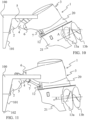
FIG. 10 is an exemplary view of apropulsion control system 1 for amarine vessel 100 according to an example. Thepropulsion control system 1 comprises atransom bracket 2 configured to be connected with atransom 101 of themarine vessel 100, and adrive unit 3. Thedrive unit 3 is arranged to be moved in relation to thetransom bracket 2 for moving thedrive unit 3 in the water and out of the water. Thedrive unit 3 comprises anupper part 20 and alower part 21, theupper part 20 being pivotable in relation to themarine vessel 100 and thelower part 21 is rotatably connected with theupper part 20, thelower part 21 comprises in the present example afirst propeller 13a, and asecond propeller 13b. Thedrive unit 3 is connected with thetransom bracket 2 via a connectingarm 4 having a first pivot joint 5 connected with thetransom bracket 2 and a second pivot joint 6 connected with thedrive unit 3. Thedrive unit 3 is configured to be moved in the water and out of the water by the connectingarm 4 pivots around the first pivot joint 5 or thedrive unit 3 pivots around the second pivot joint 6 or the connectingarm 4 and thedrive unit 3 pivot around bothpivot joints drive unit 3 may be moved up and down and trimmed. - In
FIG. 10 , thedrive unit 3 has been moved rearwards while it has been tilted up by rotating the connectingarm 5 around thefirst pivot joint 5. In addition, thedrive unit 3 has been rotated around thesecond pivot joint 6 of the connectingarm 4 so that a positive trim angle A is obtained of thedrive unit 3. - The
drive unit 3 is configured to be moved by the connectingarm 4 is pivoted around the first pivot joint 5 in a clockwise direction or an anticlockwise direction independently of any pivoting of the drive unit around thesecond pivot joint 6. InFIG. 10 , the connectingarm 4 has been pivoted in an anticlockwise direction around thefirst pivot joint 5. - In addition, the
drive unit 3 is configured to be moved by the drive unit is pivoted around the second pivot joint 6 in a clockwise direction or an anticlockwise direction independently of any pivoting of the connectingarm 4 around thefirst pivot joint 5. InFIG. 10 , thedrive unit 3 has been pivoted in an anticlockwise direction around thesecond pivot joint 6. - The
drive unit 3 is configured to be moved by the connectingarm 4 is pivoted around the first pivot joint 5 in a clockwise direction or an anticlockwise direction at the same time as thedrive unit 3 is pivoted around the second pivot joint 6 in a clockwise direction or an anticlockwise direction. InFIG. 10 , the connectingarm 4 has pivoted in an anticlockwise direction around thefirst pivot joint 5 and thedrive unit 3 has been pivoted in an anticlockwise direction around thesecond pivot joint 6. Hence, thedrive unit 3 may be trimmed in different trim positions by pivoting thedrive unit 3 around thesecond pivot joint 6 and the position in the water of the drive unit may at the same time been obtained by pivoting the connectingarm 4 around thefirst pivot joint 5. Freedom to position thedrive unit 3 in relation thetransom bracket 2 is obtained. Additionally, thedrive unit 3 may be moved up and down as well as translated rearwards in relation to thetransom bracket 2 while maintaining an improved angle of thrust A. - In an example, the
drive unit 3 comprises one or more propellers. InFIG. 10 , thedrive unit 3 comprises thefirst propeller 13a and asecond propeller 13b. In the example, thefirst propeller 13a and thesecond propeller 13b are configured to push themarine vessel 100 in a forward motion of themarine vessel 100. In another example the one or more propellers are configured to pull themarine vessel 100 in a forward motion of the marine vessel. - In
FIG. 10 , thefirst propeller 13a andsecond propeller 13b have an angle of thrust A, indicated by the angle between the dotted line and the arrow inFIG. 10 . Thedrive unit 3 has been pivoted in the anticlockwise direction around the second pivot joint 6 so that a positive trim angle and thereby angle of thrust A for thefirst propeller 13a and thesecond propeller 13b. In an example, thefirst propeller 13a is arranged to be counter-rotating compared to thesecond propeller 13b. By the disclosure it is obtained that thedrive unit 3 may be positioned freely in relation to atransom bracket 2 and thereby thetransom 101 of themarine vessel 100 both in rotation but also vertical movements as well as horizontal movements. - In
FIG. 10 , alinear actuator 7 is arranged between the connectingarm 4 and thedrive unit 3. Thelinear actuator 7 is configured to pivot thedrive unit 3 around the second pivot joint 6 in either the clockwise direction or the anticlockwise direction and thereby a trim angle of thedrive unit 3 and the angle of thrust may be set in relation to the circumstance. Thelinear actuator 7 is connected with thedrive unit 3 in a distance below thesecond pivot joint 6 and is connected with thedrive unit 3 via a drive pivot joint 12 so that it is ensured that thelinear actuator 7 transfer force to pivot thedrive unit 3 around thesecond pivot joint 6. - In
FIG. 11 , thedrive unit 3 has been tilted further up by rotating the connectingarm 4 around the first pivot joint 5 compared to inFIG. 10 . In addition, thedrive unit 3 has been rotated in anticlockwise direction around thesecond pivot joint 6 of the connectingarm 4 so that an improved angle of thrust A of thefirst propeller 13a and thesecond propeller 13b is obtained even though thedrive unit 3 has been raised to a positon being higher than a bottom 102 of themarine vessel 100. Hereby thedrive unit 3 may be trimmed to an optimum position irrespective of the operating in shallow waters since thebottom 102 of themarine vessel 100 is protecting thedrive unit 3 and its propellers against impact. - Compared to
FIG. 10 , the connectingarm 4 inFIG. 11 has been pivoted further around the first pivot joint 5 in an anticlockwise direction thereby tilting thedrive unit 3 upwards. The connectingarm 4 is configured to be pivoted around thefirst pivot point 5 in maximum 200 degrees, preferably maximum 180 degrees. - In addition, the
drive unit 3 may also be positioned so that it is raised out of the water in a parked/storage position, when not in use, for instance when themarine vessel 100 is in the harbor or at the beach. - In
FIG. 10 , thedrive unit 3 is positioned in neutral trim. Thedrive unit 3 is positioned in its low position where the connecting arm has been pivoted around the first pivot joint 5 in a clockwise direction. In addition, thedrive unit 3 has been pivoted around thesecond pivot joint 6 of the connecting arm so as to be in a neutral trim where the angle of thrust of thefirst propeller 13a and thesecond propeller 13b are zero. - In
FIGS. 12-15 , an example is shown, where a number oflinear actuators 7 are arranged. Twolinear actuators 7 are arranged adjacent to each other and are connected with the connectingarm 4 at one end and is configured to be connected with the drive unit in the opposite end. Thelinear actuators 7 may be hydraulic cylinders. Thelinear actuators 7 may be arranged to pivot the drive unit around the second pivot joint 6 by extracting the cylinders or retracting the cylinders. Thelinear actuators 7 is part of the trim and tilt arrangement. InFIG. 12 , the connectingarm 4 is not pivoted around the first pivot joint 5 whereby the connectingarm 4 is positioned along thetransom bracket 2. InFIG. 13 , the connectingarm 4 has been pivoted in an anticlockwise direction around the first pivot joint 5 whereby the connectingarm 4 is projecting from thetransom bracket 2. In the example an additional linear actuator 7' is connected with the connectingarm 4 at one end and at the opposite end to thetransom bracket 2. The linear actuator 7' is arranged to pivot the connectingarm 4 around thefirst pivot joint 5 by extracting the cylinder or retracting the cylinder. InFIG.14 , the cylinder has been extracted so that the connectingarm 4 is rotated in the anticlockwise direction. The additional linear actuator 7' is assisting in raising and lowering the connectingarm 4 and thereby the drive unit. InFIG. 14 is shown that the connectingarm 4 may have two parts spaced apart so that the additional linear actuator 7' may be arranged in the space between the two parts. Hereby a compact design of the connectingarm 4 and thetransom bracket 2 is obtained. As shown inFIG. 14 the first pivot joint 5 may be hollow. InFIG. 15 , the example is shown in a side view. Thelinear actuators 7 may be longer than the additional linear actuator 7'. A hydraulic system may be arranged for powering the linear actuator(s). The hydraulic system may be arranged in the drive unit or at the marine vessel. - In another example, a rotation motor is arranged in connection with the first pivot joint. The rotation motor is configured to rotate the connecting arm around the first pivot joint in a clockwise and anticlockwise direction. A rotation motor may also be arranged in connection with the second pivot joint. The rotation motor is configured to rotate the drive unit around the second pivot joint in a clockwise and anticlockwise direction. The rotation motor may be part of the trim and tilt arrangement.
- In
FIG. 16 , another example is shown. A gearing unit 8 is arranged in thefirst pivot joint 5 and a motor or astep motor 9 is arranged for powering the gearing unit 8. The gearing unit 8 may have different designs and may be a planetary gearing unit. The gearing unit 8 together with the step motor is configured to rotate the connectingarm 4 around the first pivot joint 5 in a clockwise and anticlockwise direction. A gearing unit may also be arranged in the second pivot joint and a motor or a step motor may be arranged for powering the gearing unit. The gearing unit together with the step motor may be configured to rotate the drive unit around the second pivot joint 6 in a clockwise and anticlockwise direction. InFIG. 16 , twolinear actuators 7 are arranged between the connectingarm 4 and the drive unit for rotating the drive unit around thesecond pivot joint 6. InFIG. 17 , a side view of the gearing unit 8 arranged in connection with the first pivot joint 8 is shown. - In
FIGS. 18-19 , another example is shown where aslew drive 11 in arranged in connection withfirst pivot joint 5 for rotating the connectingarm 4 around the first pivot joint in the clockwise and anticlockwise directions. Twolinear actuators 7 are arranged between the connectingarm 4 and the drive unit for rotating the drive unit around thesecond pivot joint 6. - In
FIG. 20 , another example is shown a double gearing unit or a doubleplanetary gearing unit 10 is arranged withindividual step motors 9 in connection with the pivot joints 5, 6. - In another example, the double gearing unit or double planetary gearing unit may be powered by a step motor.
- In another example, a hydraulic radial piston motor may be arranged in the second pivot joint.
- According to the disclosure, many different combinations of rotating either the first pivot joint and/or the second pivot joint are feasible.
- The propulsion control system may further comprise a kick up function.
- The marine propulsion control system may comprise two or
more drive units 3, eachdrive unit 3 comprises anupper part 20 and alower part 21, theupper part 20 being pivotable in relation to themarine vessel 100 and thelower part 21 is rotatably connected with theupper part 20, thelower part 21 comprises one ormore propellers control unit 23, in response to obtaining a swim mode activation message from theinput unit 22, is configured to rotate thelower part 21 to a position with the one ormore propellers more propellers control unit 23 may rotate eachlower part 21 in the same direction or in opposite directions. - The propulsion control system may further comprises two or
more transom brackets 2 configured to be connected with the transom of the marine vessel, and two ormore drive units 3, eachdrive unit 3 is arranged to be moved in relation to thetransom bracket 2 to move thedrive unit 3 in the water and out of the water, eachdrive unit 3 is connected with thetransom bracket 2 via a connectingarm 4 having a first pivot joint 5 connected with thetransom bracket 2 and a second pivot joint 6 connected with thedrive unit 3. - In addition, the
control unit 23 may be operatively connected with the first pivot joint, the second pivot j oint, the linear actuator, the rotation motor, the electric motor, the hydraulic system and/or the step motor. -
FIG. 21 is another view of an example.FIG. 21 shows a marine propulsion control system 1 for a marine vessel 100, comprising a drive unit 3 being connected with the marine vessel, the drive unit 3 comprises an upper part 20 being pivotable connected with the marine vessel and a lower part 21 having one or more propellers 13a, 13b providing a thrust force, the lower part 21 is rotatable in relation to the upper part 20, an input unit 22 configured to obtain an activation message indicative of an operation mode for the drive unit 3, a control unit 23 being operatively connected with the drive unit 3 and the input unit 22, the control unit 23 is configured to control the drive unit 3 on basis of the activation message obtained from the input unit 22, wherein the control unit 23, based on at least the activation message, is configured to control the drive unit 3 within different predetermined operation modes, wherein one of the predetermined operation modes is a swim mode in which the control unit 23 is configured to rotate the lower part 21 of the drive unit 3 so that the one or more propellers 13a, 13b is/are facing forward in a position of minimum 90 degrees compared to a rearward facing position of the one or more propellers, wherein the control unit 23 is configured to ensure no thrust force and/or rotation of the one or more propellers 13a, 13b in the swim mode. In addition, the marinepropulsion control system 1 comprising a tilt andtrim arrangement 50, thecontrol unit 23 is operatively connected with the tilt andtrim arrangement 50. Anindication 30 may be arranged in connection to abathing platform 103 of themarine vessel 100 so that it is visible for the swimmers in the water and/or onboard themarine vessel 100 that it is safe to swim around themarine vessel 100. - Moreover, the
lower part 21 is rotatably connected with theupper part 20 whereby the marine vessel may be maneuvered and steered by thelower part 21 is rotated. - In
FIG. 22 , the marinepropulsion control system 1 is arranged on themarine vessel 100. Thedrive unit 3 is a pushing drive unit wherein the propellers are adapted to push themarine vessel 100 under normal operation mode. When thecontrol unit 23 obtains the activation message from theinput unit 22, to place the drive unit in the swim mode of operation thecontrol unit 23 controls thedrive unit 3 so that thelower part 21 of thedrive unit 3 is rotated to a position wherein the one ormore propellers FIG. 23 . InFIG. 23 , thelower part 21 of the drive unit has been rotated 180 degrees compared to the position inFIG. 22 . Thelower part 21 is rotated about the rotation axis R. - In
FIG. 24 , the marinepropulsion control system 1 is positioned in the shallow water/beach mode after thecontrol unit 23 has obtained the activation message from theinput unit 21. In the present example, thedrive unit 3 has been raised to a reduced draught and is translated backwards as described above. In addition, asteering unit 30 is arranged at theinput unit 21. Thesteering unit 30 may be a steering actuator, steering wheel, a joystick or similar for steering and maneuvering the marine vessel. - In
FIG. 25 , the marinepropulsion control system 1 is arranged on themarine vessel 100. Thedrive unit 3 is a pullingdrive unit 3 wherein the propellers are adapted to pull themarine vessel 100 under normal operation mode. In this circumstance thelower part 21 is arranged in the position enabling the swim mode. When thecontrol unit 23 obtains the activation message from theinput unit 22, to place the drive unit in the shallow water/beach mode of operation, thecontrol unit 23 controls thedrive unit 3 so that thelower part 21 of thedrive unit 3 is rotated to a position wherein the one ormore propellers FIG. 25 . InFIG. 26 , thelower part 21 of the drive unit has been rotated 180 degrees compared to the position inFIG. 25 so that the propellers are facing rearward or aft. Thelower part 21 is rotated about the rotation axis R. - In
FIG. 27 , a marinepropulsion control system 1 is shown in a top view. The marinepropulsion control system 1 comprises afirst drive unit 3 and asecond drive unit 3 arranged adjacent to each other with a distance between them. Eachdrive unit 3 has an upper part b20 and alower part 21. The lower part is rotatably connected to the upper part. In the example, thecontrol unit 23 is configured to rotate thelower parts 21 ofdrive units 3 in opposite directions so that collisions between thelower parts 21 are avoided. - In
FIG. 28 , a marinepropulsion control system 1 for amarine vessel 100 is shown. The marine propulsion control system 1 comprises a drive unit 3 being connected with the marine vessel, the drive unit 3 comprises an upper part 20 being pivotable connected with the marine vessel and a lower part 21 having one or more propellers 13 providing a thrust force, the lower part 21 is rotatable in relation to the upper part 20 around a rotation axis R, an input unit 22 is configured to obtain an activation message indicative of an operation mode for the drive unit 3, a control unit 23 being operatively connected with the drive unit 3 and the input unit 22, the control unit 23 is configured to control the drive unit 3 on basis of the activation message obtained from the input unit 22, wherein the control unit 23, based on at least the activation message, is configured to control the drive unit 3 within different predetermined operation modes, wherein one of the predetermined operation modes is a swim mode in which the control unit 23 is configured to rotate the lower part 21 of the drive unit 3 so that the one or more propellers 13 is/are facing forward in a position of minimum 90 degrees compared to a rearward facing position of the one or more propellers, wherein the control unit 23 is configured to ensure no thrust force and/or rotation of the one or more propellers 13a, 13b in the swim mode. In addition, the marinepropulsion control system 1 comprising a tilt andtrim arrangement 50, thecontrol unit 23 is operatively connected with the tilt andtrim arrangement 50. - The disclosure also relates to a
marine vessel 100 comprising a marinepropulsion control system 1 as disclosed above. Themarine vessel 100 may further comprise abathing platform 103 and/or atransom 101. -
FIG. 29 shows a schematic flow chart of the method of controlling amarine propulsion system 1 as described above. Instep 500, a marine propulsion control system is provided on a marine vessel. Instep 501, an activation message indicative of a predetermined operation mode for the drive unit is obtained. Instep 502, the drive unit is controlled on basis of the activation message. Instep 503, a swim mode activation message is obtained. Instep 504, the lower part of the drive unit is rotated, in response to obtaining the swim mode activation message, so that the one or more propellers is/are facing forward in a position of minimum 90 degrees compared to a rearward facing position of the one or more propellers. Instep 505, it is ensured that no thrust force and/or rotation of the one or more propellers in the swim mode. - In another step, the activation message is activated by an operator or captain and/or is an automatically generated activation message.
- The method of controlling a
marine propulsion system 1 may further comprising obtaining a normal/high speed mode activation massage, setting, in response to obtaining the normal/high speed mode activation message, limitations to the trim of the drive unit and steering, and setting no tilt capability of the drive unit. - In addition, the limitation may be that the trim of the drive unit cannot exceed ±10 degrees, preferably ±5 degrees compared to neutral trim, and that rotation of the lower part of the drive unit is limited to 30 degrees.
- The method of controlling a
marine propulsion system 1 may further comprise obtaining a slow speed mode activation message, setting, in response to obtaining the slow speed mode activation message, the trim of the drive unit free, and providing unlimited steering up to 360 degrees of the drive unit. - The method of controlling a
marine propulsion system 1 may further comprises obtaining a shallow water/beach mode activation message, setting, in response to obtaining the shallow water/beach activation message, the trim and tilt is free, and providing unlimited steering up to 360 degrees, preferably ±120 degrees. In addition, a step of limiting the thrust force of the propellers so that a limited speed only is allowed in the shallow water/beach mode may be provided. A further step of bringing the drive unit to a reduced draught operation mode may be provided. Also, a step of rotating the lower part to a position with the one or more propellers facing aft in relation to the marine vessel may be provided. - The method of controlling a
marine propulsion system 1 may further comprises obtaining a storage mode activation message, moving, in response to obtaining the storage mode activation message, the drive unit out of water, and ensuring no thrust force and/or rotation of the one or more propellers. Moreover, a step of rotating the lower part to a position with the one or more propellers facing aft in relation to the marine vessel may be provided. - Certain aspects and variants of the disclosure are set forth in the following examples numbered consecutive below.
- Example 1: A marine propulsion control system (1) for a marine vessel (100), comprising
- a drive unit (3) being adapted to be connected with the marine vessel (100), the drive unit (3) comprises an upper part (20) being pivotable connected with the marine vessel (100) and a lower part (21) having one or more propellers (13a, 13b) providing a thrust force, the lower part (21) is rotatable in relation to the upper part (20),
- an input unit (22) configured to obtain an activation message indicative of an operation mode for the drive unit (3),
- a control unit (23) being operatively connected with the drive unit (3) and the input unit (22), the control unit (23) is configured to control the drive unit (3) on basis of the activation message obtained from the input unit (22),
- wherein the control unit (23), based on at least the activation message, is configured to control the drive unit (3) within different predetermined operation modes,
- wherein one of the predetermined operation modes is a swim mode in which the control unit (23) is configured to rotate the lower part (21) of the drive unit (3) so that the one or more propellers (13a, 13b) is/are facing forward in a position of minimum 90 degrees compared to a rearward facing position of the one or more propellers,
- wherein the control unit (23) is configured to ensure no thrust force and/or rotation of the one or more propellers (13a, 13b) in the swim mode.
- Example 2: The marine propulsion control system (1) of example 1, wherein the activation message is activated by an operator or captain and/or is an automatically generated activation message.
- Example 3: The marine propulsion control system (1) of example 1, wherein the control unit (23) is configured to lower the drive unit (3) in the swim mode to its lowermost position.
- Example 4: The marine propulsion control system (1) of example 1 and/or 3, wherein the drive unit (3) is locked in the swim mode until swim mode activation message is deactivated by the operator or captain.
- Example 5: The marine propulsion control system (1) of example 4, wherein the drive unit (3) is configured to be started with a special acknowledgement operation when in swim mode, such as unlocking by a physical or digital key.
- Example 6: The marine propulsion control system (1) of example 4, wherein, when the swim mode activation message is deactivated, the lower part (21) is rotated to its intended position before it the one or more propellers (13a, 13b) is/are allowed to rotate.
- Example 7: The marine propulsion control system (1) of any of the preceding examples, wherein the operator or captain activates the activating message at the input unit (22).
- Example 8: The marine propulsion control system (1) of any of the examples 1-6, wherein the automatically generated activation message is sensor data obtained from one or more sensor(s) (24, 25, 40).
- Example 9: The marine propulsion control system (1) of any of the examples 1-8, further comprising one or more sensor(s) (24, 25, 40), the one or more sensors is/are configured to detect one or more condition(s) of the marine vessel (100), the drive unit (3) and/or a surrounding of the marine vessel.
- Example 10: The marine propulsion control system (1) of example 9, wherein the control unit (23) is operatively connected with the one or more sensors (24, 25, 40).
- Example 11: The marine propulsion control system (1) of example 9 and/or 10, wherein the one or more conditions of the marine vessel (100) is load, movement, components on the marine vessel, position of a bathing platform, position of a bathing ladder, and others.
- Example 12: The marine propulsion control system (1) of any of the examples 9-11, wherein the one or more conditions of marine unit (3) is the position of one or more propellers (steering angle), rpm of the propellers, trim angles, tilt angles, torque, consumption, position of the lower part compared to the upper part, height position, and others.
- Example 13: The marine propulsion control system (1) of any of the examples 9-12, wherein the surroundings is detection of persons and/or objects around the marine vessel (100), depth, waves, direction of the waves, and others.
- Example 14: The marine propulsion control system (1) of any of the examples 9-13, wherein the control unit (23) is configured to automatically set the drive unit (3) in a predetermined operation mode based on the detected conditions and/or surroundings.
- Example 15: The marine propulsion control system (1) of example 9, wherein the sensor (24, 25, 40) is a speed log, torque sensor, a depth sensor, proximity sensor, positioning unit, movement sensor, switch sensor, gate sensor, etc.
- Example 16: The marine propulsion control system (1) of any of the examples 1-15, further comprising a tilt and trim arrangement (7, 50), the control unit (23) is operatively connected with the tilt and trim arrangement.
- Example 17: The marine propulsion control system (1) of example 16, wherein the control unit (23) is configured to automatically set the drive unit (3) in a predetermined operation mode based on the tilt and/or trim of the drive unit.
- Example 18: The marine propulsion control system (1) of any of the examples 1-17, wherein the one or more propellers (13a, 13b) is/are configured to be a pushing drive.
- Example 19: The marine propulsion control system (1) of any of the examples 1-17, wherein the one or more propellers (13a, 13b) is/are configured to be a pulling drive.
- Example 20: The marine propulsion control system (1) of any of the examples 1-19, wherein one of the predetermined operation modes is a normal/high speed mode in which the control unit (23) is configured to control the drive unit (3), a steering unit (30), and/or the tilt and trim arrangement (7, 50) so that the trim of the drive unit (3) and steering is set with limitations and no tilt capability of the drive unit (3).
- Example 21: The marine propulsion control system (1) of example 20, wherein the limitation is that the trim of the drive unit cannot exceed ±10 degrees, preferably ±5 degrees compared to neutral trim, and that rotation of the lower part (21) of the drive unit (3) is limited to 30 degrees.
- Example 22: The marine propulsion control system (1) of any of the examples 1-21, wherein one of the predetermined operation modes is a slow speed mode in which the control unit (23) is configured to control the drive unit (3), a steering unit (30), and/or the tilt and trim arrangement (7, 50) so that the trim of the drive unit (3) is free, unlimited steering up to 360 degrees.
- Example 23: The marine propulsion control system (1) of example 22, further comprising an additional drive unit arranged adjacent to the other drive unit whereby a twin drive unit installation is obtained.
- Example 24: The marine propulsion control system (1) of example 23, wherein the control unit (23), in the slow speed mode, is configured to rotate the lower parts of drive units in opposite directions so that collisions between the lower parts are avoided.
- Example 25: The marine propulsion control system (1) of example 23 and/or 24, wherein the control unit (23), in the slow speed mode, is configured to allow rotation of the lower parts of ±90 degrees.
- Example 26: The marine propulsion control system (1) of any of the examples 1-25, wherein one of the predetermined operation modes is shallow water/beach mode in which the control unit (23) is configured to control the drive unit (3), a steering unit (30), and/or the tilt and trim arrangement (7, 30) so that the trim and tilt is free, unlimited steering up to 360 degrees, preferably ±120 degrees.
- Example 27: The marine propulsion control system (1) of example 26, wherein the control unit (23) is configured to limit the thrust force of the propellers (13a, 13b) so that a limited speed only is allowed in the shallow water/beach mode.
- Example 28: The marine propulsion control system (1) of example 26 and/or 27, wherein the control unit (23), in the shallow water/beach mode, is configured to rotate the lower parts (21) of drive units in opposite directions so that collisions between the lower parts are avoided.
- Example 29: The marine propulsion control system (1) of any of the examples 26-28, wherein the control unit (23), in response to obtaining a shallow water/beach mode activation message from the input unit (22), is configured to bring the drive unit (3) to a reduced draught operation mode.
- Example 30: The marine propulsion control system (1) of any of the examples 1-29, wherein one of the predetermined operation modes is a storage mode in which the control unit (23) is configured to control the drive unit (3), a steering unit (30), and/or the tilt and trim arrangement (7, 50) so that the drive unit (3) is trimmed and tilted out of water, and the control unit (23) is configured to ensure no thrust force and/or rotation of the one or more propellers (13a, 13b).
- Example 31: The marine propulsion control system (1) of example 30, wherein the control unit (23), in the storage mode, is configured to limit rotation of the lower part to ±30 degrees, preferably zero degrees.
- Example 32: The marine propulsion control system (1) of any of the examples 1-31, wherein the control unit (23) is configured to issue a notification that it is safe to swim around the drive unit (3) when the lower part (21) of the drive unit (3) has been rotated the position with the one or more propellers (13a, 13b) at least facing forward in the position of minimum 90 degrees compared to the aft facing position of the one or more propellers, and the one or more propellers are locked.
- Example 33: The marine propulsion control system (1) of example 9, wherein the drive unit (3) comprises one or more unit sensors (25) configured to detect a position of the lower part (21) of the drive unit (3) and/or the position of the one or more propellers (13a, 13b)
- Example 34: The marine propulsion control system (1) of example 9, wherein the one or more sensor(s) (24) is/are configured to detect a draught around the marine vessel and based on the detected draught activates the shallow water/beach mode activating message.
- Example 35: The marine propulsion control system (1) of example 9, wherein the one or more sensor(s) (24, 40) is/are configured to detect an obstacle and/or humans or animals around the marine vessel (100) and based on the detection activates the swim mode activating message.
- Example 36: The marine propulsion control system (1) of example 9, wherein the one or more sensor(s) (24, 40) is/are configured to detect obstacles and/or humans or animals in the vicinity of the one or more propellers (13a, 13b).
- Example 37: The marine propulsion control system (1) of any of the examples 9-36, wherein the one or more sensors (24, 25, 40) are operatively connected with the control unit (23).
- Example 38: The marine propulsion control system (1) of any of the examples 9-37, wherein the sensor (24, 25, 40) is a proximity sensor, a LiDAR sensor, a Sonar sensor, a speed log, a torque sensor, a depth sensor, power consumption sensor, a basic on/off switch sensor, a gate sensor, or similar.
- Example 39: The marine propulsion control system (1) of any of the examples 1-38, wherein the control unit (23) is configured to issue a notification that the drive unit (3) is in the shallow water/beach mode when the lower part (21) of the drive unit (3) has been rotated the position with the one or more propellers facing aft in relation to the marine vessel, whereby the drive unit can operate the marine vessel in shallow water.
- Example 40: The marine propulsion control system (1) of any of the examples 1-39, wherein the control unit (23) is configured is issue one or more indications for indicating when the swim mode is active and thereby it is safe to swim around the drive unit (3).
- Example 41: The marine propulsion control system (1) of any of the examples 1-40, wherein at least the swim mode is associated with a green light arranged in connection to a bathing platform of the marine vessel.
- Example 42: The marine propulsion control system (1) of any of the examples 1-41, wherein LiDAR vessel sensors (40) are arranged around the marine vessel for detecting obstacles and/or humans around the marine vessel.
- Example 43: The marine propulsion control system (1) of example 42, wherein the LiDAR vessel sensors (40) are operatively connected with the control unit (23).
- Example 44: The marine propulsion control system (1) of example 43, wherein the control unit (23) is configured to process the detected obstacles and/or humans and to present the detected obstacles and/or humans on a display for the operator or captain.
- Example 45: The marine propulsion control system (1) of any of the examples 1-44, wherein the drive unit (3) is an outboard motor or an outboard drive.
- Example 46: The marine propulsion control system of Example 45, wherein the motor is an electric motor.
- Example 47: The marine propulsion control system (1) of any of the examples 1-46, wherein the drive unit (3) is connected with a transom (101) of the marine vessel via a transom bracket (2).
- Example 48: The marine propulsion control system (1) of example 47, wherein the drive unit (3) is arranged to be moved in relation to the transom bracket (2) for moving the drive unit (3) in the water and out of the water, the drive unit (3) is connected with the transom bracket (2) via a connecting arm (4) having a first pivot joint (5) connected with the transom bracket (2) and a second pivot joint (6) connected with the drive unit (3), wherein the drive unit (3) is configured to be moved in the water and out of the water by the connecting arm (4) pivots around the first pivot joint (5) or the drive unit (3) pivots around the second pivot joint (6) or the connecting arm (4) and the drive unit (3) pivot around both pivot joints (5, 6).
- Example 49: The marine propulsion control system (1) of example 48, wherein the drive unit (3) is configured to be moved by the connecting arm (4) is pivoted around the first pivot joint (5) in a clockwise direction or an anticlockwise direction independently of any pivoting of the drive unit (3) around the second pivot joint (6).
- Example 50: The marine propulsion control system (1) of example 48, wherein the drive unit (3) is configured to be moved by the drive unit (3) is pivoted around the second pivot joint (6) in a clockwise direction or an anticlockwise direction independently of any pivoting of the connecting arm (4) around the first pivot joint (5).
- Example 51: The marine propulsion control system (1) of example 48, wherein the drive unit (3) is configured to be moved by the connecting arm (4) is pivoted around the first pivot joint (5) in a clockwise direction or an anticlockwise direction at the same time as the drive unit (3) is pivoted around the second pivot joint (6) in a clockwise direction or an anticlockwise direction.
- Example 52: The marine propulsion control system (1) of any of the examples 48-51, wherein a rotation motor is arranged in the first pivot joint (5) and/or in the second pivot joint (6).
- Example 53: The marine propulsion control system (1) of any of the examples 48-52, wherein a linear actuator (7) is arranged between the transom bracket (2) and the connecting arm (4), or between the connecting arm (4) and the drive unit (3).
- Example 54: The marine propulsion control system (1) of any of the examples 48-53, wherein a plurality of linear actuators (7) are arranged between the transom bracket (2) and the connecting arm (4), or between the connecting arm (4) and the drive unit (3).
- Example 55: The marine propulsion control system (1) of any of examples 53-54, wherein a hydraulic system is arranged for powering the linear actuator(s) (7).
- Example 56: The marine propulsion control system (1) of any of the examples 52-55, wherein the rotation motor and the linear actuator(s) (7) are configured to pivot the connecting arm (4) around the first pivot joint (5) and/or the drive unit (3) around the second pivot joint (6).
- Example 57: The marine propulsion control system (1) of example 48, wherein a gearing unit (8) is arranged in the first pivot joint (5) and/or in the second pivot joint (6).
- Example 58: The marine propulsion control system (1) of example 57, wherein the gearing unit (8) is a planetary gearing unit arranged in the first pivot joint (5) and/or in the second pivot joint (6).
- Example 59: The marine propulsion control system (1) of example 57, wherein a motor or a step motor (9) is arranged for powering the gearing unit and/or planetary gearing unit.
- Example 60: The marine propulsion control system (1) of any of the examples 57 to 59, wherein the gearing unit and/or the planetary gearing unit and/or the linear actuator(s) are configured to move the drive unit (3) by pivoting the connecting arm (4) around the first pivot joint (5) and/or by pivoting the drive unit (3) around the second pivot joint (6).
- Example 61: The marine propulsion control system (1) of any of the preceding examples, wherein the control unit (23) is operatively connected with the drive unit (3), the first pivot joint (5), the second pivot j oint (6), the linear actuator (7), the rotation motor (9), the electric motor, the hydraulic system and/or the step motor.
- Example 62: The marine propulsion control system (1) of any of the examples 1-61, wherein the lower part (21) is rotatably connected with the upper part (20) over 360 degrees.
- Example 63: The marine propulsion control system (1) of any of the examples 1-62, further comprising two or more drive units (3), each drive unit (3) comprises an upper part (20) and a lower part (21), the upper part (20) being pivotable in relation to the marine vessel (100) and the lower part (21) is rotatably connected with the upper part (20), the lower part (21) comprises one or more propellers (13a, 13b).
- Example 64: The marine propulsion control system (1) of example 63, wherein the control unit (23) is configured to rotate each lower part (21) in the same direction or in opposite directions.
- Example 65: A marine vessel (100) comprising a marine propulsion control system (1) of any of the examples 1-64.
- Example 66: The marine vessel (100) of example 65, further comprising a bathing platform (103).
- Example 67: The marine vessel (100) of example 65 and/or 66, further comprising a transom (101).
- Example 68: A method of operating a marine propulsion control system (1) of any of the examples 1-64, comprising
- providing a marine propulsion control system (1) of any of the examples 1-64, on a marine vessel (100),
- obtaining an activation message indicative of a predetermined operation mode for the drive unit (3),
- controlling the drive unit (3) on basis of the activation message,
- obtaining a swim mode activation message,
- rotating, in response to obtaining swim mode activation message, the lower part (21) of the drive unit (3) so that the one or more propellers (13a, 13b) is/are facing forward in a position of minimum 90 degrees compared to a rearward facing position of the one or more propellers,
- ensuring that no thrust force and/or rotation of the one or more propellers (13a, 13b) in the swim mode.
- Example 69: The method of example 68, whereby the activation message is activated by an operator or captain and/or is an automatically generated activation message.
- Example 70: The method of examples 68 and/or 69, further comprising
- obtaining a normal/high speed mode activation massage,
- setting, in response to obtaining normal/high speed mode activation message, limitations to the trim of the drive unit (3) and steering, and
- setting no tilt capability of the drive unit (3).
- Example 71: The method of example 70, wherein the limitation is that the trim of the drive unit (3) cannot exceed ±10 degrees, preferably ±5 degrees compared to neutral trim, and that rotation of the lower part (21) of the drive unit (3) is limited to 30 degrees.
- Example 72: The method of any of the examples 68-71, further comprising
- obtaining a slow speed mode activation messages,
- setting, in response to obtaining the slow speed mode activation message, the trim of the drive unit (3) free,
- providing unlimited steering up to 360 degrees of the drive unit (3).
- Example 73: The method of any of the examples 68-72, further comprising
- obtaining a shallow water/beach mode activation message,
- setting, in response to obtaining the shallow water/beach activation message, the trim and tilt is free,
- providing unlimited steering up to 360 degrees, preferably ±120 degrees.
- Example 74: The method of example 73, further comprising limiting the thrust force of the propellers (13a, 13b) so that a limited speed only is allowed in the shallow water/beach mode.
- Example 75: The method of examples 73-74, further comprising bringing the drive unit (3) to a reduced draught operation mode.
- Example 76: The method of examples 73-75, further comprising rotating the lower part (21) to a position with the one or more propellers (13a, 13b) facing aft in relation to the marine vessel.
- Example 77: The method of any of the examples 68-76, further comprising
- obtaining a storage mode activation message,
- moving, in response to obtaining the storage mode activation message, the drive unit (3) out of water, and
- ensuring no thrust force and/or rotation of the one or more propellers (13a, 13b).
- Example 78: The method of example 77, further comprising rotating the lower part (21) to a position with the one or more propellers (13a, 13b) facing aft in relation to the marine vessel.
- Example 79: The marine propulsion control system of example 26, wherein the control unit (23) is configured to rotate the lower part (21) to a position with the one or more propellers (13a, 13b) facing aft in relation to the marine vessel.
- Example 80: The marine propulsion control system of example 30, wherein the control unit (23) is configured to rotate the lower part (21) to a position with the one or more propellers (13a, 13b) facing aft in relation to the marine vessel.
- The terminology used herein is for the purpose of describing particular aspects only and is not intended to be limiting of the disclosure. As used herein, the singular forms "a," "an," and "the" are intended to include the plural forms as well, unless the context clearly indicates otherwise. As used herein, the term "and/or" includes any and all combinations of one or more of the associated listed items. It will be further understood that the terms "comprises," "comprising," "includes," and/or "including" when used herein specify the presence of stated features, integers, actions, steps, operations, elements, and/or components, but do not preclude the presence or addition of one or more other features, integers, actions, steps, operations, elements, components, and/or groups thereof.
- It will be understood that, although the terms first, second, etc., may be used herein to describe various elements, these elements should not be limited by these terms. These terms are only used to distinguish one element from another. For example, a first element could be termed a second element, and, similarly, a second element could be termed a first element without departing from the scope of the present disclosure.
- Relative terms such as "below" or "above" or "upper" or "lower" or "horizontal" or "vertical" may be used herein to describe a relationship of one element to another element as illustrated in the Figures. It will be understood that these terms and those discussed above are intended to encompass different orientations of the device in addition to the orientation depicted in the Figures. It will be understood that when an element is referred to as being "connected" or "coupled" to another element, it can be directly connected or coupled to the other element, or intervening elements may be present. In contrast, when an element is referred to as being "directly connected" or "directly coupled" to another element, there are no intervening elements present.
- Unless otherwise defined, all terms (including technical and scientific terms) used herein have the same meaning as commonly understood by one of ordinary skill in the art to which this disclosure belongs. It will be further understood that terms used herein should be interpreted as having a meaning consistent with their meaning in the context of this specification and the relevant art and will not be interpreted in an idealized or overly formal sense unless expressly so defined herein.
- It is to be understood that the present disclosure is not limited to the aspects described above and illustrated in the drawings; rather, the skilled person will recognize that many changes and modifications may be made within the scope of the present disclosure and appended claims. In the drawings and specification, there have been disclosed aspects for purposes of illustration only and not for purposes of limitation, the scope of the disclosure being set forth in the following claims.
Claims (15)
- A marine propulsion control system (1) for a marine vessel (100), comprisinga drive unit (3) adapted to be connected with the marine vessel, the drive unit (3) comprises an upper part (20) being pivotable connected with the marine vessel and a lower part (21) having one or more propellers (13a, 13b) providing a thrust force, the lower part (21) is rotatable in relation to the upper part (20),an input unit (22) configured to obtain an activation message indicative of an operation mode for the drive unit (3),a control unit (23) being operatively connected with the drive unit (3) and the input unit (22), the control unit (23) is configured to control the drive unit (3) on basis of the activation message obtained from the input unit (22),wherein the control unit (23), based on at least the activation message, is configured to control the drive unit (3) within different predetermined operation modes,wherein one of the predetermined operation modes is a swim mode in which the control unit (23) is configured to rotate the lower part (21) of the drive unit (3) so that the one or more propellers (13a, 13b) is/are facing forward in a position of minimum 90 degrees compared to a rearward facing position of the one or more propellers (13a, 13b),wherein the control unit (23) is configured to ensure no thrust force and/or rotation of the one or more propellers (13a, 13b) in the swim mode.
- The marine propulsion control system (1) of claim 1, further comprising a tilt and trim arrangement (7, 50), the control unit (23) is operatively connected with the tilt and trim arrangement
- The marine propulsion control system (1) of any of the claims 1-2, wherein the activation message is activated by an operator or captain and/or is an automatically generated activation message.
- The marine propulsion control system (1) of any of the claims 1-3, wherein the automatically generated activation message is sensor data obtained from one or more sensor(s) (24).
- The marine propulsion control system (1) of any of the claims 1-4, further comprising one or more sensor(s) (24), the one or more sensors (24) is/are configured to detect one or more condition(s) of the marine vessel, the drive unit and/or a surrounding of the marine vessel.
- The marine propulsion control system (1) of any of the claims 1-5, wherein one of the predetermined operation modes is a normal/high speed mode in which the control unit (23) is configured to control the drive unit (3), a steering unit (30), and/or the tilt and trim arrangement so that the trim of the drive unit and steering is set with limitations and no tilt capability of the drive unit.
- The marine propulsion control system (1) of claim 6, wherein the limitation is that the trim of the drive unit (3) cannot exceed ±10 degrees, preferably ±5 degrees compared to neutral trim, and that rotation of the lower part (21) of the drive unit (3) is limited to 30 degrees.
- The marine propulsion control system (1) of any of the claims 1-7, wherein one of the predetermined operation modes is a slow speed mode in which the control unit (23) is configured to control the drive unit (3), a steering unit (30), and/or the tilt and trim arrangement so that the trim of the drive unit is free, unlimited steering up to 360 degrees.
- The marine propulsion control system (1) of any of the claims 1-8, wherein one of the predetermined operation modes is shallow water/beach mode in which the control unit (23) is configured to control the drive unit (3), a steering unit, and/or the tilt and trim arrangement so that the trim and tilt is free, unlimited steering up to 360 degrees, preferably ±120 degrees.
- The marine propulsion control system (1) of claim 9, wherein the control unit (23) is configured to rotate the lower part (21) to a position with the one or more propellers (13a, 13b) facing aft in relation to the marine vessel.
- The marine propulsion control system (1) of any of the preceding claims, wherein one of the predetermined operation modes is a storage mode in which the control unit (23) is configured to control the drive unit (3), a steering unit, and/or the tilt and trim arrangement so that the drive unit is trimmed and tilted out of water, and the control unit is configured to ensure no thrust force and/or rotation of the one or more propellers (13a, 13b).
- The marine propulsion control system (1) of claim 11, wherein the control unit (23) is configured to rotate the lower part (21) to a position with the one or more propellers (13a, 13b) facing aft in relation to the marine vessel.
- A marine vessel (100) comprising a marine propulsion control system (1) of any of the claims 1-12.
- A method of operating a marine propulsion control system (1) of any of the claims 1-12, comprising- providing a marine propulsion control system (1) of any of the claims 1-12, on a marine vessel (100),- obtaining an activation message indicative of a predetermined operation mode for the drive unit (3),- controlling the drive unit (3) on basis of the activation message,- obtaining a swim mode activation message,- rotating, in response to obtaining the swim mode activation message, the lower part of the drive unit so that the one or more propellers is/are facing forward in a position of minimum 90 degrees compared to a rearward facing position of the one or more propellers,- ensuring that no thrust force and/or rotation of the one or more propellers in the swim mode.
- The method of claim 14, further comprisingobtaining a normal/high speed mode activation massage,setting, in response to obtaining the normal/high speed mode activation message, limitations to the trim of the drive unit and steering, andsetting no tilt capability of the drive unit.
Priority Applications (3)
| Application Number | Priority Date | Filing Date | Title |
|---|---|---|---|
| EP23219259.1A EP4574645B1 (en) | 2023-12-21 | 2023-12-21 | Marine propulsion control system |
| US18/817,684 US20250074566A1 (en) | 2023-09-01 | 2024-08-28 | Marine propulsion control system |
| JP2024146578A JP2025036309A (en) | 2023-09-01 | 2024-08-28 | Ship Propulsion Control System |
Applications Claiming Priority (1)
| Application Number | Priority Date | Filing Date | Title |
|---|---|---|---|
| EP23219259.1A EP4574645B1 (en) | 2023-12-21 | 2023-12-21 | Marine propulsion control system |
Publications (2)
| Publication Number | Publication Date |
|---|---|
| EP4574645A1 true EP4574645A1 (en) | 2025-06-25 |
| EP4574645B1 EP4574645B1 (en) | 2026-01-28 |
Family
ID=89308569
Family Applications (1)
| Application Number | Title | Priority Date | Filing Date |
|---|---|---|---|
| EP23219259.1A Active EP4574645B1 (en) | 2023-09-01 | 2023-12-21 | Marine propulsion control system |
Country Status (1)
| Country | Link |
|---|---|
| EP (1) | EP4574645B1 (en) |
Cited By (1)
| Publication number | Priority date | Publication date | Assignee | Title |
|---|---|---|---|---|
| US20250026463A1 (en) * | 2023-07-20 | 2025-01-23 | Yamaha Hatsudoki Kabushiki Kaisha | Outboard motor and marine vessel |
Citations (4)
| Publication number | Priority date | Publication date | Assignee | Title |
|---|---|---|---|---|
| BE466601A (en) * | 1942-08-06 | 1946-08-31 | Murray & Tregurtha. Inc | "Outboard" propeller mechanism for barges, barges, etc. |
| FR1054252A (en) * | 1951-12-19 | 1954-02-09 | Improvements made to outboard type marine engines | |
| US8622777B1 (en) * | 2011-06-09 | 2014-01-07 | Brunswick Corporation | Systems and methods for controlling trim and maneuvering a marine vessel |
| US20210114703A1 (en) * | 2019-10-21 | 2021-04-22 | Steering Solutions Ip Holding Corporation | Electric steering assembly for marine craft auxiliary outboard motor |
-
2023
- 2023-12-21 EP EP23219259.1A patent/EP4574645B1/en active Active
Patent Citations (4)
| Publication number | Priority date | Publication date | Assignee | Title |
|---|---|---|---|---|
| BE466601A (en) * | 1942-08-06 | 1946-08-31 | Murray & Tregurtha. Inc | "Outboard" propeller mechanism for barges, barges, etc. |
| FR1054252A (en) * | 1951-12-19 | 1954-02-09 | Improvements made to outboard type marine engines | |
| US8622777B1 (en) * | 2011-06-09 | 2014-01-07 | Brunswick Corporation | Systems and methods for controlling trim and maneuvering a marine vessel |
| US20210114703A1 (en) * | 2019-10-21 | 2021-04-22 | Steering Solutions Ip Holding Corporation | Electric steering assembly for marine craft auxiliary outboard motor |
Cited By (2)
| Publication number | Priority date | Publication date | Assignee | Title |
|---|---|---|---|---|
| US20250026463A1 (en) * | 2023-07-20 | 2025-01-23 | Yamaha Hatsudoki Kabushiki Kaisha | Outboard motor and marine vessel |
| US12691985B2 (en) * | 2023-07-20 | 2026-07-28 | Yamaha Hatsudoki Kabushiki Kaisha | Outboard motor and marine vessel |
Also Published As
| Publication number | Publication date |
|---|---|
| EP4574645B1 (en) | 2026-01-28 |
Similar Documents
| Publication | Publication Date | Title |
|---|---|---|
| US20220212768A1 (en) | System for controlling marine craft with steerable drives | |
| US20170158297A1 (en) | Watercraft protection systems and methods | |
| US8622777B1 (en) | Systems and methods for controlling trim and maneuvering a marine vessel | |
| JP2024060160A (en) | Marine propulsion system and vessel | |
| EP4574645B1 (en) | Marine propulsion control system | |
| EP4458664A1 (en) | Watersport propulsion system for a marine watersport vessel | |
| JP2024060162A (en) | Marine propulsion system and vessel | |
| CN115071942B (en) | Marine outboard motor, ship and control method for marine outboard motor | |
| JPH064437B2 (en) | Marine propulsion device | |
| US7267588B1 (en) | Selectively lockable marine propulsion devices | |
| US20250074566A1 (en) | Marine propulsion control system | |
| EP4516656A1 (en) | Marine propulsion system | |
| US20090163090A1 (en) | Automatic trim apparatus | |
| CN118790405A (en) | Marine propulsion system with movable swim platform | |
| US12420899B2 (en) | Marine propulsion system and marine vessel | |
| EP4566936A1 (en) | A propulsion system | |
| EP4461635A1 (en) | Propulsion system for a marine vessel | |
| US20240343370A1 (en) | Propulsion system for a marine vessel | |
| EP4574644A1 (en) | Marine propulsion system | |
| JP2022160036A (en) | Navigation system for vessel | |
| EP4461634A1 (en) | A propulsion system with a raisable linear actuator | |
| US20240343365A1 (en) | Propulsion system for a marine vessel and a use of a slip clutch assembly | |
| JP2026002253A (en) | Ship control device and ship | |
| EP4458663A1 (en) | Propulsion system for a marine vessel | |
| AU2009100424A4 (en) | Method & Apparatus for Assisting Manoeuvring a Boat Around a Dock |
Legal Events
| Date | Code | Title | Description |
|---|---|---|---|
| PUAI | Public reference made under article 153(3) epc to a published international application that has entered the european phase |
Free format text: ORIGINAL CODE: 0009012 |
|
| STAA | Information on the status of an ep patent application or granted ep patent |
Free format text: STATUS: REQUEST FOR EXAMINATION WAS MADE |
|
| 17P | Request for examination filed |
Effective date: 20241008 |
|
| AK | Designated contracting states |
Kind code of ref document: A1 Designated state(s): AL AT BE BG CH CY CZ DE DK EE ES FI FR GB GR HR HU IE IS IT LI LT LU LV MC ME MK MT NL NO PL PT RO RS SE SI SK SM TR |
|
| REG | Reference to a national code |
Ref legal event code: R079 Ipc: B63H0020120000 Ref country code: DE Ref legal event code: R079 Ref document number: 602023011289 Country of ref document: DE Free format text: PREVIOUS MAIN CLASS: B63H0020100000 Ipc: B63H0020120000 |
|
| GRAP | Despatch of communication of intention to grant a patent |
Free format text: ORIGINAL CODE: EPIDOSNIGR1 |
|
| STAA | Information on the status of an ep patent application or granted ep patent |
Free format text: STATUS: GRANT OF PATENT IS INTENDED |
|
| RIC1 | Information provided on ipc code assigned before grant |
Ipc: B63H 20/12 20060101AFI20250723BHEP |
|
| INTG | Intention to grant announced |
Effective date: 20250804 |
|
| GRAS | Grant fee paid |
Free format text: ORIGINAL CODE: EPIDOSNIGR3 |
|
| GRAA | (expected) grant |
Free format text: ORIGINAL CODE: 0009210 |
|
| STAA | Information on the status of an ep patent application or granted ep patent |
Free format text: STATUS: THE PATENT HAS BEEN GRANTED |
|
| AK | Designated contracting states |
Kind code of ref document: B1 Designated state(s): AL AT BE BG CH CY CZ DE DK EE ES FI FR GB GR HR HU IE IS IT LI LT LU LV MC ME MK MT NL NO PL PT RO RS SE SI SK SM TR |
|
| REG | Reference to a national code |
Ref country code: CH Ref legal event code: F10 Free format text: ST27 STATUS EVENT CODE: U-0-0-F10-F00 (AS PROVIDED BY THE NATIONAL OFFICE) Effective date: 20260128 Ref country code: GB Ref legal event code: FG4D |
|
| REG | Reference to a national code |
Ref country code: DE Ref legal event code: R096 Ref document number: 602023011289 Country of ref document: DE |
|
| REG | Reference to a national code |
Ref country code: IE Ref legal event code: FG4D |
|
| REG | Reference to a national code |
Ref country code: NL Ref legal event code: MP Effective date: 20260128 |
|
| PG25 | Lapsed in a contracting state [announced via postgrant information from national office to epo] |
Ref country code: NL Free format text: LAPSE BECAUSE OF FAILURE TO SUBMIT A TRANSLATION OF THE DESCRIPTION OR TO PAY THE FEE WITHIN THE PRESCRIBED TIME-LIMIT Effective date: 20260128 |
|
| REG | Reference to a national code |
Ref country code: AT Ref legal event code: MK05 Ref document number: 1880929 Country of ref document: AT Kind code of ref document: T Effective date: 20260128 |
|
| PG25 | Lapsed in a contracting state [announced via postgrant information from national office to epo] |
Ref country code: RS Free format text: LAPSE BECAUSE OF FAILURE TO SUBMIT A TRANSLATION OF THE DESCRIPTION OR TO PAY THE FEE WITHIN THE PRESCRIBED TIME-LIMIT Effective date: 20260428 |
|
| PG25 | Lapsed in a contracting state [announced via postgrant information from national office to epo] |
Ref country code: ES Free format text: LAPSE BECAUSE OF FAILURE TO SUBMIT A TRANSLATION OF THE DESCRIPTION OR TO PAY THE FEE WITHIN THE PRESCRIBED TIME-LIMIT Effective date: 20260128 |
|
| PG25 | Lapsed in a contracting state [announced via postgrant information from national office to epo] |
Ref country code: PL Free format text: LAPSE BECAUSE OF FAILURE TO SUBMIT A TRANSLATION OF THE DESCRIPTION OR TO PAY THE FEE WITHIN THE PRESCRIBED TIME-LIMIT Effective date: 20260128 |
|
| PG25 | Lapsed in a contracting state [announced via postgrant information from national office to epo] |
Ref country code: GR Free format text: LAPSE BECAUSE OF FAILURE TO SUBMIT A TRANSLATION OF THE DESCRIPTION OR TO PAY THE FEE WITHIN THE PRESCRIBED TIME-LIMIT Effective date: 20260429 |
|
| REG | Reference to a national code |
Ref country code: LT Ref legal event code: MG9D |
|
| PG25 | Lapsed in a contracting state [announced via postgrant information from national office to epo] |
Ref country code: LT Free format text: LAPSE BECAUSE OF FAILURE TO SUBMIT A TRANSLATION OF THE DESCRIPTION OR TO PAY THE FEE WITHIN THE PRESCRIBED TIME-LIMIT Effective date: 20260128 |
|
| PG25 | Lapsed in a contracting state [announced via postgrant information from national office to epo] |
Ref country code: NO Free format text: LAPSE BECAUSE OF FAILURE TO SUBMIT A TRANSLATION OF THE DESCRIPTION OR TO PAY THE FEE WITHIN THE PRESCRIBED TIME-LIMIT Effective date: 20260428 |
|
| PG25 | Lapsed in a contracting state [announced via postgrant information from national office to epo] |
Ref country code: SE Free format text: LAPSE BECAUSE OF FAILURE TO SUBMIT A TRANSLATION OF THE DESCRIPTION OR TO PAY THE FEE WITHIN THE PRESCRIBED TIME-LIMIT Effective date: 20260128 Ref country code: FI Free format text: LAPSE BECAUSE OF FAILURE TO SUBMIT A TRANSLATION OF THE DESCRIPTION OR TO PAY THE FEE WITHIN THE PRESCRIBED TIME-LIMIT Effective date: 20260128 Ref country code: AT Free format text: LAPSE BECAUSE OF FAILURE TO SUBMIT A TRANSLATION OF THE DESCRIPTION OR TO PAY THE FEE WITHIN THE PRESCRIBED TIME-LIMIT Effective date: 20260128 |
|
| PG25 | Lapsed in a contracting state [announced via postgrant information from national office to epo] |
Ref country code: HR Free format text: LAPSE BECAUSE OF FAILURE TO SUBMIT A TRANSLATION OF THE DESCRIPTION OR TO PAY THE FEE WITHIN THE PRESCRIBED TIME-LIMIT Effective date: 20260128 |
|
| PG25 | Lapsed in a contracting state [announced via postgrant information from national office to epo] |
Ref country code: IS Free format text: LAPSE BECAUSE OF FAILURE TO SUBMIT A TRANSLATION OF THE DESCRIPTION OR TO PAY THE FEE WITHIN THE PRESCRIBED TIME-LIMIT Effective date: 20260528 Ref country code: PT Free format text: LAPSE BECAUSE OF FAILURE TO SUBMIT A TRANSLATION OF THE DESCRIPTION OR TO PAY THE FEE WITHIN THE PRESCRIBED TIME-LIMIT Effective date: 20260528 |
|
| PG25 | Lapsed in a contracting state [announced via postgrant information from national office to epo] |
Ref country code: LV Free format text: LAPSE BECAUSE OF FAILURE TO SUBMIT A TRANSLATION OF THE DESCRIPTION OR TO PAY THE FEE WITHIN THE PRESCRIBED TIME-LIMIT Effective date: 20260128 |
|
| PG25 | Lapsed in a contracting state [announced via postgrant information from national office to epo] |
Ref country code: BG Free format text: LAPSE BECAUSE OF FAILURE TO SUBMIT A TRANSLATION OF THE DESCRIPTION OR TO PAY THE FEE WITHIN THE PRESCRIBED TIME-LIMIT Effective date: 20260128 |