EP4574639A1 - Straddled vehicle - Google Patents
Straddled vehicle Download PDFInfo
- Publication number
- EP4574639A1 EP4574639A1 EP24208895.3A EP24208895A EP4574639A1 EP 4574639 A1 EP4574639 A1 EP 4574639A1 EP 24208895 A EP24208895 A EP 24208895A EP 4574639 A1 EP4574639 A1 EP 4574639A1
- Authority
- EP
- European Patent Office
- Prior art keywords
- disposed
- entire
- pipe
- view
- vehicle
- Prior art date
- Legal status (The legal status is an assumption and is not a legal conclusion. Google has not performed a legal analysis and makes no representation as to the accuracy of the status listed.)
- Granted
Links
Images






Classifications
-
- F—MECHANICAL ENGINEERING; LIGHTING; HEATING; WEAPONS; BLASTING
- F02—COMBUSTION ENGINES; HOT-GAS OR COMBUSTION-PRODUCT ENGINE PLANTS
- F02D—CONTROLLING COMBUSTION ENGINES
- F02D9/00—Controlling engines by throttling air or fuel-and-air induction conduits or exhaust conduits
- F02D9/08—Throttle valves specially adapted therefor; Arrangements of such valves in conduits
- F02D9/10—Throttle valves specially adapted therefor; Arrangements of such valves in conduits having pivotally-mounted flaps
- F02D9/1065—Mechanical control linkage between an actuator and the flap, e.g. including levers, gears, springs, clutches, limit stops of the like
-
- B—PERFORMING OPERATIONS; TRANSPORTING
- B62—LAND VEHICLES FOR TRAVELLING OTHERWISE THAN ON RAILS
- B62J—CYCLE SADDLES OR SEATS; AUXILIARY DEVICES OR ACCESSORIES SPECIALLY ADAPTED TO CYCLES AND NOT OTHERWISE PROVIDED FOR, e.g. ARTICLE CARRIERS OR CYCLE PROTECTORS
- B62J37/00—Arrangements of fuel supply lines, taps, or the like, on motor cycles or engine-assisted cycles
-
- B—PERFORMING OPERATIONS; TRANSPORTING
- B62—LAND VEHICLES FOR TRAVELLING OTHERWISE THAN ON RAILS
- B62J—CYCLE SADDLES OR SEATS; AUXILIARY DEVICES OR ACCESSORIES SPECIALLY ADAPTED TO CYCLES AND NOT OTHERWISE PROVIDED FOR, e.g. ARTICLE CARRIERS OR CYCLE PROTECTORS
- B62J40/00—Arrangements of air cleaners specially adapted for cycles
- B62J40/10—Arrangements of air cleaners specially adapted for cycles characterised by air duct arrangements
-
- F—MECHANICAL ENGINEERING; LIGHTING; HEATING; WEAPONS; BLASTING
- F02—COMBUSTION ENGINES; HOT-GAS OR COMBUSTION-PRODUCT ENGINE PLANTS
- F02D—CONTROLLING COMBUSTION ENGINES
- F02D11/00—Arrangements for, or adaptations to, non-automatic engine control initiation means, e.g. operator initiated
- F02D11/06—Arrangements for, or adaptations to, non-automatic engine control initiation means, e.g. operator initiated characterised by non-mechanical control linkages, e.g. fluid control linkages or by control linkages with power drive or assistance
- F02D11/10—Arrangements for, or adaptations to, non-automatic engine control initiation means, e.g. operator initiated characterised by non-mechanical control linkages, e.g. fluid control linkages or by control linkages with power drive or assistance of the electric type
-
- F—MECHANICAL ENGINEERING; LIGHTING; HEATING; WEAPONS; BLASTING
- F02—COMBUSTION ENGINES; HOT-GAS OR COMBUSTION-PRODUCT ENGINE PLANTS
- F02D—CONTROLLING COMBUSTION ENGINES
- F02D9/00—Controlling engines by throttling air or fuel-and-air induction conduits or exhaust conduits
- F02D9/02—Controlling engines by throttling air or fuel-and-air induction conduits or exhaust conduits concerning induction conduits
-
- B—PERFORMING OPERATIONS; TRANSPORTING
- B62—LAND VEHICLES FOR TRAVELLING OTHERWISE THAN ON RAILS
- B62K—CYCLES; CYCLE FRAMES; CYCLE STEERING DEVICES; RIDER-OPERATED TERMINAL CONTROLS SPECIALLY ADAPTED FOR CYCLES; CYCLE AXLE SUSPENSIONS; CYCLE SIDECARS, FORECARS, OR THE LIKE
- B62K2202/00—Motorised scooters
Definitions
- the present invention relates to a straddled vehicle.
- a straddled vehicle includes an engine, an intake pipe, a throttle valve, a motor, a gear box, a fuel injection device, and a fuel pipe.
- the intake pipe is connected to the engine.
- the throttle valve is provided in the intake pipe.
- the gear box is coupled to the throttle valve.
- the motor is coupled to the gear box.
- the motor drives the throttle valve via the gear box.
- the fuel injection device is attached to a portion of the intake pipe from the throttle valve to the engine.
- the portion of the intake pipe from the throttle valve to the engine is appropriately referred to as a "downstream portion".
- the fuel pipe has a first end. The first end of the fuel pipe is connected to the fuel injection device.
- the gear box is disposed more rearward than the first end of the fuel pipe.
- the gear box does not overlap the first end of the fuel pipe in side view of the straddled vehicle.
- the gear box is coupled to the throttle valve.
- the first end of the fuel pipe is connected to the fuel injection device. Therefore, it is difficult to dispose the throttle valve at a position close to the fuel injection device. In other words, it is difficult to shorten the portion of the intake pipe from the throttle valve to the fuel injection device.
- the portion of the intake pipe from the throttle valve to the fuel injection device is included in the downstream portion. Therefore, it is difficult to shorten the downstream portion. As a result, the downstream portion is long.
- the intake pipe supplies air to the engine.
- the throttle valve adjusts the amount of air flowing through the intake pipe.
- the amount of air flowing through the intake pipe corresponds to the amount of intake air of the engine.
- the fuel pipe supplies fuel to the fuel injection device.
- the fuel injection device injects fuel to the downstream portion to generate an air-fuel mixture.
- the engine takes in the air-fuel mixture. Specifically, the engine has a combustion chamber. The air-fuel mixture enters the combustion chamber from the downstream portion.
- gas may return from the engine to the downstream portion.
- unburned or exhaust gases flow back from the combustion chamber to the downstream portion.
- the fuel consumption of the engine may be reduced.
- the gear box overlaps the first end of the fuel pipe in side view of the straddled vehicle.
- the gear box is coupled to the throttle valve.
- the first end of the fuel pipe is connected to the fuel injection device. Therefore, it is easy to dispose the throttle valve at a position close to the fuel injection device. In other words, it is easy to shorten the portion of the intake pipe from the throttle valve to the fuel injection device.
- the portion of the intake pipe from the throttle valve to the fuel injection device is included in the downstream portion. Therefore, it is easy to shorten the downstream portion.
- the entire gear box is disposed in one of the right area and the left area.
- the gear box overlaps the fuel injection device in side view of the straddled vehicle.
- the intake pipe extends upward from the engine.
- the fuel injection device is disposed above the engine.
- the throttle valve is disposed higher than the fuel injection device. Therefore, it is easy to attach the fuel injection device to the downstream portion of the intake pipe.
- the throttle valve is disposed at the same height position as the gear box.
- the first end of the fuel pipe extends forward from the fuel injection device.
- the intake pipe includes a throttle body.
- the throttle body accommodates a throttle valve. Therefore, it is easy to provide the throttle valve in the intake pipe.
- the intake pipe includes a first pipe.
- the first pipe extends from the engine to the throttle body. Therefore, the first pipe is included in the downstream portion.
- the fuel injection device is attached to the first pipe. Therefore, it is easy to attach the fuel injection device to the downstream portion.
- the motor is disposed in front of the throttle valve.
- the motor is disposed higher than the engine.
- the motor is disposed higher than the first end of the fuel pipe.
- the motor and the fuel injection device do not interfere with each other.
- the motor overlaps the fuel injection device in a plan view of the straddled vehicle.
- the motor is coupled to the gear box.
- the fuel injection device is connected to the first end of the fuel pipe. Therefore, it is easy to dispose the gear box at a position close to the first end of the fuel pipe. Therefore, it is easy for the gear box to overlap the first end of the fuel pipe in side view of the straddled vehicle.
- a straddled vehicle includes a seat and a storage box.
- the storage box is disposed below the seat.
- the intake pipe is disposed in front of the storage box. Therefore, the intake pipe and the storage box do not interfere with each other.
- the motor is disposed in front of the storage box.
- the intake pipe is disposed below the seat.
- the motor is disposed below the seat.
- a straddled vehicle 1 according to the present teaching will be described hereinafter with reference to the drawings.
- FIG. 1 is a left side view of a straddled vehicle 1 according to an embodiment.
- the straddled vehicle 1 is classified as, for example, a scooter-type vehicle.
- FIG. 1 shows a longitudinal direction X, a transverse direction Y, and an up-down direction Z of the straddled vehicle 1.
- the longitudinal direction X, transverse direction Y, and up-down direction Z are defined with reference to a driver (also called a rider) riding the straddled vehicle 1.
- the longitudinal direction X, transverse direction Y, and up-down direction Z are perpendicular to one another.
- the longitudinal direction X and transverse direction Y are horizontal.
- the up-down direction Z is vertical.
- forward and “rearward” include not only directions parallel to the longitudinal direction X but also directions close to the longitudinal direction X.
- the directions close to the longitudinal direction X are, for example, directions at angles not exceeding 45 degrees to the longitudinal direction X.
- “rightward” and “leftward” include not only directions parallel to the transverse direction Y but also directions close to the transverse direction Y.
- upward and downward include not only directions parallel to the up-down direction Z but also directions close to the up-down direction Z.
- the drawings show the terms FRONT, REAR, UP, DOWN, RIGHT, and LEFT, as appropriate.
- the straddled vehicle 1 includes a handlebar 2 and a seat 3.
- the seat 3 is disposed behind the handlebar 2.
- the straddled vehicle 1 forms a recessed space 4.
- the recessed space 4 is an unoccupied space.
- the straddled vehicle 1 does not have a portion existing in the recessed space 4.
- the recessed space 4 is disposed behind the handlebar 2 and in front of the seat 3.
- the recessed space 4 is located lower than the seat 3. At least a part of the recessed space 4 is located lower than the entire seat 3.
- the recessed space 4 is opened upward.
- the straddled vehicle 1 includes a center cover 5.
- the center cover 5 is disposed lower than the seat 3. At least a part of the center cover 5 is disposed lower than the entire seat 3.
- the center cover 5 extends forward from the seat 3.
- the center cover 5 is disposed below the recessed space 4.
- the center cover 5 defines the recessed space 4.
- the straddled vehicle 1 includes a front fork 6 and a front wheel 7.
- the front fork 6 is coupled to the handlebar 2.
- the front fork 6 extends downward and forward from the handlebar 2.
- the front wheel 7 is supported by a lower portion of the front fork 6.
- the straddled vehicle 1 includes an intake pipe 41.
- the intake pipe 41 is connected to the engine 10.
- the intake pipe 41 supplies air to the engine 10.
- the straddled vehicle 1 includes a fuel tank 69.
- the fuel tank 69 is connected to the fuel pipe 63.
- the fuel tank 69 supplies fuel to the fuel pipe 63.
- the fuel tank 69 supplies fuel to the fuel injection device 61 via the fuel pipe 63.
- the vehicle body frame 30 includes a head pipe 31, a main frame 32, a rear frame 33, and a back stay 34.
- the head pipe 31 is disposed at a front part of the straddled vehicle 1.
- the main frame 32 is connected to the head pipe 31.
- the main frame 32 extends rearward from the head pipe 31.
- the rear frame 33 and the back stay 34 are each connected to the main frame 32.
- the connection position between the main frame 32 and the back stay 34 is more rearward than the connection position between the main frame 32 and the rear frame 33.
- the rear frame 33 extends rearward and upward from the main frame 32.
- the back stay 34 extends rearward and upward from the main frame 32.
- the back stay 34 is connected to the rear frame 33.
- the connection position between the rear frame 33 and the back stay 34 is more rearward than and higher than the connection position between the main frame 32 and the back stay 34.
- the vehicle body frame 30 supports the engine 10.
- the vehicle body frame 30 is connected to the engine 10.
- the vehicle body frame 30 includes a first engine bracket 35 and a second engine bracket 36.
- the second engine bracket 36 is disposed more rearward than the first engine bracket 35.
- the first engine bracket 35 and the second engine bracket 36 are each connected to the main frame 32.
- the first engine bracket 35 and the second engine bracket 36 are connected to the engine 10.
- the main frame 32 supports the engine 10 via the first engine bracket 35 and the second engine bracket 36.
- the engine 10 is fixed to the vehicle body frame 30.
- the engine 10 cannot swing with respect to the vehicle body frame 30.
- the engine 10 is not rotatable with respect to the vehicle body frame 30.
- the vehicle body frame 30 supports the seat 3. Specifically, the vehicle body frame 30 includes a seat bracket 37.
- the straddled vehicle 1 includes a hinge shaft 38 and a stay 39.
- the seat bracket 37 is connected to the main frame 32.
- the hinge shaft 38 is supported by the seat bracket 37.
- the hinge shaft 38 extends in the transverse direction Y.
- the stay 39 is supported by the hinge shaft 38.
- the stay 39 is fixed to the seat 3.
- the main frame 32 supports the seat 3 via the seat bracket 37, the hinge shaft 38, and the stay 39.
- the stay 39 is rotatable about the hinge shaft 38.
- the stay 39 is rotatable with respect to the seat bracket 37.
- the stay 39 is rotatable with respect to the vehicle body frame 30.
- the seat 3 rotates integrally with the stay 39. Therefore, the seat 3 is rotatable with respect to the vehicle body frame 30.
- the seat 3 is swingable with respect to the vehicle body frame 30.
- the seat 3 is rotatable about the hinge shaft 38 with respect to the vehicle body frame 30.
- the seat 3 swings with respect to the storage box 25.
- the seat 3 opens and closes the storage box 25.
- FIG. 2 shows the seat 3 in the closed position.
- the seat 3 When the seat 3 is in the closed position, the seat 3 extends rearward from the hinge shaft 38. When the seat 3 is at the closed position, the seat 3 closes the storage box 25. When the seat 3 is in the closed position, the driver sits on the seat 3.
- the seat 3 is movable to an opened position (not illustrated). When the seat 3 is in the opened position, the seat 3 extends upward from the hinge shaft 38. When the seat 3 is in the opened position, the seat 3 opens the storage box 25.
- the vehicle body frame 30 further supports the air cleaner 71.
- the main frame 32 supports the air cleaner 71.
- the cylinder unit 12 includes a cylinder body 13, a cylinder head 14, and a head cover 15.
- the cylinder body 13 is connected to the crankcase 11.
- the cylinder head 14 is connected to the cylinder body 13.
- the head cover 15 is connected to the cylinder head 14.
- the crankcase 11 is connected to the second engine bracket 36.
- the cylinder unit 12 is connected to the first engine bracket 35.
- the cylinder head 14 is connected to the first engine bracket 35.
- the cylinder unit 12 is provided in front of the crankcase 11.
- the cylinder unit 12 is disposed at substantially the same height position as the crankcase 11.
- the cylinder unit 12 extends forward from the crankcase 11.
- the cylinder head 14 is provided in front of the crankcase 11.
- the cylinder head 14 is disposed at substantially the same height position as the crankcase 11.
- the cylinder head 14 is provided in front of the cylinder body 13.
- the cylinder head 14 is disposed at substantially the same height position as the cylinder body 13.
- the cylinder head 14 extends forward from the cylinder body 13.
- the head cover 15 is provided in front of the cylinder head 14.
- the cylinder axis C is indicated by an alternate long and short dash line.
- the cylinder axis C is a virtual straight line.
- the cylinder unit 12 extends on the cylinder axis C.
- the cylinder body 13 extends on the cylinder axis C.
- the cylinder head 14 extends on the cylinder axis C.
- the cylinder axis C is closer to the longitudinal direction X than the up-down direction Z.
- the cylinder axis C is substantially horizontal.
- the cylinder unit 12 is smaller than the crankcase 11.
- the length of the cylinder unit 12 in the up-down direction Z is smaller than the length of the crankcase 11 in the up-down direction Z.
- FIG. 4 is a left side view of the straddled vehicle 1.
- FIG. 4 illustrates a part of the straddled vehicle 1 in a cross section.
- the cylinder body 13 forms a cylinder bore 16.
- the cylinder bore 16 is a space.
- the cylinder bore 16 is located inside the cylinder body 13.
- the cylinder axis C passes through the center of the cylinder bore 16.
- the cylinder bore 16 extends on the cylinder axis C.
- the cylinder bore 16 accommodates a piston (not illustrated).
- the piston is coupled to the crankshaft described above.
- a part of the cylinder bore 16 is a combustion chamber.
- the cylinder head 14 forms an intake passage 17.
- the intake passage 17 is a space.
- the intake passage 17 is located inside the cylinder head 14.
- the intake passage 17 communicates with the cylinder bore 16.
- the intake passage 17 communicates with the combustion chamber.
- the intake passage 17 extends forward from the cylinder bore 16. More specifically, the intake passage 17 extends forward and upward.
- the cylinder head 14 has a peripheral surface.
- the peripheral surface of the cylinder head 14 extends in the circumferential direction around the cylinder axis C.
- the peripheral surface of the cylinder head 14 includes an upper surface.
- the upper surface of the cylinder head 14 is located above the cylinder axis C.
- the intake passage 17 extends to the upper surface of the cylinder head 14. The intake passage 17 reaches the upper surface of the cylinder head 14.
- the cylinder head 14 forms an intake connection port 17a.
- the intake connection port 17a is disposed on the upper surface of the cylinder head 14.
- the intake connection port 17a is one end of the intake passage 17.
- the intake connection port 17a is an inlet of the intake passage 17.
- the intake connection port 17a is connected to the intake pipe 41.
- the intake passage 17 is connected to the intake pipe 41.
- the cylinder bore 16 is disposed lower than the upper end 11a of the crankcase 11.
- the entire cylinder bore 16 is disposed lower than the upper end 11a of the crankcase 11.
- the intake connection port 17a is disposed lower than the upper end 11a.
- the entire intake connection port 17a is disposed lower than the upper end 11a.
- the cylinder head 14 includes an intake valve 18.
- the intake valve 18 is provided inside the cylinder head 14.
- the intake valve 18 is provided in the intake passage 17.
- the intake valve 18 opens and closes the intake passage 17.
- the cylinder head 14 forms an exhaust passage 19.
- the exhaust passage 19 is a space.
- the exhaust passage 19 is located inside the cylinder head 14.
- the exhaust passage 19 communicates with the cylinder bore 16.
- the exhaust passage 19 extends forward from the cylinder bore 16.
- the exhaust passage 19 extends forward and downward.
- the peripheral surface of the cylinder head 14 includes a lower surface.
- the lower surface of the cylinder head 14 is located below the cylinder axis C.
- the exhaust passage 19 extends to the lower surface of the cylinder head 14. The exhaust passage 19 reaches the lower surface of the cylinder head 14.
- the cylinder head 14 includes an exhaust valve 20.
- the exhaust valve 20 is provided inside the cylinder head 14.
- the exhaust valve 20 is provided in the exhaust passage 19.
- the exhaust valve 20 opens and closes the exhaust passage 19.
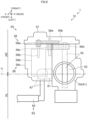
- FIG. 5 is a perspective view of the throttle device 51.
- FIG. 6 is a plan view of the throttle device 51.
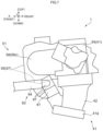
- FIG. 7 is a side view of the throttle device 51.
- the throttle device 51 includes a throttle valve 52.
- the throttle valve 52 is provided in the intake pipe 41.
- the throttle valve 52 opens and closes the intake pipe 41.
- the throttle valve 52 adjusts the amount of air flowing through the intake pipe 41.
- the throttle valve 52 is classified as, for example, a butterfly valve.
- the throttle valve 52 has, for example, a disk shape.
- the throttle valve 52 has, for example, a circular plate shape.
- the throttle device 51 includes a valve shaft 53.
- the valve shaft 53 supports the throttle valve 52.
- the valve shaft 53 is connected to the throttle valve 52.
- the throttle valve 52 is fixed to the valve shaft 53.
- the throttle valve 52 rotates integrally with the valve shaft 53.
- the throttle valve 52 rotates about the valve shaft 53.
- the throttle device 51 includes a throttle body 54.
- the throttle body 54 constitutes a section of the intake pipe 41.
- the throttle body 54 has a substantially tubular shape. The air flows in the throttle body 54.
- the throttle body 54 accommodates the throttle valve 52.
- the throttle body 54 supports the valve shaft 53.
- the throttle valve 52 is provided in the throttle body 54.
- the throttle valve 52 is rotatable with respect to the throttle body 54.
- the valve shaft 53 is also rotatable with respect to the throttle body 54.
- the throttle device 51 includes a gear box 55.
- the gear box 55 is coupled to the throttle valve 52.
- the gear box 55 is coupled to the throttle valve 52 via a valve shaft 53.
- the throttle device 51 includes a motor 58.
- the motor 58 is coupled to the gear box 55.
- the motor 58 is coupled to the throttle valve 52 via the gear box 55.
- the motor 58 generates power.
- the gear box 55 transmits the power of the motor 58 to the throttle valve 52.
- the motor 58 drives the throttle valve 52 via the gear box 55.
- the motor 58 opens and closes the throttle valve 52 via the gear box 55.
- the gear box 55 includes a gear mechanism 56.
- the gear mechanism 56 is coupled to the throttle valve 52.
- the gear mechanism 56 is coupled to the throttle valve 52 via a valve shaft 53.
- the gear mechanism 56 is coupled to the motor 58.
- the motor 58 is coupled to the throttle valve 52 via the gear mechanism 56.
- the motor 58 includes a motor body 58a and an output shaft 58b.
- the motor body 58a generates rotational power.
- the output shaft 58b is connected to the motor body 58a.
- the motor body 58a outputs rotational power to the output shaft 58b.
- the output shaft 58b rotates.
- the output shaft 58b is coupled to the gear mechanism 56.
- the gear mechanism 56 includes a first gear 56a, a second gear 56b, a third gear 56c, a fourth gear 56d, and an intermediate shaft 56e.
- the first gear 56a is fixed to the output shaft 58b.
- the first gear 56a rotates integrally with the output shaft 58b.
- the first gear 56a rotates about the output shaft 58b.
- the second gear 56b and the third gear 56c are fixed to each other.
- the second gear 56b and the third gear 56c are integrally molded.
- the second gear 56b and the third gear 56c are supported by the intermediate shaft 56e.
- the third gear 56c rotates integrally with the second gear 56b.
- the second gear 56b and the third gear 56c rotate about the intermediate shaft 56e.
- the second gear 56b and the third gear 56c rotate with respect to the intermediate shaft 56e.
- the fourth gear 56d is fixed to the valve shaft 53.
- the fourth gear 56d rotates integrally with the valve shaft 53.
- the fourth gear 56d rotates about the valve shaft 53.
- the first gear 56a meshes with the second gear 56b.
- the third gear 56c meshes with the fourth gear 56d.
- the first gear 56a rotates.
- the second gear 56b and the third gear 56c rotate.
- the fourth gear 56d rotates.
- the valve shaft 53 and the throttle valve 52 rotate.
- the motor 58 includes a motor case 58c.
- the motor case 58c accommodates the motor body 58a and the output shaft 58b.
- the motor case 58c is attached to the gear box 55.
- the motor case 58c is connected to the gear cover 57.
- the motor case 58c may be further joined to the throttle body 54.
- the motor case 58c may be formed integrally with the throttle body 54.
- the motor case 58c may be further attached to the throttle body 54.
- the motor case 58c may be connected to the throttle body 54.
- the motor 58 is disposed in front of the throttle body 54. At least a part of the motor 58 is disposed more forward than the entire throttle body 54. For example, the entire motor 58 is disposed more forward than the entire throttle body 54. The motor 58 does not overlap the throttle body 54 in vehicle side view. The motor 58 does not overlap the throttle body 54 in vehicle plan view. Although not illustrated, the motor 58 overlaps the throttle body 54 in vehicle front view.
- the gear box 55 is disposed at the same height position as the throttle valve 52. At least a part of the gear box 55 is disposed at the same height position as at least a part of the throttle valve 52.
- the gear box 55 is disposed rightward of the throttle valve 52.
- the entire gear box 55 is disposed more rightward than the entire throttle valve 52.
- the gear box 55 overlaps the throttle valve 52 in vehicle side view.
- the gear box 55 does not overlap the throttle valve 52 in vehicle plan view.
- the gear box 55 does not overlap the throttle valve 52 in vehicle front view.
- the gear box 55 is disposed rightward of the throttle body 54.
- the entire gear box 55 is disposed more rightward than the entire throttle body 54.
- the gear box 55 overlaps the throttle body 54 in vehicle side view.
- the gear box 55 is disposed at the same height position as the motor 58. At least a portion of the gear box 55 is disposed at the same height position as at least a portion of the motor 58.
- the gear box 55 is disposed rightward of the motor 58.
- the entire gear box 55 is disposed more rightward than the entire motor 58.
- the gear box 55 overlaps the motor 58 in vehicle side view.
- the gear box 55 overlaps the entire motor 58 in vehicle side view.
- the gear box 55 is connected to the right portion of the motor 58.
- the gear cover 57 is connected to the right portion of the motor case 58c.
- the right portion of the motor case 58c is open.
- the motor case 58c has a right opening (not illustrated).
- the right opening is located at the right portion of the motor case 58c.
- the gear cover 57 covers the right opening of the motor case 58c.
- the gear cover 57 closes the right opening of the motor case 58c.
- the gear box 55 extends in the longitudinal direction X.
- the gear box 55 extends forward from the throttle valve 52.
- the gear box 55 extends from the throttle valve 52 to the motor 58.
- the gear box 55 extends forward from the throttle body 54.
- the gear box 55 extends from the throttle body 54 to the motor 58.
- the gear box 55 extends from the right side of the throttle body 54 to the right side of the motor 58.
- the valve shaft 53 extends from the throttle valve 52 to the gear box 55.
- the valve shaft 53 extends from the throttle valve 52 to the gear mechanism 56.
- the valve shaft 53 penetrates the throttle body 54.
- the valve shaft 53 extends in the transverse direction Y.
- the valve shaft 53 extends rightward from the throttle valve 52.
- the second end 41b is inserted into the air cleaner 71.
- the second end 41b is disposed in the air cleaner 71.
- the intake pipe 41 communicates with the air cleaner 71 through the second end 41b.
- the intake pipe 41 includes a first pipe 42.
- the first pipe 42 extends from the engine 10 to the throttle body 54.
- the first pipe 42 extends from the cylinder head 14 to the throttle body 54.
- the first pipe 42 includes the first end 41a of the intake pipe 41.
- the first pipe 42 is connected to the engine 10.
- the first pipe 42 is connected to the cylinder head 14.
- the first pipe 42 is connected to the upper surface of the cylinder head 14.
- the first pipe 42 is connected to the intake passage 17.
- the first pipe 42 is connected to the intake connection port 17a.
- the first pipe 42 is connected to the throttle body 54.
- the first pipe 42 extends from the first end 41a of the intake pipe 41 to the throttle body 54.
- the first pipe 42 is connected to the throttle body 54 from the first end 41a of the intake pipe 41.
- the throttle body 54 is a section of the intake pipe 41. Therefore, the throttle body 54 is one element of the throttle device 51 and is also one element of the intake pipe 41. Therefore, it can also be said that "the intake pipe 41 includes the throttle body 54".
- the first end 41a is disposed outside the air cleaner 71.
- the first pipe 42 is disposed outside the air cleaner 71.
- the throttle body 54 is disposed outside the air cleaner 71.
- the throttle device 51 is disposed outside the air cleaner 71.
- the intake pipe 41 includes a second pipe 43.
- the second pipe 43 extends from the throttle body 54 to the air cleaner 71.
- the second pipe 43 is connected to the throttle body 54.
- the second pipe 43 includes the second end 41b of the intake pipe 41.
- the second pipe 43 is connected to the air cleaner 71.
- the second pipe 43 extends from the throttle body 54 to the second end 41b of the intake pipe 41.
- the second pipe 43 is inserted into the air cleaner 71 from the outside of the air cleaner 71.
- the second pipe 43 has an exterior portion 44 and an interior portion 45.
- the exterior portion 44 is located outside the air cleaner 71.
- the interior portion 45 is located in the air cleaner 71.
- the shape of the intake pipe 41 will be described.
- the intake pipe 41 extends upward from the first end 41a. Specifically, the intake pipe 41 extends upward from the engine 10. The intake pipe 41 extends upward from the cylinder head 14. Thereafter, the intake pipe 41 is curved forward. The intake pipe 41 extends forward. Thereafter, the intake pipe 41 is curved downward. The intake pipe 41 extends downward. Thereafter, the intake pipe 41 reaches the second end 41b.
- the second end 41b is disposed more forward than the first end 41a.
- the entire second end 41b is disposed more forward than the entire first end 41 a.
- the second end 41b is disposed higher than the first end 41a.
- the entire second end 41b is disposed higher than the entire first end 41a.
- the first end 41a corresponds to the lower end of the intake pipe 41.
- the second end 41b corresponds to the front end of the intake pipe 41.
- the shape of the first pipe 42 will be described.
- the first pipe 42 extends upward from the first end 41a. Specifically, the first pipe 42 extends upward from the engine 10. The first pipe 42 extends upward from the cylinder head 14.
- first pipe 42 extends upward and rearward from the engine 10.
- the first pipe 42 extends upward and rearward from the cylinder head 14.
- the first pipe 42 extends upward and rearward from the intake passage 17.
- the intake passage 17 extends downward and rearward from the first pipe 42.
- the first pipe 42 is disposed higher than the first end 41a.
- the entire first pipe 42 is disposed higher than at least a part of the first end 41a.
- the entire first pipe 42 is disposed higher than the entire first end 41a.
- the first pipe 42 is disposed more rearward than the second end 41b.
- the entire first pipe 42 is disposed more rearward than the entire second end 41b.
- the first pipe 42 is disposed lower than the second end 41b.
- the entire first pipe 42 is disposed lower than the entire second end 41b.
- a shape of the throttle body 54 will be described.
- the throttle body 54 extends upward from the first pipe 42.
- the throttle body 54 extends in the up-down direction Z.
- the throttle body 54 is disposed higher than the first end 41a.
- the entire throttle body 54 is disposed higher than the entire first end 41a.
- the throttle body 54 is disposed more rearward than the second end 41b.
- the entire throttle body 54 is disposed more rearward than the entire second end 41b.
- the throttle body 54 is disposed lower than the second end 41b.
- the entire throttle body 54 is disposed lower than the entire second end 41b.
- the throttle body 54 is disposed above the first pipe 42.
- the entire throttle body 54 is disposed higher than at least a part of the first pipe 42.
- the entire throttle body 54 is disposed higher than the entire first pipe 42.
- the second pipe 43 extends upward and forward from the throttle body 54.
- the exterior portion 44 extends upward from the throttle body 54 outside the air cleaner 71.
- the exterior portion 44 extends in the up-down direction Z.
- the second pipe 43 penetrates the air cleaner 71.
- the second pipe 43 penetrates the bottom of the air cleaner 71.
- the second pipe 43 enters the air cleaner 71 from the outside of the air cleaner 71.
- the interior portion 45 extends upward from the exterior portion 44.
- the interior portion 45 curves forward in the air cleaner 71.
- the interior portion 45 extends forward in the air cleaner 71.
- the interior portion 45 then curves downward in the air cleaner 71.
- the interior portion 45 extends downward in the air cleaner 71.
- the interior portion 45 extends upward and forward from the exterior portion 44.
- the interior portion 45 curves convexly upward in vehicle side view.
- the interior portion 45 reaches the second end 41b of the intake pipe 41.
- the interior portion 45 is opened into the air cleaner 71.
- the second pipe 43 is disposed higher than the first end 41a.
- the entire second pipe 43 is disposed higher than the entire first end 41a.
- the second pipe 43 is disposed more rearward than the second end 41b.
- the entire second pipe 43 is disposed more rearward than at least a part of the second end 41b.
- the entire second pipe 43 is disposed more rearward than the entire second end 41b.
- the second pipe 43 is disposed higher than the first pipe 42.
- the entire second pipe 43 is disposed higher than the entire first pipe 42.
- the second pipe 43 is disposed higher than the throttle body 54.
- the entire second pipe 43 is disposed higher than at least a part of the throttle body 54.
- the entire second pipe 43 is disposed higher than the entire throttle body 54.
- the exterior portion 44 is shorter than the first pipe 42.
- the exterior portion 44 is shorter than the throttle body 54.
- the exterior portion 44 is shorter than the interior portion 45.
- the interior portion 45 is longer than the first pipe 42.
- the interior portion 45 is longer than the throttle body 54.
- the interior portion 45 is longer than the exterior portion 44.
- FIG. 8 is a right side view of the air cleaner 71.
- the second pipe 43 has a first end 43a and a second end 43b.
- the first end 43a is connected to the throttle body 54.
- the second end 43b is the second end 41b of the intake pipe 41.
- the second pipe 43 extends from the first end 43a to the second end 43b.
- the second end 43b is disposed more forward than the first end 43a.
- the entire second end 43b is disposed more forward than the entire first end 43a.
- the second end 43b is disposed higher than the first end 43a.
- the entire second end 43b is disposed higher than the entire first end 43a.
- Fuel Injection Device 61 Fuel Pipe 63, and Fuel Tank 69
- the intake pipe 41 has a downstream portion.
- the downstream portion is a portion of the intake pipe 41 from the engine 10 to the throttle valve 52.
- the downstream portion is a portion of the intake pipe 41 located between the engine 10 and the throttle valve 52.
- the downstream portion includes, for example, the first pipe 42 and the throttle body 54.
- the downstream portion includes the entire first pipe 42.
- the downstream portion includes a part of the throttle body 54.
- the downstream portion includes a lower portion of the throttle body 54.
- the fuel injection device 61 is attached to the downstream portion of the intake pipe 41.
- the fuel injection device 61 is attached to the first pipe 42.
- the fuel pipe 63 has a first end 64.
- the first end 64 is connected to the fuel injection device 61.
- the first end 64 extends forward from the fuel injection device 61.
- the first end 64 extends in the longitudinal direction X.
- the straddled vehicle 1 includes a joint 67.
- the fuel injection device 61 and the fuel pipe 63 are connected via a joint 67.
- the joint 67 is attached to the fuel injection device 61.
- the fuel pipe 63 is attached to the joint 67.
- the first end 64 is attached to the joint 67.
- the fuel injection device 61 and the joint 67 are separable from each other.
- the joint 67 extends leftward from the fuel injection device 61.
- the joint 67 is provided above the fuel injection device 61.
- the joint 67 is connected to the fuel injection device 61.
- the joint 67 extends upward from the fuel injection device 61. Then, the joint 67 extends leftward. Then, the joint 67 extends forward.
- the first end 64 is disposed in front of the joint 67.
- the first end 64 is connected to the joint 67.
- the first end 64 extends forward from the joint 67.
- the first end 64 is disposed leftward of the fuel injection device 61.
- the entire first end 64 is disposed more leftward than the entire fuel injection device 61.
- the first end 64 does not overlap the fuel injection device 61 in vehicle plan view.
- the fuel pipe 63 is also referred to as a fuel hose.
- the fuel pipe 63 has flexibility.
- the fuel pipe 63 has a second end 65.
- the second end 65 is connected to the fuel tank 69.
- the second end 65 is connected to the fuel tank 69 via a fuel pump (not illustrated).
- the fuel tank 69 is a substantially closed container.
- the fuel tank 69 stores fuel.
- the air cleaner 71 includes an air cleaner case 72.
- the air cleaner case 72 is a substantially closed container.
- the air cleaner case 72 has a substantially box shape.
- the air cleaner case 72 includes an upper portion 72a and a lower portion 72b.
- the lower portion 72b is disposed below the upper portion 72a.
- the lower portion 72b is connected to the upper portion 72a.
- the upper portion 72a and the lower portion 72b are separable from each other.
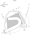
- FIG. 9 is a plan view illustrating the inside of the air cleaner 71.
- FIG. 9 omits illustration of the upper portion 72a.
- FIG. 10 is a left side view of the air cleaner 71.
- the air cleaner case 72 is indicated by a broken line.
- the air cleaner case 72 is indicated by a broken line.
- the first end 43a is disposed outside the air cleaner case 72.
- the second end 43b is disposed in the air cleaner case 72.
- the air cleaner case 72 forms an internal space 74.
- the internal space 74 is located inside the air cleaner case 72.
- the internal space 74 is located below the upper portion 72a.
- the internal space 74 is located above the lower portion 72b.
- the air cleaner 71 includes a filter 75.
- the filter 75 removes foreign substances from the air.
- the filter 75 is installed in the air cleaner case 72.
- the filter 75 partitions the internal space 74 into an upstream space 74a and a downstream space 74b.
- the filter 75 has a plate shape.
- the filter 75 extends in the longitudinal direction X.
- the filter 75 extends in the up-down direction Z.
- the upstream space 74a is located leftward of the filter 75.
- the downstream space 74b is located rightward of the filter 75.
- the intake pipe 41 is connected to the air cleaner case 72.
- the second pipe 43 is connected to the air cleaner case 72.
- the intake pipe 41 is connected to the lower portion 72b.
- the second pipe 43 is connected to the lower portion 72b.
- the intake pipe 41 penetrates the air cleaner case 72.
- the second pipe 43 penetrates the air cleaner case 72.
- the intake pipe 41 penetrates the lower portion 72b.
- the second pipe 43 penetrates the lower portion 72b.
- the interior portion 45 of the second pipe 43 is disposed in the internal space 74.
- the entire interior portion 45 is disposed in the internal space 74.
- the interior portion 45 is disposed in the downstream space 74b.
- the entire interior portion 45 is disposed in the downstream space 74b.
- the second end 41b of the intake pipe 41 is disposed in the internal space 74.
- the second end 43b of the second pipe 43 is disposed in the internal space 74.
- the second end 41b is disposed in the downstream space 74b.
- the second end 43b is disposed in the downstream space 74b.
- the intake pipe 41 is opened to the internal space 74.
- the second pipe 43 is opened to the internal space 74.
- the intake pipe 41 is opened to the downstream space 74b.
- the second pipe 43 is opened to the downstream space 74b.
- the air cleaner 71 has an intake port 76.
- the intake port 76 takes in air.
- the intake port 76 is opened to the outside of the air cleaner 71.
- the intake port 76 takes in air outside the air cleaner 71.
- the intake port 76 introduces air into the air cleaner 71.
- the internal space 74 communicates with the intake port 76.
- the internal space 74 communicates with an area outside the air cleaner 71 through the intake port 76.
- the intake port 76 introduces air outside the air cleaner 71 into the internal space 74.
- the upstream space 74a communicates with the intake port 76.
- the upstream space 74a communicates with an area outside the air cleaner 71 through the intake port 76.
- the intake port 76 introduces air outside the air cleaner 71 into the upstream space 74a.
- the intake port 76 is disposed at a front part of the air cleaner 71.
- the intake port 76 is opened to an area in front of the air cleaner 71.
- the intake port 76 takes in air in front of the air cleaner 71.
- the intake port 76 takes in air in the area in front of the air cleaner 71.
- the intake port 76 is disposed more forward than the intake pipe 41.
- the entire intake port 76 is disposed more forward than the entire intake pipe 41.
- the intake port 76 is disposed more forward than the second end 41b of the intake pipe 41.
- the entire intake port 76 is disposed more forward than the entire second end 41b.
- the intake port 76 is disposed lower than the second end 41b of the intake pipe 41.
- the entire intake port 76 is disposed lower than the entire second end 41b.
- the intake port 76 is disposed more forward than the second pipe 43.
- the entire intake port 76 is disposed more forward than the entire second pipe 43.
- the intake port 76 is disposed lower than the second pipe 43.
- the entire intake port 76 is disposed lower than the entire second pipe 43.
- the air cleaner 71 includes an intake duct 77.
- the intake duct 77 extends from the intake port 76 to the air cleaner 71.
- the intake duct 77 extends from the intake port 76 to the internal space 74.
- the internal space 74 communicates with the intake port 76 via the intake duct 77.
- the intake duct 77 extends from the intake port 76 to the upstream space 74a.
- the upstream space 74a communicates with the intake port 76 via the intake duct 77.
- the intake duct 77 extends rearward from the intake port 76.
- the intake duct 77 extends to the air cleaner 71.
- the intake duct 77 penetrates the air cleaner 71.
- the intake duct 77 penetrates a front part of the air cleaner 71.
- the intake duct 77 penetrates the air cleaner case 72.
- the intake duct 77 penetrates the lower portion 72b.
- the intake duct 77 is inserted into the air cleaner 71 from the outside of the air cleaner 71.
- the intake duct 77 is inserted into the internal space 74.
- the intake duct 77 is inserted into the upstream space 74a.
- the intake duct 77 extends rearward in the upstream space 74a. Then, the intake duct 77 is curved upward in the upstream space 74a. The intake duct 77 extends upward in the upstream space 74a. Then, the intake duct 77 is curved forward in the upstream space 74a. The intake duct 77 extends forward in the upstream space 74a. Then, the intake duct 77 is opened to the upstream space 74a.
- the intake port 76 is disposed more forward than the first end 41a of the intake pipe 41.
- the entire intake port 76 is disposed more forward than the entire first end 41a.
- the intake port 76 is disposed higher than the first end 41a.
- the entire intake port 76 is disposed higher than the entire first end 41a.
- the intake port 76 takes in air. Air enters the air cleaner 71 through the intake port 76. The air flows from the air cleaner 71 to the intake pipe 41. The amount of air flowing through the intake pipe 41 is adjusted by the throttle valve 52. Air flows from the intake pipe 41 to the engine 10. The fuel is supplied from the fuel tank 69 to the engine 10 through the fuel injection device 61.
- the intake port 76 takes in air in front of the air cleaner 71. Air enters the intake duct 77 through the intake port 76 from the area in front of the air cleaner 71. The air flows from the intake duct 77 to the upstream space 74a. The air flows from the upstream space 74a to the downstream space 74b through the filter 75.
- the filter 75 filters air. The filter 75 purifies air.
- the air flows from the downstream space 74b to the second pipe 43.
- the air flows from the second pipe 43 to the throttle body 54.
- the throttle valve 52 adjusts the amount of air flowing through the throttle body 54.
- the air flows from the throttle body 54 to the first pipe 42.
- the air flows from the first pipe 42 to the intake passage 17.
- the air flows downward and forward in the first pipe 42.
- the air flows downward and rearward in the intake passage 17.
- the air flows from the intake passage 17 to the cylinder bore 16.
- the air flows from the intake passage 17 to the combustion chamber.
- the fuel flows from the fuel tank 69 to the fuel pipe 63.
- Fuel flows from the fuel pipe 63 through the joint 67 to the fuel injection device 61.
- the fuel is supplied from the fuel injection device 61 to the downstream portion of the intake pipe 41.
- the fuel is injected from the fuel injection device 61.
- the fuel is injected into a downstream portion of the intake pipe 41.
- the fuel is injected into the first pipe 42, for example.
- the fuel is injected toward, for example, the intake connection port 17a.
- the fuel is injected toward, for example, the intake passage 17.
- the fuel is injected toward, for example, the intake valve 18.
- the fuel flows from the intake passage 17 to the cylinder bore 16 together with air.
- the fuel flows together with air from the intake passage 17 to the combustion chamber.
- the air may become air-fuel mixture that contains fuel in at least one of the downstream portion of the intake pipe 41 and the intake passage 17.
- the air-fuel mixture flows from the intake passage 17 to the cylinder bore 16.
- the air-fuel mixture flows from the intake passage 17 to the combustion chamber.
- the engine 10 is disposed below the seat 3. At least a part of the engine 10 is disposed below the seat 3. At least a part of the engine 10 is disposed lower than the entire seat 3. For example, the entire engine 10 is disposed lower than the entire seat 3. The engine 10 does not overlap the seat 3 in vehicle side view.
- the storage box 25 is disposed below the seat 3. At least a part of the storage box 25 is disposed below the seat 3. At least a part of the storage box 25 is disposed lower than the entire seat 3.
- the storage box 25 may have a portion overlapping the seat 3 in vehicle side view. Alternatively, the storage box 25 may not have a portion overlapping the seat 3 in vehicle side view.
- the storage box 25 has a first portion and a second portion.
- the first portion of the storage box 25 overlaps the seat 3 in vehicle side view.
- the second portion of the storage box 25 does not overlap the seat 3 in vehicle side view.
- the second portion of the storage box 25 is disposed below the seat 3.
- the second portion of the storage box 25 is disposed lower than the entire seat 3.
- the storage box 25 does not have a portion disposed higher than the seat 3.
- the storage box 25 is disposed above the engine 10. At least a part of the storage box 25 is disposed above the engine 10. At least a part of the storage box 25 is disposed higher than the entire engine 10. For example, the entire storage box 25 is disposed higher than the entire engine 10. The storage box 25 does not overlap the engine 10 in vehicle side view.
- the fuel pipe 63 is disposed below the seat 3. At least a part of the fuel pipe 63 is disposed lower than the entire seat 3. For example, the entire fuel pipe 63 is disposed lower than the entire seat 3. The fuel pipe 63 does not overlap the seat 3 in vehicle side view.
- the fuel pipe 63 is disposed in front of the engine 10. At least a part of the fuel pipe 63 is disposed more forward than the entire engine 10. For example, the second end 65 of the fuel pipe 63 is disposed more forward than the entire engine 10. The fuel pipe 63 does not overlap the engine 10 in vehicle side view.
- the fuel pipe 63 is disposed in front of the crankcase 11. At least a part of the fuel pipe 63 is disposed more forward than the entire crankcase 11. For example, the entire fuel pipe 63 is disposed more forward than the entire crankcase 11. The fuel pipe 63 does not overlap the crankcase 11 in vehicle side view.
- the fuel pipe 63 is disposed in front of the cylinder body 13. At least a part of the fuel pipe 63 is disposed more forward than the entire cylinder body 13. For example, the entire fuel pipe 63 is disposed more forward than the entire cylinder body 13. The fuel pipe 63 does not overlap the cylinder body 13 in vehicle side view.
- the fuel pipe 63 is disposed in front of the storage box 25. At least a part of the fuel pipe 63 is disposed more forward than the entire storage box 25. For example, the entire fuel pipe 63 is disposed more forward than the entire storage box 25. The fuel pipe 63 does not overlap the storage box 25 in vehicle side view.
- the fuel tank 69 is disposed lower than the seat 3. At least a part of the fuel tank 69 is disposed lower than the entire seat 3. For example, the entire fuel tank 69 is disposed lower than the entire seat 3. The fuel tank 69 does not overlap the seat 3 in vehicle side view.
- the fuel tank 69 is disposed in front of the engine 10. At least a part of the fuel tank 69 is disposed more forward than the entire engine 10. For example, the entire fuel tank 69 is disposed more forward than the entire engine 10. The fuel tank 69 does not overlap the engine 10 in vehicle side view.
- the fuel tank 69 is disposed at the same height position as the engine 10. At least a part of the fuel tank 69 is disposed at the same height position as at least a part of the engine 10. Although not illustrated, the fuel tank 69 overlaps the engine 10 in vehicle front view.
- the fuel tank 69 is disposed in front of the cylinder head 14. At least a part of the fuel tank 69 is disposed more forward than the entire cylinder head 14. For example, the entire fuel tank 69 is disposed more forward than the entire cylinder head 14. The fuel tank 69 does not overlap the cylinder head 14 in vehicle side view.
- the fuel tank 69 is disposed at the same height position as the cylinder head 14. At least a part of the fuel tank 69 is disposed at the same height position as at least a part of the cylinder head 14. Although not illustrated, the fuel tank 69 overlaps the cylinder head 14 in vehicle front view.
- the fuel tank 69 extends from a position higher than the cylinder head 14 to a position lower than the cylinder head 14.
- the fuel tank 69 extends from a position higher than the entire cylinder head 14 to a position lower than the entire cylinder head 14.
- the fuel tank 69 has a portion located higher than the entire cylinder head 14, a portion located at the same height position as the cylinder head 14, and a portion located lower than the entire cylinder head 14.
- the fuel tank 69 is disposed in front of the storage box 25. At least a part of the fuel tank 69 is disposed more forward than the entire storage box 25. For example, the entire fuel tank 69 is disposed more forward than the entire storage box 25. The fuel tank 69 does not overlap the storage box 25 in vehicle side view.
- the air cleaner 71 is disposed below the seat 3. At least a part of the air cleaner 71 is disposed below the seat 3. At least a part of the air cleaner 71 is disposed lower than the entire seat 3.
- the air cleaner 71 may have a portion overlapping the seat 3 in vehicle side view.
- the upper portion 72a of the air cleaner case 72 overlaps the seat 3 in vehicle side view.
- at least a part of the lower portion 72b is disposed lower than the entire seat 3.
- the lower portion 72b of the air cleaner case 72 may have a portion overlapping the seat 3 in vehicle side view.
- the lower portion 72b of the air cleaner case 72 may not overlap the seat 3 in vehicle side view.
- the air cleaner 71 does not have a portion disposed higher than the entire seat 3.
- the air cleaner 71 is disposed above the engine 10. At least a part of the air cleaner 71 is disposed above the engine 10. At least a part of the air cleaner 71 is disposed higher than the entire engine 10. For example, the entire air cleaner 71 is disposed higher than the entire engine 10. The air cleaner 71 does not overlap the engine 10 in vehicle side view.
- the air cleaner 71 is disposed above the cylinder head 14. At least a part of the air cleaner 71 is disposed above the cylinder head 14. At least a part of the air cleaner 71 is disposed higher than the entire cylinder head 14. For example, the entire air cleaner 71 is disposed higher than the entire cylinder head 14. The air cleaner 71 does not overlap the cylinder head 14 in vehicle side view.
- the air cleaner 71 is disposed in front of the storage box 25. At least a part of the air cleaner 71 is disposed in front of the storage box 25. At least a part of the air cleaner 71 is disposed more forward than the entire storage box 25. For example, the air cleaner 71 may have a portion overlapping the storage box 25 in vehicle side view.
- the air cleaner 71 does not have a portion located more rearward than the entire storage box 25.
- At least a part of the storage box 25 is disposed more rearward than the entire air cleaner 71.
- the air cleaner 71 is disposed at the same height position as the storage box 25. At least a part of the air cleaner 71 is disposed at the same height position as at least a part of the storage box 25.
- the air cleaner 71 is disposed above the fuel pipe 63.
- the air cleaner 71 is disposed behind the fuel tank 69. At least a part of the air cleaner 71 is disposed more rearward than the entire fuel tank 69.
- the air cleaner 71 is disposed at the same height position as the fuel tank 69. At least a part of the air cleaner 71 is disposed at the same height position as at least a part of the fuel tank 69.
- the fuel tank 69 has a portion located in front of the air cleaner 71.
- the fuel tank 69 has a portion located more forward than the entire air cleaner 71. Further, the fuel tank 69 has a portion located lower than the air cleaner 71.
- the fuel tank 69 has a portion located lower than the entire air cleaner 71.
- the intake port 76 is disposed below the seat 3. At least a part of the intake port 76 is disposed lower than the entire seat 3. For example, the entire intake port 76 is disposed lower than the entire seat 3. The intake port 76 does not overlap the seat 3 in vehicle side view.
- the intake port 76 is disposed higher than the engine 10. At least a part of the intake port 76 is disposed higher than the entire engine 10. For example, the entire intake port 76 is disposed higher than the entire engine 10. The intake port 76 does not overlap the engine 10 in vehicle side view.
- the intake port 76 is disposed higher than the cylinder head 14. At least a part of the intake port 76 is disposed higher than the entire cylinder head 14. For example, the entire intake port 76 is disposed higher than the entire cylinder head 14. The intake port 76 does not overlap the cylinder head 14 in vehicle side view.
- the intake port 76 is disposed more forward than the engine 10. At least a part of the intake port 76 is disposed more forward than the entire engine 10. For example, the entire intake port 76 is disposed more forward than the entire engine 10.
- the intake port 76 is disposed more forward than the crankcase 11. At least a part of the intake port 76 is disposed more forward than the entire crankcase 11. For example, the entire intake port 76 is disposed more forward than the entire crankcase 11.
- the intake port 76 is disposed more forward than the cylinder unit 12. At least a part of the intake port 76 is disposed more forward than the entire cylinder unit 12. For example, the entire intake port 76 is disposed more forward than the entire cylinder unit 12.
- the intake port 76 is disposed more forward than the cylinder body 13. At least a part of the intake port 76 is disposed more forward than the entire cylinder body 13. For example, the entire intake port 76 is disposed more forward than the entire cylinder body 13.
- the intake port 76 is disposed more forward than the cylinder head 14. At least a part of the intake port 76 is disposed more forward than the entire cylinder head 14. For example, the entire intake port 76 is disposed more forward than the entire cylinder head 14.
- the intake port 76 is disposed more forward than the head cover 15. At least a part of the intake port 76 is disposed more forward than the entire head cover 15. For example, the entire intake port 76 is disposed more forward than the entire head cover 15.
- the intake port 76 is disposed more forward than the storage box 25. At least a part of the intake port 76 is disposed more forward than the entire storage box 25. For example, the entire intake port 76 is disposed more forward than the entire storage box 25.
- the intake port 76 is disposed at the same height position as the storage box 25. At least a part of the intake port 76 is disposed at the same height position as at least a part of the storage box 25.
- the intake port 76 is disposed behind the fuel tank 69.
- the intake port 76 is disposed at the same height position as the fuel tank 69. At least a part of the intake port 76 is disposed at the same height position as at least a part of the fuel tank 69.
- the fuel tank 69 has a portion located in front of the intake port 76.
- the fuel tank 69 has a portion located more forward than the entire intake port 76. Further, the fuel tank 69 has a portion located lower than the intake port 76.
- the fuel tank 69 has a portion located lower than the entire intake port 76.
- FIG. 11 is a plan view of the straddled vehicle 1.
- the seat 3 is indicated by a broken line.
- the storage box 25 overlaps the seat 3 in vehicle plan view. At least a part of the storage box 25 overlaps the seat 3 in vehicle plan view. For example, the entire storage box 25 overlaps the seat 3 in vehicle plan view.
- the seat 3 has a front end 3a. At least a part of the storage box 25 is disposed more rearward than the front end 3a. For example, the entire storage box 25 is disposed more rearward than the front end 3a.
- the air cleaner 71 overlaps the seat 3 in vehicle plan view. At least a part of the air cleaner 71 overlaps the seat 3 in vehicle plan view. For example, the entire air cleaner 71 overlaps the seat 3 in vehicle plan view.
- At least a part of the air cleaner 71 is disposed more rearward than the front end 3a.
- the entire air cleaner 71 is disposed more rearward than the front end 3a.
- the fuel tank 69 is disposed more forward than the seat 3. At least a part of the fuel tank 69 is disposed more forward than the entire seat 3. For example, the fuel tank 69 may have a portion overlapping the seat 3 in vehicle plan view.
- the fuel tank 69 does not have a portion disposed more rearward than the entire seat 3.
- the fuel tank 69 is disposed in front of the storage box 25. At least a part of the fuel tank 69 is disposed more forward than the entire storage box 25. For example, the entire fuel tank 69 is disposed more forward than the entire storage box 25. The fuel tank 69 does not overlap the storage box 25 in vehicle plan view.
- the fuel tank 69 is disposed in front of the air cleaner 71. At least a part of the fuel tank 69 is disposed more forward than the entire air cleaner 71.
- the fuel tank 69 may have a portion overlapping the air cleaner 71 in vehicle plan view.
- the fuel tank 69 has a third portion and a fourth portion.
- the third portion of the fuel tank 69 overlaps the air cleaner 71 in vehicle plan view.
- the fourth portion of the fuel tank 69 does not overlap the air cleaner 71 in vehicle plan view.
- the fourth portion of the fuel tank 69 is disposed more forward than the entire air cleaner 71.
- the fourth portion of the fuel tank 69 is disposed in front of the air cleaner 71 in vehicle plan view.
- the third portion of the fuel tank 69 is a part of the first portion of the fuel tank 69.
- a part of the fourth portion of the fuel tank 69 is the second portion of the fuel tank 69.
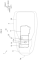
- FIG. 12 is a plan view of the straddled vehicle 1.
- the seat 3, the air cleaner 71, and the storage box 25 are indicated by broken lines.
- FIG. 12 illustrates the engine 10.
- the engine 10 overlaps the seat 3 in vehicle plan view. At least a part of the engine 10 overlaps the seat 3 in vehicle plan view. For example, the entire engine 10 overlaps the seat 3 in vehicle plan view.
- the engine 10 is disposed more rearward than the front end 3a of the seat 3. At least a part of the engine 10 is disposed more rearward than the front end 3a of the seat 3. For example, the entire engine 10 is disposed more rearward than the front end 3a.
- crankcase 11 overlaps the seat 3 in vehicle plan view. At least a part of the crankcase 11 overlaps the seat 3 in vehicle plan view. For example, the entire crankcase 11 overlaps the seat 3 in vehicle plan view.
- the crankcase 11 is disposed more rearward than the front end 3a. At least a part of the crankcase 11 is disposed more rearward than the front end 3a. For example, the entire crankcase 11 is disposed more rearward than the front end 3a.
- the cylinder unit 12 overlaps the seat 3 in vehicle plan view. At least a part of the cylinder unit 12 overlaps the seat 3 in vehicle plan view. For example, the entire cylinder unit 12 overlaps the seat 3 in vehicle plan view.
- the cylinder unit 12 is disposed more rearward than the front end 3a. At least a part of the cylinder unit 12 is disposed more rearward than the front end 3a. For example, the entire cylinder unit 12 is disposed more rearward than the front end 3a.
- the cylinder body 13 overlaps the seat 3 in vehicle plan view. At least a part of the cylinder body 13 overlaps the seat 3 in vehicle plan view. For example, the entire cylinder body 13 overlaps the seat 3 in vehicle plan view.
- the cylinder body 13 is disposed more rearward than the front end 3a. At least a part of the cylinder body 13 is disposed more rearward than the front end 3a. For example, the entire cylinder body 13 is disposed more rearward than the front end 3a.
- the cylinder head 14 overlaps the seat 3 in vehicle plan view. At least a part of the cylinder head 14 overlaps the seat 3 in vehicle plan view. For example, the entire cylinder head 14 overlaps the seat 3 in vehicle plan view.
- the cylinder head 14 is disposed more rearward than the front end 3a. At least a part of the cylinder head 14 is disposed more rearward than the front end 3a. For example, the entire cylinder head 14 is disposed more rearward than the front end 3a.
- FIG. 12 clearly illustrates the intake connection port 17a.
- the intake connection port 17a overlaps the seat 3 in vehicle plan view. At least a part of the intake connection port 17a overlaps the seat 3 in vehicle plan view. For example, the entire intake connection port 17a overlaps the seat 3 in vehicle plan view.
- the intake connection port 17a is disposed more rearward than the front end 3a. At least a part of the intake connection port 17a is disposed more rearward than the front end 3a. For example, the entire intake connection port 17a is disposed more rearward than the front end 3a.
- the head cover 15 overlaps the seat 3 in vehicle plan view. At least a part of the head cover 15 overlaps the seat 3 in vehicle plan view. For example, the entire head cover 15 overlaps the seat 3 in vehicle plan view.
- the head cover 15 is disposed more rearward than the front end 3a. At least a part of the head cover 15 is disposed more rearward than the front end 3a. For example, the entire head cover 15 is disposed more rearward than the front end 3a.
- the storage box 25 overlaps the engine 10 in vehicle plan view.
- the storage box 25 overlaps at least a part of the engine 10 in vehicle plan view.
- the storage box 25 overlaps only a part of the engine 10 in vehicle plan view.
- the storage box 25 extends to a position more rearward than the engine 10.
- the storage box 25 extends to a position more rearward than the entire engine 10.
- the storage box 25 has a portion located more rearward than the engine 10.
- the storage box 25 has a portion located more rearward than the entire engine 10.
- a part of the storage box 25 does not overlap the engine 10 in vehicle plan view.
- a part of the storage box 25 is disposed behind the engine 10 in vehicle plan view.
- a part of the storage box 25 is disposed behind the entire engine 10 in vehicle plan view.
- the storage box 25 does not have a portion located more forward than the entire engine 10.
- the storage box 25 overlaps the crankcase 11 in vehicle plan view.
- the storage box 25 overlaps at least a part of the crankcase 11 in vehicle plan view.
- the storage box 25 overlaps the entire crankcase 11 in vehicle plan view.
- the storage box 25 overlaps the cylinder unit 12 in vehicle plan view.
- the storage box 25 overlaps at least a part of the cylinder unit 12 in vehicle plan view.
- the storage box 25 overlaps only a part of the cylinder unit 12 in vehicle plan view.
- the storage box 25 overlaps the cylinder body 13 in vehicle plan view.
- the storage box 25 overlaps at least a part of the cylinder body 13 in vehicle plan view.
- the storage box 25 overlaps the entire cylinder body 13 in vehicle plan view.
- the storage box 25 overlaps the cylinder head 14 in vehicle plan view.
- the storage box 25 overlaps at least a part of the cylinder head 14 in vehicle plan view.
- the storage box 25 overlaps only a part of the cylinder head 14 in vehicle plan view.
- the storage box 25 overlaps the intake connection port 17a in vehicle plan view.
- the storage box 25 overlaps at least a part of the intake connection port 17a in vehicle plan view.
- the storage box 25 overlaps only a part of the intake connection port 17a in vehicle plan view.
- the storage box 25 does not overlap the head cover 15 in vehicle plan view.
- the storage box 25 is disposed more rearward than the head cover 15.
- the entire storage box 25 is disposed more rearward than the entire head cover 15.
- the air cleaner 71 overlaps the engine 10 in vehicle plan view.
- the air cleaner 71 overlaps at least a part of the engine 10 in vehicle plan view.
- the air cleaner 71 overlaps only a part of the engine 10 in vehicle plan view.
- the air cleaner 71 extends to a position more forward than the engine 10.
- the air cleaner 71 extends to a position more forward than the entire engine 10.
- the air cleaner 71 has a portion located more forward than the engine 10. Specifically, the air cleaner 71 has a portion located more forward than the entire engine 10.
- a part of the air cleaner 71 does not overlap the engine 10 in vehicle plan view.
- a part of the air cleaner 71 is disposed in front of the engine 10 in vehicle plan view.
- a part of the air cleaner 71 is disposed in front of the entire engine 10 in vehicle plan view.
- the air cleaner 71 does not have a portion located more rearward than the entire engine 10.
- the air cleaner 71 is disposed in front of the crankcase 11. At least a part of the air cleaner 71 is disposed in front of the crankcase 11. For example, the entire air cleaner 71 is disposed more forward than the entire crankcase 11. The air cleaner 71 does not overlap the crankcase 11 in vehicle plan view.
- the air cleaner 71 overlaps the cylinder unit 12 in vehicle plan view.
- the air cleaner 71 overlaps at least a part of the cylinder unit 12 in vehicle plan view.
- the air cleaner 71 overlaps only a part of the cylinder unit 12 in vehicle plan view.
- the air cleaner 71 overlaps the cylinder body 13 in vehicle plan view.
- the air cleaner 71 overlaps at least a part of the cylinder body 13 in vehicle plan view.
- the air cleaner 71 overlaps only a part of the cylinder body 13 in vehicle plan view.
- the air cleaner 71 overlaps the intake connection port 17a in vehicle plan view.
- the air cleaner 71 overlaps at least a part of the intake connection port 17a in vehicle plan view.
- the air cleaner 71 overlaps the entire intake connection port 17a in vehicle plan view.
- the air cleaner 71 extends to a position more forward than the cylinder head 14.
- the air cleaner 71 extends to a position more forward than the entire cylinder head 14.
- the air cleaner 71 has a portion located more forward than the cylinder head 14. Specifically, the air cleaner 71 has a portion located more forward than the entire cylinder head 14.
- a part of the air cleaner 71 does not overlap the cylinder head 14 in vehicle plan view.
- a part of the air cleaner 71 is disposed in front of the cylinder head 14 in vehicle plan view.
- a part of the air cleaner 71 is disposed in front of the entire cylinder head 14 in vehicle plan view.
- the air cleaner 71 overlaps the head cover 15 in vehicle plan view.
- the air cleaner 71 overlaps at least a part of the head cover 15 in vehicle plan view.
- the air cleaner 71 overlaps the entire head cover 15 in vehicle plan view.
- the air cleaner 71 extends to a position more forward than the head cover 15.
- the air cleaner 71 extends to a position more forward than the entire head cover 15.
- the air cleaner 71 has a portion located more forward than the head cover 15. Specifically, the air cleaner 71 has a portion located more forward than the entire head cover 15.
- a part of the air cleaner 71 does not overlap the head cover 15 in vehicle plan view.
- a part of the air cleaner 71 is disposed in front of the head cover 15 in vehicle plan view.
- a part of the air cleaner 71 is disposed in front of the entire head cover 15 in vehicle plan view.
- the fuel tank 69 is not illustrated in FIG. 12 , the fuel tank 69 does not overlap the engine 10 in vehicle plan view.
- the fuel tank 69 is disposed more forward than the engine 10.
- the entire fuel tank 69 is disposed more forward than the entire engine 10.
- the intake pipe 41 is disposed below the seat 3. At least a part of the intake pipe 41 is disposed below the seat 3. At least a part of the intake pipe 41 is disposed lower than the entire seat 3. For example, the intake pipe 41 may have a portion overlapping the seat 3 in vehicle side view.
- the first end 41a is disposed below the seat 3. At least a part of the first end 41a is disposed lower than the entire the seat 3. For example, the entire first end 41a is disposed lower than the entire seat 3. The first end 41a does not overlap the seat 3 in vehicle side view.
- the second end 41b is disposed below the seat 3. At least a part of the second end 41b is disposed lower than the entire seat 3. For example, the entire second end 41b is disposed lower than the entire seat 3. The second end 41b does not overlap the seat 3 in vehicle side view.
- the first pipe 42 is disposed below the seat 3. At least a part of the first pipe 42 is disposed below the seat 3. For example, the entire first pipe 42 is disposed lower than the entire seat 3. The first pipe 42 does not overlap the seat 3 in vehicle side view.
- the throttle body 54 is disposed below the seat 3. At least a part of the throttle body 54 is disposed lower than the entire seat 3. For example, the entire throttle body 54 is disposed lower than the entire seat 3. The throttle body 54 does not overlap the seat 3 in vehicle side view.
- the second pipe 43 overlaps the seat 3 in vehicle side view.
- a part of the second pipe 43 overlaps the seat 3 in vehicle side view.
- the interior portion 45 overlaps the seat 3 in vehicle side view.
- a part of the interior portion 45 overlaps the seat 3 in vehicle side view.
- the exterior portion 44 does not overlap the seat 3 in vehicle side view.
- the exterior portion 44 is disposed below the seat 3.
- the entire exterior portion 44 is disposed lower than the entire seat 3.
- the intake pipe 41 does not have a portion disposed higher than the entire seat 3.
- the intake pipe 41 is disposed above the engine 10. At least a part of the intake pipe 41 is disposed above the engine 10. At least a part of the intake pipe 41 is disposed higher than the entire engine 10. At least a part of the intake pipe 41 is disposed higher than the upper end 11a of the crankcase 11. For example, the intake pipe 41 has a portion disposed higher than the upper end 11a and a portion disposed lower than the upper end 11a.
- At least a part of the first end 41a of the intake pipe 41 is disposed lower than the upper end 11a.
- the entire first end 41a is disposed lower than the upper end 11a.
- At least a part of the second end 41b of the intake pipe 41 is disposed higher than the upper end 11a.
- the entire second end 41b is disposed higher than the upper end 11a.
- At least a part of the first pipe 42 is disposed higher than the upper end 11a.
- the first pipe 42 has a portion disposed higher than the upper end 11a and a portion disposed lower than the upper end 11a.
- At least a part of the throttle body 54 is disposed higher than the upper end 11a.
- the entire throttle body 54 is disposed higher than the upper end 11a.
- At least a part of the second pipe 43 is disposed higher than the upper end 11a.
- the entire second pipe 43 is disposed higher than the upper end 11a.
- the intake pipe 41 is disposed above the cylinder head 14. At least a part of the intake pipe 41 is disposed above the cylinder head 14. At least a part of the intake pipe 41 is disposed higher than the entire cylinder head 14. For example, the entire intake pipe 41 is disposed higher than the entire cylinder head 14.
- the second end 41b of the intake pipe 41 is disposed above the cylinder head 14. At least a part of the second end 41b is disposed above the cylinder head 14. At least a part of the second end 41b is disposed higher than the entire cylinder head 14. For example, the entire second end 41b is disposed higher than the entire cylinder head 14.
- the first pipe 42 is disposed above the cylinder head 14. At least a part of the first pipe 42 is disposed higher than the entire cylinder head 14. For example, the entire first pipe 42 is disposed higher than the entire cylinder head 14.
- the throttle body 54 is disposed above the cylinder head 14. At least a part of the throttle body 54 is disposed higher than the entire cylinder head 14. For example, the entire throttle body 54 is disposed higher than the entire cylinder head 14.
- the second pipe 43 is disposed above the cylinder head 14. At least a part of the second pipe 43 is disposed higher than the entire cylinder head 14. For example, the entire second pipe 43 is disposed higher than the entire cylinder head 14.
- the intake pipe 41 is disposed more forward than the engine 10. At least a part of the intake pipe 41 is disposed more forward than the entire engine 10.
- the second end 41b of the intake pipe 41 is disposed more forward than the engine 10. At least a part of the second end 41b is disposed more forward than the entire engine 10. For example, the entire second end 41b is disposed more forward than the entire engine 10. The second end 41b does not overlap the engine 10 in vehicle side view.
- the intake pipe 41 is disposed more forward than the crankcase 11. At least a part of the intake pipe 41 is disposed more forward than the entire crankcase 11. For example, the entire intake pipe 41 is disposed more forward than the entire crankcase 11. The intake pipe 41 does not overlap the crankcase 11 in vehicle side view.
- the first end 41a of the intake pipe 41 is disposed more forward than the crankcase 11. At least a part of the first end 41a is disposed more forward than the entire crankcase 11. For example, the entire first end 41a is disposed more forward than the entire crankcase 11. The first end 41a does not overlap the crankcase 11 in vehicle side view.
- the second end 41b of the intake pipe 41 is disposed more forward than the crankcase 11. At least a part of the second end 41b is disposed more forward than the entire crankcase 11. For example, the entire second end 41b is disposed more forward than the entire crankcase 11. The second end 41b does not overlap the crankcase 11 in vehicle side view.
- the first pipe 42 is disposed more forward than the crankcase 11.
- the first pipe 42 is disposed more forward than the entire crankcase 11.
- the entire first pipe 42 is disposed more forward than the entire crankcase 11.
- the first pipe 42 does not overlap the crankcase 11 in vehicle side view.
- the throttle body 54 is disposed more forward than the crankcase 11.
- the throttle body 54 is disposed more forward than the entire crankcase 11.
- the entire throttle body 54 is disposed more forward than the entire crankcase 11.
- the throttle body 54 does not overlap the crankcase 11 in vehicle side view.
- the second pipe 43 is disposed more forward than the crankcase 11.
- the second pipe 43 is disposed more forward than the entire crankcase 11.
- the entire second pipe 43 is disposed more forward than the entire crankcase 11.
- the second pipe 43 does not overlap the crankcase 11 in vehicle side view.
- the intake pipe 41 is disposed more forward than the cylinder head 14. At least a part of the intake pipe 41 is disposed more forward than the entire cylinder head 14.
- the second end 41b of the intake pipe 41 is disposed more forward than the cylinder head 14. At least a part of the second end 41b is disposed more forward than the entire cylinder head 14. For example, the entire second end 41b is disposed more forward than the entire cylinder head 14.
- the intake pipe 41 is disposed in front of the storage box 25. At least a part of the intake pipe 41 is disposed in front of the storage box 25. At least a part of the intake pipe 41 is disposed more forward than the entire storage box 25. In other words, the storage box 25 includes the front end 25a. At least a part of the intake pipe 41 is disposed more forward than the front end 25a. For example, the intake pipe 41 has a portion located more forward than the front end 25a and a portion located more rearward than the front end 25a. The intake pipe 41 does not overlap the storage box 25 in vehicle side view.
- the first end 41a of the intake pipe 41 is disposed in front of the storage box 25. At least a part of the first end 41a is disposed in front of the storage box 25. At least a part of the first end 41a is disposed more forward than the entire storage box 25. In other words, at least a part of the first end 41a is disposed more forward than the front end 25a. For example, the first end 41a has a portion located more forward than the front end 25a and a portion located more rearward than the front end 25a. The first end 41a does not overlap the storage box 25 in vehicle side view.
- the second end 41b of the intake pipe 41 is disposed in front of the storage box 25. At least a part of the second end 41b is disposed in front of the storage box 25. At least a part of the second end 41b is disposed more forward than the entire storage box 25. In other words, at least a part of the second end 41b is disposed more forward than the front end 25a. For example, the entire second end 41b is disposed more forward than the entire storage box 25. The entire second end 41b is disposed more forward than the front end 25a. The second end 41b does not overlap the storage box 25 in vehicle side view.
- the first pipe 42 is disposed in front of the storage box 25. At least a part of the first pipe 42 is disposed in front of the storage box 25. At least a part of the first pipe 42 is disposed more forward than the entire storage box 25. In other words, at least a part of the first pipe 42 is disposed more forward than the front end 25a. For example, the first pipe 42 has a portion located more forward than the front end 25a and a portion located more rearward than the front end 25a. The first pipe 42 does not overlap the storage box 25 in vehicle side view.
- the throttle body 54 is disposed in front of the storage box 25. At least a part of the throttle body 54 is disposed in front of the storage box 25. At least a part of the throttle body 54 is disposed more forward than the entire storage box 25. In other words, at least a part of the throttle body 54 is disposed more forward than the front end 25a. For example, the throttle body 54 has a portion located more forward than the front end 25a and a portion located more rearward than the front end 25a. The throttle body 54 does not overlap the storage box 25 in vehicle side view.
- the second pipe 43 is disposed in front of the storage box 25. At least a part of the second pipe 43 is disposed in front of the storage box 25. At least a part of the second pipe 43 is disposed more forward than the entire storage box 25. In other words, at least a part of the second pipe 43 is disposed more forward than the front end 25a.
- the second pipe 43 has a portion located more forward than the front end 25a and a portion located more rearward than the front end 25a. The second pipe 43 does not overlap the storage box 25 in vehicle side view.
- the storage box 25 is disposed behind the intake pipe 41. At least a part of the storage box 25 is disposed more rearward than the entire intake pipe 41.
- the intake pipe 41 is disposed at the same height position as the storage box 25. At least a part of the intake pipe 41 is disposed at the same height position as at least a part of the storage box 25.
- the storage box 25 has a lower end 25b. At least a part of the intake pipe 41 is disposed higher than the lower end 25b. For example, the intake pipe 41 has a portion located higher than the lower end 25b and a portion located lower than the lower end 25b.
- At least a part of the first end 41a of the intake pipe 41 is located lower than the lower end 25b.
- the entire first end 41a is located lower than the lower end 25b.
- At least a part of the second end 41b of the intake pipe 41 is located higher than the lower end 25b.
- the entire second end 41b is located higher than the lower end 25b.
- At least a part of the first pipe 42 is disposed higher than the lower end 25b.
- the first pipe 42 has a portion located higher than the lower end 25b and a portion located lower than the lower end 25b.
- At least a part of the throttle body 54 is disposed higher than the lower end 25b.
- the entire throttle body 54 is disposed higher than the lower end 25b.
- At least a part of the second pipe 43 is disposed higher than the lower end 25b.
- the entire second pipe 43 is disposed higher than the lower end 25b.
- At least a part of the air cleaner 71 is disposed higher than the lower end 25b.
- the entire air cleaner 71 is disposed higher than the lower end 25b.
- the intake pipe 41 is disposed below the air cleaner 71.
- at least a part of the intake pipe 41 is disposed below the air cleaner 71.
- at least a part of the intake pipe 41 is disposed lower than the entire air cleaner 71.
- the intake pipe 41 may have a portion overlapping the air cleaner 71 in vehicle side view.
- the first pipe 42 is disposed below the air cleaner 71.
- at least a part of the first pipe 42 is disposed lower than the entire air cleaner 71.
- the entire first pipe 42 is disposed lower than the entire air cleaner 71.
- the first pipe 42 does not overlap the air cleaner 71 in vehicle side view.
- the throttle body 54 is disposed below the air cleaner 71.
- at least a part of the throttle body 54 is disposed lower than the air cleaner 71.
- the entire throttle body 54 is disposed lower than the entire air cleaner 71.
- the throttle body 54 does not overlap the air cleaner 71 in vehicle side view.
- the second pipe 43 overlaps the air cleaner 71 in vehicle side view. At least a part of the second pipe 43 overlaps the air cleaner 71 in vehicle side view.
- the interior portion 45 overlaps the air cleaner 71 in vehicle side view.
- the entire interior portion 45 overlaps the air cleaner 71 in vehicle side view.
- the exterior portion 44 does not overlap the air cleaner 71 in vehicle side view.
- the exterior portion 44 is disposed below the air cleaner 71. At least a part of the exterior portion 44 is disposed lower than the air cleaner 71.
- the intake pipe 41 does not have a portion disposed higher than the entire air cleaner 71.
- the disposing position of the throttle device 51 will be described.
- the throttle device 51 is disposed below the seat 3. At least a part of the throttle device 51 is disposed lower than the entire seat 3. For example, the entire throttle device 51 is disposed lower than the entire seat 3. The throttle device 51 does not overlap the seat 3 in vehicle side view.
- the throttle valve 52 is disposed below the seat 3. At least a part of the throttle valve 52 is disposed lower than the entire seat 3. For example, the entire throttle valve 52 is disposed lower than the entire seat 3. The throttle valve 52 does not overlap the seat 3 in vehicle side view.
- the throttle body 54 is disposed below the seat 3. At least a part of the throttle body 54 is disposed lower than the entire seat 3. For example, the entire throttle body 54 is disposed lower than the entire seat 3. The throttle body 54 does not overlap the seat 3 in vehicle side view.
- the gear box 55 is disposed below the seat 3. At least a part of the gear box 55 is disposed lower than the entire seat 3. For example, the entire gear box 55 is disposed lower than the entire seat 3. The gear box 55 does not overlap the seat 3 in vehicle side view.
- the motor 58 is disposed below the seat 3. At least a part of the motor 58 is disposed below the seat 3. At least a part of the motor 58 is disposed lower than the entire seat 3. For example, the entire motor 58 is disposed lower than the entire seat 3. The motor 58 does not overlap the seat 3 in vehicle side view.
- the throttle device 51 is disposed above the engine 10. At least a part of the throttle device 51 is disposed higher than the entire engine 10. For example, the entire throttle device 51 is disposed higher than the entire engine 10. The throttle device 51 does not overlap the engine 10 in vehicle side view.
- the throttle valve 52 is disposed above the engine 10. At least a part of the throttle valve 52 is disposed higher than the entire engine 10. For example, the entire throttle valve 52 is disposed higher than the entire engine 10. The throttle valve 52 does not overlap the engine 10 in vehicle side view.
- the throttle body 54 is disposed above the engine 10. At least a part of the throttle body 54 is disposed higher than the entire engine 10. For example, the entire throttle body 54 is disposed higher than the entire engine 10. The throttle body 54 does not overlap the engine 10 in vehicle side view.
- the gear box 55 is disposed above the engine 10. At least a part of the gear box 55 is disposed higher than the entire engine 10. For example, the entire gear box 55 is disposed higher than the entire engine 10. The gear box 55 does not overlap the engine 10 in vehicle side view.
- the motor 58 is disposed above the engine 10. At least a part of the motor 58 is disposed above the engine 10. At least a part of the motor 58 is disposed higher than the entire engine 10. For example, the entire motor 58 is disposed higher than the entire engine 10. The motor 58 does not overlap the engine 10 in vehicle side view.
- the throttle device 51 is disposed above the cylinder head 14. At least a part of the throttle device 51 is disposed higher than the entire cylinder head 14. For example, the entire throttle device 51 is disposed higher than the entire cylinder head 14. The throttle device 51 does not overlap the cylinder head 14 in vehicle side view.
- the throttle valve 52 is disposed above the cylinder head 14. At least a part of the throttle valve 52 is disposed higher than the entire cylinder head 14. For example, the entire throttle valve 52 is disposed higher than the entire cylinder head 14. The throttle valve 52 does not overlap the cylinder head 14 in vehicle side view.
- the gear box 55 is disposed above the cylinder head 14. At least a part of the gear box 55 is disposed higher than the entire cylinder head 14. For example, the entire gear box 55 is disposed higher than the entire cylinder head 14. The gear box 55 does not overlap the cylinder head 14 in vehicle side view.
- the motor 58 is disposed above the cylinder head 14. At least a part of the motor 58 is disposed higher than the entire cylinder head 14. For example, the entire motor 58 is disposed higher than the entire cylinder head 14. The motor 58 does not overlap the cylinder head 14 in vehicle side view.
- the throttle device 51 is disposed more forward than the crankcase 11. At least a part of the throttle device 51 is disposed more forward than the entire crankcase 11. For example, the entire throttle device 51 is disposed more forward than the entire crankcase 11. The throttle device 51 does not overlap the crankcase 11 in vehicle side view.
- the throttle valve 52 is disposed more forward than the crankcase 11. At least a part of the throttle valve 52 is disposed more forward than the entire crankcase 11. For example, the entire throttle valve 52 is disposed more forward than the entire crankcase 11. The throttle valve 52 does not overlap the crankcase 11 in vehicle side view.
- the throttle body 54 is disposed more forward than the crankcase 11. At least a part of the throttle body 54 is disposed more forward than the entire crankcase 11. For example, the entire throttle body 54 is disposed more forward than the entire crankcase 11. The throttle body 54 does not overlap the crankcase 11 in vehicle side view.
- the gear box 55 is disposed more forward than the crankcase 11. At least a part of the gear box 55 is disposed more forward than the entire crankcase 11. For example, the entire gear box 55 is disposed more forward than the entire crankcase 11. The gear box 55 does not overlap the crankcase 11 in vehicle side view.
- the motor 58 is disposed more forward than the crankcase 11. At least a part of the motor 58 is disposed more forward than the entire crankcase 11. For example, the entire motor 58 is disposed more forward than the entire crankcase 11. The motor 58 does not overlap the crankcase 11 in vehicle side view.
- the throttle device 51 is disposed in front of the storage box 25. At least a part of the throttle device 51 is disposed more forward than the storage box 25. At least a part of the throttle device 51 is disposed more forward than the entire storage box 25. In other words, at least a part of the throttle device 51 is disposed more forward than the front end 25a of the storage box 25. For example, the throttle device 51 has a portion located more forward than the front end 25a and a portion located more rearward than the front end 25a. The throttle device 51 does not overlap the storage box 25 in vehicle side view.
- the throttle valve 52 is disposed in front of the storage box 25. At least a part of the throttle valve 52 is disposed more forward than the storage box 25. At least a part of the throttle valve 52 is disposed more forward than the entire storage box 25. In other words, at least a part of the throttle valve 52 is disposed more forward than the front end 25a. For example, the throttle valve 52 has a portion located more forward than the front end 25a and a portion located more rearward than the front end 25a. The throttle valve 52 does not overlap the storage box 25 in vehicle side view.
- the throttle body 54 is disposed in front of the storage box 25. At least a part of the throttle body 54 is disposed more forward than the storage box 25. At least a part of the throttle body 54 is disposed more forward than the entire storage box 25. In other words, at least a part of the throttle body 54 is disposed more forward than the front end 25a.
- the throttle body 54 has a portion located more forward than the front end 25a and a portion located more rearward than the front end 25a. The throttle body 54 does not overlap the storage box 25 in vehicle side view.
- the gear box 55 is disposed in front of the storage box 25. At least a part of the gear box 55 is disposed more forward than the storage box 25. At least a part of the gear box 55 is disposed more forward than the entire storage box 25. In other words, at least a part of the gear box 55 is disposed more forward than the front end 25a.
- the gear box 55 has a portion located more forward than the front end 25a and a portion located more rearward than the front end 25a. The gear box 55 does not overlap the storage box 25 in vehicle side view.
- the motor 58 is disposed in front of the storage box 25. At least a part of the motor 58 is disposed in front of the storage box 25. At least a part of the motor 58 is disposed more forward than the entire storage box 25. In other words, at least a part of the motor 58 is disposed more forward than the front end 25a. For example, the entire motor 58 is disposed more forward than the entire storage box 25. The entire motor 58 is disposed more forward than the front end 25a. The motor 58 does not overlap the storage box 25 in vehicle side view.
- the throttle device 51 is disposed at the same height position as the storage box 25. At least a part of the throttle device 51 is disposed at the same height position as at least a part of the storage box 25.
- At least a part of the throttle device 51 is disposed higher than the lower end 25b of the storage box 25.
- the entire throttle device 51 is disposed higher than the lower end 25b.
- At least a part of the throttle valve 52 is disposed higher than the lower end 25b.
- the entire throttle valve 52 is disposed higher than the lower end 25b.
- At least a part of the gear box 55 is disposed higher than the lower end 25b.
- the entire gear box 55 is disposed higher than the lower end 25b.
- At least a part of the motor 58 is disposed higher than the lower end 25b.
- the entire motor 58 is disposed higher than the lower end 25b.
- the throttle device 51 is disposed below the air cleaner 71.
- at least a part of the throttle device 51 is disposed below the air cleaner 71.
- the throttle device 51 may have a portion overlapping the air cleaner 71 in vehicle side view.
- the throttle body 54 is disposed below the air cleaner 71.
- at least a part of the throttle body 54 is disposed below the air cleaner 71.
- the entire throttle body 54 is disposed lower than the air cleaner 71.
- the throttle body 54 does not overlap the air cleaner 71 in vehicle side view.
- the gear box 55 is disposed below the air cleaner 71.
- at least a part of the gear box 55 is disposed below the air cleaner 71.
- the gear box 55 overlaps the air cleaner 71 in vehicle side view.
- a part of the gear box 55 overlaps the air cleaner 71 in vehicle side view.
- the motor 58 is disposed below the air cleaner 71.
- at least a part of the motor 58 is disposed below the air cleaner 71.
- the motor 58 overlaps the air cleaner 71 in vehicle side view.
- a part of the motor 58 overlaps the air cleaner 71 in vehicle side view.
- the throttle device 51 does not have a portion disposed higher than the entire air cleaner 71.
- the throttle device 51 is disposed higher than the first end 41a of the intake pipe 41. At least a part of the throttle device 51 is disposed higher than the entire first end 41a. For example, the entire throttle device 51 is disposed higher than the entire first end 41a. The throttle device 51 does not overlap the first end 41a in vehicle side view.
- the throttle valve 52 is disposed higher than the first end 41a. At least a part of the throttle valve 52 is disposed higher than the entire first end 41a. For example, the entire throttle valve 52 is disposed higher than the entire first end 41a. The throttle valve 52 does not overlap the first end 41a in vehicle side view.
- the throttle body 54 is disposed higher than the first end 41a. At least a part of the throttle body 54 is disposed higher than the entire first end 41a. For example, the entire throttle body 54 is disposed higher than the entire first end 41a. The throttle body 54 does not overlap the first end 41a in vehicle side view.
- the gear box 55 is disposed higher than the first end 41a. At least a part of the gear box 55 is disposed higher than the entire first end 41a. For example, the entire gear box 55 is disposed higher than the entire first end 41a. The gear box 55 does not overlap the first end 41a in vehicle side view.
- the motor 58 is disposed higher than the first end 41a. At least a part of the motor 58 is disposed higher than the entire first end 41a. For example, the entire motor 58 is disposed higher than the entire first end 41a. The motor 58 does not overlap the first end 41a in vehicle side view.
- the throttle device 51 is disposed more forward than the first end 41a. At least a part of the throttle device 51 is disposed more forward than the entire first end 41a of the intake pipe 41.
- the gear box 55 is disposed more forward than the first end 41a. At least a part of the gear box 55 is disposed more forward than the entire first end 41a.
- the motor 58 is disposed more forward than the first end 41a. At least a part of the motor 58 is disposed more forward than the entire first end 41a. For example, the entire motor 58 is disposed more forward than the entire first end 41a.
- the throttle device 51 is disposed lower than the second end 41b of the intake pipe 41. At least a part of the throttle device 51 is disposed lower than the entire second end 41b. For example, the entire throttle device 51 is disposed lower than the entire second end 41b. The throttle device 51 does not overlap the second end 41b in vehicle side view.
- the throttle valve 52 is disposed lower than the second end 41b. At least a part of the throttle valve 52 is disposed lower than the entire second end 41b. For example, the entire throttle valve 52 is disposed lower than the entire second end 41b. The throttle valve 52 does not overlap the second end 41b in vehicle side view.
- the throttle body 54 is disposed lower than the second end 41b. At least a part of the throttle body 54 is disposed lower than the entire second end 41b. For example, the entire throttle body 54 is disposed lower than the entire second end 41b. The throttle body 54 does not overlap the second end 41b in vehicle side view.
- the gear box 55 is disposed lower than the second end 41b. At least a part of the gear box 55 is disposed lower than the entire second end 41b. For example, the entire gear box 55 is disposed lower than the entire second end 41b. The gear box 55 does not overlap the second end 41b in vehicle side view.
- the motor 58 is disposed lower than the second end 41b. At least a part of the motor 58 is disposed lower than the entire second end 41b. For example, the entire motor 58 is disposed lower than the entire second end 41b. The motor 58 does not overlap the second end 41b in vehicle side view.
- the throttle device 51 is disposed more rearward than the second end 41b. At least a part of the throttle device 51 is disposed more rearward than the entire second end 41b. For example, the entire throttle device 51 is disposed more rearward than the second end 41b.
- the throttle valve 52 is disposed more rearward than the second end 41b. At least a part of the throttle valve 52 is disposed more rearward than the entire second end 41b. For example, the entire throttle valve 52 is disposed more rearward than the entire second end 41b.
- the throttle body 54 is disposed more rearward than the second end 41b. At least a part of the throttle body 54 is disposed more rearward than the entire second end 41b. For example, the entire throttle body 54 is disposed more rearward than the entire second end 41b.
- the gear box 55 is disposed more rearward than the second end 41b. At least a part of the gear box 55 is disposed more rearward than the entire second end 41b. For example, the entire gear box 55 is disposed more rearward than the entire second end 41b.
- the motor 58 is disposed more rearward than the second end 41b. At least a part of the motor 58 is disposed more rearward than the entire second end 41b. For example, the entire motor 58 is disposed more rearward than the entire second end 41b.
- the throttle device 51 is disposed above the first pipe 42. At least a part of the throttle device 51 is disposed higher than the entire first pipe 42. For example, the entire throttle device 51 is disposed higher than the entire first pipe 42.
- the throttle valve 52 is disposed above the first pipe 42. At least a part of the throttle valve 52 is disposed higher than the entire first pipe 42. For example, the entire throttle valve 52 is disposed higher than the entire first pipe 42. The throttle valve 52 does not overlap the first pipe 42 in vehicle side view.
- the throttle body 54 is disposed above the first pipe 42. At least a part of the throttle body 54 is disposed higher than the entire first pipe 42. For example, the entire throttle body 54 is disposed higher than the entire first pipe 42.
- the gear box 55 is disposed above the first pipe 42. At least a part of the gear box 55 is disposed higher than the entire first pipe 42. For example, the entire gear box 55 is disposed higher than the entire first pipe 42.
- the motor 58 is disposed above the first pipe 42. At least a part of the motor 58 is disposed higher than the entire first pipe 42. For example, the entire motor 58 is disposed higher than the entire first pipe 42. The motor 58 does not overlap the first pipe 42 in vehicle side view.
- the throttle device 51 is disposed more forward than the first pipe 42. At least a part of the throttle device 51 is disposed more forward than the first pipe 42.
- the gear box 55 is disposed more forward than the first pipe 42. At least a part of the gear box 55 is disposed more forward than the entire first pipe 42.
- the motor 58 is disposed more forward than the first pipe 42. At least a part of the motor 58 is disposed more forward than the entire first pipe 42. For example, the entire motor 58 is disposed more forward than the entire first pipe 42.
- a part of the throttle device 51 is disposed more forward than the throttle body 54.
- a part of the throttle device 51 is disposed more forward than the entire throttle body 54.
- the gear box 55 is disposed more forward than the throttle body 54. A part of the gear box 55 is disposed more forward than the entire throttle body 54.
- the motor 58 is disposed in front of the throttle body 54. At least a part of the motor 58 is disposed in front of the entire throttle body 54. For example, the entire motor 58 is disposed in front of the entire throttle body 54.
- the motor 58 does not have a portion located more rearward than the entire throttle body 54.
- the throttle device 51 is disposed lower than the second pipe 43. At least a part of the throttle device 51 is disposed lower than the entire second pipe 43. For example, the entire throttle device 51 is disposed lower than the entire second pipe 43.
- the throttle valve 52 is disposed lower than the second pipe 43. At least a part of the throttle valve 52 is disposed lower than the entire second pipe 43. For example, the entire throttle valve 52 is disposed lower than the entire second pipe 43. The throttle valve 52 does not overlap the second pipe 43 in vehicle side view.
- the throttle body 54 is disposed lower than the second pipe 43. At least a part of the throttle body 54 is disposed lower than the entire second pipe 43. For example, the entire throttle body 54 is disposed lower than the entire second pipe 43.
- the gear box 55 is disposed lower than the second pipe 43. At least a part of the gear box 55 is disposed lower than the entire second pipe 43. For example, the entire gear box 55 is disposed lower than the entire second pipe 43.
- the motor 58 is disposed lower than the second pipe 43. At least a part of the motor 58 is disposed lower than the entire second pipe 43. For example, the entire motor 58 is disposed lower than the entire second pipe 43. The motor 58 does not overlap the second pipe 43 in vehicle side view.
- the intake pipe 41 surrounds the motor 58 in vehicle side view.
- the first pipe 42 is located lower than and more rearward than the entire motor 58.
- the throttle body 54 is located more rearward than the entire motor 58.
- the second pipe 43 is located higher than the entire motor 58.
- the second end 43b of the second pipe 43 is located more forward than the entire motor 58.
- the intake pipe 41 passes through a position behind the motor 58 and extends from a position lower than the motor 58 to a position higher than the motor 58.
- the first pipe 42, the throttle body 54, and the second pipe 43 pass through a position behind the motor 58 and extend from a position lower than the motor 58 to a position higher than the motor 58.
- the intake pipe 41 passes through a position above the motor 58 and extends from a position more rearward than the motor 58 to a position more forward than the motor 58.
- the second pipe 43 passes through a position above the motor 58 and extends from a position more rearward than the motor 58 to a position more forward than the motor 58.
- the intake pipe 41 does not overlap the motor 58 in vehicle side view.
- the motor 58 does not have a portion located more rearward than the entire intake pipe 41.
- the fuel injection device 61 is disposed below the seat 3. At least a part of the fuel injection device 61 is disposed lower than the entire seat 3. For example, the entire fuel injection device 61 is disposed lower than the entire seat 3. The fuel injection device 61 does not overlap the seat 3 in vehicle side view.
- the fuel injection device 61 is disposed above the cylinder head 14. At least a part of the fuel injection device 61 is disposed higher than the entire cylinder head 14. For example, the entire fuel injection device 61 is disposed higher than the entire cylinder head 14. The fuel injection device 61 does not overlap the cylinder head 14 in vehicle side view.
- the fuel injection device 61 is disposed in front of the storage box 25. At least a part of the fuel injection device 61 is disposed more forward than the entire storage box 25. In other words, at least a part of the fuel injection device 61 is disposed more forward than the front end 25a. For example, the entire fuel injection device 61 is disposed more forward than the entire storage box 25. The entire fuel injection device 61 is disposed more forward than the front end 25a. The fuel injection device 61 does not overlap the storage box 25 in vehicle side view.
- the fuel injection device 61 is disposed at the same height position as the storage box 25. At least a part of the fuel injection device 61 is disposed at the same height position as at least a part of the storage box 25.
- the fuel injection device 61 is disposed below the air cleaner 71. For example, at least a part of the fuel injection device 61 is disposed lower than the entire air cleaner 71. For example, the entire fuel injection device 61 is disposed lower than the entire air cleaner 71. For example, the fuel injection device 61 does not overlap the air cleaner 71 in vehicle side view.
- the fuel injection device 61 extends forward from the intake pipe 41.
- the fuel injection device 61 extends forward and upward from the intake pipe 41.
- the fuel injection device 61 does not have a portion located more rearward than the entire intake pipe 41.
- the fuel injection device 61 is disposed in front of the first pipe 42.
- the fuel injection device 61 penetrates the front part of the first pipe 42.
- the fuel injection device 61 is disposed lower than the second pipe 43. At least a part of the fuel injection device 61 is disposed lower than the entire second pipe 43. For example, the entire fuel injection device 61 is disposed lower than the entire second pipe 43. The fuel injection device 61 does not overlap the second pipe 43 in vehicle side view.
- the throttle valve 52 is disposed higher than the fuel injection device 61. At least a part of the throttle valve 52 is disposed higher than the entire fuel injection device 61.
- the fuel injection device 61 is disposed more forward than the throttle valve 52. At least a part of the fuel injection device 61 is disposed more forward than the entire throttle valve 52. For example, the entire fuel injection device 61 is disposed more forward than the entire throttle valve 52.
- the fuel injection device 61 is disposed higher than the first end 41a of the intake pipe 41. At least a part of the fuel injection device 61 is disposed higher than the entire first end 41a. For example, the entire fuel injection device 61 is disposed higher than the entire first end 41a.
- the fuel injection device 61 is disposed more forward than the first end 41a. At least a part of the fuel injection device 61 is disposed more forward than the entire first end 41a.
- At least a part of the fuel injection device 61 is disposed in front of the entire first pipe 42.
- the fuel injection device 61 does not have a portion located more rearward than the entire first pipe 42.
- the fuel injection device 61 is disposed lower than the throttle body 54. At least a part of the fuel injection device 61 is disposed lower than the entire throttle body 54. For example, the entire fuel injection device 61 is disposed lower than the entire throttle body 54. The fuel injection device 61 does not overlap the throttle body 54 in vehicle side view.
- the fuel injection device 61 is disposed more forward than the throttle body 54. At least a part of the fuel injection device 61 is disposed more forward than the entire throttle body 54. The fuel injection device 61 does not have a portion located more rearward than the entire throttle body 54.
- the fuel injection device 61 is disposed below the motor 58. At least a part of the fuel injection device 61 is disposed lower than the entire motor 58. For example, the entire fuel injection device 61 is disposed lower than the entire motor 58. The fuel injection device 61 does not overlap the motor 58 in vehicle side view.
- the motor 58 is disposed higher than the fuel injection device 61. At least a part of the motor 58 is disposed higher than the fuel injection device 61. At least a part of the motor 58 is disposed higher than the entire fuel injection device 61. For example, the entire motor 58 is disposed higher than the entire fuel injection device 61.
- the fuel injection device 61 is disposed below the motor case 58c. At least a part of the fuel injection device 61 is disposed lower than the entire motor case 58c. For example, the entire fuel injection device 61 is disposed lower than the entire motor case 58c. The fuel injection device 61 does not overlap the motor case 58c in vehicle side view.
- the joint 67 is disposed higher than the first end 41a of the intake pipe 41. At least a part of the joint 67 is disposed higher than the entire first end 41a. For example, the entire joint 67 is disposed higher than the entire first end 41a.
- the joint 67 is disposed more forward than the first end 41a. At least a part of the joint 67 is disposed more forward than the entire first end 41a.
- the joint 67 is disposed more forward than the first pipe 42. At least a part of the joint 67 is disposed more forward than the entire first pipe 42. For example, the entire joint 67 is disposed more forward than the entire first pipe 42. The joint 67 does not overlap the first pipe 42 in vehicle side view.
- the joint 67 is disposed lower than the throttle body 54. At least a part of the joint 67 is disposed lower than the entire throttle body 54. For example, the entire joint 67 is disposed lower than the entire throttle body 54. The joint 67 does not overlap the throttle body 54 in vehicle side view.
- the joint 67 is disposed more forward than the throttle body 54. At least a part of the joint 67 is disposed more forward than the entire throttle body 54. For example, the entire joint 67 is disposed more forward than the entire throttle body 54.
- FIG. 7 does not illustrate the throttle valve 52.
- the throttle valve 52 is disposed in the throttle body 54. Therefore, the joint 67 is disposed lower than the throttle valve 52. At least a part of the joint 67 is disposed lower than the entire throttle valve 52. For example, the entire joint 67 is disposed lower than the entire throttle valve 52. The joint 67 does not overlap the throttle valve 52 in vehicle side view.
- the joint 67 is disposed more forward than the throttle valve 52. At least a part of the joint 67 is disposed more forward than the entire throttle valve 52. For example, the entire joint 67 is disposed more forward than the entire throttle valve 52.
- the joint 67 is disposed lower than the second pipe 43. At least a part of the joint 67 is disposed lower than the entire second pipe 43. For example, the entire joint 67 is disposed lower than the entire second pipe 43. The joint 67 does not overlap the second pipe 43 in vehicle side view.
- the joint 67 does not overlap the intake pipe 41 in vehicle side view.
- the joint 67 overlaps the gear box 55 in vehicle side view.
- the joint 67 overlaps the lower portion of the gear box 55 described above in vehicle side view.
- the joint 67 overlaps the gear cover 57 in vehicle side view.
- the joint 67 overlaps a part of the gear cover 57 in vehicle side view.
- the joint 67 is disposed lower than the motor 58. At least a part of the joint 67 is disposed lower than the entire motor 58. For example, the entire joint 67 is disposed lower than the entire motor 58. The joint 67 does not overlap the motor 58 in vehicle side view.
- the motor 58 is disposed higher than the joint 67. At least a part of the motor 58 is disposed higher than the joint 67. At least a part of the motor 58 is disposed higher than the entire joint 67. For example, the entire motor 58 is disposed higher than the entire joint 67.
- the joint 67 is disposed below the motor case 58c. At least a part of the joint 67 is disposed lower than the entire motor case 58c. For example, the entire joint 67 is disposed lower than the entire motor case 58c. The joint 67 does not overlap the motor case 58c in vehicle side view.
- the first end 64 of the fuel pipe 63 is disposed higher than the first end 41a of the intake pipe 41. At least a part of the first end 64 is disposed higher than the entire first end 41a. For example, the entire first end 64 is disposed higher than the entire first end 41a.
- the first end 64 is disposed more forward than the first end 41a. At least a part of the first end 64 is disposed more forward than the entire first end 41a.
- the first end 64 is disposed more forward than the first pipe 42. At least a part of the first end 64 is disposed more forward than the entire first pipe 42. For example, the entire first end 64 is disposed more forward than the entire first pipe 42. The first end 64 does not overlap the first pipe 42 in vehicle side view.
- the first end 64 is disposed at the same height position as the throttle device 51. At least a part of the first end 64 is disposed at the same height position as at least a part of the throttle device 51. The first end 64 overlaps the throttle device 51 in vehicle side view. The first end 64 overlaps only a part of the throttle device 51 in vehicle side view.
- the first end 64 is disposed lower than the throttle body 54. At least a part of the first end 64 is disposed lower than the entire throttle body 54. For example, the entire first end 64 is disposed lower than the entire throttle body 54. The first end 64 does not overlap the throttle body 54 in vehicle side view.
- the first end 64 is disposed more forward than the throttle body 54. At least a part of the first end 64 is disposed more forward than the entire throttle body 54. For example, the entire first end 64 is disposed more forward than the entire throttle body 54.
- the throttle valve 52 is disposed in the throttle body 54. Therefore, the first end 64 is disposed lower than the throttle valve 52. At least a part of the first end 64 is disposed lower than the entire throttle valve 52. For example, the entire first end 64 is disposed lower than the entire throttle valve 52. The first end 64 does not overlap the throttle valve 52 in vehicle side view.
- the first end 64 is disposed more forward than the throttle valve 52. At least a part of the first end 64 is disposed more forward than the entire throttle valve 52. For example, the entire first end 64 is disposed more forward than the entire throttle valve 52.
- the second pipe 43 is not illustrated in FIG. 7 , the second pipe 43 is disposed above the throttle body 54. Therefore, the first end 64 is disposed lower than the second pipe 43. At least a part of the first end 64 is disposed lower than the entire second pipe 43. For example, the entire first end 64 is disposed lower than the entire second pipe 43. The first end 64 does not overlap the second pipe 43 in vehicle side view.
- the first end 64 does not overlap the intake pipe 41 in vehicle side view.
- the first end 64 overlaps the gear box 55 in vehicle side view.
- the first end 64 overlaps the lower portion of the gear box 55 described above in vehicle side view.
- the first end 64 overlaps the gear cover 57 in vehicle side view.
- the first end 64 overlaps a part of the gear cover 57 in vehicle side view.
- the first end 64 is disposed lower than the motor 58. At least a part of the first end 64 is disposed lower than the entire motor 58. For example, the entire first end 64 is disposed lower than the entire motor 58. The first end 64 does not overlap the motor 58 in vehicle side view.
- the motor 58 is disposed higher than the first end 64. At least a part of the motor 58 is disposed higher than the first end 64. At least a part of the motor 58 is disposed higher than the entire first end 64. For example, the entire motor 58 is disposed higher than the entire first end 64.
- the first end 64 is disposed below the motor case 58c. At least a part of the first end 64 is disposed lower than the entire motor case 58c. For example, the entire first end 64 is disposed lower than the entire motor case 58c. The first end 64 does not overlap the motor case 58c in vehicle side view.
- FIG. 13 is a plan view of the straddled vehicle 1.
- the seat 3 and the air cleaner 71 are indicated by broken lines.
- FIG. 13 clearly illustrates the intake pipe 41 and the throttle device 51.
- the intake pipe 41 overlaps the seat 3 in vehicle plan view. At least a part of the intake pipe 41 overlaps the seat 3 in vehicle plan view. For example, the entire intake pipe 41 overlaps the seat 3 in vehicle plan view.
- the intake pipe 41 is disposed more rearward than the front end 3a of the seat 3. At least a part of the intake pipe 41 is disposed more rearward than the front end 3a. For example, the entire intake pipe 41 is disposed more rearward than the front end 3a.
- the second end 41b of the intake pipe 41 overlaps the seat 3 in vehicle plan view. At least a part of the second end 41b overlaps the seat 3 in vehicle plan view. For example, the entire second end 41b overlaps the seat 3 in vehicle plan view.
- the second end 41b is disposed more rearward than the front end 3a. At least a part of the second end 41b is disposed more rearward than the front end 3a. For example, the entire second end 41b is disposed more rearward than the front end 3a.
- FIG. 13 does not illustrate the first pipe 42.
- the first pipe 42 is disposed below the throttle device 51. Therefore, the first pipe 42 overlaps the seat 3 in vehicle plan view. At least a part of the first pipe 42 overlaps the seat 3 in vehicle plan view. For example, the entire first pipe 42 overlaps the seat 3 in vehicle plan view.
- the first pipe 42 is disposed more rearward than the front end 3a. At least a part of the first pipe 42 is disposed more rearward than the front end 3a. For example, the entire first pipe 42 is disposed more rearward than the front end 3a.
- the second pipe 43 overlaps the seat 3 in vehicle plan view. At least a part of the second pipe 43 overlaps the seat 3 in vehicle plan view. For example, the entire second pipe 43 overlaps the seat 3 in vehicle plan view.
- the second pipe 43 is disposed more rearward than the front end 3a. At least a part of the second pipe 43 is disposed more rearward than the front end 3a. For example, the entire second pipe 43 is disposed more rearward than the front end 3a.
- the intake pipe 41 overlaps the air cleaner 71 in vehicle plan view. At least a part of the intake pipe 41 overlaps the air cleaner 71 in vehicle plan view. For example, the entire intake pipe 41 overlaps the air cleaner 71 in vehicle plan view.
- the second end 41b of the intake pipe 41 overlaps the air cleaner 71 in vehicle plan view. At least a part of the second end 41b overlaps the air cleaner 71 in vehicle plan view. For example, the entire second end 41b overlaps the air cleaner 71 in vehicle plan view.
- the first pipe 42 is disposed below the throttle device 51. Thus, the first pipe 42 overlaps the air cleaner 71 in vehicle plan view. At least a part of the first pipe 42 overlaps the air cleaner 71 in vehicle plan view. For example, the entire first pipe 42 overlaps the air cleaner 71 in vehicle plan view.
- the second pipe 43 overlaps the air cleaner 71 in vehicle plan view. At least a part of the second pipe 43 overlaps the air cleaner 71 in vehicle plan view. For example, the entire second pipe 43 overlaps the air cleaner 71 in vehicle plan view.
- the air cleaner 71 extends to a position more forward than the second pipe 43.
- the air cleaner 71 extends to a position more forward than the entire second pipe 43.
- the air cleaner 71 has a portion located more forward than the second pipe 43.
- the air cleaner 71 has a portion located more forward than the entire second pipe 43.
- a part of the air cleaner 71 does not overlap the second pipe 43 in vehicle plan view.
- a part of the air cleaner 71 is disposed in front of the second pipe 43 in vehicle plan view.
- a part of the air cleaner 71 is disposed in front of the entire second pipe 43 in vehicle plan view.
- the second pipe 43 extends forward from the throttle body 54 in vehicle side view.
- FIG. 14 is a plan view of the straddled vehicle 1.
- the seat 3 is indicated by a broken line.
- FIG. 14 clearly illustrates the throttle device 51.
- the throttle device 51 is disposed more rearward than the front end 3a of the seat 3. At least a part of the throttle device 51 is disposed more rearward than the front end 3a. For example, the entire throttle device 51 is disposed more rearward than the front end 3a.
- the throttle valve 52 overlaps the seat 3 in vehicle plan view. At least a part of the throttle valve 52 overlaps the seat 3 in vehicle plan view. For example, the entire throttle valve 52 overlaps the seat 3 in vehicle plan view.
- the throttle valve 52 is disposed more rearward than the front end 3a. At least a part of the throttle valve 52 is disposed more rearward than the front end 3a. For example, the entire throttle valve 52 is disposed more rearward than the front end 3a.
- the throttle body 54 is disposed more rearward than the front end 3a. At least a part of the throttle body 54 is disposed more rearward than the front end 3a. For example, the entire throttle body 54 is disposed more rearward than the front end 3a.
- the gear box 55 overlaps the seat 3 in vehicle plan view. At least a part of the gear box 55 overlaps the seat 3 in vehicle plan view. For example, the entire gear box 55 overlaps the seat 3 in vehicle plan view.
- the gear box 55 is disposed more rearward than the front end 3a. At least a part of the gear box 55 is disposed more rearward than the front end 3a of the seat 3. For example, the entire gear box 55 is disposed more rearward than the front end 3a.
- the motor 58 overlaps the seat 3 in vehicle plan view. At least a part of the motor 58 overlaps the seat 3 in vehicle plan view. For example, the entire motor 58 overlaps the seat 3 in vehicle plan view.
- the motor 58 is disposed more rearward than the front end 3a. At least a part of the motor 58 is disposed more rearward than the front end 3a of the seat 3. For example, the entire motor 58 is disposed more rearward than the front end 3a.
- FIG. 14 illustrates the engine 10 by an alternate long and short dash line.
- the throttle device 51 overlaps the engine 10 in vehicle plan view. At least a part of the throttle device 51 overlaps the engine 10 in vehicle plan view. For example, the entire throttle device 51 overlaps the engine 10 in vehicle plan view.
- the throttle valve 52 overlaps the engine 10 in vehicle plan view. At least a part of the throttle valve 52 overlaps the engine 10 in vehicle plan view. For example, the entire throttle valve 52 overlaps the engine 10 in vehicle plan view.
- the throttle body 54 overlaps the engine 10 in vehicle plan view. At least a part of the throttle body 54 overlaps the engine 10 in vehicle plan view. For example, the entire throttle body 54 overlaps the engine 10 in vehicle plan view.
- the gear box 55 overlaps the engine 10 in vehicle plan view. At least a part of the gear box 55 overlaps the engine 10 in vehicle plan view. For example, the entire gear box 55 overlaps the engine 10 in vehicle plan view.
- the motor 58 overlaps the engine 10 in vehicle plan view. At least a part of the motor 58 overlaps the engine 10 in vehicle plan view. For example, the entire motor 58 overlaps the engine 10 in vehicle plan view.
- the throttle device 51 overlaps the cylinder head 14 in vehicle plan view. At least a part of the throttle device 51 overlaps the cylinder head 14 in vehicle plan view.
- the throttle valve 52 overlaps the cylinder head 14 in vehicle plan view. At least a part of the throttle valve 52 overlaps the cylinder head 14 in vehicle plan view. For example, the entire throttle valve 52 overlaps the cylinder head 14 in vehicle plan view.
- the throttle body 54 overlaps the cylinder head 14 in vehicle plan view. At least a part of the throttle body 54 overlaps the cylinder head 14 in vehicle plan view. For example, the entire throttle body 54 overlaps the cylinder head 14 in vehicle plan view.
- the gear box 55 overlaps the cylinder head 14 in vehicle plan view. At least a part of the gear box 55 overlaps the cylinder head 14 in vehicle plan view.
- the motor 58 overlaps the cylinder head 14 in vehicle plan view. At least a part of the motor 58 overlaps the cylinder head 14 in vehicle plan view.
- FIG. 14 does not illustrate the crankcase 11.
- the crankcase 11 is disposed behind the cylinder head 14.
- the crankcase 11 is disposed behind the cylinder body 13.
- the crankcase 11 is disposed behind the cylinder unit 12. Therefore, the throttle device 51 does not overlap the crankcase 11 in vehicle plan view.
- the throttle valve 52 does not overlap the crankcase 11 in vehicle plan view.
- the throttle body 54 does not overlap the crankcase 11 in vehicle plan view.
- the gear box 55 does not overlap the crankcase 11 in vehicle plan view.
- the motor 58 does not overlap the crankcase 11 in vehicle plan view.
- FIG. 14 does not illustrate the first pipe 42.
- the first pipe 42 is disposed below the throttle device 51. Therefore, at least a part of the first pipe 42 overlaps the engine 10 in vehicle plan view. For example, the entire first pipe 42 overlaps the engine 10 in vehicle plan view.
- the second pipe 43 is not illustrated in FIG. 14 , the second pipe 43 extends forward from the throttle body 54 in vehicle plan view. Therefore, at least a part of the second pipe 43 overlaps the engine 10 in vehicle plan view.
- At least a part of the first pipe 42 overlaps the cylinder head 14 in vehicle plan view.
- the entire first pipe 42 overlaps the cylinder head 14 in vehicle plan view.
- At least a part of the second pipe 43 overlaps the cylinder head 14 in vehicle plan view.
- the first pipe 42 does not overlap the crankcase 11 in vehicle plan view.
- the second pipe 43 does not overlap the crankcase 11 in vehicle plan view.
- the intake pipe 41 does not overlap the crankcase 11 in vehicle plan view.
- the air cleaner 71 is indicated by a broken line.
- the throttle device 51 overlaps the air cleaner 71 in vehicle plan view. At least a part of the throttle device 51 overlaps the air cleaner 71 in vehicle plan view. For example, the entire throttle device 51 overlaps the air cleaner 71 in vehicle plan view.
- the throttle valve 52 overlaps the air cleaner 71 in vehicle plan view. At least a part of the throttle valve 52 overlaps the air cleaner 71 in vehicle plan view. For example, the entire throttle valve 52 overlaps the air cleaner 71 in vehicle plan view.
- the throttle body 54 overlaps the air cleaner 71 in vehicle plan view. At least a part of the throttle body 54 overlaps the air cleaner 71 in vehicle plan view. For example, the entire throttle body 54 overlaps the air cleaner 71 in vehicle plan view.
- the gear box 55 overlaps the air cleaner 71 in vehicle plan view. At least a part of the gear box 55 overlaps the air cleaner 71 in vehicle plan view. For example, the entire gear box 55 overlaps the air cleaner 71 in vehicle plan view.
- the motor 58 overlaps the air cleaner 71 in vehicle plan view. At least a part of the motor 58 overlaps the air cleaner 71 in vehicle plan view. For example, the entire motor 58 overlaps the air cleaner 71 in vehicle plan view.
- the air cleaner 71 extends to a position more forward than the throttle device 51.
- the air cleaner 71 extends to a position more forward than the entire throttle device 51.
- the air cleaner 71 has a portion located more forward than the throttle device 51. Specifically, the air cleaner 71 has a portion located more forward than the entire throttle device 51.
- a part of the air cleaner 71 does not overlap the throttle device 51 in vehicle plan view.
- a part of the air cleaner 71 is disposed in front of the throttle device 51 in vehicle plan view.
- a part of the air cleaner 71 is disposed in front of the entire throttle device 51 in vehicle plan view.
- the air cleaner 71 extends to a position more forward than the throttle valve 52.
- the air cleaner 71 extends to a position more forward than the entire throttle valve 52.
- the air cleaner 71 has a portion located more forward than the throttle valve 52. Specifically, the air cleaner 71 has a portion located more forward than the entire throttle valve 52.
- a part of the air cleaner 71 does not overlap the throttle valve 52 in vehicle plan view.
- a part of the air cleaner 71 is disposed in front of the throttle valve 52 in vehicle plan view.
- a part of the air cleaner 71 is disposed in front of the entire throttle valve 52 in vehicle plan view.
- the air cleaner 71 extends to a position more forward than the throttle body 54.
- the air cleaner 71 extends to a position more forward than the entire throttle body 54.
- the air cleaner 71 has a portion located more forward than the throttle body 54.
- the air cleaner 71 has a portion located more forward than the entire throttle body 54.
- a part of the air cleaner 71 does not overlap the throttle body 54 in vehicle plan view.
- a part of the air cleaner 71 is disposed in front of the throttle body 54 in vehicle plan view.
- a part of the air cleaner 71 is disposed in front of the entire throttle body 54 in vehicle plan view.
- the air cleaner 71 extends to a position more forward than the gear box 55.
- the air cleaner 71 extends to a position more forward than the entire gear box 55.
- the air cleaner 71 has a portion located more forward than the gear box 55.
- the air cleaner 71 has a portion located more forward than the entire gear box 55.
- a part of the air cleaner 71 does not overlap the gear box 55 in vehicle plan view.
- a part of the air cleaner 71 is disposed in front of the gear box 55 in vehicle plan view.
- a part of the air cleaner 71 is disposed in front of the entire gear box 55 in vehicle plan view.
- the air cleaner 71 extends to a position more forward than the motor 58.
- the air cleaner 71 extends to a position more forward than the entire motor 58.
- the air cleaner 71 has a portion located more forward than the motor 58. Specifically, the air cleaner 71 has a portion located more forward than the entire motor 58.
- a part of the air cleaner 71 does not overlap the motor 58 in vehicle plan view.
- a part of the air cleaner 71 is disposed in front of the motor 58 in vehicle plan view.
- a part of the air cleaner 71 is disposed in front of the entire motor 58 in vehicle plan view.
- the fuel pipe 63 extends from the first end 64 to the second end 65.
- the second end 65 is disposed more forward than the first end 64.
- the entire second end 65 is disposed more forward than the entire first end 64.
- the fuel pipe 63 overlaps the seat 3 in vehicle plan view. At least a part of the fuel pipe 63 overlaps the seat 3 in vehicle plan view.
- the first end 64 overlaps the seat 3 in vehicle plan view.
- the entire first end 64 overlaps the seat 3 in vehicle plan view.
- the first end 64 is disposed more rearward than the front end 3a of the seat 3.
- the entire first end 64 is disposed more rearward than the front end 3a.
- the second end 65 does not overlap the seat 3 in vehicle plan view.
- the second end 65 is disposed more forward than the seat 3.
- the entire second end 65 is disposed more forward than the entire seat 3.
- the fuel pipe 63 overlaps the engine 10 in vehicle plan view. At least a part of the fuel pipe 63 overlaps the engine 10 in vehicle plan view.
- the first end 64 overlaps the engine 10 in vehicle plan view. At least a part of the first end 64 overlaps the engine 10 in vehicle plan view.
- the first end 64 overlaps the head cover 15 in vehicle plan view. At least a part of the first end 64 overlaps the head cover 15 in vehicle plan view.
- the second end 65 does not overlap the engine 10 in vehicle plan view.
- the second end 65 is disposed more forward than the engine 10.
- the entire second end 65 is disposed more forward than the entire engine 10.
- the first end 64 overlaps the air cleaner 71 in vehicle plan view.
- the entire first end 64 overlaps the air cleaner 71 in vehicle plan view.
- the fuel pipe 63 does not overlap the throttle valve 52 in vehicle plan view.
- the fuel pipe 63 is disposed more forward than the throttle valve 52.
- the entire fuel pipe 63 is disposed more forward than the entire throttle valve 52.
- the fuel pipe 63 does not overlap the gear box 55 in vehicle plan view.
- the fuel pipe 63 is disposed leftward of the gear box 55.
- the entire fuel pipe 63 is disposed more leftward than the entire gear box 55.
- the fuel pipe 63 does not overlap the motor 58 in vehicle plan view.
- the fuel pipe 63 is disposed leftward of the motor 58.
- the entire fuel pipe 63 is disposed more leftward than the entire motor 58.
- the first end 64 does not overlap the throttle body 54 in vehicle plan view.
- the first end 64 is disposed more forward than the throttle body 54.
- the entire first end 64 is disposed more forward than the entire throttle body 54.
- the first end 64 does not overlap the gear box 55 in vehicle plan view.
- the first end 64 is disposed more leftward than the gear box 55.
- the entire first end 64 is disposed more leftward than the entire gear box 55.
- the second end 65 of the fuel pipe 63 does not overlap the throttle device 51 in vehicle plan view.
- the second end 65 is disposed in front of the throttle device 51.
- the entire second end 65 is disposed more forward than the entire throttle device 51.
- the second end 65 does not overlap the throttle valve 52 in vehicle plan view.
- the second end 65 is disposed in front of the throttle valve 52.
- the entire second end 65 is disposed more forward than the entire throttle valve 52.
- the second end 65 does not overlap the throttle body 54 in vehicle plan view.
- the second end 65 is disposed in front of the throttle body 54.
- the entire second end 65 is disposed more forward than the entire throttle body 54.
- the second end 65 does not overlap the gear box 55 in vehicle plan view.
- the second end 65 is disposed in front of the gear box 55.
- the entire second end 65 is disposed more forward than the entire gear box 55.
- FIG. 6 illustrates the fuel injection device 61 by a broken line.
- the fuel injection device 61 overlaps the throttle device 51 in vehicle plan view.
- the fuel injection device 61 does not overlap the throttle valve 52 in vehicle plan view.
- the fuel injection device 61 may have a portion overlapping the throttle body 54 in vehicle plan view. Alternatively, the fuel injection device 61 may not overlap the throttle body 54 in vehicle plan view.
- the fuel injection device 61 has a portion disposed more forward than the entire throttle body 54.
- the fuel injection device 61 does not have a portion disposed more rearward than the entire throttle body 54.
- the fuel injection device 61 does not have a portion disposed more rightward than the entire throttle body 54.
- the fuel injection device 61 does not have a portion disposed more leftward than the entire throttle body 54.
- the fuel injection device 61 does not overlap the gear box 55 in vehicle plan view.
- the fuel injection device 61 is disposed leftward of the gear box 55. At least a part of the fuel injection device 61 is disposed more leftward than the entire gear box 55. For example, the entire fuel injection device 61 is disposed more leftward than the entire gear box 55.
- the fuel injection device 61 does not overlap the gear cover 57 in vehicle plan view.
- the fuel injection device 61 is disposed leftward of the gear cover 57. At least a part of the fuel injection device 61 is disposed more leftward than the entire gear cover 57. For example, the entire fuel injection device 61 is disposed more leftward than the entire gear cover 57.
- the fuel injection device 61 overlaps the motor body 58a in vehicle plan view. At least a part of the fuel injection device 61 overlaps the motor body 58a in vehicle plan view.
- the joint 67 is disposed leftward of the throttle device 51. At least a part of the joint 67 is disposed leftward of the throttle device 51.
- the joint 67 may have a portion overlapping the throttle device 51 in vehicle plan view.
- the joint 67 is disposed more leftward than the throttle valve 52. At least a part of the joint 67 is disposed more leftward than the throttle valve 52. The joint 67 does not overlap the throttle valve 52 in vehicle plan view.
- the joint 67 is disposed in front of the throttle valve 52.
- the entire joint 67 is disposed more forward than the entire throttle valve 52.
- the joint 67 is disposed more leftward than the throttle body 54. At least a part of the joint 67 is disposed more leftward than the throttle body 54. The joint 67 does not overlap the throttle body 54 in vehicle plan view.
- the joint 67 is disposed more leftward than the gear box 55.
- the entire joint 67 is disposed more leftward than the entire gear box 55.
- the joint 67 does not overlap the gear box 55 in vehicle plan view.
- the joint 67 is disposed more leftward than the gear cover 57.
- the entire joint 67 is disposed more leftward than the entire gear cover 57.
- the joint 67 does not overlap the gear cover 57 in vehicle plan view.
- the joint 67 is disposed more leftward than the motor 58. At least a part of the joint 67 is disposed leftward of the motor 58.
- the joint 67 may have a portion overlapping the motor 58 in vehicle plan view.
- the joint 67 has a first portion and a second portion.
- the first portion of the joint 67 overlaps the motor 58 in vehicle plan view.
- the second portion of the joint 67 does not overlap the motor 58 in vehicle plan view.
- the second portion of the joint 67 is disposed leftward of the motor 58.
- the second portion of the joint 67 is disposed more leftward than the entire motor 58.
- the joint 67 is disposed more leftward than the motor case 58c. At least a part of the joint 67 is disposed leftward of the motor case 58c.
- the joint 67 may have a portion overlapping the motor case 58c in vehicle plan view.
- the area located rightward of the fuel injection device 61 is referred to as a "right area AR".
- the area located leftward of the fuel injection device 61 is referred to as a "left area AL”.
- FIG. 6 illustrates a boundary F.
- the boundary F is a virtual plane indicating the boundary between the right area AR and the left area AL.
- the boundary F passes through the fuel injection device 61.
- the boundary F is perpendicular to the transverse direction Y.
- the right area AR is located rightward of the boundary F.
- the left area AL is located leftward of the boundary F.
- the gear box 55 is disposed in the right area AR. At least a part of the gear box 55 is disposed in the right area AR. For example, the entire gear box 55 is disposed in the right area AR.
- the gear box 55 is disposed rightward of the boundary F.
- the entire gear box 55 is disposed rightward of the boundary F.
- the gear cover 57 is disposed in the right area AR.
- the entire gear cover 57 is disposed in the right area AR.
- the gear cover 57 is disposed rightward of the boundary F.
- the entire gear cover 57 is disposed rightward of the boundary F.
- the first end 64 of the fuel pipe 63 is disposed in the left area AL. At least a part of the first end 64 of the fuel pipe 63 is disposed in the left area AL. For example, the entire first end 64 is disposed in the left area AL.
- the first end 64 is disposed leftward of the boundary F.
- the entire first end 64 is disposed leftward of the boundary F.
- the joint 67 is disposed in the left area AL. At least a part of the joint 67 is disposed in the left area AL.
- the joint 67 is disposed leftward of the boundary F. At least a part of the joint 67 is disposed leftward of the boundary F.
- FIG. 15 is a front view of the straddled vehicle 1.
- the intake pipe 41 overlaps the storage box 25 in vehicle front view. At least a part of the intake pipe 41 overlaps the storage box 25 in vehicle front view.
- the first pipe 42 overlaps the storage box 25 in vehicle front view. At least a part of the first pipe 42 overlaps the storage box 25 in vehicle front view.
- the second pipe 43 overlaps the storage box 25 in vehicle front view. At least a part of the second pipe 43 overlaps the storage box 25 in vehicle front view. For example, the entire second pipe 43 overlaps the storage box 25 in vehicle front view.
- the air cleaner 71 is indicated by a broken line.
- the air cleaner 71 overlaps the storage box 25 in vehicle front view. At least a part of the air cleaner 71 overlaps the storage box 25 in vehicle front view.
- the intake pipe 41 overlaps the air cleaner 71 in vehicle front view. At least a part of the intake pipe 41 overlaps the air cleaner 71 in vehicle front view.
- the first pipe 42 overlaps the air cleaner 71 in vehicle front view. At least a part of the first pipe 42 overlaps the air cleaner 71 in vehicle front view.
- the second pipe 43 overlaps the air cleaner 71 in vehicle front view. At least a part of the second pipe 43 overlaps the air cleaner 71 in vehicle front view. For example, the entire second pipe 43 overlaps the air cleaner 71 in vehicle front view.
- the throttle valve 52 is disposed in the throttle body 54. Therefore, at least a part of the throttle valve 52 overlaps the air cleaner 71 in vehicle front view.
- At least a part of the gear box 55 overlaps the air cleaner 71 in vehicle front view.
- the second end 65 is disposed in the left area AL.
- the entire second end 65 is disposed in the left area AL.
- the fuel injection device 61 is disposed in front of the storage box 25. At least a part of the fuel injection device 61 is disposed more forward than the entire storage box 25. For example, the entire fuel injection device 61 is disposed more forward than the entire storage box 25. The fuel injection device 61 does not overlap the storage box 25 in vehicle bottom view.
- the joint 67 overlaps the seat 3 in vehicle bottom view. At least a part of the joint 67 overlaps the seat 3 in vehicle bottom view. For example, the entire joint 67 overlaps the seat 3 in vehicle bottom view.
- the joint 67 is disposed behind the fuel tank 69. At least a part of the joint 67 is disposed more rearward than the entire fuel tank 69. For example, the entire joint 67 is disposed more rearward than the entire fuel tank 69. The joint 67 does not overlap the fuel tank 69 in vehicle bottom view.
- the fuel pipe 63 overlaps the air cleaner 71, the seat 3, and the fuel tank 69 in vehicle bottom view.
- the entire fuel pipe 63 overlaps at least one of the air cleaner 71, the seat 3, and the fuel tank 69 in vehicle bottom view.
- the intake port 76 is disposed in front of the storage box 25. At least a part of the intake port 76 is disposed more forward than the entire storage box 25. For example, the entire intake port 76 is disposed more forward than the entire storage box 25. The intake port 76 does not overlap the storage box 25 in vehicle bottom view.
- the intake port 76 overlaps the fuel tank 69 in vehicle bottom view.
- the entire intake port 76 overlaps the fuel tank 69 in vehicle bottom view.
- the intake port 76 is disposed in front of the fuel injection device 61. At least a part of the intake port 76 is disposed more forward than the entire fuel injection device 61. For example, the entire intake port 76 is disposed more forward than the entire fuel injection device 61. The intake port 76 does not overlap the fuel injection device 61 in vehicle bottom view.
- the intake port 76 is disposed in front of the joint 67. At least a part of the intake port 76 is disposed more forward than the entire joint 67. For example, the entire intake port 76 is disposed more forward than the entire joint 67. The intake port 76 does not overlap the joint 67 in vehicle bottom view.
- the intake port 76 is disposed in front of the first end 64 of the fuel pipe 63. At least a part of the intake port 76 is disposed more forward than the entire first end 64. For example, the entire intake port 76 is disposed more forward than the entire first end 64. The intake port 76 does not overlap the first end 64 in vehicle bottom view.
- the intake port 76 is disposed behind the second end 65 of the fuel pipe 63. At least a part of the intake port 76 is disposed more rearward than the entire second end 65. For example, the entire intake port 76 is disposed more rearward than the entire second end 65. The intake port 76 does not overlap the second end 65 in vehicle bottom view.
- the air cleaner 71 has a bottom 73.
- FIG. 16 clearly illustrates the bottom 73.
- the bottom 73 is a part of the air cleaner case 72.
- the bottom 73 is a part of the lower portion 72b.
- the air cleaner 71 forms a through hole 78.
- the through hole 78 is disposed in the bottom 73.
- the entire through hole 78 is disposed in the bottom 73.
- the through hole 78 communicates with the internal space 74.
- the through hole 78 communicates with the downstream space 74b.
- the bottom 73 has a front portion 73a and a rear portion 73b.
- the rear portion 73b is disposed behind the front portion 73a.
- the front portion 73a is, for example, a portion of the bottom 73 located in front of the center of the air cleaner 71 in the longitudinal direction X.
- the rear portion 73b is, for example, a portion of the bottom 73 located behind the center of the air cleaner 71 in the longitudinal direction X.
- FIG. 16 illustrates a boundary G.
- the boundary G is an imaginary line indicating the boundary between the front portion 73a and the rear portion 73b.
- the boundary G passes through the center of the air cleaner 71 in the longitudinal direction X.
- the boundary G extends, for example, in the transverse direction Y.
- the front portion 73a is located in front of the boundary G.
- the rear portion 73b is located behind the boundary G.
- the through hole 78 is disposed in the rear portion 73b.
- the entire through hole 78 is disposed in the rear portion 73b.
- the through hole 78 is disposed behind the boundary G.
- the entire through hole 78 is disposed behind the boundary G.
- the through hole 78 overlaps the seat 3 in vehicle bottom view.
- the entire through hole 78 overlaps the seat 3 in vehicle bottom view.
- the through hole 78 is disposed in front of the storage box 25. At least a part of the through hole 78 is disposed more forward than the entire storage box 25.
- the through hole 78 may have a portion overlapping with the storage box 25 in vehicle bottom view.
- the through hole 78 does not have a portion disposed more rearward than the entire storage box 25.
- the through hole 78 is disposed more rearward than the fuel tank 69. At least a part of the through hole 78 is disposed more rearward than the entire fuel tank 69. For example, the entire through hole 78 is disposed more rearward than the entire fuel tank 69. The through hole 78 does not overlap the fuel tank 69 in vehicle bottom view.
- the through hole 78 is disposed more rearward than the fuel injection device 61. At least a part of the through hole 78 is disposed more rearward than the entire fuel injection device 61.
- the through hole 78 may have a portion overlapping the fuel injection device 61 in vehicle bottom view.
- the through hole 78 is disposed more rearward than the joint 67. At least a part of the through hole 78 is disposed more rearward than the entire joint 67. For example, the entire through hole 78 is disposed more rearward than the entire joint 67. The through hole 78 does not overlap the joint 67 in vehicle bottom view.
- the through hole 78 is disposed more rearward than the fuel pipe 63. At least a part of the through hole 78 is disposed more rearward than the entire fuel pipe 63. For example, the entire through hole 78 is disposed more rearward than the entire fuel pipe 63. The through hole 78 does not overlap the first end 64 in vehicle bottom view.
- the through hole 78 is disposed more rearward than the first end 64 of the fuel pipe 63. At least a part of the through hole 78 is disposed more rearward than the entire first end 64. For example, the entire through hole 78 is disposed more rearward than the entire first end 64. The through hole 78 does not overlap the first end 64 in vehicle bottom view.
- the through hole 78 is disposed rightward of the first end 64. At least a part of the through hole 78 is disposed more rightward than the entire first end 64. For example, the entire through hole 78 is disposed more rightward than the entire first end 64.
- the through hole 78 is disposed more rearward than the second end 65 of the fuel pipe 63. At least a part of the through hole 78 is disposed more rearward than the entire second end 65. For example, the entire through hole 78 is disposed more rearward than the entire second end 65. The through hole 78 does not overlap the second end 65 in vehicle bottom view.
- the through hole 78 is disposed more rearward than the intake port 76. At least a part of the through hole 78 is disposed more rearward than the entire intake port 76. For example, the entire through hole 78 is disposed more rearward than the entire intake port 76. The through hole 78 does not overlap the intake port 76 in vehicle bottom view.
- FIG. 17 is a front view of the air cleaner 71 and the fuel tank 69.
- the fuel tank 69 is indicated by a broken line.
- the air cleaner 71 overlaps the fuel tank 69 in vehicle front view.
- a part of the air cleaner 71 overlaps the fuel tank 69 in vehicle front view.
- the air cleaner case 72 overlaps the fuel tank 69 in vehicle front view. A part of the air cleaner case 72 overlaps the fuel tank 69 in vehicle front view.
- the upper portion 72a overlaps the fuel tank 69 in vehicle front view. A part of the upper portion 72a overlaps the fuel tank 69 in vehicle front view.
- the lower portion 72b overlaps the fuel tank 69 in vehicle front view. A part of the lower portion 72b overlaps the fuel tank 69 in vehicle front view.
- the entire fuel pipe 63 is disposed in the left area AL. Therefore, it is easier to prevent interference between the gear box 55 and the fuel pipe 63.
- the entire gear box 55 is disposed in the right area AR. Therefore, it is easier to prevent interference between the gear box 55 and the fuel pipe 63.
- the gear box 55 overlaps the fuel injection device 61 in vehicle side view. Therefore, it is easier to dispose the throttle valve 52 at a position close to the fuel injection device 61. Therefore, it is easier to shorten the downstream portion of the intake pipe 41.
- the intake pipe 41 extends upward from the engine 10.
- the fuel injection device 61 is disposed above the engine 10.
- the throttle valve 52 is disposed higher than the fuel injection device 61. Therefore, it is easy to attach the fuel injection device 61 to the downstream portion of the intake pipe 41.
- the throttle valve 52 is disposed at the same height position as the gear box 55. Therefore, it is easier to dispose the throttle valve 52 at a position close to the fuel injection device 61.
- the fuel injection device 61 extends forward and upward from the intake pipe 41.
- the gear box 55 extends forward from the throttle valve 52. Therefore, it is easy for the gear box 55 to overlap the first end 64 in vehicle side view.
- the first end 64 of the fuel pipe 63 extends forward from the fuel injection device 61. Therefore, it is easier for the gear box 55 to overlap the first end 64 in vehicle side view.
- the intake pipe 41 includes a throttle body 54.
- the throttle body 54 accommodates the throttle valve 52. Therefore, it is easy to provide the throttle valve 52 in the intake pipe 41.
- the intake pipe 41 includes a first pipe 42.
- the first pipe 42 extends from the engine 10 to the throttle body 54. Therefore, the first pipe 42 is included in the downstream portion.
- the fuel injection device 61 is attached to the first pipe 42. Therefore, it is easy to attach the fuel injection device 61 to the downstream portion.
- the first pipe 42 extends upward and rearward from the engine 10. Therefore, it is easy to lower the height position of the throttle body 54. In other words, it is easy to reduce the distance in the up-down direction Z between the engine 10 and the throttle body 54.
- the first pipe 42 extends upward and rearward from the engine 10. Therefore, it is easy for the fuel injection device 61 to extend forward and upward from the first pipe 42.
- the throttle body 54 extends upward from the first pipe 42. Therefore, it is easier for the gear box 55 to overlap the first end 64 in vehicle side view.
- the throttle body 54 extends upward from the first pipe 42. Therefore, it is easy for the gear box 55 to extend forward from the throttle valve 52.
- the engine 10 has an intake passage 17 connected to the first pipe 42.
- the first pipe 42 extends upward and rearward from the intake passage 17.
- the intake passage 17 extends downward and rearward from the first pipe 42. Therefore, the air smoothly flows from the first pipe 42 to the intake passage 17.
- the motor 58 is disposed in front of the throttle valve 52. Therefore, it is easy to dispose the motor 58 at a position close to the throttle valve 52. Therefore, it is easy for the motor 58 to drive the throttle valve 52.
- the motor 58 is disposed higher than the engine 10. Therefore, the motor 58 and the engine 10 do not interfere with each other.
- the motor 58 is disposed higher than the fuel injection device 61. Therefore, the motor 58 and the fuel injection device 61 do not interfere with each other.
- the motor 58 overlaps the fuel injection device 61 in vehicle plan view. Therefore, it is easy to dispose the motor 58 at a position close to the fuel injection device 61. As described above, the motor 58 is coupled to the gear box 55.
- the fuel injection device 61 is connected to the first end 64. Therefore, it is easy to dispose the gear box 55 at a position close to the first end 64. Therefore, it is easy for the gear box 55 to overlap the first end 64 in vehicle side view.
- the straddled vehicle 1 includes a seat 3 and a storage box 25.
- the storage box 25 is disposed below the seat 3.
- the intake pipe 41 is disposed in front of the storage box 25. Therefore, the intake pipe 41 and the storage box 25 do not interfere with each other.
- the fuel injection device 61 extends forward and upward from the intake pipe 41.
- the intake pipe 41 is disposed in front of the storage box 25. Therefore, the fuel injection device 61 is disposed in front of the storage box 25. Therefore, the fuel injection device 61 and the storage box 25 do not interfere with each other.
- the gear box 55 extends forward from the throttle valve 52.
- the throttle valve 52 is provided in the intake pipe 41.
- the intake pipe 41 is disposed in front of the storage box 25.
- the gear box 55 is disposed in front of the storage box 25.
- the gear box 55 and storage box 25 do not interfere with each other.
- the motor 58 is disposed in front of the storage box 25. Therefore, the motor 58 and the storage box 25 do not interfere with each other.
- the motor 58 is disposed in front of the throttle valve 52.
- the throttle valve 52 is provided in the intake pipe 41.
- the intake pipe 41 is disposed in front of the storage box 25. Therefore, the motor 58 is disposed in front of the storage box 25. Therefore, the motor 58 and the storage box 25 do not interfere with each other.
- the intake pipe 41 is disposed below the seat 3. Therefore, the intake pipe 41 and the seat 3 do not interfere with each other.
- the motor 58 is disposed below the seat 3. Therefore, the motor 58 and the seat 3 do not interfere with each other.
- the straddled vehicle 1 includes an air cleaner 71.
- the air cleaner 71 is connected to the intake pipe 41.
- the motor 58 is disposed below the air cleaner 71. The motor 58 and the air cleaner 71 thus do not interfere with each other.
- the straddled vehicle 1 includes a vehicle body frame 30, an engine 10, an intake pipe 41, an air cleaner 71, a seat 3, and a storage box 25.
- the engine 10 is fixed to the vehicle body frame 30.
- the air cleaner 71 is connected to the intake pipe 41.
- the seat 3 is disposed above the engine 10.
- the storage box 25 is disposed below the seat 3.
- the engine 10 includes a cylinder head 14.
- the cylinder head 14 is connected to the intake pipe 41.
- the air cleaner 71 is disposed above the cylinder head 14, below the seat 3, and in front of the storage box 25.
- the cylinder head 14 is relatively small. Therefore, the space above the cylinder head 14, below the seat 3, and in front of the storage box 25 is relatively large. Accordingly, it is easy to properly install the air cleaner 71. For example, it is easy to increase the size of the air cleaner 71.
- the straddled vehicle 1 allows appropriate installation of the air cleaner 71.
- the entire cylinder head 14 overlaps the seat 3 in vehicle plan view. Therefore, the space above the cylinder head 14, below the seat 3, and in front of the storage box 25 is still larger. Accordingly, it is easier to properly install the air cleaner 71.
- the entire engine 10 is disposed more rearward than the front end 3a of the seat 3. Therefore, the space above the cylinder head 14, below the seat 3, and in front of the storage box 25 is still larger. Accordingly, it is easier to properly install the air cleaner 71.
- the air cleaner 71 overlaps at least a part of the cylinder head 14 in vehicle plan view. Therefore, it is easy to dispose the air cleaner 71 above the cylinder head 14.
- the air cleaner 71 has a portion located more forward than the entire cylinder head 14. Accordingly, it is easier to properly install the air cleaner 71.
- At least a part of the air cleaner 71 overlaps the seat 3 in vehicle plan view. Accordingly, it is easy to dispose the air cleaner 71 below the seat 3.
- the entire air cleaner 71 overlaps the seat 3 in vehicle plan view. Accordingly, it is easy to dispose the air cleaner 71 below the seat 3.
- the intake pipe 41 extends upward from the cylinder head 14. As described above, the air cleaner 71 is disposed above the cylinder head 14. Accordingly, it is easy to connect the intake pipe 41 to the air cleaner 71.
- At least a part of the intake pipe 41 overlaps the cylinder head 14 in vehicle plan view. Therefore, it is easy to dispose the intake pipe 41 above the cylinder head 14. Therefore, it is easier to connect the intake pipe 41 to the cylinder head 14.
- At least a part of the intake pipe 41 overlaps the air cleaner 71 in vehicle plan view. Accordingly, it is easy to dispose the intake pipe 41 below the air cleaner 71. Accordingly, it is easier to connect the intake pipe 41 to the air cleaner 71.
- At least a part of the intake pipe 41 overlaps the storage box 25 in vehicle front view. Therefore, it is easy to dispose the intake pipe 41 in front of the storage box 25.
- the intake pipe 41 is disposed below the seat 3. Accordingly, it is easy to connect the intake pipe 41 to the air cleaner 71.
- At least a part of the intake pipe 41 overlaps the seat 3 in vehicle plan view. Therefore, it is easy to dispose the intake pipe 41 below the seat 3. Accordingly, it is easier to connect the intake pipe 41 to the air cleaner 71.
- the intake pipe 41 includes the throttle body 54 and a first pipe 42.
- the first pipe 42 extends from the engine 10 to the throttle body 54. Therefore, it is easy to connect the intake pipe 41 to the cylinder head 14.
- the first pipe 42 extends from the cylinder head 14 to the throttle body 54. Therefore, it is easy to connect the intake pipe 41 to the cylinder head 14.
- the throttle body 54 is disposed above the cylinder head 14.
- the throttle body 54 overlaps the cylinder head 14 in vehicle plan view. Therefore, it is easy for the first pipe 42 to extend from the cylinder head 14 to the throttle body 54.
- the intake pipe 41 includes a second pipe 43.
- the second pipe 43 extends from the throttle body 54 to the air cleaner 71. Accordingly, it is easy to connect the intake pipe 41 to the air cleaner 71.
- the throttle body 54 is disposed below the air cleaner 71.
- the throttle body 54 overlaps the air cleaner 71 in vehicle plan view. Therefore, it is easy for the second pipe 43 to extend from the throttle body 54 to the air cleaner 71.
- the second pipe 43 penetrates the bottom 73 of the air cleaner 71.
- the second pipe 43 includes an exterior portion 44 and an interior portion 45.
- the exterior portion 44 is a portion of the second pipe 43 located outside the air cleaner 71.
- the interior portion 45 is a portion of the second pipe 43 located in the air cleaner 71.
- the interior portion 45 is longer than the exterior portion 44. Therefore, the second pipe 43 is not excessively short. In other words, it is easy for the second pipe 43 to have an appropriate length.
- the exterior portion 44 is shorter than the interior portion 45. Accordingly, the air cleaner 71 is disposed at a position close to the throttle body 54. Therefore, it is easy to downsize the entirety of the throttle body 54, the second pipe 43, and the air cleaner 71.
- the entirety of the throttle body 54, the second pipe 43, and the air cleaner 71 is compact while the second pipe 43 has an appropriate length.
- the second pipe 43 As described above, it is easy for the second pipe 43 to have an appropriate length. Therefore, for example, it is easy to improve the output of the engine 10. It is easy to improve the torque characteristics of the engine 10.
- the interior portion 45 curves forward in the air cleaner 71. For this reason, it is easy to make the interior portion 45 longer than the exterior portion 44.
- the second pipe 43 penetrates the rear portion 73b of the bottom 73 of the air cleaner 71. Therefore, it is easy to curve the interior portion 45 forward in the air cleaner 71. Thus, it is easier to make the interior portion 45 longer than the exterior portion 44.
- the first pipe 42 extends upward and rearward from the cylinder head 14. Therefore, the first pipe 42 shifts the throttle body 54 and the exterior portion 44 rearward.
- the throttle body 54 and the exterior portion 44 are disposed more rearward than the first end 41a of the intake pipe 41. Further, the throttle body 54 extends upward from the first pipe 42.
- the exterior portion 44 extends upward from the throttle body 54. Accordingly, the second pipe 43 easily penetrates the rear portion 73b of the bottom 73 of the air cleaner 71.
- the air cleaner 71 has an intake port 76 for taking in air.
- the intake port 76 is disposed more forward than the cylinder head 14. Therefore, it is difficult for the air warmed by the engine 10 to reach the intake port 76. Therefore, it is difficult for the intake port 76 to take in the air warmed by the engine 10. As a result, the temperature of the air taken in by the intake port 76 is relatively low. In other words, the temperature of the air introduced into the air cleaner 71 by the intake port 76 is relatively low.
- the intake port 76 is disposed at a front part of the air cleaner 71. Therefore, it is easy to dispose the intake port 76 more forward than the cylinder head 14.
- the intake port 76 takes in air in front of the air cleaner 71.
- the straddled vehicle 1 includes a fuel tank 69.
- the fuel tank 69 is disposed in front of the air cleaner 71.
- the intake port 76 overlaps the fuel tank 69 in vehicle front view. Therefore, the fuel tank 69 prevents water, dust, or dirt from entering the intake port 76. Therefore, it is easy for the intake port 76 to take in clean air. Even if the structure of the intake port 76 is simple, it is easy for the intake port 76 to take in clean air.
- the engine 10 is classified as single cylinder engine. Therefore, it is easy to simplify the configuration of the intake pipe 41.
- the engine 10 includes a crankcase 11.
- the crankcase 11 is provided behind the cylinder head 14. Therefore, the cylinder head 14 is disposed at substantially the same height position as the crankcase 11. Therefore, the cylinder head 14 is disposed at a relatively low position. Therefore, the space above the cylinder head 14, below the seat 3, and in front of the storage box 25 is still larger. Accordingly, it is easier to properly install the air cleaner 71.
- the cylinder head 14 is smaller than the crankcase 11. Therefore, the space above the cylinder head 14, below the seat 3, and in front of the storage box 25 is still larger. Accordingly, it is easier to properly install the air cleaner 71.
- the engine 10 includes a cylinder body 13.
- the cylinder body 13 forms a cylinder bore 16.
- the cylinder body 13 is provided behind the cylinder head 14. Therefore, the cylinder head 14 is disposed at substantially the same height position as the cylinder body 13. Therefore, the cylinder head 14 is disposed at a relatively low position. Therefore, the space above the cylinder head 14, below the seat 3, and in front of the storage box 25 is still larger. Accordingly, it is easier to properly install the air cleaner 71.
Landscapes
- Engineering & Computer Science (AREA)
- Mechanical Engineering (AREA)
- Chemical & Material Sciences (AREA)
- Combustion & Propulsion (AREA)
- General Engineering & Computer Science (AREA)
- Control Of Throttle Valves Provided In The Intake System Or In The Exhaust System (AREA)
Abstract
Description
- The present invention relates to a straddled vehicle.
-
WO 2019/186923 A1 discloses a straddled vehicle. A straddled vehicle includes an engine, an intake pipe, a throttle valve, a motor, a gear box, a fuel injection device, and a fuel pipe. The intake pipe is connected to the engine. The throttle valve is provided in the intake pipe. The gear box is coupled to the throttle valve. The motor is coupled to the gear box. The motor drives the throttle valve via the gear box. The fuel injection device is attached to a portion of the intake pipe from the throttle valve to the engine. Hereinafter, the portion of the intake pipe from the throttle valve to the engine is appropriately referred to as a "downstream portion". The fuel pipe has a first end. The first end of the fuel pipe is connected to the fuel injection device. - The gear box is disposed more rearward than the first end of the fuel pipe. The gear box does not overlap the first end of the fuel pipe in side view of the straddled vehicle. As described above, the gear box is coupled to the throttle valve. The first end of the fuel pipe is connected to the fuel injection device. Therefore, it is difficult to dispose the throttle valve at a position close to the fuel injection device. In other words, it is difficult to shorten the portion of the intake pipe from the throttle valve to the fuel injection device. The portion of the intake pipe from the throttle valve to the fuel injection device is included in the downstream portion. Therefore, it is difficult to shorten the downstream portion. As a result, the downstream portion is long.
- The intake pipe supplies air to the engine. The throttle valve adjusts the amount of air flowing through the intake pipe. The amount of air flowing through the intake pipe corresponds to the amount of intake air of the engine. The fuel pipe supplies fuel to the fuel injection device. The fuel injection device injects fuel to the downstream portion to generate an air-fuel mixture. The engine takes in the air-fuel mixture. Specifically, the engine has a combustion chamber. The air-fuel mixture enters the combustion chamber from the downstream portion.
- In the straddled vehicle of
WO 2019/186923 A1 , the downstream portion of the intake pipe is long. Therefore, in the straddled vehicle ofWO 2019/186923 A1 , the downstream portion has a large volume. More particularly, the downstream portion has air flow path with a large volume. Several problems arise when the downstream portion has a large volume. - First, when the downstream portion has a large volume, it is difficult to quickly change the amount of intake air of the engine by the throttle valve. As the volume of the downstream portion increases, the time delay between the change in the opening degree of the throttle valve and the change in the amount of intake air of the engine increases.
- Second, when the downstream portion has a large volume, gas may return from the engine to the downstream portion. For example, unburned or exhaust gases flow back from the combustion chamber to the downstream portion. As a result, the fuel consumption of the engine may be reduced. Alternatively, it may be difficult to purify the exhaust gas of the engine.
- It is the object of the present invention to provide a straddled vehicle in which a downstream portion of an intake pipe is shortened. According to the present invention said object is solved by a straddled vehicle having the features of
independent claim 1. Preferred embodiments are laid down in the dependent claims. - First, it has been studied to dispose the gear box so that the gear box overlaps the first end of the fuel pipe in side view of the straddled vehicle. Here, the gear box is coupled to the throttle valve. The first end of the fuel pipe is connected to the fuel injection device. Therefore, it is easy to dispose the throttle valve at a position close to the fuel injection device. In other words, it is easy to shorten the portion of the intake pipe from the throttle valve to the fuel injection device. Therefore, it is easy to shorten the downstream portion.
- However, when the gear box overlaps the first end of the fuel pipe in side view of the straddled vehicle, a new problem occurs. The new problem is the interference between the gear box and the fuel pipe.
- The straddled vehicle according to the present teaching is constituted by:
- an engine;
- an intake pipe connected to the engine;
- a throttle valve provided in the intake pipe;
- a gear box coupled to the throttle valve;
- a motor coupled to the gear box and configured to drive the throttle valve via the gear box;
- a fuel injection device attached to a portion of the intake pipe from the throttle valve to the engine; and
- a fuel pipe having a first end connected to the fuel injection device; wherein
- the gear box overlaps the first end of the fuel pipe in side view of the straddled vehicle,
- the gear box is disposed in one of a right area located rightward of the fuel injection device and a left area located leftward of the fuel injection device, and
- the first end of the fuel pipe is disposed in the other of the right area and the left area.
- A straddled vehicle includes an engine, an intake pipe, a throttle valve, a gear box, a motor, a fuel injection device, and a fuel pipe. The intake pipe is connected to the engine. The throttle valve is provided in the intake pipe. The gear box is coupled to the throttle valve. The motor is coupled to the gear box. The motor drives the throttle valve via the gear box. The fuel injection device is attached to a portion of the intake pipe from the throttle valve to the engine. Hereinafter, the portion of the intake pipe located between the engine and the throttle valve is appropriately referred to as a "downstream portion". The fuel injection device is attached to the downstream portion of the intake pipe. The fuel pipe has a first end. The first end of the fuel pipe is connected to the fuel injection device.
- The gear box overlaps the first end of the fuel pipe in side view of the straddled vehicle. As described above, the gear box is coupled to the throttle valve. The first end of the fuel pipe is connected to the fuel injection device. Therefore, it is easy to dispose the throttle valve at a position close to the fuel injection device. In other words, it is easy to shorten the portion of the intake pipe from the throttle valve to the fuel injection device. The portion of the intake pipe from the throttle valve to the fuel injection device is included in the downstream portion. Therefore, it is easy to shorten the downstream portion.
- The right area is an area located rightward of the fuel injection device. The left area is an area located leftward of the fuel injection device. The gear box is disposed in one of the right area and the left area. The first end of the fuel pipe is disposed in the other of the right area and the left area. Therefore, the gear box and the first end of the fuel pipe do not interfere with each other. Thus, it is easy to prevent interference between the gear box and the fuel pipe.
- In summary, it is easy for the straddled vehicle to shorten the downstream portion of the intake pipe. Further, it is easy for the straddled vehicle to prevent interference between the gear box and the fuel pipe.
- It is preferred in the above-described straddled vehicle that
the entire fuel pipe is disposed in the other of the right area and the left area. - Thus, it is easier to prevent interference between the gear box and the fuel pipe.
- It is preferred in the above-described straddled vehicle that
the entire gear box is disposed in one of the right area and the left area. - Thus, it is easier to prevent interference between the gear box and the fuel pipe.
- It is preferred in the above-described straddled vehicle that
the gear box overlaps the fuel injection device in side view of the straddled vehicle. - Therefore, it is easier to dispose the throttle valve at a position close to the fuel injection device. Therefore, it is easier to shorten the downstream portion of the intake pipe.
- It is preferred in the above-described straddled vehicle that
- the intake pipe extends upward from the engine,
- the fuel injection device is disposed above the engine, and
- the throttle valve is disposed higher than the fuel injection device.
- The intake pipe extends upward from the engine. The fuel injection device is disposed above the engine. The throttle valve is disposed higher than the fuel injection device. Therefore, it is easy to attach the fuel injection device to the downstream portion of the intake pipe.
- It is preferred that in the above-described straddled vehicle that
the throttle valve is disposed at the same height position as the gear box. - Therefore, it is easier to dispose the throttle valve at a position close to the fuel injection device.
- It is preferred in the above-described straddled vehicle that
- the fuel injection device extends forward and upward from the intake pipe, and
- the gear box extends forward from the throttle valve.
- Therefore, it is easy for the gear box to overlap the first end of the fuel pipe in side view of the straddled vehicle.
- It is preferred in the above-described straddled vehicle that
the first end of the fuel pipe extends forward from the fuel injection device. - Therefore, it is easier for the gear box to overlap the first end of the fuel pipe in side view of the straddled vehicle.
- It is preferred in the above-described straddled vehicle that
the intake pipe includes: - a throttle body that accommodates the throttle valve; and
- a first pipe extending from the engine to the throttle body; wherein
- the fuel injection device is attached to the first pipe.
- The intake pipe includes a throttle body. The throttle body accommodates a throttle valve. Therefore, it is easy to provide the throttle valve in the intake pipe. The intake pipe includes a first pipe. The first pipe extends from the engine to the throttle body. Therefore, the first pipe is included in the downstream portion. The fuel injection device is attached to the first pipe. Therefore, it is easy to attach the fuel injection device to the downstream portion.
- It is preferred in the above-described straddled vehicle that
- the first pipe extends upward and rearward from the engine, and
- the throttle body extends upward from the first pipe.
- The first pipe extends upward and rearward from the engine. Therefore, it is easy to lower the height position of the throttle body. In other words, it is easy to reduce the distance in the up-down direction of the straddled vehicle between the engine and the throttle body. The throttle body extends upward from the first pipe. Therefore, it is easier for the gear box to overlap the first end of the fuel pipe in side view of the straddled vehicle.
- It is preferred in the above-described straddled vehicle that
- the engine includes an intake passage connected to the first pipe,
- the first pipe extends upward and rearward from the intake passage, and
- the intake passage extends downward and rearward from the first pipe.
- Therefore, the air smoothly flows from the first pipe to the intake passage.
- It is preferred in the above-described straddled vehicle that
the motor is disposed in front of the throttle valve. - Therefore, it is easy to dispose the motor at a position close to the throttle valve. Therefore, it is easy for the motor to drive the throttle valve.
- It is preferred in the above-described straddled vehicle that
the motor is disposed higher than the engine. - Therefore, the motor and the engine do not interfere with each other.
- It is preferred in the above-described straddled vehicle that
the motor is disposed higher than the first end of the fuel pipe. - Therefore, the motor and the first end of the fuel pipe do not interfere with each other.
- It is preferred in the above-described straddled vehicle that
the motor is disposed higher than the fuel injection device. - Therefore, the motor and the fuel injection device do not interfere with each other.
- It is preferred in the above-described straddled vehicle that
the motor overlaps the fuel injection device in a plan view of the straddled vehicle. - Therefore, it is easy to dispose the motor at a position close to the fuel injection device. As described above, the motor is coupled to the gear box. The fuel injection device is connected to the first end of the fuel pipe. Therefore, it is easy to dispose the gear box at a position close to the first end of the fuel pipe. Therefore, it is easy for the gear box to overlap the first end of the fuel pipe in side view of the straddled vehicle.
- It is preferred in the above-described straddled vehicle that
- the straddled vehicle includes:
- the seat; and
- a storage box disposed below the seat; wherein
- the intake pipe is disposed in front of the storage box.
- A straddled vehicle includes a seat and a storage box. The storage box is disposed below the seat. The intake pipe is disposed in front of the storage box. Therefore, the intake pipe and the storage box do not interfere with each other.
- It is preferred in the above-described straddled vehicle that
the motor is disposed in front of the storage box. - Therefore, the motor and the storage box do not interfere with each other.
- It is preferred in the above-described straddled vehicle that
the intake pipe is disposed below the seat. - Therefore, the intake pipe and the seat do not interfere with each other.
- It is preferred in the above-described straddled vehicle that the motor is disposed below the seat.
- Therefore, the motor and the seat do not interfere with each other.
- It is preferred in the above-described straddled vehicle that
- the straddled vehicle further includes an air cleaner connected to the intake pipe, and
- the motor is disposed below the air cleaner.
- Therefore, the motor and the air cleaner do not interfere with each other.
- For the purpose of illustrating the present teaching, there are shown in the drawings several forms which are presently preferred.
-
FIG. 1 is a left side view of a straddled vehicle according to an embodiment; -
FIG. 2 is a left side view of the straddled vehicle; -
FIG. 3 is a left side view of the straddled vehicle; -
FIG. 4 is a left side view of the straddled vehicle; -
FIG. 5 is a perspective view of the throttle device and the fuel injection device; -
FIG. 6 is a plan view of the throttle device, the fuel injection device, and the fuel pipe; -
FIG. 7 is a side view of the throttle device, the fuel injection device, and the fuel pipe; -
FIG. 8 is a right side view of the air cleaner; -
FIG. 9 is a plan view illustrating the inside of the air cleaner; -
FIG. 10 is a left side view of the air cleaner; -
FIG. 11 is a plan view of the straddled vehicle; -
FIG. 12 is a plan view of the straddled vehicle; -
FIG. 13 is a plan view of the straddled vehicle; -
FIG. 14 is a plan view of the straddled vehicle; -
FIG. 15 is a front view of the straddled vehicle; -
FIG. 16 is a bottom view of the straddled vehicle; and -
FIG. 17 is a front view of the air cleaner and the fuel tank. - A straddled
vehicle 1 according to the present teaching will be described hereinafter with reference to the drawings. -
FIG. 1 is a left side view of a straddledvehicle 1 according to an embodiment. The straddledvehicle 1 is classified as, for example, a scooter-type vehicle. -
FIG. 1 shows a longitudinal direction X, a transverse direction Y, and an up-down direction Z of the straddledvehicle 1. The longitudinal direction X, transverse direction Y, and up-down direction Z are defined with reference to a driver (also called a rider) riding the straddledvehicle 1. The longitudinal direction X, transverse direction Y, and up-down direction Z are perpendicular to one another. The longitudinal direction X and transverse direction Y are horizontal. The up-down direction Z is vertical. - The terms "forward", "rearward", "upward", "downward", "rightward", and "leftward", respectively, mean "forward", "rearward", "upward", "downward", "rightward", and "leftward" as seen from the driver mounted on the straddled
vehicle 1. Unless otherwise stated in this specification, "forward" and "rearward" include not only directions parallel to the longitudinal direction X but also directions close to the longitudinal direction X. The directions close to the longitudinal direction X are, for example, directions at angles not exceeding 45 degrees to the longitudinal direction X. Similarly, unless otherwise specified, "rightward" and "leftward" include not only directions parallel to the transverse direction Y but also directions close to the transverse direction Y. Unless otherwise specified, "upward" and "downward" include not only directions parallel to the up-down direction Z but also directions close to the up-down direction Z. For reference, the drawings show the terms FRONT, REAR, UP, DOWN, RIGHT, and LEFT, as appropriate. - In the present specification, "in side view of the straddled
vehicle 1" is appropriately referred to as "in vehicle side view". Similarly, "in a plan view of the straddledvehicle 1" is appropriately referred to as "in vehicle plan view". "in a front view of the straddledvehicle 1" is appropriately referred to as "in vehicle front view". "in a bottom view of the straddledvehicle 1" is appropriately referred to as "in vehicle bottom view". - The straddled
vehicle 1 includes ahandlebar 2 and aseat 3. Theseat 3 is disposed behind thehandlebar 2. The straddledvehicle 1 forms a recessedspace 4. The recessedspace 4 is an unoccupied space. The straddledvehicle 1 does not have a portion existing in the recessedspace 4. The recessedspace 4 is disposed behind thehandlebar 2 and in front of theseat 3. The recessedspace 4 is located lower than theseat 3. At least a part of the recessedspace 4 is located lower than theentire seat 3. The recessedspace 4 is opened upward. - The straddled
vehicle 1 includes acenter cover 5. Thecenter cover 5 is disposed lower than theseat 3. At least a part of thecenter cover 5 is disposed lower than theentire seat 3. Thecenter cover 5 extends forward from theseat 3. Thecenter cover 5 is disposed below the recessedspace 4. Thecenter cover 5 defines the recessedspace 4. - A driver of the straddled
vehicle 1 grips thehandlebar 2. The driver sits on theseat 3. The recessedspace 4 allows the driver to easily get on and off the straddledvehicle 1. For example, the driver easily gets on and off the straddledvehicle 1 by passing the driver's legs through the recessedspace 4. - The straddled
vehicle 1 includes afront fork 6 and afront wheel 7. Thefront fork 6 is coupled to thehandlebar 2. Thefront fork 6 extends downward and forward from thehandlebar 2. Thefront wheel 7 is supported by a lower portion of thefront fork 6. - The straddled
vehicle 1 includes anengine 10, aswing arm 21, and arear wheel 22. Theengine 10, theswing arm 21, and therear wheel 22 are each disposed below theseat 3. Theswing arm 21 is disposed more rearward than theengine 10. Therear wheel 22 is supported by theswing arm 21. -
FIG. 2 is a left side view of the straddledvehicle 1.FIG. 2 omits illustration of thecenter cover 5 and the like. The straddledvehicle 1 includes avehicle body frame 30. Thevehicle body frame 30 supports theengine 10. - The straddled
vehicle 1 includes astorage box 25. Thestorage box 25 is supported by thevehicle body frame 30. Thestorage box 25 is fixed to thevehicle body frame 30. Thestorage box 25 is disposed below theseat 3. Thestorage box 25 has a box shape opened upward. Thestorage box 25 is relatively large. Thestorage box 25 accommodates a helmet of the driver. Furthermore, thestorage box 25 may store a luggage of the driver other than the helmet. - The straddled
vehicle 1 includes anintake pipe 41. Theintake pipe 41 is connected to theengine 10. Theintake pipe 41 supplies air to theengine 10. - The straddled
vehicle 1 includes athrottle device 51. Thethrottle device 51 is provided in theintake pipe 41. Thethrottle device 51 adjusts the amount of air flowing through theintake pipe 41. The amount of air flowing through theintake pipe 41 corresponds to the amount of intake air of theengine 10. Thethrottle device 51 adjusts the amount of intake air of theengine 10. For example, thethrottle device 41 is classified as an electronic control throttle. -
FIG. 3 is a left side view of the straddledvehicle 1.FIG. 3 omits illustration of thevehicle body frame 30 and the like. The straddledvehicle 1 includes afuel injection device 61. Thefuel injection device 61 is attached to theintake pipe 41. Thefuel injection device 61 supplies fuel to theengine 10. Thefuel injection device 61 supplies fuel to theengine 10 through theintake pipe 41. - The straddled
vehicle 1 includes afuel pipe 63. Thefuel pipe 63 is connected to thefuel injection device 61. Thefuel pipe 63 supplies fuel to thefuel injection device 61. - The straddled
vehicle 1 includes afuel tank 69. Thefuel tank 69 is connected to thefuel pipe 63. Thefuel tank 69 supplies fuel to thefuel pipe 63. Thefuel tank 69 supplies fuel to thefuel injection device 61 via thefuel pipe 63. - The straddled
vehicle 1 includes anair cleaner 71. Theair cleaner 71 is connected to theintake pipe 41. Theair cleaner 71 supplies air to theintake pipe 41. - An example of a configuration of the
vehicle body frame 30 will be described. - Refer to
FIG. 2 . Thevehicle body frame 30 includes ahead pipe 31, amain frame 32, arear frame 33, and aback stay 34. Thehead pipe 31 is disposed at a front part of the straddledvehicle 1. Themain frame 32 is connected to thehead pipe 31. Themain frame 32 extends rearward from thehead pipe 31. Therear frame 33 and theback stay 34 are each connected to themain frame 32. The connection position between themain frame 32 and theback stay 34 is more rearward than the connection position between themain frame 32 and therear frame 33. Therear frame 33 extends rearward and upward from themain frame 32. Theback stay 34 extends rearward and upward from themain frame 32. Theback stay 34 is connected to therear frame 33. The connection position between therear frame 33 and theback stay 34 is more rearward than and higher than the connection position between themain frame 32 and theback stay 34. - The
vehicle body frame 30 supports theengine 10. Thevehicle body frame 30 is connected to theengine 10. For example, thevehicle body frame 30 includes afirst engine bracket 35 and asecond engine bracket 36. Thesecond engine bracket 36 is disposed more rearward than thefirst engine bracket 35. Thefirst engine bracket 35 and thesecond engine bracket 36 are each connected to themain frame 32. Thefirst engine bracket 35 and thesecond engine bracket 36 are connected to theengine 10. Themain frame 32 supports theengine 10 via thefirst engine bracket 35 and thesecond engine bracket 36. - The
engine 10 is fixed to thevehicle body frame 30. Theengine 10 cannot swing with respect to thevehicle body frame 30. Theengine 10 is not rotatable with respect to thevehicle body frame 30. - The
engine 10 is rigidly supported by thevehicle body frame 30. Theengine 10 is classified as a rigid mount engine. - The
vehicle body frame 30 supports theseat 3. Specifically, thevehicle body frame 30 includes aseat bracket 37. The straddledvehicle 1 includes ahinge shaft 38 and astay 39. Theseat bracket 37 is connected to themain frame 32. Thehinge shaft 38 is supported by theseat bracket 37. Thehinge shaft 38 extends in the transverse direction Y. Thestay 39 is supported by thehinge shaft 38. Thestay 39 is fixed to theseat 3. Themain frame 32 supports theseat 3 via theseat bracket 37, thehinge shaft 38, and thestay 39. - The
stay 39 is rotatable about thehinge shaft 38. Thestay 39 is rotatable with respect to theseat bracket 37. Thestay 39 is rotatable with respect to thevehicle body frame 30. Theseat 3 rotates integrally with thestay 39. Therefore, theseat 3 is rotatable with respect to thevehicle body frame 30. Theseat 3 is swingable with respect to thevehicle body frame 30. Theseat 3 is rotatable about thehinge shaft 38 with respect to thevehicle body frame 30. - The
seat 3 swings with respect to thestorage box 25. Theseat 3 opens and closes thestorage box 25. - The
seat 3 is movable to the closed position.FIG. 2 shows theseat 3 in the closed position. When theseat 3 is in the closed position, theseat 3 extends rearward from thehinge shaft 38. When theseat 3 is at the closed position, theseat 3 closes thestorage box 25. When theseat 3 is in the closed position, the driver sits on theseat 3. - The
seat 3 is movable to an opened position (not illustrated). When theseat 3 is in the opened position, theseat 3 extends upward from thehinge shaft 38. When theseat 3 is in the opened position, theseat 3 opens thestorage box 25. - The
vehicle body frame 30 further supports theair cleaner 71. For example, themain frame 32 supports theair cleaner 71. - The
air cleaner 71 is fixed to thevehicle body frame 30. Theair cleaner 71 cannot swing with respect to thevehicle body frame 30. Theair cleaner 71 is not rotatable with respect to thevehicle body frame 30. - A configuration of the
engine 10 will be described. - Refer to
FIG. 2 . Theengine 10 includes acrankcase 11 and acylinder unit 12. Thecrankcase 11 accommodates a crankshaft (not illustrated). Thecylinder unit 12 is connected to thecrankcase 11. - The
cylinder unit 12 includes acylinder body 13, acylinder head 14, and ahead cover 15. Thecylinder body 13 is connected to thecrankcase 11. Thecylinder head 14 is connected to thecylinder body 13. Thehead cover 15 is connected to thecylinder head 14. - The
crankcase 11 is connected to thesecond engine bracket 36. Thecylinder unit 12 is connected to thefirst engine bracket 35. Thecylinder head 14 is connected to thefirst engine bracket 35. - The
cylinder unit 12 is provided in front of thecrankcase 11. Thecylinder unit 12 is disposed at substantially the same height position as thecrankcase 11. Thecylinder unit 12 extends forward from thecrankcase 11. - The
cylinder body 13 is provided in front of thecrankcase 11. Thecylinder body 13 is disposed at substantially the same height position as thecrankcase 11. Thecylinder body 13 extends forward from thecrankcase 11. - The
cylinder head 14 is provided in front of thecrankcase 11. Thecylinder head 14 is disposed at substantially the same height position as thecrankcase 11. - The
cylinder head 14 is provided in front of thecylinder body 13. Thecylinder head 14 is disposed at substantially the same height position as thecylinder body 13. Thecylinder head 14 extends forward from thecylinder body 13. - The
head cover 15 is provided in front of thecylinder head 14. - In
FIG. 2 , the cylinder axis C is indicated by an alternate long and short dash line. The cylinder axis C is a virtual straight line. Thecylinder unit 12 extends on the cylinder axis C. Thecylinder body 13 extends on the cylinder axis C. Thecylinder head 14 extends on the cylinder axis C. - The cylinder axis C is closer to the longitudinal direction X than the up-down direction Z. For example, the cylinder axis C is substantially horizontal.
- Refer to
FIG. 3 . Thecylinder unit 12 is smaller than thecrankcase 11. For example, the length of thecylinder unit 12 in the up-down direction Z is smaller than the length of thecrankcase 11 in the up-down direction Z. - The
cylinder head 14 is smaller than thecrankcase 11. For example, the length of thecylinder head 14 in the up-down direction Z is smaller than the length of thecrankcase 11 in the up-down direction Z. - The
crankcase 11 has anupper end 11a. Thecylinder unit 12 is disposed lower than theupper end 11a. For example, theentire cylinder unit 12 is disposed lower than theupper end 11a. - The
cylinder head 14 is disposed lower than theupper end 11a. For example, theentire cylinder head 14 is disposed lower than theupper end 11a. - The
intake pipe 41 is connected to thecylinder head 14. -
FIG. 4 is a left side view of the straddledvehicle 1.FIG. 4 illustrates a part of the straddledvehicle 1 in a cross section. Thecylinder body 13 forms acylinder bore 16. The cylinder bore 16 is a space. The cylinder bore 16 is located inside thecylinder body 13. The cylinder axis C passes through the center of the cylinder bore 16. The cylinder bore 16 extends on the cylinder axis C. The cylinder bore 16 accommodates a piston (not illustrated). The piston is coupled to the crankshaft described above. A part of the cylinder bore 16 is a combustion chamber. - The number of cylinder bores 16 in the
engine 10 is one. Theengine 10 is classified as single cylinder engine. - The
cylinder head 14 forms anintake passage 17. Theintake passage 17 is a space. Theintake passage 17 is located inside thecylinder head 14. Theintake passage 17 communicates with the cylinder bore 16. Theintake passage 17 communicates with the combustion chamber. Theintake passage 17 extends forward from the cylinder bore 16. More specifically, theintake passage 17 extends forward and upward. - The
cylinder head 14 has a peripheral surface. The peripheral surface of thecylinder head 14 extends in the circumferential direction around the cylinder axis C. The peripheral surface of thecylinder head 14 includes an upper surface. The upper surface of thecylinder head 14 is located above the cylinder axis C. Theintake passage 17 extends to the upper surface of thecylinder head 14. Theintake passage 17 reaches the upper surface of thecylinder head 14. - The
cylinder head 14 forms anintake connection port 17a. Theintake connection port 17a is disposed on the upper surface of thecylinder head 14. Theintake connection port 17a is one end of theintake passage 17. Theintake connection port 17a is an inlet of theintake passage 17. Theintake connection port 17a is connected to theintake pipe 41. Theintake passage 17 is connected to theintake pipe 41. - The cylinder bore 16 is disposed lower than the
upper end 11a of thecrankcase 11. The entire cylinder bore 16 is disposed lower than theupper end 11a of thecrankcase 11. - The upper surface of the
cylinder head 14 is disposed lower than theupper end 11a of thecrankcase 11. For example, the entire upper surface of thecylinder head 14 is disposed lower than theupper end 11a. - The
intake connection port 17a is disposed lower than theupper end 11a. The entireintake connection port 17a is disposed lower than theupper end 11a. - The
cylinder head 14 includes anintake valve 18. Theintake valve 18 is provided inside thecylinder head 14. Theintake valve 18 is provided in theintake passage 17. Theintake valve 18 opens and closes theintake passage 17. - The
cylinder head 14 forms anexhaust passage 19. Theexhaust passage 19 is a space. Theexhaust passage 19 is located inside thecylinder head 14. Theexhaust passage 19 communicates with the cylinder bore 16. Theexhaust passage 19 extends forward from the cylinder bore 16. Theexhaust passage 19 extends forward and downward. - The peripheral surface of the
cylinder head 14 includes a lower surface. The lower surface of thecylinder head 14 is located below the cylinder axis C. Theexhaust passage 19 extends to the lower surface of thecylinder head 14. Theexhaust passage 19 reaches the lower surface of thecylinder head 14. - The
cylinder head 14 includes anexhaust valve 20. Theexhaust valve 20 is provided inside thecylinder head 14. Theexhaust valve 20 is provided in theexhaust passage 19. Theexhaust valve 20 opens and closes theexhaust passage 19. - A configuration of the
throttle device 51 will be described. - Refer to
FIGS. 4-7 .FIG. 5 is a perspective view of thethrottle device 51.FIG. 6 is a plan view of thethrottle device 51.FIG. 7 is a side view of thethrottle device 51. - The
throttle device 51 includes athrottle valve 52. Thethrottle valve 52 is provided in theintake pipe 41. Thethrottle valve 52 opens and closes theintake pipe 41. Thethrottle valve 52 adjusts the amount of air flowing through theintake pipe 41. Thethrottle valve 52 is classified as, for example, a butterfly valve. Thethrottle valve 52 has, for example, a disk shape. Thethrottle valve 52 has, for example, a circular plate shape. - The
throttle device 51 includes avalve shaft 53. Thevalve shaft 53 supports thethrottle valve 52. Thevalve shaft 53 is connected to thethrottle valve 52. Thethrottle valve 52 is fixed to thevalve shaft 53. Thethrottle valve 52 rotates integrally with thevalve shaft 53. Thethrottle valve 52 rotates about thevalve shaft 53. - The
throttle device 51 includes athrottle body 54. Thethrottle body 54 constitutes a section of theintake pipe 41. Thethrottle body 54 has a substantially tubular shape. The air flows in thethrottle body 54. Thethrottle body 54 accommodates thethrottle valve 52. Thethrottle body 54 supports thevalve shaft 53. - The
throttle valve 52 is provided in thethrottle body 54. Thethrottle valve 52 is rotatable with respect to thethrottle body 54. Thevalve shaft 53 is also rotatable with respect to thethrottle body 54. When thethrottle valve 52 rotates with respect to thethrottle body 54, thethrottle valve 52 opens and closes thethrottle body 54, and thethrottle valve 52 adjusts the amount of air flowing through thethrottle body 54. - The
throttle device 51 includes agear box 55. Thegear box 55 is coupled to thethrottle valve 52. Thegear box 55 is coupled to thethrottle valve 52 via avalve shaft 53. - The
throttle device 51 includes amotor 58. Themotor 58 is coupled to thegear box 55. Themotor 58 is coupled to thethrottle valve 52 via thegear box 55. Themotor 58 generates power. Thegear box 55 transmits the power of themotor 58 to thethrottle valve 52. Themotor 58 drives thethrottle valve 52 via thegear box 55. Themotor 58 opens and closes thethrottle valve 52 via thegear box 55. - The configurations of the
gear box 55 and themotor 58 will be exemplified. - Refer to
FIG. 6 . Thegear box 55 includes agear mechanism 56. Thegear mechanism 56 is coupled to thethrottle valve 52. Thegear mechanism 56 is coupled to thethrottle valve 52 via avalve shaft 53. Thegear mechanism 56 is coupled to themotor 58. Themotor 58 is coupled to thethrottle valve 52 via thegear mechanism 56. - The
motor 58 includes amotor body 58a and anoutput shaft 58b. Themotor body 58a generates rotational power. Theoutput shaft 58b is connected to themotor body 58a. Themotor body 58a outputs rotational power to theoutput shaft 58b. Theoutput shaft 58b rotates. Theoutput shaft 58b is coupled to thegear mechanism 56. - The
gear mechanism 56 includes afirst gear 56a, asecond gear 56b, athird gear 56c, afourth gear 56d, and anintermediate shaft 56e. Thefirst gear 56a is fixed to theoutput shaft 58b. Thefirst gear 56a rotates integrally with theoutput shaft 58b. Thefirst gear 56a rotates about theoutput shaft 58b. Thesecond gear 56b and thethird gear 56c are fixed to each other. For example, thesecond gear 56b and thethird gear 56c are integrally molded. Thesecond gear 56b and thethird gear 56c are supported by theintermediate shaft 56e. Thethird gear 56c rotates integrally with thesecond gear 56b. Thesecond gear 56b and thethird gear 56c rotate about theintermediate shaft 56e. Thesecond gear 56b and thethird gear 56c rotate with respect to theintermediate shaft 56e. Thefourth gear 56d is fixed to thevalve shaft 53. Thefourth gear 56d rotates integrally with thevalve shaft 53. Thefourth gear 56d rotates about thevalve shaft 53. Thefirst gear 56a meshes with thesecond gear 56b. Thethird gear 56c meshes with thefourth gear 56d. - The
gear mechanism 56 transmits rotational power from themotor 58 to thethrottle valve 52. Therefore, when theoutput shaft 58b rotates, thethrottle valve 52 rotates. - More specifically, when the
output shaft 58b rotates, thefirst gear 56a rotates. When thefirst gear 56a rotates, thesecond gear 56b and thethird gear 56c rotate. When thethird gear 56c rotates, thefourth gear 56d rotates. When thefourth gear 56d rotates, thevalve shaft 53 and thethrottle valve 52 rotate. - For example, the
motor 58 is controlled, for example, according to an accelerator operation by the driver. For example, the straddledvehicle 1 includes an accelerator operator and an accelerator sensor (not illustrated). The accelerator operator is, for example, at least one of an accelerator grip and an accelerator pedal. The driver operates the accelerator operator. The accelerator sensor detects an operation amount of an accelerator operator by the driver. Themotor 58 is controlled according to a detection result of the accelerator sensor. - The
gear box 55 includes agear cover 57. Thegear cover 57 accommodates thegear mechanism 56. Thegear cover 57 is attached to thethrottle body 54. Thegear cover 57 is connected to thethrottle body 54. - The
motor 58 includes amotor case 58c. Themotor case 58c accommodates themotor body 58a and theoutput shaft 58b. Themotor case 58c is attached to thegear box 55. Themotor case 58c is connected to thegear cover 57. Themotor case 58c may be further joined to thethrottle body 54. For example, themotor case 58c may be formed integrally with thethrottle body 54. Alternatively, themotor case 58c may be further attached to thethrottle body 54. Themotor case 58c may be connected to thethrottle body 54. - A shape of the
throttle device 51 will be described. - Refer to
FIGS. 4-7 . Themotor 58 is disposed at the same height position as thethrottle valve 52. At least a part of themotor 58 is disposed at the same height position as at least a part of thethrottle valve 52. - The
motor 58 is disposed in front of thethrottle valve 52. At least a part of themotor 58 is disposed more forward than theentire throttle valve 52. For example, theentire motor 58 is disposed more forward than theentire throttle valve 52. Themotor 58 does not overlap thethrottle valve 52 in vehicle side view. Themotor 58 does not overlap thethrottle valve 52 in vehicle plan view. Although not illustrated, themotor 58 overlaps thethrottle valve 52 in vehicle front view. - The
motor 58 is disposed at the same height position as thethrottle body 54. At least a part of themotor 58 is disposed at the same height position as at least a part of thethrottle body 54. - The
motor 58 is disposed in front of thethrottle body 54. At least a part of themotor 58 is disposed more forward than theentire throttle body 54. For example, theentire motor 58 is disposed more forward than theentire throttle body 54. Themotor 58 does not overlap thethrottle body 54 in vehicle side view. Themotor 58 does not overlap thethrottle body 54 in vehicle plan view. Although not illustrated, themotor 58 overlaps thethrottle body 54 in vehicle front view. - The
gear box 55 is disposed at the same height position as thethrottle valve 52. At least a part of thegear box 55 is disposed at the same height position as at least a part of thethrottle valve 52. - The
gear box 55 is disposed rightward of thethrottle valve 52. Theentire gear box 55 is disposed more rightward than theentire throttle valve 52. Thegear box 55 overlaps thethrottle valve 52 in vehicle side view. Thegear box 55 does not overlap thethrottle valve 52 in vehicle plan view. Although not illustrated, thegear box 55 does not overlap thethrottle valve 52 in vehicle front view. - The
gear box 55 is disposed at the same height position as thethrottle body 54. At least a part of thegear box 55 is disposed at the same height position as at least a part of thethrottle body 54. - The
gear box 55 is disposed rightward of thethrottle body 54. Theentire gear box 55 is disposed more rightward than theentire throttle body 54. Thegear box 55 overlaps thethrottle body 54 in vehicle side view. - The
gear box 55 is connected to the right portion of thethrottle body 54. Thegear cover 57 is connected to the right portion of thethrottle body 54. - The
gear box 55 is disposed at the same height position as themotor 58. At least a portion of thegear box 55 is disposed at the same height position as at least a portion of themotor 58. - The
gear box 55 is disposed rightward of themotor 58. Theentire gear box 55 is disposed more rightward than theentire motor 58. Thegear box 55 overlaps themotor 58 in vehicle side view. For example, thegear box 55 overlaps theentire motor 58 in vehicle side view. - The
gear box 55 is connected to the right portion of themotor 58. Thegear cover 57 is connected to the right portion of themotor case 58c. For example, the right portion of themotor case 58c is open. Themotor case 58c has a right opening (not illustrated). The right opening is located at the right portion of themotor case 58c. The gear cover 57 covers the right opening of themotor case 58c. Thegear cover 57 closes the right opening of themotor case 58c. - The
gear box 55 extends in the longitudinal direction X. Thegear box 55 extends forward from thethrottle valve 52. Thegear box 55 extends from thethrottle valve 52 to themotor 58. - The
gear box 55 extends forward from thethrottle body 54. Thegear box 55 extends from thethrottle body 54 to themotor 58. Thegear box 55 extends from the right side of thethrottle body 54 to the right side of themotor 58. - The
valve shaft 53 extends from thethrottle valve 52 to thegear box 55. Thevalve shaft 53 extends from thethrottle valve 52 to thegear mechanism 56. Thevalve shaft 53 penetrates thethrottle body 54. Thevalve shaft 53 extends in the transverse direction Y. Thevalve shaft 53 extends rightward from thethrottle valve 52. - The
output shaft 58b extends from themotor body 58a to thegear box 55. Theoutput shaft 58b extends from themotor body 58a to thegear mechanism 56. Theoutput shaft 58b extends in the transverse direction Y. Theoutput shaft 58b extends rightward from themotor body 58a. - Refer to
FIG. 7 . Thegear box 55 further extends downwardly from themotor 58. Thegear box 55 extends to a position lower than themotor 58. Thegear box 55 extends to a position lower than theentire motor 58. - The
gear box 55 has a lower portion.FIG. 7 shows a lower edge of the lower portion of thegear box 55 in solid and dashed lines. The lower portion of thegear box 55 does not overlap themotor 58 in vehicle side view. The lower portion of thegear box 55 is disposed below themotor 58 in vehicle side view. The lower portion of thegear box 55 does not overlap thethrottle body 54 in vehicle side view. The lower portion of thegear box 55 is disposed in front of thethrottle body 54 in vehicle side view. Although not illustrated, the lower portion of thegear box 55 does not overlap thethrottle valve 52 in vehicle side view. The lower portion of thegear box 55 is disposed in front of thethrottle valve 52 in vehicle side view. - A configuration of the
intake pipe 41 will be described. - Refer to
FIG. 4 . Theintake pipe 41 extends from theengine 10 to theair cleaner 71. - The
intake pipe 41 has afirst end 41a and asecond end 41b. Thefirst end 41a is connected to theengine 10. Thesecond end 41b is connected to theair cleaner 71. Theintake pipe 41 extends from thefirst end 41a to thesecond end 41b. - The
first end 41a is connected to thecylinder head 14. Thefirst end 41a is connected to the upper surface of thecylinder head 14. Thefirst end 41a is connected to theintake passage 17. Thefirst end 41a is connected to theintake connection port 17a. Theintake pipe 41 communicates with theintake passage 17 through thefirst end 41a. - The
second end 41b is inserted into theair cleaner 71. Thesecond end 41b is disposed in theair cleaner 71. Theintake pipe 41 communicates with theair cleaner 71 through thesecond end 41b. - The
intake pipe 41 includes afirst pipe 42. Thefirst pipe 42 extends from theengine 10 to thethrottle body 54. Thefirst pipe 42 extends from thecylinder head 14 to thethrottle body 54. - The
first pipe 42 includes thefirst end 41a of theintake pipe 41. Thefirst pipe 42 is connected to theengine 10. Thefirst pipe 42 is connected to thecylinder head 14. Thefirst pipe 42 is connected to the upper surface of thecylinder head 14. Thefirst pipe 42 is connected to theintake passage 17. Thefirst pipe 42 is connected to theintake connection port 17a. - The
first pipe 42 is connected to thethrottle body 54. Thefirst pipe 42 extends from thefirst end 41a of theintake pipe 41 to thethrottle body 54. Thefirst pipe 42 is connected to thethrottle body 54 from thefirst end 41a of theintake pipe 41. - As described above, the
throttle body 54 is a section of theintake pipe 41. Therefore, thethrottle body 54 is one element of thethrottle device 51 and is also one element of theintake pipe 41. Therefore, it can also be said that "theintake pipe 41 includes thethrottle body 54". - The
first end 41a is disposed outside theair cleaner 71. Thefirst pipe 42 is disposed outside theair cleaner 71. Thethrottle body 54 is disposed outside theair cleaner 71. Thethrottle device 51 is disposed outside theair cleaner 71. - The
intake pipe 41 includes asecond pipe 43. Thesecond pipe 43 extends from thethrottle body 54 to theair cleaner 71. - The
second pipe 43 is connected to thethrottle body 54. - The
second pipe 43 includes thesecond end 41b of theintake pipe 41. Thesecond pipe 43 is connected to theair cleaner 71. Thesecond pipe 43 extends from thethrottle body 54 to thesecond end 41b of theintake pipe 41. - The
second pipe 43 is inserted into theair cleaner 71 from the outside of theair cleaner 71. Thesecond pipe 43 has anexterior portion 44 and aninterior portion 45. Theexterior portion 44 is located outside theair cleaner 71. Theinterior portion 45 is located in theair cleaner 71. - The shape of the
intake pipe 41 will be described. - The
intake pipe 41 extends upward from thefirst end 41a. Specifically, theintake pipe 41 extends upward from theengine 10. Theintake pipe 41 extends upward from thecylinder head 14. Thereafter, theintake pipe 41 is curved forward. Theintake pipe 41 extends forward. Thereafter, theintake pipe 41 is curved downward. Theintake pipe 41 extends downward. Thereafter, theintake pipe 41 reaches thesecond end 41b. - The
second end 41b is disposed more forward than thefirst end 41a. The entiresecond end 41b is disposed more forward than the entirefirst end 41 a. - The
second end 41b is disposed higher than thefirst end 41a. The entiresecond end 41b is disposed higher than the entirefirst end 41a. - The
first end 41a corresponds to the lower end of theintake pipe 41. Thesecond end 41b corresponds to the front end of theintake pipe 41. - The shape of the
first pipe 42 will be described. - The
first pipe 42 extends upward from thefirst end 41a. Specifically, thefirst pipe 42 extends upward from theengine 10. Thefirst pipe 42 extends upward from thecylinder head 14. - More specifically, the
first pipe 42 extends upward and rearward from theengine 10. Thefirst pipe 42 extends upward and rearward from thecylinder head 14. - The
first pipe 42 extends upward and rearward from theintake passage 17. Theintake passage 17 extends downward and rearward from thefirst pipe 42. - Thereafter, the
first pipe 42 reaches thethrottle body 54. - The
first pipe 42 is disposed higher than thefirst end 41a. The entirefirst pipe 42 is disposed higher than at least a part of thefirst end 41a. For example, the entirefirst pipe 42 is disposed higher than the entirefirst end 41a. - The
first pipe 42 is disposed more rearward than thesecond end 41b. The entirefirst pipe 42 is disposed more rearward than the entiresecond end 41b. - The
first pipe 42 is disposed lower than thesecond end 41b. The entirefirst pipe 42 is disposed lower than the entiresecond end 41b. - A shape of the
throttle body 54 will be described. - Refer to
FIGS. 4 and7 . Thethrottle body 54 extends upward from thefirst pipe 42. Thethrottle body 54 extends in the up-down direction Z. - The
throttle body 54 is disposed higher than thefirst end 41a. Theentire throttle body 54 is disposed higher than the entirefirst end 41a. - The
throttle body 54 is disposed more rearward than thesecond end 41b. Theentire throttle body 54 is disposed more rearward than the entiresecond end 41b. - The
throttle body 54 is disposed lower than thesecond end 41b. Theentire throttle body 54 is disposed lower than the entiresecond end 41b. - The
throttle body 54 is disposed above thefirst pipe 42. Theentire throttle body 54 is disposed higher than at least a part of thefirst pipe 42. For example, theentire throttle body 54 is disposed higher than the entirefirst pipe 42. - The shape of the
second pipe 43 will be described. - Refer to
FIG. 4 . Thesecond pipe 43 extends upward and forward from thethrottle body 54. - More specifically, the
exterior portion 44 extends upward from thethrottle body 54 outside theair cleaner 71. Theexterior portion 44 extends in the up-down direction Z. - The
second pipe 43 penetrates theair cleaner 71. Thesecond pipe 43 penetrates the bottom of theair cleaner 71. Thesecond pipe 43 enters theair cleaner 71 from the outside of theair cleaner 71. - The
interior portion 45 extends upward from theexterior portion 44. Theinterior portion 45 curves forward in theair cleaner 71. Theinterior portion 45 extends forward in theair cleaner 71. Theinterior portion 45 then curves downward in theair cleaner 71. Theinterior portion 45 extends downward in theair cleaner 71. - In other words, the
interior portion 45 extends upward and forward from theexterior portion 44. Theinterior portion 45 curves convexly upward in vehicle side view. - Thereafter, the
interior portion 45 reaches thesecond end 41b of theintake pipe 41. Theinterior portion 45 is opened into theair cleaner 71. - The
second pipe 43 is disposed higher than thefirst end 41a. The entiresecond pipe 43 is disposed higher than the entirefirst end 41a. - The
second pipe 43 is disposed more rearward than thesecond end 41b. The entiresecond pipe 43 is disposed more rearward than at least a part of thesecond end 41b. For example, the entiresecond pipe 43 is disposed more rearward than the entiresecond end 41b. - The
second pipe 43 is disposed higher than thefirst pipe 42. The entiresecond pipe 43 is disposed higher than the entirefirst pipe 42. - The
second pipe 43 is disposed higher than thethrottle body 54. The entiresecond pipe 43 is disposed higher than at least a part of thethrottle body 54. For example, the entiresecond pipe 43 is disposed higher than theentire throttle body 54. - The
exterior portion 44 is shorter than thefirst pipe 42. Theexterior portion 44 is shorter than thethrottle body 54. Theexterior portion 44 is shorter than theinterior portion 45. - The
interior portion 45 is longer than thefirst pipe 42. Theinterior portion 45 is longer than thethrottle body 54. Theinterior portion 45 is longer than theexterior portion 44. -
FIG. 8 is a right side view of theair cleaner 71. Thesecond pipe 43 has afirst end 43a and asecond end 43b. Thefirst end 43a is connected to thethrottle body 54. Thesecond end 43b is thesecond end 41b of theintake pipe 41. Thesecond pipe 43 extends from thefirst end 43a to thesecond end 43b. - The
first end 43a is disposed outside theair cleaner 71. Thesecond end 43b is disposed in theair cleaner 71. - The
second end 43b is disposed more forward than thefirst end 43a. The entiresecond end 43b is disposed more forward than the entirefirst end 43a. - The
second end 43b is disposed higher than thefirst end 43a. The entiresecond end 43b is disposed higher than the entirefirst end 43a. - Configurations of the
fuel injection device 61, thefuel pipe 63, and thefuel tank 69 will be described. - Refer to
FIGS. 4 and5 . Theintake pipe 41 has a downstream portion. The downstream portion is a portion of theintake pipe 41 from theengine 10 to thethrottle valve 52. In other words, the downstream portion is a portion of theintake pipe 41 located between theengine 10 and thethrottle valve 52. - The downstream portion includes, for example, the
first pipe 42 and thethrottle body 54. The downstream portion includes the entirefirst pipe 42. The downstream portion includes a part of thethrottle body 54. For example, the downstream portion includes a lower portion of thethrottle body 54. - The
fuel injection device 61 is attached to the downstream portion of theintake pipe 41. For example, thefuel injection device 61 is attached to thefirst pipe 42. - Refer to
FIG. 6 . Thefuel pipe 63 has afirst end 64. Thefirst end 64 is connected to thefuel injection device 61. Thefirst end 64 extends forward from thefuel injection device 61. Thefirst end 64 extends in the longitudinal direction X. - Refer to
FIGS. 5 ,6 , and7 . For example, the straddledvehicle 1 includes a joint 67. Thefuel injection device 61 and thefuel pipe 63 are connected via a joint 67. Specifically, the joint 67 is attached to thefuel injection device 61. Thefuel pipe 63 is attached to the joint 67. Thefirst end 64 is attached to the joint 67. - The
fuel injection device 61 and the joint 67 are separable from each other. - The joint 67 extends leftward from the
fuel injection device 61. - More specifically, the joint 67 is provided above the
fuel injection device 61. The joint 67 is connected to thefuel injection device 61. The joint 67 extends upward from thefuel injection device 61. Then, the joint 67 extends leftward. Then, the joint 67 extends forward. - The
first end 64 is disposed in front of the joint 67. Thefirst end 64 is connected to the joint 67. Thefirst end 64 extends forward from the joint 67. - The
first end 64 is disposed leftward of thefuel injection device 61. The entirefirst end 64 is disposed more leftward than the entirefuel injection device 61. Thefirst end 64 does not overlap thefuel injection device 61 in vehicle plan view. - Refer to
FIG. 3 . Thefuel pipe 63 is also referred to as a fuel hose. For example, at least a part of thefuel pipe 63 has flexibility. - The
fuel pipe 63 has asecond end 65. Thesecond end 65 is connected to thefuel tank 69. For example, thesecond end 65 is connected to thefuel tank 69 via a fuel pump (not illustrated). - The
fuel tank 69 is a substantially closed container. Thefuel tank 69 stores fuel. - A configuration of the
air cleaner 71 will be described. - Refer to
FIG. 3 . Theair cleaner 71 includes an aircleaner case 72. Theair cleaner case 72 is a substantially closed container. Theair cleaner case 72 has a substantially box shape. - The
air cleaner case 72 includes anupper portion 72a and alower portion 72b. Thelower portion 72b is disposed below theupper portion 72a. Thelower portion 72b is connected to theupper portion 72a. Theupper portion 72a and thelower portion 72b are separable from each other. - Refer to
FIGS. 8 ,9 , and10 .FIG. 9 is a plan view illustrating the inside of theair cleaner 71.FIG. 9 omits illustration of theupper portion 72a.FIG. 10 is a left side view of theair cleaner 71. InFIG. 8 , theair cleaner case 72 is indicated by a broken line. InFIG. 10 , theair cleaner case 72 is indicated by a broken line. Thefirst end 43a is disposed outside theair cleaner case 72. Thesecond end 43b is disposed in theair cleaner case 72. - The
air cleaner case 72 forms aninternal space 74. Theinternal space 74 is located inside theair cleaner case 72. Theinternal space 74 is located below theupper portion 72a. Theinternal space 74 is located above thelower portion 72b. - The
air cleaner 71 includes afilter 75. Thefilter 75 removes foreign substances from the air. Thefilter 75 is installed in theair cleaner case 72. Thefilter 75 partitions theinternal space 74 into anupstream space 74a and adownstream space 74b. - The
filter 75 has a plate shape. For example, thefilter 75 extends in the longitudinal direction X. Thefilter 75 extends in the up-down direction Z. For example, theupstream space 74a is located leftward of thefilter 75. Thedownstream space 74b is located rightward of thefilter 75. - The
intake pipe 41 is connected to theair cleaner case 72. Specifically, thesecond pipe 43 is connected to theair cleaner case 72. - The
intake pipe 41 is connected to thelower portion 72b. Thesecond pipe 43 is connected to thelower portion 72b. - The
intake pipe 41 penetrates theair cleaner case 72. Thesecond pipe 43 penetrates theair cleaner case 72. - The
intake pipe 41 penetrates thelower portion 72b. Thesecond pipe 43 penetrates thelower portion 72b. - The
interior portion 45 of thesecond pipe 43 is disposed in theinternal space 74. The entireinterior portion 45 is disposed in theinternal space 74. - The
interior portion 45 is disposed in thedownstream space 74b. The entireinterior portion 45 is disposed in thedownstream space 74b. - The
second end 41b of theintake pipe 41 is disposed in theinternal space 74. In other words, thesecond end 43b of thesecond pipe 43 is disposed in theinternal space 74. - The
second end 41b is disposed in thedownstream space 74b. Thesecond end 43b is disposed in thedownstream space 74b. - The
intake pipe 41 is opened to theinternal space 74. Thesecond pipe 43 is opened to theinternal space 74. - The
intake pipe 41 is opened to thedownstream space 74b. Thesecond pipe 43 is opened to thedownstream space 74b. - The
air cleaner 71 has anintake port 76. Theintake port 76 takes in air. Theintake port 76 is opened to the outside of theair cleaner 71. Theintake port 76 takes in air outside theair cleaner 71. Theintake port 76 introduces air into theair cleaner 71. - The
internal space 74 communicates with theintake port 76. Theinternal space 74 communicates with an area outside theair cleaner 71 through theintake port 76. Theintake port 76 introduces air outside theair cleaner 71 into theinternal space 74. - The
upstream space 74a communicates with theintake port 76. Theupstream space 74a communicates with an area outside theair cleaner 71 through theintake port 76. Theintake port 76 introduces air outside theair cleaner 71 into theupstream space 74a. - The structure of the
intake port 76 is simple. For example, theintake port 76 does not have a labyrinth structure. For example, the straddledvehicle 1 does not include a waterproof cover attached to theintake port 76. - The
intake port 76 is disposed at a front part of theair cleaner 71. Theintake port 76 is opened to an area in front of theair cleaner 71. Theintake port 76 takes in air in front of theair cleaner 71. Specifically, theintake port 76 takes in air in the area in front of theair cleaner 71. - The
intake port 76 is disposed more forward than theintake pipe 41. Theentire intake port 76 is disposed more forward than theentire intake pipe 41. - The
intake port 76 is disposed more forward than thesecond end 41b of theintake pipe 41. Theentire intake port 76 is disposed more forward than the entiresecond end 41b. - The
intake port 76 is disposed lower than thesecond end 41b of theintake pipe 41. Theentire intake port 76 is disposed lower than the entiresecond end 41b. - The
intake port 76 is disposed more forward than thesecond pipe 43. Theentire intake port 76 is disposed more forward than the entiresecond pipe 43. - The
intake port 76 is disposed lower than thesecond pipe 43. Theentire intake port 76 is disposed lower than the entiresecond pipe 43. - The
air cleaner 71 includes anintake duct 77. Theintake duct 77 extends from theintake port 76 to theair cleaner 71. Theintake duct 77 extends from theintake port 76 to theinternal space 74. Theinternal space 74 communicates with theintake port 76 via theintake duct 77. - The
intake duct 77 extends from theintake port 76 to theupstream space 74a. Theupstream space 74a communicates with theintake port 76 via theintake duct 77. - The
intake duct 77 extends rearward from theintake port 76. Theintake duct 77 extends to theair cleaner 71. - The
intake duct 77 penetrates theair cleaner 71. Theintake duct 77 penetrates a front part of theair cleaner 71. Theintake duct 77 penetrates theair cleaner case 72. Theintake duct 77 penetrates thelower portion 72b. - The
intake duct 77 is inserted into theair cleaner 71 from the outside of theair cleaner 71. Theintake duct 77 is inserted into theinternal space 74. Theintake duct 77 is inserted into theupstream space 74a. - The
intake duct 77 extends rearward in theupstream space 74a. Then, theintake duct 77 is curved upward in theupstream space 74a. Theintake duct 77 extends upward in theupstream space 74a. Then, theintake duct 77 is curved forward in theupstream space 74a. Theintake duct 77 extends forward in theupstream space 74a. Then, theintake duct 77 is opened to theupstream space 74a. - Refer to
FIG. 4 . Theintake port 76 is disposed more forward than thefirst end 41a of theintake pipe 41. Theentire intake port 76 is disposed more forward than the entirefirst end 41a. - The
intake port 76 is disposed higher than thefirst end 41a. Theentire intake port 76 is disposed higher than the entirefirst end 41a. - The flows of air and fuel will be described.
- The
intake port 76 takes in air. Air enters theair cleaner 71 through theintake port 76. The air flows from theair cleaner 71 to theintake pipe 41. The amount of air flowing through theintake pipe 41 is adjusted by thethrottle valve 52. Air flows from theintake pipe 41 to theengine 10. The fuel is supplied from thefuel tank 69 to theengine 10 through thefuel injection device 61. - Specifically, the
intake port 76 takes in air in front of theair cleaner 71. Air enters theintake duct 77 through theintake port 76 from the area in front of theair cleaner 71. The air flows from theintake duct 77 to theupstream space 74a. The air flows from theupstream space 74a to thedownstream space 74b through thefilter 75. Thefilter 75 filters air. Thefilter 75 purifies air. The air flows from thedownstream space 74b to thesecond pipe 43. The air flows from thesecond pipe 43 to thethrottle body 54. Thethrottle valve 52 adjusts the amount of air flowing through thethrottle body 54. The air flows from thethrottle body 54 to thefirst pipe 42. The air flows from thefirst pipe 42 to theintake passage 17. The air flows downward and forward in thefirst pipe 42. The air flows downward and rearward in theintake passage 17. The air flows from theintake passage 17 to the cylinder bore 16. The air flows from theintake passage 17 to the combustion chamber. - The fuel flows from the
fuel tank 69 to thefuel pipe 63. Fuel flows from thefuel pipe 63 through the joint 67 to thefuel injection device 61. The fuel is supplied from thefuel injection device 61 to the downstream portion of theintake pipe 41. The fuel is injected from thefuel injection device 61. The fuel is injected into a downstream portion of theintake pipe 41. The fuel is injected into thefirst pipe 42, for example. The fuel is injected toward, for example, theintake connection port 17a. The fuel is injected toward, for example, theintake passage 17. The fuel is injected toward, for example, theintake valve 18. The fuel flows from theintake passage 17 to the cylinder bore 16 together with air. The fuel flows together with air from theintake passage 17 to the combustion chamber. - The air may become air-fuel mixture that contains fuel in at least one of the downstream portion of the
intake pipe 41 and theintake passage 17. In this case, the air-fuel mixture flows from theintake passage 17 to the cylinder bore 16. The air-fuel mixture flows from theintake passage 17 to the combustion chamber. - The disposing position of each element of the straddled
vehicle 1 will be described. - Refer to
FIG. 2 . Theengine 10 is disposed below theseat 3. At least a part of theengine 10 is disposed below theseat 3. At least a part of theengine 10 is disposed lower than theentire seat 3. For example, theentire engine 10 is disposed lower than theentire seat 3. Theengine 10 does not overlap theseat 3 in vehicle side view. - The
storage box 25 is disposed below theseat 3. At least a part of thestorage box 25 is disposed below theseat 3. At least a part of thestorage box 25 is disposed lower than theentire seat 3. For example, thestorage box 25 may have a portion overlapping theseat 3 in vehicle side view. Alternatively, thestorage box 25 may not have a portion overlapping theseat 3 in vehicle side view. - For example, the
storage box 25 has a first portion and a second portion. The first portion of thestorage box 25 overlaps theseat 3 in vehicle side view. The second portion of thestorage box 25 does not overlap theseat 3 in vehicle side view. The second portion of thestorage box 25 is disposed below theseat 3. The second portion of thestorage box 25 is disposed lower than theentire seat 3. - The
storage box 25 does not have a portion disposed higher than theseat 3. - The
storage box 25 is disposed above theengine 10. At least a part of thestorage box 25 is disposed above theengine 10. At least a part of thestorage box 25 is disposed higher than theentire engine 10. For example, theentire storage box 25 is disposed higher than theentire engine 10. Thestorage box 25 does not overlap theengine 10 in vehicle side view. - Refer to
FIG. 3 . Thefuel pipe 63 is disposed below theseat 3. At least a part of thefuel pipe 63 is disposed lower than theentire seat 3. For example, theentire fuel pipe 63 is disposed lower than theentire seat 3. Thefuel pipe 63 does not overlap theseat 3 in vehicle side view. - The
fuel pipe 63 is disposed in front of theengine 10. At least a part of thefuel pipe 63 is disposed more forward than theentire engine 10. For example, thesecond end 65 of thefuel pipe 63 is disposed more forward than theentire engine 10. Thefuel pipe 63 does not overlap theengine 10 in vehicle side view. - The
fuel pipe 63 is disposed in front of thecrankcase 11. At least a part of thefuel pipe 63 is disposed more forward than theentire crankcase 11. For example, theentire fuel pipe 63 is disposed more forward than theentire crankcase 11. Thefuel pipe 63 does not overlap thecrankcase 11 in vehicle side view. - The
fuel pipe 63 is disposed in front of thecylinder body 13. At least a part of thefuel pipe 63 is disposed more forward than theentire cylinder body 13. For example, theentire fuel pipe 63 is disposed more forward than theentire cylinder body 13. Thefuel pipe 63 does not overlap thecylinder body 13 in vehicle side view. - The
fuel pipe 63 is disposed in front of thestorage box 25. At least a part of thefuel pipe 63 is disposed more forward than theentire storage box 25. For example, theentire fuel pipe 63 is disposed more forward than theentire storage box 25. Thefuel pipe 63 does not overlap thestorage box 25 in vehicle side view. - The
fuel tank 69 is disposed lower than theseat 3. At least a part of thefuel tank 69 is disposed lower than theentire seat 3. For example, theentire fuel tank 69 is disposed lower than theentire seat 3. Thefuel tank 69 does not overlap theseat 3 in vehicle side view. - The
fuel tank 69 is disposed in front of theengine 10. At least a part of thefuel tank 69 is disposed more forward than theentire engine 10. For example, theentire fuel tank 69 is disposed more forward than theentire engine 10. Thefuel tank 69 does not overlap theengine 10 in vehicle side view. - The
fuel tank 69 is disposed at the same height position as theengine 10. At least a part of thefuel tank 69 is disposed at the same height position as at least a part of theengine 10. Although not illustrated, thefuel tank 69 overlaps theengine 10 in vehicle front view. - The
fuel tank 69 is disposed in front of thecylinder head 14. At least a part of thefuel tank 69 is disposed more forward than theentire cylinder head 14. For example, theentire fuel tank 69 is disposed more forward than theentire cylinder head 14. Thefuel tank 69 does not overlap thecylinder head 14 in vehicle side view. - The
fuel tank 69 is disposed at the same height position as thecylinder head 14. At least a part of thefuel tank 69 is disposed at the same height position as at least a part of thecylinder head 14. Although not illustrated, thefuel tank 69 overlaps thecylinder head 14 in vehicle front view. - For example, the
fuel tank 69 extends from a position higher than thecylinder head 14 to a position lower than thecylinder head 14. Thefuel tank 69 extends from a position higher than theentire cylinder head 14 to a position lower than theentire cylinder head 14. Thefuel tank 69 has a portion located higher than theentire cylinder head 14, a portion located at the same height position as thecylinder head 14, and a portion located lower than theentire cylinder head 14. - The
fuel tank 69 is disposed in front of thestorage box 25. At least a part of thefuel tank 69 is disposed more forward than theentire storage box 25. For example, theentire fuel tank 69 is disposed more forward than theentire storage box 25. Thefuel tank 69 does not overlap thestorage box 25 in vehicle side view. - The
fuel tank 69 is disposed at the same height position as thestorage box 25. At least a part of thefuel tank 69 is disposed at the same height position as at least a part of thestorage box 25. Although not illustrated, thefuel tank 69 overlaps thestorage box 25 in vehicle front view. - The
air cleaner 71 is disposed below theseat 3. At least a part of theair cleaner 71 is disposed below theseat 3. At least a part of theair cleaner 71 is disposed lower than theentire seat 3. Theair cleaner 71 may have a portion overlapping theseat 3 in vehicle side view. - For example, at least a part of the
upper portion 72a of theair cleaner case 72 overlaps theseat 3 in vehicle side view. For example, at least a part of thelower portion 72b is disposed lower than theentire seat 3. For example, thelower portion 72b of theair cleaner case 72 may have a portion overlapping theseat 3 in vehicle side view. Alternatively, thelower portion 72b of theair cleaner case 72 may not overlap theseat 3 in vehicle side view. - The
air cleaner 71 does not have a portion disposed higher than theentire seat 3. - The
air cleaner 71 is disposed above theengine 10. At least a part of theair cleaner 71 is disposed above theengine 10. At least a part of theair cleaner 71 is disposed higher than theentire engine 10. For example, theentire air cleaner 71 is disposed higher than theentire engine 10. Theair cleaner 71 does not overlap theengine 10 in vehicle side view. - The
air cleaner 71 is disposed above thecylinder head 14. At least a part of theair cleaner 71 is disposed above thecylinder head 14. At least a part of theair cleaner 71 is disposed higher than theentire cylinder head 14. For example, theentire air cleaner 71 is disposed higher than theentire cylinder head 14. Theair cleaner 71 does not overlap thecylinder head 14 in vehicle side view. - The
air cleaner 71 is disposed in front of thestorage box 25. At least a part of theair cleaner 71 is disposed in front of thestorage box 25. At least a part of theair cleaner 71 is disposed more forward than theentire storage box 25. For example, theair cleaner 71 may have a portion overlapping thestorage box 25 in vehicle side view. - The
air cleaner 71 does not have a portion located more rearward than theentire storage box 25. - At least a part of the
storage box 25 is disposed more rearward than theentire air cleaner 71. - The
air cleaner 71 is disposed at the same height position as thestorage box 25. At least a part of theair cleaner 71 is disposed at the same height position as at least a part of thestorage box 25. - The
air cleaner 71 is disposed above thefuel pipe 63. - The
air cleaner 71 is disposed behind thefuel tank 69. At least a part of theair cleaner 71 is disposed more rearward than theentire fuel tank 69. - The
air cleaner 71 is disposed at the same height position as thefuel tank 69. At least a part of theair cleaner 71 is disposed at the same height position as at least a part of thefuel tank 69. - The
fuel tank 69 has a portion located in front of theair cleaner 71. Thefuel tank 69 has a portion located more forward than theentire air cleaner 71. Further, thefuel tank 69 has a portion located lower than theair cleaner 71. Thefuel tank 69 has a portion located lower than theentire air cleaner 71. - The
intake port 76 is disposed below theseat 3. At least a part of theintake port 76 is disposed lower than theentire seat 3. For example, theentire intake port 76 is disposed lower than theentire seat 3. Theintake port 76 does not overlap theseat 3 in vehicle side view. - The
intake port 76 is disposed higher than theengine 10. At least a part of theintake port 76 is disposed higher than theentire engine 10. For example, theentire intake port 76 is disposed higher than theentire engine 10. Theintake port 76 does not overlap theengine 10 in vehicle side view. - The
intake port 76 is disposed higher than thecylinder head 14. At least a part of theintake port 76 is disposed higher than theentire cylinder head 14. For example, theentire intake port 76 is disposed higher than theentire cylinder head 14. Theintake port 76 does not overlap thecylinder head 14 in vehicle side view. - The
intake port 76 is disposed more forward than theengine 10. At least a part of theintake port 76 is disposed more forward than theentire engine 10. For example, theentire intake port 76 is disposed more forward than theentire engine 10. - The
intake port 76 is disposed more forward than thecrankcase 11. At least a part of theintake port 76 is disposed more forward than theentire crankcase 11. For example, theentire intake port 76 is disposed more forward than theentire crankcase 11. - The
intake port 76 is disposed more forward than thecylinder unit 12. At least a part of theintake port 76 is disposed more forward than theentire cylinder unit 12. For example, theentire intake port 76 is disposed more forward than theentire cylinder unit 12. - The
intake port 76 is disposed more forward than thecylinder body 13. At least a part of theintake port 76 is disposed more forward than theentire cylinder body 13. For example, theentire intake port 76 is disposed more forward than theentire cylinder body 13. - The
intake port 76 is disposed more forward than thecylinder head 14. At least a part of theintake port 76 is disposed more forward than theentire cylinder head 14. For example, theentire intake port 76 is disposed more forward than theentire cylinder head 14. - The
intake port 76 is disposed more forward than thehead cover 15. At least a part of theintake port 76 is disposed more forward than theentire head cover 15. For example, theentire intake port 76 is disposed more forward than theentire head cover 15. - The
intake port 76 is disposed more forward than thestorage box 25. At least a part of theintake port 76 is disposed more forward than theentire storage box 25. For example, theentire intake port 76 is disposed more forward than theentire storage box 25. - The
intake port 76 is disposed at the same height position as thestorage box 25. At least a part of theintake port 76 is disposed at the same height position as at least a part of thestorage box 25. - The
intake port 76 is disposed behind thefuel tank 69. - The
intake port 76 is disposed at the same height position as thefuel tank 69. At least a part of theintake port 76 is disposed at the same height position as at least a part of thefuel tank 69. - The
fuel tank 69 has a portion located in front of theintake port 76. Thefuel tank 69 has a portion located more forward than theentire intake port 76. Further, thefuel tank 69 has a portion located lower than theintake port 76. Thefuel tank 69 has a portion located lower than theentire intake port 76. -
FIG. 11 is a plan view of the straddledvehicle 1. InFIG. 11 , theseat 3 is indicated by a broken line. - The
storage box 25 overlaps theseat 3 in vehicle plan view. At least a part of thestorage box 25 overlaps theseat 3 in vehicle plan view. For example, theentire storage box 25 overlaps theseat 3 in vehicle plan view. - The
seat 3 has afront end 3a. At least a part of thestorage box 25 is disposed more rearward than thefront end 3a. For example, theentire storage box 25 is disposed more rearward than thefront end 3a. - The
air cleaner 71 overlaps theseat 3 in vehicle plan view. At least a part of theair cleaner 71 overlaps theseat 3 in vehicle plan view. For example, theentire air cleaner 71 overlaps theseat 3 in vehicle plan view. - At least a part of the
air cleaner 71 is disposed more rearward than thefront end 3a. For example, theentire air cleaner 71 is disposed more rearward than thefront end 3a. - The
fuel tank 69 is disposed more forward than theseat 3. At least a part of thefuel tank 69 is disposed more forward than theentire seat 3. For example, thefuel tank 69 may have a portion overlapping theseat 3 in vehicle plan view. - For example, the
fuel tank 69 has a first portion and a second portion. The first portion of thefuel tank 69 overlaps theseat 3 in vehicle plan view. The second portion of thefuel tank 69 does not overlap theseat 3 in vehicle plan view. The second portion of thefuel tank 69 is disposed more forward than theentire seat 3. The second portion of thefuel tank 69 is disposed in front of theseat 3 in vehicle plan view. - The
fuel tank 69 does not have a portion disposed more rearward than theentire seat 3. - As described above, the recessed
space 4 is located in front of theseat 3. For example, the second portion of thefuel tank 69 is disposed below the recessedspace 4. - The
fuel tank 69 is disposed in front of thestorage box 25. At least a part of thefuel tank 69 is disposed more forward than theentire storage box 25. For example, theentire fuel tank 69 is disposed more forward than theentire storage box 25. Thefuel tank 69 does not overlap thestorage box 25 in vehicle plan view. - The
fuel tank 69 is disposed in front of theair cleaner 71. At least a part of thefuel tank 69 is disposed more forward than theentire air cleaner 71. Thefuel tank 69 may have a portion overlapping theair cleaner 71 in vehicle plan view. - For example, the
fuel tank 69 has a third portion and a fourth portion. The third portion of thefuel tank 69 overlaps theair cleaner 71 in vehicle plan view. The fourth portion of thefuel tank 69 does not overlap theair cleaner 71 in vehicle plan view. The fourth portion of thefuel tank 69 is disposed more forward than theentire air cleaner 71. The fourth portion of thefuel tank 69 is disposed in front of theair cleaner 71 in vehicle plan view. - The third portion of the
fuel tank 69 is a part of the first portion of thefuel tank 69. A part of the fourth portion of thefuel tank 69 is the second portion of thefuel tank 69. - The
fuel tank 69 does not have a portion disposed more rearward than theentire air cleaner 71. -
FIG. 12 is a plan view of the straddledvehicle 1. InFIG. 12 , theseat 3, theair cleaner 71, and thestorage box 25 are indicated by broken lines.FIG. 12 illustrates theengine 10. - The
engine 10 overlaps theseat 3 in vehicle plan view. At least a part of theengine 10 overlaps theseat 3 in vehicle plan view. For example, theentire engine 10 overlaps theseat 3 in vehicle plan view. - The
engine 10 is disposed more rearward than thefront end 3a of theseat 3. At least a part of theengine 10 is disposed more rearward than thefront end 3a of theseat 3. For example, theentire engine 10 is disposed more rearward than thefront end 3a. - The
crankcase 11 overlaps theseat 3 in vehicle plan view. At least a part of thecrankcase 11 overlaps theseat 3 in vehicle plan view. For example, theentire crankcase 11 overlaps theseat 3 in vehicle plan view. - The
crankcase 11 is disposed more rearward than thefront end 3a. At least a part of thecrankcase 11 is disposed more rearward than thefront end 3a. For example, theentire crankcase 11 is disposed more rearward than thefront end 3a. - The
cylinder unit 12 overlaps theseat 3 in vehicle plan view. At least a part of thecylinder unit 12 overlaps theseat 3 in vehicle plan view. For example, theentire cylinder unit 12 overlaps theseat 3 in vehicle plan view. - The
cylinder unit 12 is disposed more rearward than thefront end 3a. At least a part of thecylinder unit 12 is disposed more rearward than thefront end 3a. For example, theentire cylinder unit 12 is disposed more rearward than thefront end 3a. - The
cylinder body 13 overlaps theseat 3 in vehicle plan view. At least a part of thecylinder body 13 overlaps theseat 3 in vehicle plan view. For example, theentire cylinder body 13 overlaps theseat 3 in vehicle plan view. - The
cylinder body 13 is disposed more rearward than thefront end 3a. At least a part of thecylinder body 13 is disposed more rearward than thefront end 3a. For example, theentire cylinder body 13 is disposed more rearward than thefront end 3a. - The
cylinder head 14 overlaps theseat 3 in vehicle plan view. At least a part of thecylinder head 14 overlaps theseat 3 in vehicle plan view. For example, theentire cylinder head 14 overlaps theseat 3 in vehicle plan view. - The
cylinder head 14 is disposed more rearward than thefront end 3a. At least a part of thecylinder head 14 is disposed more rearward than thefront end 3a. For example, theentire cylinder head 14 is disposed more rearward than thefront end 3a. -
FIG. 12 clearly illustrates theintake connection port 17a. Theintake connection port 17a overlaps theseat 3 in vehicle plan view. At least a part of theintake connection port 17a overlaps theseat 3 in vehicle plan view. For example, the entireintake connection port 17a overlaps theseat 3 in vehicle plan view. - The
intake connection port 17a is disposed more rearward than thefront end 3a. At least a part of theintake connection port 17a is disposed more rearward than thefront end 3a. For example, the entireintake connection port 17a is disposed more rearward than thefront end 3a. - The head cover 15 overlaps the
seat 3 in vehicle plan view. At least a part of thehead cover 15 overlaps theseat 3 in vehicle plan view. For example, theentire head cover 15 overlaps theseat 3 in vehicle plan view. - The
head cover 15 is disposed more rearward than thefront end 3a. At least a part of thehead cover 15 is disposed more rearward than thefront end 3a. For example, theentire head cover 15 is disposed more rearward than thefront end 3a. - The
storage box 25 overlaps theengine 10 in vehicle plan view. Thestorage box 25 overlaps at least a part of theengine 10 in vehicle plan view. For example, thestorage box 25 overlaps only a part of theengine 10 in vehicle plan view. - The
storage box 25 extends to a position more rearward than theengine 10. Thestorage box 25 extends to a position more rearward than theentire engine 10. Thestorage box 25 has a portion located more rearward than theengine 10. Specifically, thestorage box 25 has a portion located more rearward than theentire engine 10. A part of thestorage box 25 does not overlap theengine 10 in vehicle plan view. A part of thestorage box 25 is disposed behind theengine 10 in vehicle plan view. A part of thestorage box 25 is disposed behind theentire engine 10 in vehicle plan view. - The
storage box 25 does not have a portion located more forward than theentire engine 10. - The
storage box 25 overlaps thecrankcase 11 in vehicle plan view. Thestorage box 25 overlaps at least a part of thecrankcase 11 in vehicle plan view. For example, thestorage box 25 overlaps theentire crankcase 11 in vehicle plan view. - The
storage box 25 overlaps thecylinder unit 12 in vehicle plan view. Thestorage box 25 overlaps at least a part of thecylinder unit 12 in vehicle plan view. For example, thestorage box 25 overlaps only a part of thecylinder unit 12 in vehicle plan view. - The
storage box 25 overlaps thecylinder body 13 in vehicle plan view. Thestorage box 25 overlaps at least a part of thecylinder body 13 in vehicle plan view. For example, thestorage box 25 overlaps theentire cylinder body 13 in vehicle plan view. - For example, the
storage box 25 overlaps thecylinder head 14 in vehicle plan view. Thestorage box 25 overlaps at least a part of thecylinder head 14 in vehicle plan view. For example, thestorage box 25 overlaps only a part of thecylinder head 14 in vehicle plan view. - For example, the
storage box 25 overlaps theintake connection port 17a in vehicle plan view. Thestorage box 25 overlaps at least a part of theintake connection port 17a in vehicle plan view. For example, thestorage box 25 overlaps only a part of theintake connection port 17a in vehicle plan view. - The
storage box 25 does not overlap thehead cover 15 in vehicle plan view. Thestorage box 25 is disposed more rearward than thehead cover 15. Theentire storage box 25 is disposed more rearward than theentire head cover 15. - The
air cleaner 71 overlaps theengine 10 in vehicle plan view. Theair cleaner 71 overlaps at least a part of theengine 10 in vehicle plan view. For example, theair cleaner 71 overlaps only a part of theengine 10 in vehicle plan view. - The
air cleaner 71 extends to a position more forward than theengine 10. Theair cleaner 71 extends to a position more forward than theentire engine 10. Theair cleaner 71 has a portion located more forward than theengine 10. Specifically, theair cleaner 71 has a portion located more forward than theentire engine 10. A part of theair cleaner 71 does not overlap theengine 10 in vehicle plan view. A part of theair cleaner 71 is disposed in front of theengine 10 in vehicle plan view. A part of theair cleaner 71 is disposed in front of theentire engine 10 in vehicle plan view. - The
air cleaner 71 does not have a portion located more rearward than theentire engine 10. - The
air cleaner 71 is disposed in front of thecrankcase 11. At least a part of theair cleaner 71 is disposed in front of thecrankcase 11. For example, theentire air cleaner 71 is disposed more forward than theentire crankcase 11. Theair cleaner 71 does not overlap thecrankcase 11 in vehicle plan view. - The
air cleaner 71 overlaps thecylinder unit 12 in vehicle plan view. Theair cleaner 71 overlaps at least a part of thecylinder unit 12 in vehicle plan view. For example, theair cleaner 71 overlaps only a part of thecylinder unit 12 in vehicle plan view. - The
air cleaner 71 overlaps thecylinder body 13 in vehicle plan view. Theair cleaner 71 overlaps at least a part of thecylinder body 13 in vehicle plan view. For example, theair cleaner 71 overlaps only a part of thecylinder body 13 in vehicle plan view. - The
air cleaner 71 overlaps thecylinder head 14 in vehicle plan view. Theair cleaner 71 overlaps at least a part of thecylinder head 14 in vehicle plan view. For example, theair cleaner 71 overlaps theentire cylinder head 14 in vehicle plan view. - The
air cleaner 71 overlaps theintake connection port 17a in vehicle plan view. Theair cleaner 71 overlaps at least a part of theintake connection port 17a in vehicle plan view. For example, theair cleaner 71 overlaps the entireintake connection port 17a in vehicle plan view. - The
air cleaner 71 extends to a position more forward than thecylinder head 14. Theair cleaner 71 extends to a position more forward than theentire cylinder head 14. Theair cleaner 71 has a portion located more forward than thecylinder head 14. Specifically, theair cleaner 71 has a portion located more forward than theentire cylinder head 14. A part of theair cleaner 71 does not overlap thecylinder head 14 in vehicle plan view. A part of theair cleaner 71 is disposed in front of thecylinder head 14 in vehicle plan view. A part of theair cleaner 71 is disposed in front of theentire cylinder head 14 in vehicle plan view. - The
air cleaner 71 overlaps thehead cover 15 in vehicle plan view. Theair cleaner 71 overlaps at least a part of thehead cover 15 in vehicle plan view. For example, theair cleaner 71 overlaps theentire head cover 15 in vehicle plan view. - The
air cleaner 71 extends to a position more forward than thehead cover 15. Theair cleaner 71 extends to a position more forward than theentire head cover 15. Theair cleaner 71 has a portion located more forward than thehead cover 15. Specifically, theair cleaner 71 has a portion located more forward than theentire head cover 15. A part of theair cleaner 71 does not overlap thehead cover 15 in vehicle plan view. A part of theair cleaner 71 is disposed in front of thehead cover 15 in vehicle plan view. A part of theair cleaner 71 is disposed in front of theentire head cover 15 in vehicle plan view. - Although the
fuel tank 69 is not illustrated inFIG. 12 , thefuel tank 69 does not overlap theengine 10 in vehicle plan view. Thefuel tank 69 is disposed more forward than theengine 10. Theentire fuel tank 69 is disposed more forward than theentire engine 10. - The disposing position of the
intake pipe 41 will be described. - Refer to
FIG. 4 . Theintake pipe 41 is disposed below theseat 3. At least a part of theintake pipe 41 is disposed below theseat 3. At least a part of theintake pipe 41 is disposed lower than theentire seat 3. For example, theintake pipe 41 may have a portion overlapping theseat 3 in vehicle side view. - Specifically, the
first end 41a is disposed below theseat 3. At least a part of thefirst end 41a is disposed lower than the entire theseat 3. For example, the entirefirst end 41a is disposed lower than theentire seat 3. Thefirst end 41a does not overlap theseat 3 in vehicle side view. - The
second end 41b is disposed below theseat 3. At least a part of thesecond end 41b is disposed lower than theentire seat 3. For example, the entiresecond end 41b is disposed lower than theentire seat 3. Thesecond end 41b does not overlap theseat 3 in vehicle side view. - The
first pipe 42 is disposed below theseat 3. At least a part of thefirst pipe 42 is disposed below theseat 3. For example, the entirefirst pipe 42 is disposed lower than theentire seat 3. Thefirst pipe 42 does not overlap theseat 3 in vehicle side view. - The
throttle body 54 is disposed below theseat 3. At least a part of thethrottle body 54 is disposed lower than theentire seat 3. For example, theentire throttle body 54 is disposed lower than theentire seat 3. Thethrottle body 54 does not overlap theseat 3 in vehicle side view. - For example, the
second pipe 43 overlaps theseat 3 in vehicle side view. A part of thesecond pipe 43 overlaps theseat 3 in vehicle side view. For example, theinterior portion 45 overlaps theseat 3 in vehicle side view. A part of theinterior portion 45 overlaps theseat 3 in vehicle side view. Theexterior portion 44 does not overlap theseat 3 in vehicle side view. Theexterior portion 44 is disposed below theseat 3. Theentire exterior portion 44 is disposed lower than theentire seat 3. - The
intake pipe 41 does not have a portion disposed higher than theentire seat 3. - The
intake pipe 41 is disposed above theengine 10. At least a part of theintake pipe 41 is disposed above theengine 10. At least a part of theintake pipe 41 is disposed higher than theentire engine 10. At least a part of theintake pipe 41 is disposed higher than theupper end 11a of thecrankcase 11. For example, theintake pipe 41 has a portion disposed higher than theupper end 11a and a portion disposed lower than theupper end 11a. - At least a part of the
first end 41a of theintake pipe 41 is disposed lower than theupper end 11a. For example, the entirefirst end 41a is disposed lower than theupper end 11a. - At least a part of the
second end 41b of theintake pipe 41 is disposed higher than theupper end 11a. For example, the entiresecond end 41b is disposed higher than theupper end 11a. - At least a part of the
first pipe 42 is disposed higher than theupper end 11a. For example, thefirst pipe 42 has a portion disposed higher than theupper end 11a and a portion disposed lower than theupper end 11a. - At least a part of the
throttle body 54 is disposed higher than theupper end 11a. For example, theentire throttle body 54 is disposed higher than theupper end 11a. - At least a part of the
second pipe 43 is disposed higher than theupper end 11a. For example, the entiresecond pipe 43 is disposed higher than theupper end 11a. - The
intake pipe 41 is disposed above thecylinder head 14. At least a part of theintake pipe 41 is disposed above thecylinder head 14. At least a part of theintake pipe 41 is disposed higher than theentire cylinder head 14. For example, theentire intake pipe 41 is disposed higher than theentire cylinder head 14. - The
second end 41b of theintake pipe 41 is disposed above thecylinder head 14. At least a part of thesecond end 41b is disposed above thecylinder head 14. At least a part of thesecond end 41b is disposed higher than theentire cylinder head 14. For example, the entiresecond end 41b is disposed higher than theentire cylinder head 14. - The
first pipe 42 is disposed above thecylinder head 14. At least a part of thefirst pipe 42 is disposed higher than theentire cylinder head 14. For example, the entirefirst pipe 42 is disposed higher than theentire cylinder head 14. - The
throttle body 54 is disposed above thecylinder head 14. At least a part of thethrottle body 54 is disposed higher than theentire cylinder head 14. For example, theentire throttle body 54 is disposed higher than theentire cylinder head 14. - The
second pipe 43 is disposed above thecylinder head 14. At least a part of thesecond pipe 43 is disposed higher than theentire cylinder head 14. For example, the entiresecond pipe 43 is disposed higher than theentire cylinder head 14. - The
intake pipe 41 is disposed more forward than theengine 10. At least a part of theintake pipe 41 is disposed more forward than theentire engine 10. - The
second end 41b of theintake pipe 41 is disposed more forward than theengine 10. At least a part of thesecond end 41b is disposed more forward than theentire engine 10. For example, the entiresecond end 41b is disposed more forward than theentire engine 10. Thesecond end 41b does not overlap theengine 10 in vehicle side view. - The
intake pipe 41 is disposed more forward than thecrankcase 11. At least a part of theintake pipe 41 is disposed more forward than theentire crankcase 11. For example, theentire intake pipe 41 is disposed more forward than theentire crankcase 11. Theintake pipe 41 does not overlap thecrankcase 11 in vehicle side view. - The
first end 41a of theintake pipe 41 is disposed more forward than thecrankcase 11. At least a part of thefirst end 41a is disposed more forward than theentire crankcase 11. For example, the entirefirst end 41a is disposed more forward than theentire crankcase 11. Thefirst end 41a does not overlap thecrankcase 11 in vehicle side view. - The
second end 41b of theintake pipe 41 is disposed more forward than thecrankcase 11. At least a part of thesecond end 41b is disposed more forward than theentire crankcase 11. For example, the entiresecond end 41b is disposed more forward than theentire crankcase 11. Thesecond end 41b does not overlap thecrankcase 11 in vehicle side view. - The
first pipe 42 is disposed more forward than thecrankcase 11. Thefirst pipe 42 is disposed more forward than theentire crankcase 11. For example, the entirefirst pipe 42 is disposed more forward than theentire crankcase 11. Thefirst pipe 42 does not overlap thecrankcase 11 in vehicle side view. - The
throttle body 54 is disposed more forward than thecrankcase 11. Thethrottle body 54 is disposed more forward than theentire crankcase 11. For example, theentire throttle body 54 is disposed more forward than theentire crankcase 11. Thethrottle body 54 does not overlap thecrankcase 11 in vehicle side view. - The
second pipe 43 is disposed more forward than thecrankcase 11. Thesecond pipe 43 is disposed more forward than theentire crankcase 11. For example, the entiresecond pipe 43 is disposed more forward than theentire crankcase 11. Thesecond pipe 43 does not overlap thecrankcase 11 in vehicle side view. - The
intake pipe 41 is disposed more forward than thecylinder head 14. At least a part of theintake pipe 41 is disposed more forward than theentire cylinder head 14. - The
second end 41b of theintake pipe 41 is disposed more forward than thecylinder head 14. At least a part of thesecond end 41b is disposed more forward than theentire cylinder head 14. For example, the entiresecond end 41b is disposed more forward than theentire cylinder head 14. - The
intake pipe 41 is disposed in front of thestorage box 25. At least a part of theintake pipe 41 is disposed in front of thestorage box 25. At least a part of theintake pipe 41 is disposed more forward than theentire storage box 25. In other words, thestorage box 25 includes thefront end 25a. At least a part of theintake pipe 41 is disposed more forward than thefront end 25a. For example, theintake pipe 41 has a portion located more forward than thefront end 25a and a portion located more rearward than thefront end 25a. Theintake pipe 41 does not overlap thestorage box 25 in vehicle side view. - The
first end 41a of theintake pipe 41 is disposed in front of thestorage box 25. At least a part of thefirst end 41a is disposed in front of thestorage box 25. At least a part of thefirst end 41a is disposed more forward than theentire storage box 25. In other words, at least a part of thefirst end 41a is disposed more forward than thefront end 25a. For example, thefirst end 41a has a portion located more forward than thefront end 25a and a portion located more rearward than thefront end 25a. Thefirst end 41a does not overlap thestorage box 25 in vehicle side view. - The
second end 41b of theintake pipe 41 is disposed in front of thestorage box 25. At least a part of thesecond end 41b is disposed in front of thestorage box 25. At least a part of thesecond end 41b is disposed more forward than theentire storage box 25. In other words, at least a part of thesecond end 41b is disposed more forward than thefront end 25a. For example, the entiresecond end 41b is disposed more forward than theentire storage box 25. The entiresecond end 41b is disposed more forward than thefront end 25a. Thesecond end 41b does not overlap thestorage box 25 in vehicle side view. - The
first pipe 42 is disposed in front of thestorage box 25. At least a part of thefirst pipe 42 is disposed in front of thestorage box 25. At least a part of thefirst pipe 42 is disposed more forward than theentire storage box 25. In other words, at least a part of thefirst pipe 42 is disposed more forward than thefront end 25a. For example, thefirst pipe 42 has a portion located more forward than thefront end 25a and a portion located more rearward than thefront end 25a. Thefirst pipe 42 does not overlap thestorage box 25 in vehicle side view. - The
throttle body 54 is disposed in front of thestorage box 25. At least a part of thethrottle body 54 is disposed in front of thestorage box 25. At least a part of thethrottle body 54 is disposed more forward than theentire storage box 25. In other words, at least a part of thethrottle body 54 is disposed more forward than thefront end 25a. For example, thethrottle body 54 has a portion located more forward than thefront end 25a and a portion located more rearward than thefront end 25a. Thethrottle body 54 does not overlap thestorage box 25 in vehicle side view. - The
second pipe 43 is disposed in front of thestorage box 25. At least a part of thesecond pipe 43 is disposed in front of thestorage box 25. At least a part of thesecond pipe 43 is disposed more forward than theentire storage box 25. In other words, at least a part of thesecond pipe 43 is disposed more forward than thefront end 25a. For example, thesecond pipe 43 has a portion located more forward than thefront end 25a and a portion located more rearward than thefront end 25a. Thesecond pipe 43 does not overlap thestorage box 25 in vehicle side view. - The
storage box 25 is disposed behind theintake pipe 41. At least a part of thestorage box 25 is disposed more rearward than theentire intake pipe 41. - The
intake pipe 41 is disposed at the same height position as thestorage box 25. At least a part of theintake pipe 41 is disposed at the same height position as at least a part of thestorage box 25. - The
storage box 25 has alower end 25b. At least a part of theintake pipe 41 is disposed higher than thelower end 25b. For example, theintake pipe 41 has a portion located higher than thelower end 25b and a portion located lower than thelower end 25b. - At least a part of the
first end 41a of theintake pipe 41 is located lower than thelower end 25b. For example, the entirefirst end 41a is located lower than thelower end 25b. - At least a part of the
second end 41b of theintake pipe 41 is located higher than thelower end 25b. For example, the entiresecond end 41b is located higher than thelower end 25b. - At least a part of the
first pipe 42 is disposed higher than thelower end 25b. For example, thefirst pipe 42 has a portion located higher than thelower end 25b and a portion located lower than thelower end 25b. - At least a part of the
throttle body 54 is disposed higher than thelower end 25b. For example, theentire throttle body 54 is disposed higher than thelower end 25b. - At least a part of the
second pipe 43 is disposed higher than thelower end 25b. For example, the entiresecond pipe 43 is disposed higher than thelower end 25b. - At least a part of the
air cleaner 71 is disposed higher than thelower end 25b. For example, theentire air cleaner 71 is disposed higher than thelower end 25b. - The
intake pipe 41 is disposed below theair cleaner 71. For example, at least a part of theintake pipe 41 is disposed below theair cleaner 71. For example, at least a part of theintake pipe 41 is disposed lower than theentire air cleaner 71. Theintake pipe 41 may have a portion overlapping theair cleaner 71 in vehicle side view. - Specifically, the
first pipe 42 is disposed below theair cleaner 71. For example, at least a part of thefirst pipe 42 is disposed lower than theentire air cleaner 71. For example, the entirefirst pipe 42 is disposed lower than theentire air cleaner 71. Thefirst pipe 42 does not overlap theair cleaner 71 in vehicle side view. - The
throttle body 54 is disposed below theair cleaner 71. For example, at least a part of thethrottle body 54 is disposed lower than theair cleaner 71. For example, theentire throttle body 54 is disposed lower than theentire air cleaner 71. Thethrottle body 54 does not overlap theair cleaner 71 in vehicle side view. - The
second pipe 43 overlaps theair cleaner 71 in vehicle side view. At least a part of thesecond pipe 43 overlaps theair cleaner 71 in vehicle side view. For example, theinterior portion 45 overlaps theair cleaner 71 in vehicle side view. The entireinterior portion 45 overlaps theair cleaner 71 in vehicle side view. Theexterior portion 44 does not overlap theair cleaner 71 in vehicle side view. Theexterior portion 44 is disposed below theair cleaner 71. At least a part of theexterior portion 44 is disposed lower than theair cleaner 71. - The
intake pipe 41 does not have a portion disposed higher than theentire air cleaner 71. - The disposing position of the
throttle device 51 will be described. - Refer to
FIG. 4 . Thethrottle device 51 is disposed below theseat 3. At least a part of thethrottle device 51 is disposed lower than theentire seat 3. For example, theentire throttle device 51 is disposed lower than theentire seat 3. Thethrottle device 51 does not overlap theseat 3 in vehicle side view. - The
throttle valve 52 is disposed below theseat 3. At least a part of thethrottle valve 52 is disposed lower than theentire seat 3. For example, theentire throttle valve 52 is disposed lower than theentire seat 3. Thethrottle valve 52 does not overlap theseat 3 in vehicle side view. - As described above, the
throttle body 54 is disposed below theseat 3. At least a part of thethrottle body 54 is disposed lower than theentire seat 3. For example, theentire throttle body 54 is disposed lower than theentire seat 3. Thethrottle body 54 does not overlap theseat 3 in vehicle side view. - The
gear box 55 is disposed below theseat 3. At least a part of thegear box 55 is disposed lower than theentire seat 3. For example, theentire gear box 55 is disposed lower than theentire seat 3. Thegear box 55 does not overlap theseat 3 in vehicle side view. - The
motor 58 is disposed below theseat 3. At least a part of themotor 58 is disposed below theseat 3. At least a part of themotor 58 is disposed lower than theentire seat 3. For example, theentire motor 58 is disposed lower than theentire seat 3. Themotor 58 does not overlap theseat 3 in vehicle side view. - The
throttle device 51 is disposed above theengine 10. At least a part of thethrottle device 51 is disposed higher than theentire engine 10. For example, theentire throttle device 51 is disposed higher than theentire engine 10. Thethrottle device 51 does not overlap theengine 10 in vehicle side view. - The
throttle valve 52 is disposed above theengine 10. At least a part of thethrottle valve 52 is disposed higher than theentire engine 10. For example, theentire throttle valve 52 is disposed higher than theentire engine 10. Thethrottle valve 52 does not overlap theengine 10 in vehicle side view. - The
throttle body 54 is disposed above theengine 10. At least a part of thethrottle body 54 is disposed higher than theentire engine 10. For example, theentire throttle body 54 is disposed higher than theentire engine 10. Thethrottle body 54 does not overlap theengine 10 in vehicle side view. - The
gear box 55 is disposed above theengine 10. At least a part of thegear box 55 is disposed higher than theentire engine 10. For example, theentire gear box 55 is disposed higher than theentire engine 10. Thegear box 55 does not overlap theengine 10 in vehicle side view. - The
motor 58 is disposed above theengine 10. At least a part of themotor 58 is disposed above theengine 10. At least a part of themotor 58 is disposed higher than theentire engine 10. For example, theentire motor 58 is disposed higher than theentire engine 10. Themotor 58 does not overlap theengine 10 in vehicle side view. - The
throttle device 51 is disposed above thecylinder head 14. At least a part of thethrottle device 51 is disposed higher than theentire cylinder head 14. For example, theentire throttle device 51 is disposed higher than theentire cylinder head 14. Thethrottle device 51 does not overlap thecylinder head 14 in vehicle side view. - The
throttle valve 52 is disposed above thecylinder head 14. At least a part of thethrottle valve 52 is disposed higher than theentire cylinder head 14. For example, theentire throttle valve 52 is disposed higher than theentire cylinder head 14. Thethrottle valve 52 does not overlap thecylinder head 14 in vehicle side view. - The
throttle body 54 is disposed above thecylinder head 14. At least a part of thethrottle body 54 is disposed higher than theentire cylinder head 14. For example, theentire throttle body 54 is disposed higher than theentire cylinder head 14. Thethrottle body 54 does not overlap thecylinder head 14 in vehicle side view. - The
gear box 55 is disposed above thecylinder head 14. At least a part of thegear box 55 is disposed higher than theentire cylinder head 14. For example, theentire gear box 55 is disposed higher than theentire cylinder head 14. Thegear box 55 does not overlap thecylinder head 14 in vehicle side view. - The
motor 58 is disposed above thecylinder head 14. At least a part of themotor 58 is disposed higher than theentire cylinder head 14. For example, theentire motor 58 is disposed higher than theentire cylinder head 14. Themotor 58 does not overlap thecylinder head 14 in vehicle side view. - The
throttle device 51 is disposed more forward than thecrankcase 11. At least a part of thethrottle device 51 is disposed more forward than theentire crankcase 11. For example, theentire throttle device 51 is disposed more forward than theentire crankcase 11. Thethrottle device 51 does not overlap thecrankcase 11 in vehicle side view. - The
throttle valve 52 is disposed more forward than thecrankcase 11. At least a part of thethrottle valve 52 is disposed more forward than theentire crankcase 11. For example, theentire throttle valve 52 is disposed more forward than theentire crankcase 11. Thethrottle valve 52 does not overlap thecrankcase 11 in vehicle side view. - The
throttle body 54 is disposed more forward than thecrankcase 11. At least a part of thethrottle body 54 is disposed more forward than theentire crankcase 11. For example, theentire throttle body 54 is disposed more forward than theentire crankcase 11. Thethrottle body 54 does not overlap thecrankcase 11 in vehicle side view. - The
gear box 55 is disposed more forward than thecrankcase 11. At least a part of thegear box 55 is disposed more forward than theentire crankcase 11. For example, theentire gear box 55 is disposed more forward than theentire crankcase 11. Thegear box 55 does not overlap thecrankcase 11 in vehicle side view. - The
motor 58 is disposed more forward than thecrankcase 11. At least a part of themotor 58 is disposed more forward than theentire crankcase 11. For example, theentire motor 58 is disposed more forward than theentire crankcase 11. Themotor 58 does not overlap thecrankcase 11 in vehicle side view. - The
throttle device 51 is disposed in front of thestorage box 25. At least a part of thethrottle device 51 is disposed more forward than thestorage box 25. At least a part of thethrottle device 51 is disposed more forward than theentire storage box 25. In other words, at least a part of thethrottle device 51 is disposed more forward than thefront end 25a of thestorage box 25. For example, thethrottle device 51 has a portion located more forward than thefront end 25a and a portion located more rearward than thefront end 25a. Thethrottle device 51 does not overlap thestorage box 25 in vehicle side view. - The
throttle valve 52 is disposed in front of thestorage box 25. At least a part of thethrottle valve 52 is disposed more forward than thestorage box 25. At least a part of thethrottle valve 52 is disposed more forward than theentire storage box 25. In other words, at least a part of thethrottle valve 52 is disposed more forward than thefront end 25a. For example, thethrottle valve 52 has a portion located more forward than thefront end 25a and a portion located more rearward than thefront end 25a. Thethrottle valve 52 does not overlap thestorage box 25 in vehicle side view. - As described above, the
throttle body 54 is disposed in front of thestorage box 25. At least a part of thethrottle body 54 is disposed more forward than thestorage box 25. At least a part of thethrottle body 54 is disposed more forward than theentire storage box 25. In other words, at least a part of thethrottle body 54 is disposed more forward than thefront end 25a. For example, thethrottle body 54 has a portion located more forward than thefront end 25a and a portion located more rearward than thefront end 25a. Thethrottle body 54 does not overlap thestorage box 25 in vehicle side view. - The
gear box 55 is disposed in front of thestorage box 25. At least a part of thegear box 55 is disposed more forward than thestorage box 25. At least a part of thegear box 55 is disposed more forward than theentire storage box 25. In other words, at least a part of thegear box 55 is disposed more forward than thefront end 25a. For example, thegear box 55 has a portion located more forward than thefront end 25a and a portion located more rearward than thefront end 25a. Thegear box 55 does not overlap thestorage box 25 in vehicle side view. - The
motor 58 is disposed in front of thestorage box 25. At least a part of themotor 58 is disposed in front of thestorage box 25. At least a part of themotor 58 is disposed more forward than theentire storage box 25. In other words, at least a part of themotor 58 is disposed more forward than thefront end 25a. For example, theentire motor 58 is disposed more forward than theentire storage box 25. Theentire motor 58 is disposed more forward than thefront end 25a. Themotor 58 does not overlap thestorage box 25 in vehicle side view. - The
throttle device 51 is disposed at the same height position as thestorage box 25. At least a part of thethrottle device 51 is disposed at the same height position as at least a part of thestorage box 25. - At least a part of the
throttle device 51 is disposed higher than thelower end 25b of thestorage box 25. For example, theentire throttle device 51 is disposed higher than thelower end 25b. - At least a part of the
throttle valve 52 is disposed higher than thelower end 25b. For example, theentire throttle valve 52 is disposed higher than thelower end 25b. - As described above, at least a part of the
throttle body 54 is disposed higher than thelower end 25b. For example, theentire throttle body 54 is disposed higher than thelower end 25b. - At least a part of the
gear box 55 is disposed higher than thelower end 25b. For example, theentire gear box 55 is disposed higher than thelower end 25b. - At least a part of the
motor 58 is disposed higher than thelower end 25b. For example, theentire motor 58 is disposed higher than thelower end 25b. - For example, the
throttle device 51 is disposed below theair cleaner 71. For example, at least a part of thethrottle device 51 is disposed below theair cleaner 71. For example, thethrottle device 51 may have a portion overlapping theair cleaner 71 in vehicle side view. - Specifically, for example, the
throttle valve 52 is disposed below theair cleaner 71. For example, at least a part of thethrottle valve 52 is disposed below theair cleaner 71. For example, thethrottle valve 52 does not overlap theair cleaner 71 in vehicle side view. - As described above, for example, the
throttle body 54 is disposed below theair cleaner 71. For example, at least a part of thethrottle body 54 is disposed below theair cleaner 71. For example, theentire throttle body 54 is disposed lower than theair cleaner 71. For example, thethrottle body 54 does not overlap theair cleaner 71 in vehicle side view. - For example, the
gear box 55 is disposed below theair cleaner 71. For example, at least a part of thegear box 55 is disposed below theair cleaner 71. For example, thegear box 55 overlaps theair cleaner 71 in vehicle side view. For example, a part of thegear box 55 overlaps theair cleaner 71 in vehicle side view. - For example, the
motor 58 is disposed below theair cleaner 71. For example, at least a part of themotor 58 is disposed below theair cleaner 71. For example, themotor 58 overlaps theair cleaner 71 in vehicle side view. For example, a part of themotor 58 overlaps theair cleaner 71 in vehicle side view. - The
throttle device 51 does not have a portion disposed higher than theentire air cleaner 71. - The
throttle device 51 is disposed higher than thefirst end 41a of theintake pipe 41. At least a part of thethrottle device 51 is disposed higher than the entirefirst end 41a. For example, theentire throttle device 51 is disposed higher than the entirefirst end 41a. Thethrottle device 51 does not overlap thefirst end 41a in vehicle side view. - The
throttle valve 52 is disposed higher than thefirst end 41a. At least a part of thethrottle valve 52 is disposed higher than the entirefirst end 41a. For example, theentire throttle valve 52 is disposed higher than the entirefirst end 41a. Thethrottle valve 52 does not overlap thefirst end 41a in vehicle side view. - The
throttle body 54 is disposed higher than thefirst end 41a. At least a part of thethrottle body 54 is disposed higher than the entirefirst end 41a. For example, theentire throttle body 54 is disposed higher than the entirefirst end 41a. Thethrottle body 54 does not overlap thefirst end 41a in vehicle side view. - The
gear box 55 is disposed higher than thefirst end 41a. At least a part of thegear box 55 is disposed higher than the entirefirst end 41a. For example, theentire gear box 55 is disposed higher than the entirefirst end 41a. Thegear box 55 does not overlap thefirst end 41a in vehicle side view. - The
motor 58 is disposed higher than thefirst end 41a. At least a part of themotor 58 is disposed higher than the entirefirst end 41a. For example, theentire motor 58 is disposed higher than the entirefirst end 41a. Themotor 58 does not overlap thefirst end 41a in vehicle side view. - The
throttle device 51 is disposed more forward than thefirst end 41a. At least a part of thethrottle device 51 is disposed more forward than the entirefirst end 41a of theintake pipe 41. - The
gear box 55 is disposed more forward than thefirst end 41a. At least a part of thegear box 55 is disposed more forward than the entirefirst end 41a. - The
motor 58 is disposed more forward than thefirst end 41a. At least a part of themotor 58 is disposed more forward than the entirefirst end 41a. For example, theentire motor 58 is disposed more forward than the entirefirst end 41a. - The
throttle device 51 is disposed lower than thesecond end 41b of theintake pipe 41. At least a part of thethrottle device 51 is disposed lower than the entiresecond end 41b. For example, theentire throttle device 51 is disposed lower than the entiresecond end 41b. Thethrottle device 51 does not overlap thesecond end 41b in vehicle side view. - The
throttle valve 52 is disposed lower than thesecond end 41b. At least a part of thethrottle valve 52 is disposed lower than the entiresecond end 41b. For example, theentire throttle valve 52 is disposed lower than the entiresecond end 41b. Thethrottle valve 52 does not overlap thesecond end 41b in vehicle side view. - The
throttle body 54 is disposed lower than thesecond end 41b. At least a part of thethrottle body 54 is disposed lower than the entiresecond end 41b. For example, theentire throttle body 54 is disposed lower than the entiresecond end 41b. Thethrottle body 54 does not overlap thesecond end 41b in vehicle side view. - The
gear box 55 is disposed lower than thesecond end 41b. At least a part of thegear box 55 is disposed lower than the entiresecond end 41b. For example, theentire gear box 55 is disposed lower than the entiresecond end 41b. Thegear box 55 does not overlap thesecond end 41b in vehicle side view. - The
motor 58 is disposed lower than thesecond end 41b. At least a part of themotor 58 is disposed lower than the entiresecond end 41b. For example, theentire motor 58 is disposed lower than the entiresecond end 41b. Themotor 58 does not overlap thesecond end 41b in vehicle side view. - The
throttle device 51 is disposed more rearward than thesecond end 41b. At least a part of thethrottle device 51 is disposed more rearward than the entiresecond end 41b. For example, theentire throttle device 51 is disposed more rearward than thesecond end 41b. - The
throttle valve 52 is disposed more rearward than thesecond end 41b. At least a part of thethrottle valve 52 is disposed more rearward than the entiresecond end 41b. For example, theentire throttle valve 52 is disposed more rearward than the entiresecond end 41b. - The
throttle body 54 is disposed more rearward than thesecond end 41b. At least a part of thethrottle body 54 is disposed more rearward than the entiresecond end 41b. For example, theentire throttle body 54 is disposed more rearward than the entiresecond end 41b. - The
gear box 55 is disposed more rearward than thesecond end 41b. At least a part of thegear box 55 is disposed more rearward than the entiresecond end 41b. For example, theentire gear box 55 is disposed more rearward than the entiresecond end 41b. - The
motor 58 is disposed more rearward than thesecond end 41b. At least a part of themotor 58 is disposed more rearward than the entiresecond end 41b. For example, theentire motor 58 is disposed more rearward than the entiresecond end 41b. - The
throttle device 51 is disposed above thefirst pipe 42. At least a part of thethrottle device 51 is disposed higher than the entirefirst pipe 42. For example, theentire throttle device 51 is disposed higher than the entirefirst pipe 42. - The
throttle valve 52 is disposed above thefirst pipe 42. At least a part of thethrottle valve 52 is disposed higher than the entirefirst pipe 42. For example, theentire throttle valve 52 is disposed higher than the entirefirst pipe 42. Thethrottle valve 52 does not overlap thefirst pipe 42 in vehicle side view. - The
throttle body 54 is disposed above thefirst pipe 42. At least a part of thethrottle body 54 is disposed higher than the entirefirst pipe 42. For example, theentire throttle body 54 is disposed higher than the entirefirst pipe 42. - The
gear box 55 is disposed above thefirst pipe 42. At least a part of thegear box 55 is disposed higher than the entirefirst pipe 42. For example, theentire gear box 55 is disposed higher than the entirefirst pipe 42. - The
motor 58 is disposed above thefirst pipe 42. At least a part of themotor 58 is disposed higher than the entirefirst pipe 42. For example, theentire motor 58 is disposed higher than the entirefirst pipe 42. Themotor 58 does not overlap thefirst pipe 42 in vehicle side view. - The
throttle device 51 is disposed more forward than thefirst pipe 42. At least a part of thethrottle device 51 is disposed more forward than thefirst pipe 42. - The
gear box 55 is disposed more forward than thefirst pipe 42. At least a part of thegear box 55 is disposed more forward than the entirefirst pipe 42. - The
motor 58 is disposed more forward than thefirst pipe 42. At least a part of themotor 58 is disposed more forward than the entirefirst pipe 42. For example, theentire motor 58 is disposed more forward than the entirefirst pipe 42. - A part of the
throttle device 51 is disposed more forward than thethrottle body 54. A part of thethrottle device 51 is disposed more forward than theentire throttle body 54. - The
gear box 55 is disposed more forward than thethrottle body 54. A part of thegear box 55 is disposed more forward than theentire throttle body 54. - As described above, the
motor 58 is disposed in front of thethrottle body 54. At least a part of themotor 58 is disposed in front of theentire throttle body 54. For example, theentire motor 58 is disposed in front of theentire throttle body 54. - The
motor 58 does not have a portion located more rearward than theentire throttle body 54. - The
throttle device 51 is disposed lower than thesecond pipe 43. At least a part of thethrottle device 51 is disposed lower than the entiresecond pipe 43. For example, theentire throttle device 51 is disposed lower than the entiresecond pipe 43. - The
throttle valve 52 is disposed lower than thesecond pipe 43. At least a part of thethrottle valve 52 is disposed lower than the entiresecond pipe 43. For example, theentire throttle valve 52 is disposed lower than the entiresecond pipe 43. Thethrottle valve 52 does not overlap thesecond pipe 43 in vehicle side view. - The
throttle body 54 is disposed lower than thesecond pipe 43. At least a part of thethrottle body 54 is disposed lower than the entiresecond pipe 43. For example, theentire throttle body 54 is disposed lower than the entiresecond pipe 43. - The
gear box 55 is disposed lower than thesecond pipe 43. At least a part of thegear box 55 is disposed lower than the entiresecond pipe 43. For example, theentire gear box 55 is disposed lower than the entiresecond pipe 43. - The
motor 58 is disposed lower than thesecond pipe 43. At least a part of themotor 58 is disposed lower than the entiresecond pipe 43. For example, theentire motor 58 is disposed lower than the entiresecond pipe 43. Themotor 58 does not overlap thesecond pipe 43 in vehicle side view. - The
intake pipe 41 surrounds themotor 58 in vehicle side view. Thefirst pipe 42 is located lower than and more rearward than theentire motor 58. Thethrottle body 54 is located more rearward than theentire motor 58. Thesecond pipe 43 is located higher than theentire motor 58. Thesecond end 43b of thesecond pipe 43 is located more forward than theentire motor 58. - The
intake pipe 41 passes through a position behind themotor 58 and extends from a position lower than themotor 58 to a position higher than themotor 58. Specifically, thefirst pipe 42, thethrottle body 54, and thesecond pipe 43 pass through a position behind themotor 58 and extend from a position lower than themotor 58 to a position higher than themotor 58. Theintake pipe 41 passes through a position above themotor 58 and extends from a position more rearward than themotor 58 to a position more forward than themotor 58. Specifically, thesecond pipe 43 passes through a position above themotor 58 and extends from a position more rearward than themotor 58 to a position more forward than themotor 58. - The
intake pipe 41 does not overlap themotor 58 in vehicle side view. - The
motor 58 does not have a portion located more rearward than theentire intake pipe 41. - The disposing position of the
fuel injection device 61 will be described. - Refer to
FIG. 4 . Thefuel injection device 61 is disposed below theseat 3. At least a part of thefuel injection device 61 is disposed lower than theentire seat 3. For example, the entirefuel injection device 61 is disposed lower than theentire seat 3. Thefuel injection device 61 does not overlap theseat 3 in vehicle side view. - The
fuel injection device 61 is disposed above theengine 10. At least a part of thefuel injection device 61 is disposed above theengine 10. At least a part of thefuel injection device 61 is disposed higher than theentire engine 10. In other words, at least a part of thefuel injection device 61 is disposed higher than theupper end 11a of thecrankcase 11. For example, thefuel injection device 61 has a portion disposed higher than theupper end 11a and a portion disposed lower than theupper end 11a. Thefuel injection device 61 does not overlap theengine 10 in vehicle side view. - The
fuel injection device 61 is disposed above thecylinder head 14. At least a part of thefuel injection device 61 is disposed higher than theentire cylinder head 14. For example, the entirefuel injection device 61 is disposed higher than theentire cylinder head 14. Thefuel injection device 61 does not overlap thecylinder head 14 in vehicle side view. - The
fuel injection device 61 is disposed in front of thecrankcase 11. At least a part of thefuel injection device 61 is disposed more forward than theentire crankcase 11. For example, the entirefuel injection device 61 is disposed more forward than theentire crankcase 11. Thefuel injection device 61 does not overlap thecrankcase 11 in vehicle side view. - The
fuel injection device 61 is disposed in front of thestorage box 25. At least a part of thefuel injection device 61 is disposed more forward than theentire storage box 25. In other words, at least a part of thefuel injection device 61 is disposed more forward than thefront end 25a. For example, the entirefuel injection device 61 is disposed more forward than theentire storage box 25. The entirefuel injection device 61 is disposed more forward than thefront end 25a. Thefuel injection device 61 does not overlap thestorage box 25 in vehicle side view. - The
fuel injection device 61 is disposed at the same height position as thestorage box 25. At least a part of thefuel injection device 61 is disposed at the same height position as at least a part of thestorage box 25. - At least a part of the
fuel injection device 61 is disposed higher than thelower end 25b of thestorage box 25. For example, thefuel injection device 61 has a portion disposed higher than thelower end 25b and a portion disposed lower than thelower end 25b. - The
fuel injection device 61 is disposed below theair cleaner 71. For example, at least a part of thefuel injection device 61 is disposed lower than theentire air cleaner 71. For example, the entirefuel injection device 61 is disposed lower than theentire air cleaner 71. For example, thefuel injection device 61 does not overlap theair cleaner 71 in vehicle side view. - The
fuel injection device 61 extends forward from theintake pipe 41. Thefuel injection device 61 extends forward and upward from theintake pipe 41. Thefuel injection device 61 does not have a portion located more rearward than theentire intake pipe 41. - The
fuel injection device 61 penetrates thefirst pipe 42. Thefuel injection device 61 is inserted into thefirst pipe 42 from the outside of thefirst pipe 42. - The
fuel injection device 61 is disposed in front of thefirst pipe 42. Thefuel injection device 61 penetrates the front part of thefirst pipe 42. - The
fuel injection device 61 injects fuel rearward. Thefuel injection device 61 injects fuel rearward and downward. Thefuel injection device 61 injects fuel toward theintake passage 17, for example. Thefuel injection device 61 injects fuel toward the cylinder bore 16, for example. Thefuel injection device 61 injects fuel toward the combustion chamber, for example. - The
fuel injection device 61 is disposed lower than thesecond end 41b of theintake pipe 41. At least a part of thefuel injection device 61 is disposed lower than the entiresecond end 41b. For example, the entirefuel injection device 61 is disposed lower than the entiresecond end 41b. - The
fuel injection device 61 is disposed more rearward than thesecond end 41b. At least a part of thefuel injection device 61 is disposed more rearward than the entiresecond end 41b. For example, the entirefuel injection device 61 is disposed more rearward than the entiresecond end 41b. - The
fuel injection device 61 is disposed lower than thesecond pipe 43. At least a part of thefuel injection device 61 is disposed lower than the entiresecond pipe 43. For example, the entirefuel injection device 61 is disposed lower than the entiresecond pipe 43. Thefuel injection device 61 does not overlap thesecond pipe 43 in vehicle side view. - The
fuel injection device 61 is disposed below thethrottle device 51. At least a part of thefuel injection device 61 is disposed lower than theentire throttle device 51. For example, the entirefuel injection device 61 is disposed lower than theentire throttle device 51. Thefuel injection device 61 does not overlap thethrottle device 51 in vehicle side view. - The
fuel injection device 61 is disposed lower than thethrottle valve 52. At least a part of thefuel injection device 61 is disposed lower than theentire throttle valve 52. For example, the entirefuel injection device 61 is disposed lower than theentire throttle valve 52. Thefuel injection device 61 does not overlap thethrottle valve 52 in vehicle side view. - In other words, the
throttle valve 52 is disposed higher than thefuel injection device 61. At least a part of thethrottle valve 52 is disposed higher than the entirefuel injection device 61. - The
fuel injection device 61 is disposed more forward than thethrottle valve 52. At least a part of thefuel injection device 61 is disposed more forward than theentire throttle valve 52. For example, the entirefuel injection device 61 is disposed more forward than theentire throttle valve 52. - Refer to
FIG. 7 . Thefuel injection device 61 is disposed higher than thefirst end 41a of theintake pipe 41. At least a part of thefuel injection device 61 is disposed higher than the entirefirst end 41a. For example, the entirefuel injection device 61 is disposed higher than the entirefirst end 41a. - The
fuel injection device 61 is disposed more forward than thefirst end 41a. At least a part of thefuel injection device 61 is disposed more forward than the entirefirst end 41a. - The
fuel injection device 61 extends forward from a downstream portion of theintake pipe 41. Thefuel injection device 61 extends forward and upward from a downstream portion of theintake pipe 41. - For example, the
fuel injection device 61 extends forward from thefirst pipe 42. Thefuel injection device 61 extends forward and upward from thefirst pipe 42. - At least a part of the
fuel injection device 61 is disposed in front of the entirefirst pipe 42. Thefuel injection device 61 does not have a portion located more rearward than the entirefirst pipe 42. - Refer to
FIG. 7 . Thefuel injection device 61 is disposed lower than thethrottle body 54. At least a part of thefuel injection device 61 is disposed lower than theentire throttle body 54. For example, the entirefuel injection device 61 is disposed lower than theentire throttle body 54. Thefuel injection device 61 does not overlap thethrottle body 54 in vehicle side view. - The
fuel injection device 61 is disposed more forward than thethrottle body 54. At least a part of thefuel injection device 61 is disposed more forward than theentire throttle body 54. Thefuel injection device 61 does not have a portion located more rearward than theentire throttle body 54. - The
fuel injection device 61 is disposed lower than thegear box 55. At least a part of thefuel injection device 61 is disposed lower than theentire gear box 55. For example, the entirefuel injection device 61 is disposed lower than theentire gear box 55. Thefuel injection device 61 does not overlap thegear box 55 in vehicle side view. - The
fuel injection device 61 is disposed below thegear cover 57. At least a part of thefuel injection device 61 is disposed lower than theentire gear cover 57. For example, the entirefuel injection device 61 is disposed lower than theentire gear cover 57. Thefuel injection device 61 does not overlap thegear cover 57 in vehicle side view. - The
fuel injection device 61 is disposed below themotor 58. At least a part of thefuel injection device 61 is disposed lower than theentire motor 58. For example, the entirefuel injection device 61 is disposed lower than theentire motor 58. Thefuel injection device 61 does not overlap themotor 58 in vehicle side view. - In other words, the
motor 58 is disposed higher than thefuel injection device 61. At least a part of themotor 58 is disposed higher than thefuel injection device 61. At least a part of themotor 58 is disposed higher than the entirefuel injection device 61. For example, theentire motor 58 is disposed higher than the entirefuel injection device 61. - The
fuel injection device 61 is disposed below themotor case 58c. At least a part of thefuel injection device 61 is disposed lower than theentire motor case 58c. For example, the entirefuel injection device 61 is disposed lower than theentire motor case 58c. Thefuel injection device 61 does not overlap themotor case 58c in vehicle side view. - The disposing position of the joint 67 will be described.
- The joint 67 is disposed higher than the
first end 41a of theintake pipe 41. At least a part of the joint 67 is disposed higher than the entirefirst end 41a. For example, the entire joint 67 is disposed higher than the entirefirst end 41a. - The joint 67 is disposed more forward than the
first end 41a. At least a part of the joint 67 is disposed more forward than the entirefirst end 41a. - The joint 67 is disposed more forward than the
first pipe 42. At least a part of the joint 67 is disposed more forward than the entirefirst pipe 42. For example, the entire joint 67 is disposed more forward than the entirefirst pipe 42. The joint 67 does not overlap thefirst pipe 42 in vehicle side view. - The joint 67 is disposed at the same height position as the
throttle device 51. At least a part of the joint 67 is disposed at the same height position as at least a part of thethrottle device 51. The joint 67 overlaps thethrottle device 51 in vehicle side view. The joint 67 overlaps only a part of thethrottle device 51 in vehicle side view. - Specifically, the joint 67 is disposed lower than the
throttle body 54. At least a part of the joint 67 is disposed lower than theentire throttle body 54. For example, the entire joint 67 is disposed lower than theentire throttle body 54. The joint 67 does not overlap thethrottle body 54 in vehicle side view. - The joint 67 is disposed more forward than the
throttle body 54. At least a part of the joint 67 is disposed more forward than theentire throttle body 54. For example, the entire joint 67 is disposed more forward than theentire throttle body 54. -
FIG. 7 does not illustrate thethrottle valve 52. Thethrottle valve 52 is disposed in thethrottle body 54. Therefore, the joint 67 is disposed lower than thethrottle valve 52. At least a part of the joint 67 is disposed lower than theentire throttle valve 52. For example, the entire joint 67 is disposed lower than theentire throttle valve 52. The joint 67 does not overlap thethrottle valve 52 in vehicle side view. - The joint 67 is disposed more forward than the
throttle valve 52. At least a part of the joint 67 is disposed more forward than theentire throttle valve 52. For example, the entire joint 67 is disposed more forward than theentire throttle valve 52. - Although the
second pipe 43 is not illustrated inFIG. 7 , thesecond pipe 43 is disposed above thethrottle body 54. Therefore, the joint 67 is disposed lower than thesecond pipe 43. At least a part of the joint 67 is disposed lower than the entiresecond pipe 43. For example, the entire joint 67 is disposed lower than the entiresecond pipe 43. The joint 67 does not overlap thesecond pipe 43 in vehicle side view. - Therefore, the joint 67 does not overlap the
intake pipe 41 in vehicle side view. - The joint 67 overlaps the
gear box 55 in vehicle side view. The joint 67 overlaps the lower portion of thegear box 55 described above in vehicle side view. - The joint 67 overlaps the
gear cover 57 in vehicle side view. The joint 67 overlaps a part of thegear cover 57 in vehicle side view. - The joint 67 is disposed lower than the
motor 58. At least a part of the joint 67 is disposed lower than theentire motor 58. For example, the entire joint 67 is disposed lower than theentire motor 58. The joint 67 does not overlap themotor 58 in vehicle side view. - In other words, the
motor 58 is disposed higher than the joint 67. At least a part of themotor 58 is disposed higher than the joint 67. At least a part of themotor 58 is disposed higher than the entire joint 67. For example, theentire motor 58 is disposed higher than the entire joint 67. - The joint 67 is disposed below the
motor case 58c. At least a part of the joint 67 is disposed lower than theentire motor case 58c. For example, the entire joint 67 is disposed lower than theentire motor case 58c. The joint 67 does not overlap themotor case 58c in vehicle side view. - The disposing position of the
first end 64 of thefuel pipe 63 will be described. - The
first end 64 of thefuel pipe 63 is disposed higher than thefirst end 41a of theintake pipe 41. At least a part of thefirst end 64 is disposed higher than the entirefirst end 41a. For example, the entirefirst end 64 is disposed higher than the entirefirst end 41a. - The
first end 64 is disposed more forward than thefirst end 41a. At least a part of thefirst end 64 is disposed more forward than the entirefirst end 41a. - The
first end 64 is disposed more forward than thefirst pipe 42. At least a part of thefirst end 64 is disposed more forward than the entirefirst pipe 42. For example, the entirefirst end 64 is disposed more forward than the entirefirst pipe 42. Thefirst end 64 does not overlap thefirst pipe 42 in vehicle side view. - The
first end 64 is disposed at the same height position as thethrottle device 51. At least a part of thefirst end 64 is disposed at the same height position as at least a part of thethrottle device 51. Thefirst end 64 overlaps thethrottle device 51 in vehicle side view. Thefirst end 64 overlaps only a part of thethrottle device 51 in vehicle side view. - The
first end 64 is disposed lower than thethrottle body 54. At least a part of thefirst end 64 is disposed lower than theentire throttle body 54. For example, the entirefirst end 64 is disposed lower than theentire throttle body 54. Thefirst end 64 does not overlap thethrottle body 54 in vehicle side view. - The
first end 64 is disposed more forward than thethrottle body 54. At least a part of thefirst end 64 is disposed more forward than theentire throttle body 54. For example, the entirefirst end 64 is disposed more forward than theentire throttle body 54. - The
throttle valve 52 is disposed in thethrottle body 54. Therefore, thefirst end 64 is disposed lower than thethrottle valve 52. At least a part of thefirst end 64 is disposed lower than theentire throttle valve 52. For example, the entirefirst end 64 is disposed lower than theentire throttle valve 52. Thefirst end 64 does not overlap thethrottle valve 52 in vehicle side view. - The
first end 64 is disposed more forward than thethrottle valve 52. At least a part of thefirst end 64 is disposed more forward than theentire throttle valve 52. For example, the entirefirst end 64 is disposed more forward than theentire throttle valve 52. - Although the
second pipe 43 is not illustrated inFIG. 7 , thesecond pipe 43 is disposed above thethrottle body 54. Therefore, thefirst end 64 is disposed lower than thesecond pipe 43. At least a part of thefirst end 64 is disposed lower than the entiresecond pipe 43. For example, the entirefirst end 64 is disposed lower than the entiresecond pipe 43. Thefirst end 64 does not overlap thesecond pipe 43 in vehicle side view. - Therefore, the
first end 64 does not overlap theintake pipe 41 in vehicle side view. - The
first end 64 overlaps thegear box 55 in vehicle side view. Thefirst end 64 overlaps the lower portion of thegear box 55 described above in vehicle side view. - The
first end 64 overlaps thegear cover 57 in vehicle side view. Thefirst end 64 overlaps a part of thegear cover 57 in vehicle side view. - The
first end 64 is disposed lower than themotor 58. At least a part of thefirst end 64 is disposed lower than theentire motor 58. For example, the entirefirst end 64 is disposed lower than theentire motor 58. Thefirst end 64 does not overlap themotor 58 in vehicle side view. - In other words, the
motor 58 is disposed higher than thefirst end 64. At least a part of themotor 58 is disposed higher than thefirst end 64. At least a part of themotor 58 is disposed higher than the entirefirst end 64. For example, theentire motor 58 is disposed higher than the entirefirst end 64. - The
first end 64 is disposed below themotor case 58c. At least a part of thefirst end 64 is disposed lower than theentire motor case 58c. For example, the entirefirst end 64 is disposed lower than theentire motor case 58c. Thefirst end 64 does not overlap themotor case 58c in vehicle side view. -
FIG. 13 is a plan view of the straddledvehicle 1. InFIG. 13 , theseat 3 and theair cleaner 71 are indicated by broken lines.FIG. 13 clearly illustrates theintake pipe 41 and thethrottle device 51. - The
intake pipe 41 overlaps theseat 3 in vehicle plan view. At least a part of theintake pipe 41 overlaps theseat 3 in vehicle plan view. For example, theentire intake pipe 41 overlaps theseat 3 in vehicle plan view. - The
intake pipe 41 is disposed more rearward than thefront end 3a of theseat 3. At least a part of theintake pipe 41 is disposed more rearward than thefront end 3a. For example, theentire intake pipe 41 is disposed more rearward than thefront end 3a. - The
second end 41b of theintake pipe 41 overlaps theseat 3 in vehicle plan view. At least a part of thesecond end 41b overlaps theseat 3 in vehicle plan view. For example, the entiresecond end 41b overlaps theseat 3 in vehicle plan view. - The
second end 41b is disposed more rearward than thefront end 3a. At least a part of thesecond end 41b is disposed more rearward than thefront end 3a. For example, the entiresecond end 41b is disposed more rearward than thefront end 3a. -
FIG. 13 does not illustrate thefirst pipe 42. Thefirst pipe 42 is disposed below thethrottle device 51. Therefore, thefirst pipe 42 overlaps theseat 3 in vehicle plan view. At least a part of thefirst pipe 42 overlaps theseat 3 in vehicle plan view. For example, the entirefirst pipe 42 overlaps theseat 3 in vehicle plan view. - The
first pipe 42 is disposed more rearward than thefront end 3a. At least a part of thefirst pipe 42 is disposed more rearward than thefront end 3a. For example, the entirefirst pipe 42 is disposed more rearward than thefront end 3a. - The
second pipe 43 overlaps theseat 3 in vehicle plan view. At least a part of thesecond pipe 43 overlaps theseat 3 in vehicle plan view. For example, the entiresecond pipe 43 overlaps theseat 3 in vehicle plan view. - The
second pipe 43 is disposed more rearward than thefront end 3a. At least a part of thesecond pipe 43 is disposed more rearward than thefront end 3a. For example, the entiresecond pipe 43 is disposed more rearward than thefront end 3a. - The
intake pipe 41 overlaps theair cleaner 71 in vehicle plan view. At least a part of theintake pipe 41 overlaps theair cleaner 71 in vehicle plan view. For example, theentire intake pipe 41 overlaps theair cleaner 71 in vehicle plan view. - The
second end 41b of theintake pipe 41 overlaps theair cleaner 71 in vehicle plan view. At least a part of thesecond end 41b overlaps theair cleaner 71 in vehicle plan view. For example, the entiresecond end 41b overlaps theair cleaner 71 in vehicle plan view. - The
first pipe 42 is disposed below thethrottle device 51. Thus, thefirst pipe 42 overlaps theair cleaner 71 in vehicle plan view. At least a part of thefirst pipe 42 overlaps theair cleaner 71 in vehicle plan view. For example, the entirefirst pipe 42 overlaps theair cleaner 71 in vehicle plan view. - The
second pipe 43 overlaps theair cleaner 71 in vehicle plan view. At least a part of thesecond pipe 43 overlaps theair cleaner 71 in vehicle plan view. For example, the entiresecond pipe 43 overlaps theair cleaner 71 in vehicle plan view. - The
air cleaner 71 extends to a position more forward than theintake pipe 41. Theair cleaner 71 extends to a position more forward than theentire intake pipe 41. Theair cleaner 71 has a portion located more forward than theintake pipe 41. Specifically, theair cleaner 71 has a portion located more forward than theentire intake pipe 41. A part of theair cleaner 71 does not overlap theintake pipe 41 in vehicle plan view. A part of theair cleaner 71 is disposed in front of theintake pipe 41 in vehicle plan view. A part of theair cleaner 71 is disposed in front of theentire intake pipe 41 in vehicle plan view. - The
air cleaner 71 extends to a position more forward than thefirst pipe 42. Theair cleaner 71 extends to a position more forward than the entirefirst pipe 42. Theair cleaner 71 has a portion located more forward than thefirst pipe 42. Specifically, theair cleaner 71 has a portion located more forward than the entirefirst pipe 42. A part of theair cleaner 71 does not overlap thefirst pipe 42 in vehicle plan view. A part of theair cleaner 71 is disposed in front of thefirst pipe 42 in vehicle plan view. A part of theair cleaner 71 is disposed in front of the entirefirst pipe 42 in vehicle plan view. - The
air cleaner 71 extends to a position more forward than thesecond pipe 43. Theair cleaner 71 extends to a position more forward than the entiresecond pipe 43. Theair cleaner 71 has a portion located more forward than thesecond pipe 43. Specifically, theair cleaner 71 has a portion located more forward than the entiresecond pipe 43. A part of theair cleaner 71 does not overlap thesecond pipe 43 in vehicle plan view. A part of theair cleaner 71 is disposed in front of thesecond pipe 43 in vehicle plan view. A part of theair cleaner 71 is disposed in front of the entiresecond pipe 43 in vehicle plan view. - The
second pipe 43 extends forward from thethrottle body 54 in vehicle side view. -
FIG. 14 is a plan view of the straddledvehicle 1. InFIG. 14 , theseat 3 is indicated by a broken line.FIG. 14 clearly illustrates thethrottle device 51. - The
throttle device 51 overlaps theseat 3 in vehicle plan view. At least a part of thethrottle device 51 overlaps theseat 3 in vehicle plan view. For example, theentire throttle device 51 overlaps theseat 3 in vehicle plan view. - The
throttle device 51 is disposed more rearward than thefront end 3a of theseat 3. At least a part of thethrottle device 51 is disposed more rearward than thefront end 3a. For example, theentire throttle device 51 is disposed more rearward than thefront end 3a. - The
throttle valve 52 overlaps theseat 3 in vehicle plan view. At least a part of thethrottle valve 52 overlaps theseat 3 in vehicle plan view. For example, theentire throttle valve 52 overlaps theseat 3 in vehicle plan view. - The
throttle valve 52 is disposed more rearward than thefront end 3a. At least a part of thethrottle valve 52 is disposed more rearward than thefront end 3a. For example, theentire throttle valve 52 is disposed more rearward than thefront end 3a. - The
throttle body 54 overlaps theseat 3 in vehicle plan view. At least a part of thethrottle body 54 overlaps theseat 3 in vehicle plan view. For example, theentire throttle body 54 overlaps theseat 3 in vehicle plan view. - The
throttle body 54 is disposed more rearward than thefront end 3a. At least a part of thethrottle body 54 is disposed more rearward than thefront end 3a. For example, theentire throttle body 54 is disposed more rearward than thefront end 3a. - The
gear box 55 overlaps theseat 3 in vehicle plan view. At least a part of thegear box 55 overlaps theseat 3 in vehicle plan view. For example, theentire gear box 55 overlaps theseat 3 in vehicle plan view. - The
gear box 55 is disposed more rearward than thefront end 3a. At least a part of thegear box 55 is disposed more rearward than thefront end 3a of theseat 3. For example, theentire gear box 55 is disposed more rearward than thefront end 3a. - The
motor 58 overlaps theseat 3 in vehicle plan view. At least a part of themotor 58 overlaps theseat 3 in vehicle plan view. For example, theentire motor 58 overlaps theseat 3 in vehicle plan view. - The
motor 58 is disposed more rearward than thefront end 3a. At least a part of themotor 58 is disposed more rearward than thefront end 3a of theseat 3. For example, theentire motor 58 is disposed more rearward than thefront end 3a. -
FIG. 14 illustrates theengine 10 by an alternate long and short dash line. Thethrottle device 51 overlaps theengine 10 in vehicle plan view. At least a part of thethrottle device 51 overlaps theengine 10 in vehicle plan view. For example, theentire throttle device 51 overlaps theengine 10 in vehicle plan view. - The
throttle valve 52 overlaps theengine 10 in vehicle plan view. At least a part of thethrottle valve 52 overlaps theengine 10 in vehicle plan view. For example, theentire throttle valve 52 overlaps theengine 10 in vehicle plan view. - The
throttle body 54 overlaps theengine 10 in vehicle plan view. At least a part of thethrottle body 54 overlaps theengine 10 in vehicle plan view. For example, theentire throttle body 54 overlaps theengine 10 in vehicle plan view. - The
gear box 55 overlaps theengine 10 in vehicle plan view. At least a part of thegear box 55 overlaps theengine 10 in vehicle plan view. For example, theentire gear box 55 overlaps theengine 10 in vehicle plan view. - The
motor 58 overlaps theengine 10 in vehicle plan view. At least a part of themotor 58 overlaps theengine 10 in vehicle plan view. For example, theentire motor 58 overlaps theengine 10 in vehicle plan view. - The
throttle device 51 overlaps thecylinder head 14 in vehicle plan view. At least a part of thethrottle device 51 overlaps thecylinder head 14 in vehicle plan view. - The
throttle valve 52 overlaps thecylinder head 14 in vehicle plan view. At least a part of thethrottle valve 52 overlaps thecylinder head 14 in vehicle plan view. For example, theentire throttle valve 52 overlaps thecylinder head 14 in vehicle plan view. - The
throttle body 54 overlaps thecylinder head 14 in vehicle plan view. At least a part of thethrottle body 54 overlaps thecylinder head 14 in vehicle plan view. For example, theentire throttle body 54 overlaps thecylinder head 14 in vehicle plan view. - The
gear box 55 overlaps thecylinder head 14 in vehicle plan view. At least a part of thegear box 55 overlaps thecylinder head 14 in vehicle plan view. - The
motor 58 overlaps thecylinder head 14 in vehicle plan view. At least a part of themotor 58 overlaps thecylinder head 14 in vehicle plan view. -
FIG. 14 does not illustrate thecrankcase 11. Thecrankcase 11 is disposed behind thecylinder head 14. Thecrankcase 11 is disposed behind thecylinder body 13. Thecrankcase 11 is disposed behind thecylinder unit 12. Therefore, thethrottle device 51 does not overlap thecrankcase 11 in vehicle plan view. - The
throttle valve 52 does not overlap thecrankcase 11 in vehicle plan view. - The
throttle body 54 does not overlap thecrankcase 11 in vehicle plan view. - The
gear box 55 does not overlap thecrankcase 11 in vehicle plan view. - The
motor 58 does not overlap thecrankcase 11 in vehicle plan view. -
FIG. 14 does not illustrate thefirst pipe 42. Thefirst pipe 42 is disposed below thethrottle device 51. Therefore, at least a part of thefirst pipe 42 overlaps theengine 10 in vehicle plan view. For example, the entirefirst pipe 42 overlaps theengine 10 in vehicle plan view. - Although the
second pipe 43 is not illustrated inFIG. 14 , thesecond pipe 43 extends forward from thethrottle body 54 in vehicle plan view. Therefore, at least a part of thesecond pipe 43 overlaps theengine 10 in vehicle plan view. - Therefore, at least a part of the
intake pipe 41 overlaps theengine 10 in vehicle plan view. - At least a part of the
first pipe 42 overlaps thecylinder head 14 in vehicle plan view. For example, the entirefirst pipe 42 overlaps thecylinder head 14 in vehicle plan view. - At least a part of the
second pipe 43 overlaps thecylinder head 14 in vehicle plan view. - Therefore, at least a part of the
intake pipe 41 overlaps thecylinder head 14 in vehicle plan view. - The
first pipe 42 does not overlap thecrankcase 11 in vehicle plan view. - The
second pipe 43 does not overlap thecrankcase 11 in vehicle plan view. - Therefore, the
intake pipe 41 does not overlap thecrankcase 11 in vehicle plan view. - In
FIG. 14 , theair cleaner 71 is indicated by a broken line. Thethrottle device 51 overlaps theair cleaner 71 in vehicle plan view. At least a part of thethrottle device 51 overlaps theair cleaner 71 in vehicle plan view. For example, theentire throttle device 51 overlaps theair cleaner 71 in vehicle plan view. - The
throttle valve 52 overlaps theair cleaner 71 in vehicle plan view. At least a part of thethrottle valve 52 overlaps theair cleaner 71 in vehicle plan view. For example, theentire throttle valve 52 overlaps theair cleaner 71 in vehicle plan view. - The
throttle body 54 overlaps theair cleaner 71 in vehicle plan view. At least a part of thethrottle body 54 overlaps theair cleaner 71 in vehicle plan view. For example, theentire throttle body 54 overlaps theair cleaner 71 in vehicle plan view. - The
gear box 55 overlaps theair cleaner 71 in vehicle plan view. At least a part of thegear box 55 overlaps theair cleaner 71 in vehicle plan view. For example, theentire gear box 55 overlaps theair cleaner 71 in vehicle plan view. - The
motor 58 overlaps theair cleaner 71 in vehicle plan view. At least a part of themotor 58 overlaps theair cleaner 71 in vehicle plan view. For example, theentire motor 58 overlaps theair cleaner 71 in vehicle plan view. - The
air cleaner 71 extends to a position more forward than thethrottle device 51. Theair cleaner 71 extends to a position more forward than theentire throttle device 51. Theair cleaner 71 has a portion located more forward than thethrottle device 51. Specifically, theair cleaner 71 has a portion located more forward than theentire throttle device 51. A part of theair cleaner 71 does not overlap thethrottle device 51 in vehicle plan view. A part of theair cleaner 71 is disposed in front of thethrottle device 51 in vehicle plan view. A part of theair cleaner 71 is disposed in front of theentire throttle device 51 in vehicle plan view. - The
air cleaner 71 extends to a position more forward than thethrottle valve 52. Theair cleaner 71 extends to a position more forward than theentire throttle valve 52. Theair cleaner 71 has a portion located more forward than thethrottle valve 52. Specifically, theair cleaner 71 has a portion located more forward than theentire throttle valve 52. A part of theair cleaner 71 does not overlap thethrottle valve 52 in vehicle plan view. A part of theair cleaner 71 is disposed in front of thethrottle valve 52 in vehicle plan view. A part of theair cleaner 71 is disposed in front of theentire throttle valve 52 in vehicle plan view. - The
air cleaner 71 extends to a position more forward than thethrottle body 54. Theair cleaner 71 extends to a position more forward than theentire throttle body 54. Theair cleaner 71 has a portion located more forward than thethrottle body 54. Specifically, theair cleaner 71 has a portion located more forward than theentire throttle body 54. A part of theair cleaner 71 does not overlap thethrottle body 54 in vehicle plan view. A part of theair cleaner 71 is disposed in front of thethrottle body 54 in vehicle plan view. A part of theair cleaner 71 is disposed in front of theentire throttle body 54 in vehicle plan view. - The
air cleaner 71 extends to a position more forward than thegear box 55. Theair cleaner 71 extends to a position more forward than theentire gear box 55. Theair cleaner 71 has a portion located more forward than thegear box 55. Specifically, theair cleaner 71 has a portion located more forward than theentire gear box 55. A part of theair cleaner 71 does not overlap thegear box 55 in vehicle plan view. A part of theair cleaner 71 is disposed in front of thegear box 55 in vehicle plan view. A part of theair cleaner 71 is disposed in front of theentire gear box 55 in vehicle plan view. - The
air cleaner 71 extends to a position more forward than themotor 58. Theair cleaner 71 extends to a position more forward than theentire motor 58. Theair cleaner 71 has a portion located more forward than themotor 58. Specifically, theair cleaner 71 has a portion located more forward than theentire motor 58. A part of theair cleaner 71 does not overlap themotor 58 in vehicle plan view. A part of theair cleaner 71 is disposed in front of themotor 58 in vehicle plan view. A part of theair cleaner 71 is disposed in front of theentire motor 58 in vehicle plan view. - The
fuel pipe 63 extends from thefirst end 64 to thesecond end 65. Thesecond end 65 is disposed more forward than thefirst end 64. The entiresecond end 65 is disposed more forward than the entirefirst end 64. - The
fuel pipe 63 overlaps theseat 3 in vehicle plan view. At least a part of thefuel pipe 63 overlaps theseat 3 in vehicle plan view. - Specifically, the
first end 64 overlaps theseat 3 in vehicle plan view. The entirefirst end 64 overlaps theseat 3 in vehicle plan view. - The
first end 64 is disposed more rearward than thefront end 3a of theseat 3. The entirefirst end 64 is disposed more rearward than thefront end 3a. - The
second end 65 does not overlap theseat 3 in vehicle plan view. Thesecond end 65 is disposed more forward than theseat 3. The entiresecond end 65 is disposed more forward than theentire seat 3. - The
fuel pipe 63 overlaps theengine 10 in vehicle plan view. At least a part of thefuel pipe 63 overlaps theengine 10 in vehicle plan view. - The
first end 64 overlaps theengine 10 in vehicle plan view. At least a part of thefirst end 64 overlaps theengine 10 in vehicle plan view. - The
first end 64 overlaps thehead cover 15 in vehicle plan view. At least a part of thefirst end 64 overlaps thehead cover 15 in vehicle plan view. - The
second end 65 does not overlap theengine 10 in vehicle plan view. Thesecond end 65 is disposed more forward than theengine 10. The entiresecond end 65 is disposed more forward than theentire engine 10. - The
fuel pipe 63 overlaps theair cleaner 71 in vehicle plan view. At least a part of thefuel pipe 63 overlaps theair cleaner 71 in vehicle plan view. - The
first end 64 overlaps theair cleaner 71 in vehicle plan view. The entirefirst end 64 overlaps theair cleaner 71 in vehicle plan view. - The
second end 65 does not overlap theair cleaner 71 in vehicle plan view. Thesecond end 65 is disposed more forward than theair cleaner 71. The entiresecond end 65 is disposed more forward than theentire air cleaner 71. - The
fuel pipe 63 does not overlap thethrottle device 51 in vehicle plan view. - The
fuel pipe 63 does not overlap thethrottle valve 52 in vehicle plan view. Thefuel pipe 63 is disposed more forward than thethrottle valve 52. Theentire fuel pipe 63 is disposed more forward than theentire throttle valve 52. - The
fuel pipe 63 does not overlap thethrottle body 54 in vehicle plan view. Thefuel pipe 63 is disposed in front of thethrottle body 54. Theentire fuel pipe 63 is disposed more forward than theentire throttle body 54. - The
fuel pipe 63 does not overlap thegear box 55 in vehicle plan view. Thefuel pipe 63 is disposed leftward of thegear box 55. Theentire fuel pipe 63 is disposed more leftward than theentire gear box 55. - The
fuel pipe 63 does not overlap thegear cover 57 in vehicle plan view. Thefuel pipe 63 is disposed leftward of thegear cover 57. Theentire fuel pipe 63 is disposed more leftward than theentire gear cover 57. - The
fuel pipe 63 does not overlap themotor 58 in vehicle plan view. Thefuel pipe 63 is disposed leftward of themotor 58. Theentire fuel pipe 63 is disposed more leftward than theentire motor 58. - The
fuel pipe 63 does not overlap themotor case 58c in vehicle plan view. Thefuel pipe 63 is disposed lower than themotor case 58c. Theentire fuel pipe 63 is disposed lower than theentire motor case 58c. - The
first end 64 of thefuel pipe 63 does not overlap thethrottle device 51 in vehicle plan view. - The
first end 64 does not overlap thethrottle valve 52 in vehicle plan view. Thefirst end 64 is disposed more forward than thethrottle valve 52. The entirefirst end 64 is disposed more forward than theentire throttle valve 52. - The
first end 64 does not overlap thethrottle body 54 in vehicle plan view. Thefirst end 64 is disposed more forward than thethrottle body 54. The entirefirst end 64 is disposed more forward than theentire throttle body 54. - The
first end 64 does not overlap thegear box 55 in vehicle plan view. Thefirst end 64 is disposed more leftward than thegear box 55. The entirefirst end 64 is disposed more leftward than theentire gear box 55. - The
first end 64 does not overlap thegear cover 57 in vehicle plan view. Thefirst end 64 is disposed leftward of thegear cover 57. The entirefirst end 64 is disposed more leftward than theentire gear cover 57. - The
first end 64 does not overlap themotor 58 in vehicle plan view. Thefirst end 64 is disposed more leftward than themotor 58. The entirefirst end 64 is disposed more leftward than theentire motor 58. - The
first end 64 does not overlap themotor case 58c in vehicle plan view. Thefirst end 64 is disposed more leftward than themotor case 58c. The entirefirst end 64 is disposed more leftward than theentire motor case 58c. - The
second end 65 of thefuel pipe 63 does not overlap thethrottle device 51 in vehicle plan view. Thesecond end 65 is disposed in front of thethrottle device 51. The entiresecond end 65 is disposed more forward than theentire throttle device 51. - The
second end 65 does not overlap thethrottle valve 52 in vehicle plan view. Thesecond end 65 is disposed in front of thethrottle valve 52. The entiresecond end 65 is disposed more forward than theentire throttle valve 52. - The
second end 65 does not overlap thethrottle body 54 in vehicle plan view. Thesecond end 65 is disposed in front of thethrottle body 54. The entiresecond end 65 is disposed more forward than theentire throttle body 54. - The
second end 65 does not overlap thegear box 55 in vehicle plan view. Thesecond end 65 is disposed in front of thegear box 55. The entiresecond end 65 is disposed more forward than theentire gear box 55. - The
second end 65 does not overlap themotor 58 in vehicle plan view. Thesecond end 65 is disposed in front of themotor 58. The entiresecond end 65 is disposed more forward than theentire motor 58. - Refer to
FIG. 6. FIG. 6 illustrates thefuel injection device 61 by a broken line. Thefuel injection device 61 overlaps thethrottle device 51 in vehicle plan view. - Specifically, the
fuel injection device 61 does not overlap thethrottle valve 52 in vehicle plan view. - The
fuel injection device 61 may have a portion overlapping thethrottle body 54 in vehicle plan view. Alternatively, thefuel injection device 61 may not overlap thethrottle body 54 in vehicle plan view. - The
fuel injection device 61 has a portion disposed more forward than theentire throttle body 54. Thefuel injection device 61 does not have a portion disposed more rearward than theentire throttle body 54. Thefuel injection device 61 does not have a portion disposed more rightward than theentire throttle body 54. Thefuel injection device 61 does not have a portion disposed more leftward than theentire throttle body 54. - The
fuel injection device 61 does not overlap thegear box 55 in vehicle plan view. Thefuel injection device 61 is disposed leftward of thegear box 55. At least a part of thefuel injection device 61 is disposed more leftward than theentire gear box 55. For example, the entirefuel injection device 61 is disposed more leftward than theentire gear box 55. - The
fuel injection device 61 does not overlap thegear cover 57 in vehicle plan view. Thefuel injection device 61 is disposed leftward of thegear cover 57. At least a part of thefuel injection device 61 is disposed more leftward than theentire gear cover 57. For example, the entirefuel injection device 61 is disposed more leftward than theentire gear cover 57. - The
fuel injection device 61 overlaps themotor 58 in vehicle plan view. At least a part of thefuel injection device 61 overlaps themotor 58 in vehicle plan view. - The
fuel injection device 61 overlaps themotor body 58a in vehicle plan view. At least a part of thefuel injection device 61 overlaps themotor body 58a in vehicle plan view. - The
fuel injection device 61 overlaps themotor case 58c in vehicle plan view. At least a part of thefuel injection device 61 overlaps themotor case 58c in vehicle plan view. - The joint 67 is disposed leftward of the
throttle device 51. At least a part of the joint 67 is disposed leftward of thethrottle device 51. The joint 67 may have a portion overlapping thethrottle device 51 in vehicle plan view. - The joint 67 is disposed more leftward than the
throttle valve 52. At least a part of the joint 67 is disposed more leftward than thethrottle valve 52. The joint 67 does not overlap thethrottle valve 52 in vehicle plan view. - The joint 67 is disposed in front of the
throttle valve 52. The entire joint 67 is disposed more forward than theentire throttle valve 52. - The joint 67 is disposed more leftward than the
throttle body 54. At least a part of the joint 67 is disposed more leftward than thethrottle body 54. The joint 67 does not overlap thethrottle body 54 in vehicle plan view. - The joint 67 is disposed more leftward than the
gear box 55. The entire joint 67 is disposed more leftward than theentire gear box 55. The joint 67 does not overlap thegear box 55 in vehicle plan view. - The joint 67 is disposed more leftward than the
gear cover 57. The entire joint 67 is disposed more leftward than theentire gear cover 57. The joint 67 does not overlap thegear cover 57 in vehicle plan view. - The joint 67 is disposed more leftward than the
motor 58. At least a part of the joint 67 is disposed leftward of themotor 58. The joint 67 may have a portion overlapping themotor 58 in vehicle plan view. - For example, the joint 67 has a first portion and a second portion. The first portion of the joint 67 overlaps the
motor 58 in vehicle plan view. The second portion of the joint 67 does not overlap themotor 58 in vehicle plan view. The second portion of the joint 67 is disposed leftward of themotor 58. The second portion of the joint 67 is disposed more leftward than theentire motor 58. - The joint 67 is disposed more leftward than the
motor case 58c. At least a part of the joint 67 is disposed leftward of themotor case 58c. The joint 67 may have a portion overlapping themotor case 58c in vehicle plan view. - The area located rightward of the
fuel injection device 61 is referred to as a "right area AR". The area located leftward of thefuel injection device 61 is referred to as a "left area AL". -
FIG. 6 illustrates a boundary F. The boundary F is a virtual plane indicating the boundary between the right area AR and the left area AL. The boundary F passes through thefuel injection device 61. The boundary F is perpendicular to the transverse direction Y. The right area AR is located rightward of the boundary F. The left area AL is located leftward of the boundary F. - The
gear box 55 is disposed in the right area AR. At least a part of thegear box 55 is disposed in the right area AR. For example, theentire gear box 55 is disposed in the right area AR. - The
gear box 55 is disposed rightward of the boundary F. For example, theentire gear box 55 is disposed rightward of the boundary F. - The
gear cover 57 is disposed in the right area AR. Theentire gear cover 57 is disposed in the right area AR. - The
gear cover 57 is disposed rightward of the boundary F. Theentire gear cover 57 is disposed rightward of the boundary F. - The
first end 64 of thefuel pipe 63 is disposed in the left area AL. At least a part of thefirst end 64 of thefuel pipe 63 is disposed in the left area AL. For example, the entirefirst end 64 is disposed in the left area AL. - The
first end 64 is disposed leftward of the boundary F. For example, the entirefirst end 64 is disposed leftward of the boundary F. - The joint 67 is disposed in the left area AL. At least a part of the joint 67 is disposed in the left area AL.
- The joint 67 is disposed leftward of the boundary F. At least a part of the joint 67 is disposed leftward of the boundary F.
-
FIG. 15 is a front view of the straddledvehicle 1. Theintake pipe 41 overlaps thestorage box 25 in vehicle front view. At least a part of theintake pipe 41 overlaps thestorage box 25 in vehicle front view. - The
first pipe 42 overlaps thestorage box 25 in vehicle front view. At least a part of thefirst pipe 42 overlaps thestorage box 25 in vehicle front view. - The
second pipe 43 overlaps thestorage box 25 in vehicle front view. At least a part of thesecond pipe 43 overlaps thestorage box 25 in vehicle front view. For example, the entiresecond pipe 43 overlaps thestorage box 25 in vehicle front view. - In
FIG. 15 , theair cleaner 71 is indicated by a broken line. Theair cleaner 71 overlaps thestorage box 25 in vehicle front view. At least a part of theair cleaner 71 overlaps thestorage box 25 in vehicle front view. - The
intake pipe 41 overlaps theair cleaner 71 in vehicle front view. At least a part of theintake pipe 41 overlaps theair cleaner 71 in vehicle front view. - The
first pipe 42 overlaps theair cleaner 71 in vehicle front view. At least a part of thefirst pipe 42 overlaps theair cleaner 71 in vehicle front view. - The
second pipe 43 overlaps theair cleaner 71 in vehicle front view. At least a part of thesecond pipe 43 overlaps theair cleaner 71 in vehicle front view. For example, the entiresecond pipe 43 overlaps theair cleaner 71 in vehicle front view. - The
throttle device 51 overlaps thestorage box 25 in vehicle front view. At least a part of thethrottle device 51 overlaps thestorage box 25 in vehicle front view. - The
throttle body 54 overlaps thestorage box 25 in vehicle front view. At least a part of thethrottle body 54 overlaps thestorage box 25 in vehicle front view. -
FIG. 15 does not illustrate thethrottle valve 52. Thethrottle valve 52 is disposed in thethrottle body 54. Therefore, thethrottle valve 52 overlaps thestorage box 25 in vehicle front view. At least a part of thethrottle valve 52 overlaps thestorage box 25 in vehicle front view. - The
gear box 55 overlaps thestorage box 25 in vehicle front view. At least a part of thegear box 55 overlaps thestorage box 25 in vehicle front view. - The
motor 58 overlaps thestorage box 25 in vehicle front view. At least a part of themotor 58 overlaps thestorage box 25 in vehicle front view. - At least a part of the
throttle device 51 overlaps theair cleaner 71 in vehicle front view. - At least a part of the
throttle body 54 overlaps theair cleaner 71 in vehicle front view. - The
throttle valve 52 is disposed in thethrottle body 54. Therefore, at least a part of thethrottle valve 52 overlaps theair cleaner 71 in vehicle front view. - At least a part of the
gear box 55 overlaps theair cleaner 71 in vehicle front view. - At least a part of the
motor 58 overlaps theair cleaner 71 in vehicle front view. - The
fuel pipe 63 is disposed in the left area AL. At least a part of thefuel pipe 63 is disposed in the left area AL. For example, theentire fuel pipe 63 is disposed in the left area AL. - The
second end 65 is disposed in the left area AL. The entiresecond end 65 is disposed in the left area AL. -
FIG. 16 is a bottom view of the straddledvehicle 1.FIG. 16 does not illustrate theengine 10 and theintake pipe 41.FIG. 16 clearly illustrates theseat 3, thestorage box 25, theair cleaner 71, thefuel injection device 61, and thefuel pipe 63. InFIG. 16 , thefuel tank 69 is indicated by a broken line. - The
fuel injection device 61 overlaps theseat 3 in vehicle bottom view. At least a part of thefuel injection device 61 overlaps theseat 3 in vehicle bottom view. For example, the entirefuel injection device 61 overlaps theseat 3 in vehicle bottom view. - The
fuel injection device 61 is disposed in front of thestorage box 25. At least a part of thefuel injection device 61 is disposed more forward than theentire storage box 25. For example, the entirefuel injection device 61 is disposed more forward than theentire storage box 25. Thefuel injection device 61 does not overlap thestorage box 25 in vehicle bottom view. - The
fuel injection device 61 is disposed behind thefuel tank 69. At least a part of thefuel injection device 61 is disposed more rearward than theentire fuel tank 69. For example, the entirefuel injection device 61 is disposed more rearward than theentire fuel tank 69. Thefuel injection device 61 does not overlap thefuel tank 69 in vehicle bottom view. - The
fuel injection device 61 overlaps theair cleaner 71 in vehicle bottom view. At least a part of thefuel injection device 61 overlaps theair cleaner 71 in vehicle bottom view. For example, the entirefuel injection device 61 overlaps theair cleaner 71 in vehicle bottom view. - The joint 67 overlaps the
seat 3 in vehicle bottom view. At least a part of the joint 67 overlaps theseat 3 in vehicle bottom view. For example, the entire joint 67 overlaps theseat 3 in vehicle bottom view. - The joint 67 is disposed in front of the
storage box 25. At least a part of the joint 67 is disposed more forward than theentire storage box 25. For example, the entire joint 67 is disposed more forward than theentire storage box 25. The joint 67 does not overlap thestorage box 25 in vehicle bottom view. - The joint 67 is disposed behind the
fuel tank 69. At least a part of the joint 67 is disposed more rearward than theentire fuel tank 69. For example, the entire joint 67 is disposed more rearward than theentire fuel tank 69. The joint 67 does not overlap thefuel tank 69 in vehicle bottom view. - The joint 67 overlaps the
air cleaner 71 in vehicle bottom view. At least a part of the joint 67 overlaps theair cleaner 71 in vehicle bottom view. For example, the entire joint 67 overlaps theair cleaner 71 in vehicle bottom view. - The
first end 64 of thefuel pipe 63 is disposed in front of thestorage box 25. At least a part of thefirst end 64 is disposed more forward than theentire storage box 25. For example, the entirefirst end 64 is disposed more forward than theentire storage box 25. Thefirst end 64 does not overlap thestorage box 25 in vehicle bottom view. - The
first end 64 is disposed behind thefuel tank 69. At least a part of thefirst end 64 is disposed more rearward than theentire fuel tank 69. For example, the entirefirst end 64 is disposed more rearward than theentire fuel tank 69. Thefirst end 64 does not overlap thefuel tank 69 in vehicle bottom view. - The
first end 64 overlaps theair cleaner 71 in vehicle bottom view. At least a part of thefirst end 64 overlaps theair cleaner 71 in vehicle bottom view. For example, the entirefirst end 64 overlaps theair cleaner 71 in vehicle bottom view. - The
second end 65 of thefuel pipe 63 overlaps thefuel tank 69 in vehicle bottom view. At least a part of thesecond end 65 overlaps thefuel tank 69 in vehicle bottom view. For example, the entiresecond end 65 overlaps thefuel tank 69 in vehicle bottom view. - The
fuel pipe 63 overlaps theair cleaner 71, theseat 3, and thefuel tank 69 in vehicle bottom view. Theentire fuel pipe 63 overlaps at least one of theair cleaner 71, theseat 3, and thefuel tank 69 in vehicle bottom view. - The
intake port 76 overlaps theseat 3 in vehicle bottom view. At least a part of theintake port 76 overlaps theseat 3 in vehicle bottom view. For example, theentire intake port 76 overlaps theseat 3 in vehicle bottom view. - The
intake port 76 is disposed in front of thestorage box 25. At least a part of theintake port 76 is disposed more forward than theentire storage box 25. For example, theentire intake port 76 is disposed more forward than theentire storage box 25. Theintake port 76 does not overlap thestorage box 25 in vehicle bottom view. - The
intake port 76 overlaps thefuel tank 69 in vehicle bottom view. Theentire intake port 76 overlaps thefuel tank 69 in vehicle bottom view. - The
intake port 76 is disposed in front of thefuel injection device 61. At least a part of theintake port 76 is disposed more forward than the entirefuel injection device 61. For example, theentire intake port 76 is disposed more forward than the entirefuel injection device 61. Theintake port 76 does not overlap thefuel injection device 61 in vehicle bottom view. - The
intake port 76 is disposed in front of the joint 67. At least a part of theintake port 76 is disposed more forward than the entire joint 67. For example, theentire intake port 76 is disposed more forward than the entire joint 67. Theintake port 76 does not overlap the joint 67 in vehicle bottom view. - The
intake port 76 is disposed in front of thefirst end 64 of thefuel pipe 63. At least a part of theintake port 76 is disposed more forward than the entirefirst end 64. For example, theentire intake port 76 is disposed more forward than the entirefirst end 64. Theintake port 76 does not overlap thefirst end 64 in vehicle bottom view. - The
intake port 76 is disposed behind thesecond end 65 of thefuel pipe 63. At least a part of theintake port 76 is disposed more rearward than the entiresecond end 65. For example, theentire intake port 76 is disposed more rearward than the entiresecond end 65. Theintake port 76 does not overlap thesecond end 65 in vehicle bottom view. - The
fuel pipe 63 passes through a position leftward of theintake port 76 and extends from a position more rearward than theintake port 76 to a position more forward than theintake port 76. Thefuel pipe 63 does not overlap theintake port 76 in vehicle bottom view. - The
air cleaner 71 has a bottom 73.FIG. 16 clearly illustrates the bottom 73. The bottom 73 is a part of theair cleaner case 72. The bottom 73 is a part of thelower portion 72b. - The
air cleaner 71 forms a throughhole 78. The throughhole 78 is disposed in the bottom 73. The entire throughhole 78 is disposed in the bottom 73. The throughhole 78 communicates with theinternal space 74. The throughhole 78 communicates with thedownstream space 74b. - The bottom 73 has a
front portion 73a and arear portion 73b. Therear portion 73b is disposed behind thefront portion 73a. Thefront portion 73a is, for example, a portion of the bottom 73 located in front of the center of theair cleaner 71 in the longitudinal direction X. Therear portion 73b is, for example, a portion of the bottom 73 located behind the center of theair cleaner 71 in the longitudinal direction X. -
FIG. 16 illustrates a boundary G. The boundary G is an imaginary line indicating the boundary between thefront portion 73a and therear portion 73b. The boundary G passes through the center of theair cleaner 71 in the longitudinal direction X. The boundary G extends, for example, in the transverse direction Y. Thefront portion 73a is located in front of the boundary G. Therear portion 73b is located behind the boundary G. - The through
hole 78 is disposed in therear portion 73b. The entire throughhole 78 is disposed in therear portion 73b. - The through
hole 78 is disposed behind the boundary G. The entire throughhole 78 is disposed behind the boundary G. - The through
hole 78 overlaps theseat 3 in vehicle bottom view. The entire throughhole 78 overlaps theseat 3 in vehicle bottom view. - The through
hole 78 is disposed in front of thestorage box 25. At least a part of the throughhole 78 is disposed more forward than theentire storage box 25. The throughhole 78 may have a portion overlapping with thestorage box 25 in vehicle bottom view. The throughhole 78 does not have a portion disposed more rearward than theentire storage box 25. - The through
hole 78 is disposed more rearward than thefuel tank 69. At least a part of the throughhole 78 is disposed more rearward than theentire fuel tank 69. For example, the entire throughhole 78 is disposed more rearward than theentire fuel tank 69. The throughhole 78 does not overlap thefuel tank 69 in vehicle bottom view. - The through
hole 78 is disposed more rearward than thefuel injection device 61. At least a part of the throughhole 78 is disposed more rearward than the entirefuel injection device 61. The throughhole 78 may have a portion overlapping thefuel injection device 61 in vehicle bottom view. - The through
hole 78 is disposed more rearward than the joint 67. At least a part of the throughhole 78 is disposed more rearward than the entire joint 67. For example, the entire throughhole 78 is disposed more rearward than the entire joint 67. The throughhole 78 does not overlap the joint 67 in vehicle bottom view. - The through
hole 78 is disposed more rearward than thefuel pipe 63. At least a part of the throughhole 78 is disposed more rearward than theentire fuel pipe 63. For example, the entire throughhole 78 is disposed more rearward than theentire fuel pipe 63. The throughhole 78 does not overlap thefirst end 64 in vehicle bottom view. - The through
hole 78 is disposed more rearward than thefirst end 64 of thefuel pipe 63. At least a part of the throughhole 78 is disposed more rearward than the entirefirst end 64. For example, the entire throughhole 78 is disposed more rearward than the entirefirst end 64. The throughhole 78 does not overlap thefirst end 64 in vehicle bottom view. - The through
hole 78 is disposed rightward of thefirst end 64. At least a part of the throughhole 78 is disposed more rightward than the entirefirst end 64. For example, the entire throughhole 78 is disposed more rightward than the entirefirst end 64. - The through
hole 78 is disposed more rearward than thesecond end 65 of thefuel pipe 63. At least a part of the throughhole 78 is disposed more rearward than the entiresecond end 65. For example, the entire throughhole 78 is disposed more rearward than the entiresecond end 65. The throughhole 78 does not overlap thesecond end 65 in vehicle bottom view. - The through
hole 78 is disposed more rearward than theintake port 76. At least a part of the throughhole 78 is disposed more rearward than theentire intake port 76. For example, the entire throughhole 78 is disposed more rearward than theentire intake port 76. The throughhole 78 does not overlap theintake port 76 in vehicle bottom view. - Although the
second pipe 43 is not illustrated inFIG. 16 , thesecond pipe 43 is inserted into the throughhole 78. Therefore, thesecond pipe 43 penetrates the bottom 73. Thesecond pipe 43 penetrates therear portion 73b of the bottom 73. -
FIG. 17 is a front view of theair cleaner 71 and thefuel tank 69. InFIG. 17 , thefuel tank 69 is indicated by a broken line. Theair cleaner 71 overlaps thefuel tank 69 in vehicle front view. A part of theair cleaner 71 overlaps thefuel tank 69 in vehicle front view. - The
air cleaner case 72 overlaps thefuel tank 69 in vehicle front view. A part of theair cleaner case 72 overlaps thefuel tank 69 in vehicle front view. - The
upper portion 72a overlaps thefuel tank 69 in vehicle front view. A part of theupper portion 72a overlaps thefuel tank 69 in vehicle front view. - The
lower portion 72b overlaps thefuel tank 69 in vehicle front view. A part of thelower portion 72b overlaps thefuel tank 69 in vehicle front view. - The
intake port 76 overlaps thefuel tank 69 in vehicle front view. At least a part of theintake port 76 overlaps thefuel tank 69 in vehicle front view. For example, theentire intake port 76 overlaps thefuel tank 69 in vehicle front view. - Effects of the embodiments will be described.
- The straddled
vehicle 1 includes anengine 10, anintake pipe 41, athrottle valve 52, agear box 55, amotor 58, afuel injection device 61, and afuel pipe 63. Theintake pipe 41 is connected to theengine 10. Thethrottle valve 52 is provided in theintake pipe 41. Thegear box 55 is coupled to thethrottle valve 52. Themotor 58 is coupled to thegear box 55. Themotor 58 drives thethrottle valve 52 via thegear box 55. Thefuel injection device 61 is attached to a downstream portion of theintake pipe 41. Specifically, thefuel injection device 61 is attached to a portion of theintake pipe 41 from thethrottle valve 52 to theengine 10. Thefuel pipe 63 has afirst end 64. Thefirst end 64 is connected to thefuel injection device 61. - The
gear box 55 overlaps thefirst end 64 in vehicle side view. As described above, thegear box 55 is coupled to thethrottle valve 52. Thefirst end 64 is connected to thefuel injection device 61. Therefore, it is easy to dispose thethrottle valve 52 at a position close to thefuel injection device 61. In other words, it is easy to shorten the portion of theintake pipe 41 from thethrottle valve 52 to thefuel injection device 61. The portion of theintake pipe 41 from thethrottle valve 52 to thefuel injection device 61 is included in the downstream portion. Therefore, it is easy to shorten the downstream portion. - The right area AR is an area located rightward of the
fuel injection device 61. The left area AL is an area located leftward of thefuel injection device 61. Thegear box 55 is disposed in one of the right area AR and the left area AL. Thefirst end 64 is disposed in the other of the right area AR and the left area AL. Specifically, thegear box 55 is disposed in the right area AR. Thefirst end 64 is disposed in the left area AL. Thus, thegear box 55 and thefirst end 64 do not interfere with each other. Therefore, it is easy to prevent interference between thegear box 55 and thefuel pipe 63. - In summary, it is easy for the straddled
vehicle 1 to shorten the downstream portion of theintake pipe 41. Furthermore, it is easy for the straddledvehicle 1 to prevent interference between thegear box 55 and thefuel pipe 63. - As described above, in the straddled
vehicle 1, the downstream portion of theintake pipe 41 is short. Thus, the downstream portion has a small volume. More particularly, the downstream portion has air flow path with a small volume. Therefore, for example, it is easy to quickly change the amount of intake air of theengine 10 by thethrottle valve 52. It is easy to reduce the time delay between the change in the opening degree of thethrottle valve 52 and the change in the amount of intake air of theengine 10. - In the straddled
vehicle 1, the downstream portion of theintake pipe 41 is short. Thus, the downstream portion has a small volume. Therefore, for example, it is difficult for the gas to return from theengine 10 to the downstream portion. The unburned gas or the exhaust gas hardly flows back from the combustion chamber to the downstream portion. Therefore, the fuel consumption of theengine 10 is hardly reduced. Furthermore, it is easy to purify the exhaust gas of theengine 10. - The
entire fuel pipe 63 is disposed in the left area AL. Therefore, it is easier to prevent interference between thegear box 55 and thefuel pipe 63. - The
entire gear box 55 is disposed in the right area AR. Therefore, it is easier to prevent interference between thegear box 55 and thefuel pipe 63. - The
gear box 55 overlaps thefuel injection device 61 in vehicle side view. Therefore, it is easier to dispose thethrottle valve 52 at a position close to thefuel injection device 61. Therefore, it is easier to shorten the downstream portion of theintake pipe 41. - The
intake pipe 41 extends upward from theengine 10. Thefuel injection device 61 is disposed above theengine 10. Thethrottle valve 52 is disposed higher than thefuel injection device 61. Therefore, it is easy to attach thefuel injection device 61 to the downstream portion of theintake pipe 41. - The
throttle valve 52 is disposed at the same height position as thegear box 55. Therefore, it is easier to dispose thethrottle valve 52 at a position close to thefuel injection device 61. - The
fuel injection device 61 extends forward and upward from theintake pipe 41. Thegear box 55 extends forward from thethrottle valve 52. Therefore, it is easy for thegear box 55 to overlap thefirst end 64 in vehicle side view. - The
first end 64 of thefuel pipe 63 extends forward from thefuel injection device 61. Therefore, it is easier for thegear box 55 to overlap thefirst end 64 in vehicle side view. - The
intake pipe 41 includes athrottle body 54. Thethrottle body 54 accommodates thethrottle valve 52. Therefore, it is easy to provide thethrottle valve 52 in theintake pipe 41. Theintake pipe 41 includes afirst pipe 42. Thefirst pipe 42 extends from theengine 10 to thethrottle body 54. Therefore, thefirst pipe 42 is included in the downstream portion. Thefuel injection device 61 is attached to thefirst pipe 42. Therefore, it is easy to attach thefuel injection device 61 to the downstream portion. - The
first pipe 42 extends upward and rearward from theengine 10. Therefore, it is easy to lower the height position of thethrottle body 54. In other words, it is easy to reduce the distance in the up-down direction Z between theengine 10 and thethrottle body 54. - The
first pipe 42 extends upward and rearward from theengine 10. Therefore, it is easy for thefuel injection device 61 to extend forward and upward from thefirst pipe 42. - The
throttle body 54 extends upward from thefirst pipe 42. Therefore, it is easier for thegear box 55 to overlap thefirst end 64 in vehicle side view. - The
throttle body 54 extends upward from thefirst pipe 42. Therefore, it is easy for thegear box 55 to extend forward from thethrottle valve 52. - The
engine 10 has anintake passage 17 connected to thefirst pipe 42. Thefirst pipe 42 extends upward and rearward from theintake passage 17. Theintake passage 17 extends downward and rearward from thefirst pipe 42. Therefore, the air smoothly flows from thefirst pipe 42 to theintake passage 17. - The
motor 58 is disposed in front of thethrottle valve 52. Therefore, it is easy to dispose themotor 58 at a position close to thethrottle valve 52. Therefore, it is easy for themotor 58 to drive thethrottle valve 52. - The
motor 58 is disposed higher than theengine 10. Therefore, themotor 58 and theengine 10 do not interfere with each other. - The
motor 58 is disposed higher than thefirst end 64 of thefuel pipe 63. Therefore, themotor 58 and thefirst end 64 do not interfere with each other. - The
motor 58 is disposed higher than thefuel injection device 61. Therefore, themotor 58 and thefuel injection device 61 do not interfere with each other. - The
motor 58 overlaps thefuel injection device 61 in vehicle plan view. Therefore, it is easy to dispose themotor 58 at a position close to thefuel injection device 61. As described above, themotor 58 is coupled to thegear box 55. Thefuel injection device 61 is connected to thefirst end 64. Therefore, it is easy to dispose thegear box 55 at a position close to thefirst end 64. Therefore, it is easy for thegear box 55 to overlap thefirst end 64 in vehicle side view. - The straddled
vehicle 1 includes aseat 3 and astorage box 25. Thestorage box 25 is disposed below theseat 3. Theintake pipe 41 is disposed in front of thestorage box 25. Therefore, theintake pipe 41 and thestorage box 25 do not interfere with each other. - The
fuel injection device 61 extends forward and upward from theintake pipe 41. Theintake pipe 41 is disposed in front of thestorage box 25. Therefore, thefuel injection device 61 is disposed in front of thestorage box 25. Therefore, thefuel injection device 61 and thestorage box 25 do not interfere with each other. - The
gear box 55 extends forward from thethrottle valve 52. Thethrottle valve 52 is provided in theintake pipe 41. Theintake pipe 41 is disposed in front of thestorage box 25. Thus, thegear box 55 is disposed in front of thestorage box 25. Thus, thegear box 55 andstorage box 25 do not interfere with each other. - The
motor 58 is disposed in front of thestorage box 25. Therefore, themotor 58 and thestorage box 25 do not interfere with each other. - The
motor 58 is disposed in front of thethrottle valve 52. Thethrottle valve 52 is provided in theintake pipe 41. Theintake pipe 41 is disposed in front of thestorage box 25. Therefore, themotor 58 is disposed in front of thestorage box 25. Therefore, themotor 58 and thestorage box 25 do not interfere with each other. - The
intake pipe 41 is disposed below theseat 3. Therefore, theintake pipe 41 and theseat 3 do not interfere with each other. - The
motor 58 is disposed below theseat 3. Therefore, themotor 58 and theseat 3 do not interfere with each other. - The straddled
vehicle 1 includes anair cleaner 71. Theair cleaner 71 is connected to theintake pipe 41. Themotor 58 is disposed below theair cleaner 71. Themotor 58 and theair cleaner 71 thus do not interfere with each other. - The straddled
vehicle 1 includes avehicle body frame 30, anengine 10, anintake pipe 41, anair cleaner 71, aseat 3, and astorage box 25. Theengine 10 is fixed to thevehicle body frame 30. Theair cleaner 71 is connected to theintake pipe 41. Theseat 3 is disposed above theengine 10. Thestorage box 25 is disposed below theseat 3. Theengine 10 includes acylinder head 14. Thecylinder head 14 is connected to theintake pipe 41. - At least a part of the
cylinder head 14 overlaps theseat 3 in vehicle plan view. Theair cleaner 71 is disposed above thecylinder head 14, below theseat 3, and in front of thestorage box 25. Here, thecylinder head 14 is relatively small. Therefore, the space above thecylinder head 14, below theseat 3, and in front of thestorage box 25 is relatively large. Accordingly, it is easy to properly install theair cleaner 71. For example, it is easy to increase the size of theair cleaner 71. - As described above, the straddled
vehicle 1 allows appropriate installation of theair cleaner 71. - The
entire cylinder head 14 overlaps theseat 3 in vehicle plan view. Therefore, the space above thecylinder head 14, below theseat 3, and in front of thestorage box 25 is still larger. Accordingly, it is easier to properly install theair cleaner 71. - The
entire engine 10 is disposed more rearward than thefront end 3a of theseat 3. Therefore, the space above thecylinder head 14, below theseat 3, and in front of thestorage box 25 is still larger. Accordingly, it is easier to properly install theair cleaner 71. - The
air cleaner 71 overlaps at least a part of thecylinder head 14 in vehicle plan view. Therefore, it is easy to dispose theair cleaner 71 above thecylinder head 14. - The
air cleaner 71 has a portion located more forward than theentire cylinder head 14. Accordingly, it is easier to properly install theair cleaner 71. - At least a part of the
air cleaner 71 overlaps theseat 3 in vehicle plan view. Accordingly, it is easy to dispose theair cleaner 71 below theseat 3. - The
entire air cleaner 71 overlaps theseat 3 in vehicle plan view. Accordingly, it is easy to dispose theair cleaner 71 below theseat 3. - At least a part of the
air cleaner 71 overlaps thestorage box 25 in vehicle front view. Therefore, it is easy to dispose theair cleaner 71 in front of thestorage box 25. - The
air cleaner 71 has a portion located more forward than theentire engine 10. Accordingly, it is easier to properly install theair cleaner 71. - The
air cleaner 71 has a portion located more forward than theentire intake pipe 41. Accordingly, it is easier to properly install theair cleaner 71. - The
intake pipe 41 extends upward from thecylinder head 14. As described above, theair cleaner 71 is disposed above thecylinder head 14. Accordingly, it is easy to connect theintake pipe 41 to theair cleaner 71. - The
intake pipe 41 is disposed above thecylinder head 14, below theair cleaner 71, and in front of thestorage box 25. Therefore, it is easy to connect theintake pipe 41 to thecylinder head 14. It is easy to connect theintake pipe 41 to theair cleaner 71. - At least a part of the
intake pipe 41 overlaps thecylinder head 14 in vehicle plan view. Therefore, it is easy to dispose theintake pipe 41 above thecylinder head 14. Therefore, it is easier to connect theintake pipe 41 to thecylinder head 14. - At least a part of the
intake pipe 41 overlaps theair cleaner 71 in vehicle plan view. Accordingly, it is easy to dispose theintake pipe 41 below theair cleaner 71. Accordingly, it is easier to connect theintake pipe 41 to theair cleaner 71. - At least a part of the
intake pipe 41 overlaps thestorage box 25 in vehicle front view. Therefore, it is easy to dispose theintake pipe 41 in front of thestorage box 25. - The
intake pipe 41 is disposed below theseat 3. Accordingly, it is easy to connect theintake pipe 41 to theair cleaner 71. - At least a part of the
intake pipe 41 overlaps theseat 3 in vehicle plan view. Therefore, it is easy to dispose theintake pipe 41 below theseat 3. Accordingly, it is easier to connect theintake pipe 41 to theair cleaner 71. - The
intake pipe 41 includes thethrottle body 54 and afirst pipe 42. Thefirst pipe 42 extends from theengine 10 to thethrottle body 54. Therefore, it is easy to connect theintake pipe 41 to thecylinder head 14. - The
first pipe 42 extends from thecylinder head 14 to thethrottle body 54. Therefore, it is easy to connect theintake pipe 41 to thecylinder head 14. - The
throttle body 54 is disposed above thecylinder head 14. Thethrottle body 54 overlaps thecylinder head 14 in vehicle plan view. Therefore, it is easy for thefirst pipe 42 to extend from thecylinder head 14 to thethrottle body 54. - The
intake pipe 41 includes asecond pipe 43. Thesecond pipe 43 extends from thethrottle body 54 to theair cleaner 71. Accordingly, it is easy to connect theintake pipe 41 to theair cleaner 71. - The
throttle body 54 is disposed below theair cleaner 71. Thethrottle body 54 overlaps theair cleaner 71 in vehicle plan view. Therefore, it is easy for thesecond pipe 43 to extend from thethrottle body 54 to theair cleaner 71. - The
second pipe 43 penetrates the bottom 73 of theair cleaner 71. Thesecond pipe 43 includes anexterior portion 44 and aninterior portion 45. Theexterior portion 44 is a portion of thesecond pipe 43 located outside theair cleaner 71. Theinterior portion 45 is a portion of thesecond pipe 43 located in theair cleaner 71. Theinterior portion 45 is longer than theexterior portion 44. Therefore, thesecond pipe 43 is not excessively short. In other words, it is easy for thesecond pipe 43 to have an appropriate length. On the other hand, theexterior portion 44 is shorter than theinterior portion 45. Accordingly, theair cleaner 71 is disposed at a position close to thethrottle body 54. Therefore, it is easy to downsize the entirety of thethrottle body 54, thesecond pipe 43, and theair cleaner 71. For example, it is easy to reduce the length of the entirety of thethrottle body 54, thesecond pipe 43, and theair cleaner 71 in the up-down direction Z. In summary, the entirety of thethrottle body 54, thesecond pipe 43, and theair cleaner 71 is compact while thesecond pipe 43 has an appropriate length. - As described above, it is easy for the
second pipe 43 to have an appropriate length. Therefore, for example, it is easy to improve the output of theengine 10. It is easy to improve the torque characteristics of theengine 10. - The
interior portion 45 curves forward in theair cleaner 71. For this reason, it is easy to make theinterior portion 45 longer than theexterior portion 44. - The
second pipe 43 penetrates therear portion 73b of the bottom 73 of theair cleaner 71. Therefore, it is easy to curve theinterior portion 45 forward in theair cleaner 71. Thus, it is easier to make theinterior portion 45 longer than theexterior portion 44. - The
first pipe 42 extends upward and rearward from thecylinder head 14. Therefore, thefirst pipe 42 shifts thethrottle body 54 and theexterior portion 44 rearward. For example, thethrottle body 54 and theexterior portion 44 are disposed more rearward than thefirst end 41a of theintake pipe 41. Further, thethrottle body 54 extends upward from thefirst pipe 42. Theexterior portion 44 extends upward from thethrottle body 54. Accordingly, thesecond pipe 43 easily penetrates therear portion 73b of the bottom 73 of theair cleaner 71. - The
air cleaner 71 has anintake port 76 for taking in air. Theintake port 76 is disposed more forward than thecylinder head 14. Therefore, it is difficult for the air warmed by theengine 10 to reach theintake port 76. Therefore, it is difficult for theintake port 76 to take in the air warmed by theengine 10. As a result, the temperature of the air taken in by theintake port 76 is relatively low. In other words, the temperature of the air introduced into theair cleaner 71 by theintake port 76 is relatively low. - The
intake port 76 is disposed at a front part of theair cleaner 71. Therefore, it is easy to dispose theintake port 76 more forward than thecylinder head 14. - The
intake port 76 takes in air in front of theair cleaner 71. Here, it is difficult for the air warmed by theengine 10 to reach the area in front of theair cleaner 71. Therefore, it is difficult for theintake port 76 to take in the air warmed by theengine 10. As a result, it is easy for theintake port 76 to take in air having a relatively low temperature. In other words, it is easy for theintake port 76 to introduce air having a relatively low temperature into theair cleaner 71. - The straddled
vehicle 1 includes afuel tank 69. Thefuel tank 69 is disposed in front of theair cleaner 71. Theintake port 76 overlaps thefuel tank 69 in vehicle front view. Therefore, thefuel tank 69 prevents water, dust, or dirt from entering theintake port 76. Therefore, it is easy for theintake port 76 to take in clean air. Even if the structure of theintake port 76 is simple, it is easy for theintake port 76 to take in clean air. - The
engine 10 is classified as single cylinder engine. Therefore, it is easy to simplify the configuration of theintake pipe 41. - The
engine 10 includes acrankcase 11. Thecrankcase 11 is provided behind thecylinder head 14. Therefore, thecylinder head 14 is disposed at substantially the same height position as thecrankcase 11. Therefore, thecylinder head 14 is disposed at a relatively low position. Therefore, the space above thecylinder head 14, below theseat 3, and in front of thestorage box 25 is still larger. Accordingly, it is easier to properly install theair cleaner 71. - The
cylinder head 14 is smaller than thecrankcase 11. Therefore, the space above thecylinder head 14, below theseat 3, and in front of thestorage box 25 is still larger. Accordingly, it is easier to properly install theair cleaner 71. - The
engine 10 includes acylinder body 13. Thecylinder body 13 forms acylinder bore 16. Thecylinder body 13 is provided behind thecylinder head 14. Therefore, thecylinder head 14 is disposed at substantially the same height position as thecylinder body 13. Therefore, thecylinder head 14 is disposed at a relatively low position. Therefore, the space above thecylinder head 14, below theseat 3, and in front of thestorage box 25 is still larger. Accordingly, it is easier to properly install theair cleaner 71. - The embodiment described above may be modified as follows.
- (1) In the embodiment, the
gear box 55 is disposed in the right area AR, and thefirst end 64 of thefuel pipe 63 is disposed in the left area AL. Alternatively, thegear box 55 may be disposed in the left area AL and thefirst end 64 of thefuel pipe 63 may be disposed in the right area AR. - (2) In the embodiment, the
entire gear box 55 is disposed in the right area AR. Alternatively, at least a portion of thegear box 55 may be disposed in the left area AL. - (3) In the embodiment, the entire
first end 64 of thefuel pipe 63 is disposed in the left area AL. Alternatively, at least a part of thefirst end 64 of thefuel pipe 63 may be disposed in the right area AR. - (4) In the embodiment, the
entire fuel pipe 63 is disposed in the left area AL. Alternatively, at least a part of thefuel pipe 63 may be disposed in the right area AR. - (5) In the embodiment, the downstream portion of the
intake pipe 41 includes thefirst pipe 42 and thethrottle body 54. Alternatively, the downstream portion of theintake pipe 41 may further include a member other than thefirst pipe 42 and thethrottle body 54. Alternatively, the downstream portion of theintake pipe 41 may be composed of only thefirst pipe 42. Alternatively, the downstream portion of theintake pipe 41 may be composed of only thethrottle body 54. - (6) In the embodiment, the
intake pipe 41 overlaps theseat 3 in vehicle side view. Alternatively, theintake pipe 41 may not overlap theseat 3 in vehicle side view. For example, theentire intake pipe 41 may be disposed lower than theentire seat 3. - (7) In the embodiment, the
second pipe 43 overlaps theseat 3 in vehicle side view. Alternatively, thesecond pipe 43 may not overlap theseat 3 in vehicle side view. For example, the entiresecond pipe 43 may be disposed lower than theentire seat 3. - (8) In the embodiment, the
intake pipe 41 has a portion located more forward than thefront end 25a of thestorage box 25 and a portion located more rearward than thefront end 25a. Alternatively, theentire intake pipe 41 may be disposed more forward than thefront end 25a. For example, theentire intake pipe 41 may be disposed more forward than theentire storage box 25. - (9) In the embodiment, the
first end 41a has a portion located more forward than thefront end 25a of thestorage box 25 and a portion located more rearward than thefront end 25a. Alternatively, the entirefirst end 41a may be disposed more forward than thefront end 25a. For example, the entirefirst end 41a may be disposed more forward than theentire storage box 25. - (10) In the embodiment, the
first pipe 42 has a portion located more forward than thefront end 25a of thestorage box 25 and a portion located more rearward than thefront end 25a. Alternatively, the entirefirst pipe 42 may be disposed more forward than thefront end 25a. For example, the entirefirst pipe 42 may be disposed more forward than theentire storage box 25. - (11) In the embodiment, the
throttle body 54 has a portion located more forward than thefront end 25a of thestorage box 25 and a portion located more rearward than thefront end 25a. Alternatively, theentire throttle body 54 may be disposed more forward than thefront end 25a. For example, theentire throttle body 54 may be disposed more forward than theentire storage box 25. - (12) In the embodiment, the
second pipe 43 has a portion located more forward than thefront end 25a of thestorage box 25 and a portion more rearward than thefront end 25a. Alternatively, the entiresecond pipe 43 may be disposed more forward than thefront end 25a. For example, the entiresecond pipe 43 may be disposed more forward than theentire storage box 25. - (13) In the embodiment, the
throttle device 51 has a portion located more forward than thefront end 25a of thestorage box 25 and a portion located more rearward than thefront end 25a. Alternatively, theentire throttle device 51 may be disposed more forward than thefront end 25a. For example, theentire throttle device 51 may be disposed more forward than theentire storage box 25. - (14) In the embodiment, the
throttle valve 52 has a portion located more forward than thefront end 25a of thestorage box 25 and a portion located more rearward than thefront end 25a. Alternatively, theentire throttle valve 52 may be disposed more forward than thefront end 25a. For example, theentire throttle valve 52 may be disposed more forward than theentire storage box 25. - (15) In the embodiment, the
gear box 55 has a portion located more forward than thefront end 25a of thestorage box 25 and a portion located more rearward than thefront end 25a. Alternatively, theentire gear box 55 may be disposed more forward than thefront end 25a. For example, theentire gear box 55 may be disposed more forward than theentire storage box 25. - (16) In the embodiment, at least a part of the
intake pipe 41 is disposed lower than theentire air cleaner 71. Alternatively, theair cleaner 71 may have a portion located lower than theentire intake pipe 41. For example, theair cleaner 71 may extend from a position higher than theentire intake pipe 41 to a position lower than theentire intake pipe 41. For example, theentire intake pipe 41 may be disposed higher than a lower end of theair cleaner 71. - (17) In the embodiment, at least a part of the
first pipe 42 is disposed lower than theentire air cleaner 71. Alternatively, theair cleaner 71 may have a portion located lower than the entirefirst pipe 42. For example, theair cleaner 71 may extend from a position higher than the entirefirst pipe 42 to a position lower than the entirefirst pipe 42. For example, the entirefirst pipe 42 may be disposed higher than the lower end of theair cleaner 71. - (18) In the embodiment, at least a part of the
throttle body 54 is disposed lower than theair cleaner 71. Alternatively, theair cleaner 71 may have a portion located lower than theentire throttle body 54. For example, theair cleaner 71 may extend from a position higher than theentire throttle body 54 to a position lower than theentire throttle body 54. For example, theentire throttle body 54 may be disposed higher than the lower end of theair cleaner 71. - (19) In the embodiment, at least a part of the
fuel injection device 61 is disposed lower than theentire air cleaner 71. Alternatively, theair cleaner 71 may have a portion located lower than the entirefuel injection device 61. For example, theair cleaner 71 may extend from a position higher than the entirefuel injection device 61 to a position lower than the entirefuel injection device 61. For example, the entirefuel injection device 61 may be disposed higher than the lower end of theair cleaner 71. - (20) In the embodiment, the
fuel injection device 61 is attached to thefirst pipe 42. Alternatively, thefuel injection device 61 may be attached to thethrottle body 54. - (21) In the embodiment, the
first end 64 of thefuel pipe 63 was connected to thefuel injection device 61 via the joint 67. Alternatively, thefirst end 64 may be connected to thefuel injection device 61 without the joint 67. For example, thefirst end 64 may be directly connected to thefuel injection device 61. - (22) In the embodiment, the
fuel injection device 61 does not overlap thegear box 55 in vehicle side view. Alternatively, thefuel injection device 61 may overlap thegear box 55 in vehicle side view. For example, at least a portion of thefuel injection device 61 may overlap thegear box 55 in vehicle side view. - (23) In the embodiment, the
fuel injection device 61 does not overlap thegear cover 57 in vehicle side view. Alternatively, thefuel injection device 61 may overlap thegear cover 57 in vehicle side view. For example, at least a part of thefuel injection device 61 may overlap thegear cover 57 in vehicle side view. - (24) In the embodiment, the
first end 64 of thefuel pipe 63 does not overlap thethrottle device 51 in vehicle side view. Alternatively, thefirst end 64 may overlap thethrottle device 51 in vehicle side view. For example, at least a part of thefirst end 64 may overlap themotor 58 in vehicle side view. For example, thefirst end 64 may overlap themotor 58 in vehicle side view. - (25) In the embodiment, the
entire air cleaner 71 overlaps theseat 3 in a vehicle plan view. Alternatively, theair cleaner 71 may have a first portion and a second portion. The first portion of theair cleaner 71 overlaps theseat 3 in vehicle plan view. The second portion of theair cleaner 71 does not overlap theseat 3 in vehicle plan view. The second portion of theair cleaner 71 is disposed in front of theseat 3 in vehicle plan view, for example. The second portion of theair cleaner 71 is disposed, for example, rightward of theseat 3 in vehicle plan view. The second portion of theair cleaner 71 is disposed, for example, leftward of theseat 3 in a vehicle plan view. - (26) In the embodiment, the
entire air cleaner 71 is disposed more rearward than thefront end 3a of theseat 3. Alternatively, theair cleaner 71 may include a portion disposed more forward than thefront end 3a of theseat 3 in addition to a portion disposed more rearward than thefront end 3a of theseat 3. - (27) In the embodiment, the
air cleaner 71 overlaps thestorage box 25 in vehicle side view. Alternatively, theair cleaner 71 may not overlap thestorage box 25 in vehicle side view. Theentire air cleaner 71 is disposed more forward than theentire storage box 25. - (28) In the embodiment, the
entire air cleaner 71 is disposed higher than thelower end 25b. Alternatively, theair cleaner 71 may be included in a portion disposed lower than thelower end 25b in addition to a portion disposed higher than thelower end 25b. - (29) In the embodiment, the
storage box 25 overlaps thecylinder head 14 in vehicle plan view. Alternatively, thestorage box 25 may not overlap thecylinder head 14 in vehicle plan view. Thestorage box 25 may be disposed more rearward than thecylinder head 14. Theentire storage box 25 may be disposed more rearward than theentire cylinder head 14. - (30) In the embodiment, the
storage box 25 overlaps theintake connection port 17a in vehicle plan view. Alternatively, thestorage box 25 may not overlap theintake connection port 17a in vehicle plan view. Thestorage box 25 may be disposed more rearward than theintake connection port 17a. Theentire storage box 25 may be disposed more rearward than the entireintake connection port 17a. - (31) In the embodiment, the
entire cylinder unit 12 is disposed lower than theupper end 11a of thecrankcase 11. Alternatively, thecylinder unit 12 may have a portion disposed higher than theupper end 11a. - (32) In the embodiment, the
entire cylinder head 14 is disposed lower than theupper end 11a. Alternatively, thecylinder head 14 may have a portion disposed higher than theupper end 11a. - (33) In the embodiment, the entire upper surface of the
cylinder head 14 is disposed lower than theupper end 11a. Alternatively, the upper surface of thecylinder head 14 may have a portion disposed higher than theupper end 11a. - (34) In the embodiment, the
seat 3 was not supported by thestorage box 25. Theseat 3 was supported by thevehicle body frame 30 without thestorage box 25 interposed therebetween. Alternatively, theseat 3 may be supported by thestorage box 25. Theseat 3 may be supported by thevehicle body frame 30 via thestorage box 25. - (35) In the embodiment, the
vehicle body frame 30 includes thehead pipe 31, themain frame 32, therear frame 33, and theback stay 34. Alternatively, thevehicle body frame 30 may further include a down frame (not illustrated). The down frame is connected to thehead pipe 31. The down frame extends downward and rearward from thehead pipe 31. The down frame is disposed lower than themain frame 32. For example, thevehicle body frame 30 may further include a reinforcing member (not illustrated). The reinforcing member is coupled to at least one of thehead pipe 31, themain frame 32, therear frame 33, theback stay 34, and the down frame. - (36) In the embodiment, the number of
front wheels 7 is one. Alternatively, the number offront wheels 7 may be two. In the embodiment, the number ofrear wheels 22 is one. Alternatively, the number ofrear wheels 22 may be two. - (37) In the embodiment, a scooter-type vehicle as the straddled
vehicle 1 has been exemplified. Alternatively, the straddledvehicle 1 may be changed to another type of vehicle such as a street type, a sports type, an off-road type, or an irregular ground traveling vehicle (all-terrain vehicle). - (38) The foregoing embodiment and each of the modifications described in paragraphs (1) to (37) above may be further varied as appropriate by replacing or combining their constructions with the constructions of the other modifications.
-
- 1: Straddled vehicle
- 3: Seat
- 4: Recessed space
- 7: Front wheel
- 10: Engine
- 11: Crankcase
- 11a: Upper end of crankcase
- 12: Cylinder unit
- 13: Cylinder body
- 14: Cylinder head
- 15: Head cover
- C: Cylinder axis
- 16: Cylinder bore
- 17: Intake Passage
- 17a: Intake connection port
- 18: Intake valve
- 22: Rear wheel
- 25: Storage box
- 30: Vehicle body frame
- 41: Intake pipe
- 41 a: First end of intake pipe
- 41b: Second end of intake pipe
- 42: First pipe
- 43: Second pipe
- 44: Exterior portion
- 45: Interior portion
- 51: Throttle device
- 52: Throttle valve
- 53: Valve shaft
- 54: Throttle body
- 55: Gear box
- 56: Gear mechanism
- 57: Gear cover
- 58: Motor
- 58a: Motor body
- 58b: Output shaft
- 58c: Motor case
- 61: Fuel injection device
- 63: Fuel pipe
- 64: First end of fuel pipe
- 65: Second end of fuel pipe
- 67: Joint
- 69: Fuel tank
- 71: Air cleaner
- 72: Air cleaner case
- 72a: Upper portion
- 72b: Lower portion
- 73: Bottom
- 73a: Front portion of bottom
- 73b: Rear portion of bottom
- G: Boundary between front portion of bottom and rear portion of bottom
- 74: Internal space
- 74a: Upstream space
- 74b: Downstream space
- 75: Filter
- 76: Intake port
- 77: Intake duct
- 78: Through hole
- AR: Right area
- AL: Left area
- F: Boundary of right area and left area
- X: Longitudinal direction of straddled vehicle
- Y: Transverse direction of straddled vehicle
- Z: Up-down direction of straddled vehicle
Claims (15)
- A straddled vehicle (1) comprising:an engine (10);an intake pipe (41) connected to the engine (10);a throttle valve (52) provided in the intake pipe (41);a gear box (55) coupled to the throttle valve (52);a motor (58) coupled to the gear box (55) and configured to drive the throttle valve (52) via the gear box (55);a fuel injection device (61) attached to a portion of the intake pipe (41) from the throttle valve (52) to the engine (10); anda fuel pipe (63) having a first end (64) connected to the fuel injection device (61), whereinthe gear box (55) overlaps the first end (64) of the fuel pipe (63) in side view of the straddled vehicle (1),the gear box (55) is disposed in one of a right area (AR) located rightward of the fuel injection device (61) and a left area (AL) located leftward of the fuel injection device (61) with regard to a transverse direction (Y) of the straddled vehicle (1), andthe first end (64) of the fuel pipe (63) is disposed in the other of the right area (AR) and the left area (AL) with regard to the transverse direction (Y) of the straddled vehicle (1).
- The straddled vehicle (1) according to claim 1, wherein the gear box (55) overlaps the fuel injection device (61) in side view of the straddled vehicle (1).
- The straddled vehicle (1) according to claim 1 or 2, wherein the intake pipe (41) extends upward from the engine (10) with regard to an up-down direction (Z) of the straddled vehicle (1),the fuel injection device (61) is disposed above the engine (10) with regard to the up-down direction (Z) of the straddled vehicle (1), andthe throttle valve (52) is disposed higher than the fuel injection device (61) with regard to the up-down direction (Z) of the straddled vehicle (1).
- The straddled vehicle (1) according to any one of claims 1 to 3, wherein the throttle valve (52) is disposed at a same height position as the gear box (55) with regard to the up-down direction (Z) of the straddled vehicle (1).
- The straddled vehicle (1) according to any one of claims 1 to 4, wherein the fuel injection device (61) extends forward from the intake pipe (41) with regard to a longitudinal direction (X) of the straddled vehicle (1) and upward from the intake pipe (41) with regard to the up-down direction (Z) of the straddled vehicle (1), and
the gear box (55) extends forward from the throttle valve (52) with regard to the longitudinal direction (X) of the straddled vehicle (1). - The straddled vehicle (1) according to any one of claims 1 to 5, wherein the first end (64) of the fuel pipe (63) extends forward from the fuel injection device (61) with regard to the longitudinal direction (X) of the straddled vehicle (1).
- The straddled vehicle (1) according to any one of claims 1 to 6, wherein the intake pipe (41) includesa throttle body (54) that accommodates the throttle valve (52), anda first pipe (42) extending from the engine (10) to the throttle body (54), andthe fuel injection device (61) is attached to the first pipe (42).
- The straddled vehicle (1) according to claim 7, wherein the first pipe (42) extends upward from the engine (10) with regard to the up-down direction (Z) of the straddled vehicle (1) and rearward from the engine (10) with regard to the longitudinal direction (X) of the straddled vehicle (1), and
the throttle body (54) extends upward from the first pipe (42) with regard to the up-down direction (Z) of the straddled vehicle (1). - The straddled vehicle (1) according to any one of claims 1 to 8, wherein the motor (58) is disposed in front of the throttle valve (52) with regard to the longitudinal direction (X) of the straddled vehicle (1).
- The straddled vehicle (1) according to any one of claims 1 to 9, wherein the motor (58) is disposed higher than the engine (10) with regard to the up-down direction (Z) of the straddled vehicle (1).
- The straddled vehicle (1) according to any one of claims 1 to 10, wherein the motor (58) is disposed higher than the first end (64) of the fuel pipe (63) with regard to the up-down direction (Z) of the straddled vehicle (1).
- The straddled vehicle (1) according to any one of claims 1 to 11, wherein the motor (58) is disposed higher than the fuel injection device (61) with regard to the up-down direction (Z) of the straddled vehicle (1).
- The straddled vehicle (1) according to any one of claims 1 to 12, wherein the straddled vehicle (1) includesthe seat (3), anda storage box (25) disposed below the seat (3) with regard to the up-down direction (Z) of the straddled vehicle (1), andthe intake pipe (41) is disposed in front of the storage box (25) with regard to the longitudinal direction (X) of the straddled vehicle (1).
- The straddled vehicle (1) according to claim 13, wherein the motor (58) is disposed in front of the storage box (25) with regard to the longitudinal direction (X) of the straddled vehicle (1).
- The straddled vehicle (1) according to any one of claims 1 to 14, wherein the straddled vehicle (1) further includes an air cleaner (71) connected to the intake pipe (41), and
the motor (58) is disposed below the air cleaner (71) with regard to the up-down direction (Z) of the straddled vehicle (1).
Applications Claiming Priority (1)
| Application Number | Priority Date | Filing Date | Title |
|---|---|---|---|
| JP2023214853A JP2025098608A (en) | 2023-12-20 | 2023-12-20 | Straddle-type vehicle |
Publications (2)
| Publication Number | Publication Date |
|---|---|
| EP4574639A1 true EP4574639A1 (en) | 2025-06-25 |
| EP4574639B1 EP4574639B1 (en) | 2026-04-08 |
Family
ID=93289229
Family Applications (1)
| Application Number | Title | Priority Date | Filing Date |
|---|---|---|---|
| EP24208895.3A Active EP4574639B1 (en) | 2023-12-20 | 2024-10-25 | Straddled vehicle |
Country Status (3)
| Country | Link |
|---|---|
| EP (1) | EP4574639B1 (en) |
| JP (1) | JP2025098608A (en) |
| TW (1) | TW202525643A (en) |
Citations (8)
| Publication number | Priority date | Publication date | Assignee | Title |
|---|---|---|---|---|
| JP2002256896A (en) * | 2001-03-05 | 2002-09-11 | Yamaha Motor Co Ltd | Engine throttle control |
| EP2339149A1 (en) * | 2009-12-24 | 2011-06-29 | Honda Motor Co., Ltd. | Saddle-ride-type vehicle |
| CN102126539A (en) * | 2010-01-19 | 2011-07-20 | 本田技研工业株式会社 | Straddle type vehicle |
| JP2011149277A (en) * | 2010-01-19 | 2011-08-04 | Honda Motor Co Ltd | Saddle-riding type vehicle |
| JP2013011209A (en) * | 2011-06-29 | 2013-01-17 | Honda Motor Co Ltd | Structure for arranging electronic throttle in vehicle |
| CN106103943A (en) * | 2014-03-20 | 2016-11-09 | 本田技研工业株式会社 | Straddle-type vehicle |
| CN109563780A (en) * | 2016-08-10 | 2019-04-02 | 本田技研工业株式会社 | straddle vehicle |
| WO2019186923A1 (en) | 2018-03-29 | 2019-10-03 | 本田技研工業株式会社 | Saddle riding-type vehicle |
-
2023
- 2023-12-20 JP JP2023214853A patent/JP2025098608A/en active Pending
-
2024
- 2024-10-25 EP EP24208895.3A patent/EP4574639B1/en active Active
- 2024-11-14 TW TW113143816A patent/TW202525643A/en unknown
Patent Citations (8)
| Publication number | Priority date | Publication date | Assignee | Title |
|---|---|---|---|---|
| JP2002256896A (en) * | 2001-03-05 | 2002-09-11 | Yamaha Motor Co Ltd | Engine throttle control |
| EP2339149A1 (en) * | 2009-12-24 | 2011-06-29 | Honda Motor Co., Ltd. | Saddle-ride-type vehicle |
| CN102126539A (en) * | 2010-01-19 | 2011-07-20 | 本田技研工业株式会社 | Straddle type vehicle |
| JP2011149277A (en) * | 2010-01-19 | 2011-08-04 | Honda Motor Co Ltd | Saddle-riding type vehicle |
| JP2013011209A (en) * | 2011-06-29 | 2013-01-17 | Honda Motor Co Ltd | Structure for arranging electronic throttle in vehicle |
| CN106103943A (en) * | 2014-03-20 | 2016-11-09 | 本田技研工业株式会社 | Straddle-type vehicle |
| CN109563780A (en) * | 2016-08-10 | 2019-04-02 | 本田技研工业株式会社 | straddle vehicle |
| WO2019186923A1 (en) | 2018-03-29 | 2019-10-03 | 本田技研工業株式会社 | Saddle riding-type vehicle |
Also Published As
| Publication number | Publication date |
|---|---|
| JP2025098608A (en) | 2025-07-02 |
| EP4574639B1 (en) | 2026-04-08 |
| TW202525643A (en) | 2025-07-01 |
Similar Documents
| Publication | Publication Date | Title |
|---|---|---|
| US9187143B2 (en) | Evaporated fuel control device for vehicles that are straddled | |
| JP4110024B2 (en) | Engine fuel injection device for small vehicles | |
| US11022032B2 (en) | Engine | |
| JP4292031B2 (en) | Structure for fixing catalyst body to exhaust pipe | |
| EP1464825B1 (en) | Intake apparatus for engine | |
| JP2004301026A (en) | Motorcycle | |
| WO2003106834A1 (en) | Air intake device for scooter-type two-wheeled motor vehicle | |
| JP2004299547A (en) | Frame structure for motorcycle | |
| EP4574639B1 (en) | Straddled vehicle | |
| EP4574638A1 (en) | Straddled vehicle | |
| EP3499006A1 (en) | Saddle-type vehicle | |
| WO2011111695A1 (en) | Breather device for engine for two-wheeled motor vehicle | |
| JP4730244B2 (en) | Intake device for motorcycle | |
| JP2012062800A (en) | Suction device of engine | |
| EP2330277B1 (en) | Saddle type vehicle | |
| JP6269081B2 (en) | Injector mounting structure | |
| JP5149771B2 (en) | Saddle riding | |
| JP2986849B2 (en) | Motorcycle engine intake system | |
| JP4145694B2 (en) | Intake device for small vehicle engine | |
| JP4056943B2 (en) | Engine fuel injector | |
| BR102024024043A2 (en) | ASSEMBLED VEHICLE | |
| BR102024024440A2 (en) | MOUNTING VEHICLE | |
| US20250109727A1 (en) | Vehicle | |
| US11795895B2 (en) | Air intake structure for engine | |
| WO2017018292A1 (en) | Saddled vehicle |
Legal Events
| Date | Code | Title | Description |
|---|---|---|---|
| PUAI | Public reference made under article 153(3) epc to a published international application that has entered the european phase |
Free format text: ORIGINAL CODE: 0009012 |
|
| STAA | Information on the status of an ep patent application or granted ep patent |
Free format text: STATUS: REQUEST FOR EXAMINATION WAS MADE |
|
| 17P | Request for examination filed |
Effective date: 20241025 |
|
| AK | Designated contracting states |
Kind code of ref document: A1 Designated state(s): AL AT BE BG CH CY CZ DE DK EE ES FI FR GB GR HR HU IE IS IT LI LT LU LV MC ME MK MT NL NO PL PT RO RS SE SI SK SM TR |
|
| P01 | Opt-out of the competence of the unified patent court (upc) registered |
Free format text: CASE NUMBER: UPC_APP_2232_4574639/2025 Effective date: 20250801 |
|
| GRAP | Despatch of communication of intention to grant a patent |
Free format text: ORIGINAL CODE: EPIDOSNIGR1 |
|
| STAA | Information on the status of an ep patent application or granted ep patent |
Free format text: STATUS: GRANT OF PATENT IS INTENDED |
|
| RIC1 | Information provided on ipc code assigned before grant |
Ipc: B62J 37/00 20060101AFI20251031BHEP Ipc: B62J 40/10 20200101ALI20251031BHEP Ipc: F02D 11/10 20060101ALI20251031BHEP Ipc: F02D 9/02 20060101ALI20251031BHEP Ipc: F02D 9/10 20060101ALI20251031BHEP |
|
| INTG | Intention to grant announced |
Effective date: 20251114 |
|
| GRAS | Grant fee paid |
Free format text: ORIGINAL CODE: EPIDOSNIGR3 |
|
| GRAA | (expected) grant |
Free format text: ORIGINAL CODE: 0009210 |
|
| STAA | Information on the status of an ep patent application or granted ep patent |
Free format text: STATUS: THE PATENT HAS BEEN GRANTED |
|
| AK | Designated contracting states |
Kind code of ref document: B1 Designated state(s): AL AT BE BG CH CY CZ DE DK EE ES FI FR GB GR HR HU IE IS IT LI LT LU LV MC ME MK MT NL NO PL PT RO RS SE SI SK SM TR |
|
| REG | Reference to a national code |
Ref country code: CH Ref legal event code: F10 Free format text: ST27 STATUS EVENT CODE: U-0-0-F10-F00 (AS PROVIDED BY THE NATIONAL OFFICE) Effective date: 20260408 Ref country code: GB Ref legal event code: FG4D |
|
| REG | Reference to a national code |
Ref country code: DE Ref legal event code: R096 Ref document number: 602024003831 Country of ref document: DE |