EP4574631A1 - Passenger safety console assembly for a vehicle - Google Patents

Passenger safety console assembly for a vehicle Download PDF

Info

Publication number
EP4574631A1
EP4574631A1 EP24215680.0A EP24215680A EP4574631A1 EP 4574631 A1 EP4574631 A1 EP 4574631A1 EP 24215680 A EP24215680 A EP 24215680A EP 4574631 A1 EP4574631 A1 EP 4574631A1
Authority
EP
European Patent Office
Prior art keywords
structural member
vehicle
psc
passenger safety
assembly
Prior art date
Legal status (The legal status is an assumption and is not a legal conclusion. Google has not performed a legal analysis and makes no representation as to the accuracy of the status listed.)
Pending
Application number
EP24215680.0A
Other languages
German (de)
French (fr)
Inventor
Venti Saslecov
Sebastian Rutelin
Johan Rosenberg
Current Assignee (The listed assignees may be inaccurate. Google has not performed a legal analysis and makes no representation or warranty as to the accuracy of the list.)
Volvo Car Corp
Original Assignee
Volvo Car Corp
Priority date (The priority date is an assumption and is not a legal conclusion. Google has not performed a legal analysis and makes no representation as to the accuracy of the date listed.)
Filing date
Publication date
Application filed by Volvo Car Corp filed Critical Volvo Car Corp
Publication of EP4574631A1 publication Critical patent/EP4574631A1/en
Pending legal-status Critical Current

Links

Images

Classifications

    • BPERFORMING OPERATIONS; TRANSPORTING
    • B62LAND VEHICLES FOR TRAVELLING OTHERWISE THAN ON RAILS
    • B62DMOTOR VEHICLES; TRAILERS
    • B62D25/00Superstructure or monocoque structure sub-units; Parts or details thereof not otherwise provided for
    • B62D25/08Front or rear portions
    • B62D25/14Dashboards as superstructure sub-units
    • B62D25/145Dashboards as superstructure sub-units having a crossbeam incorporated therein
    • BPERFORMING OPERATIONS; TRANSPORTING
    • B60VEHICLES IN GENERAL
    • B60RVEHICLES, VEHICLE FITTINGS, OR VEHICLE PARTS, NOT OTHERWISE PROVIDED FOR
    • B60R21/00Arrangements or fittings on vehicles for protecting or preventing injuries to occupants or pedestrians in case of accidents or other traffic risks
    • B60R21/02Occupant safety arrangements or fittings, e.g. crash pads
    • B60R21/16Inflatable occupant restraints or confinements designed to inflate upon impact or impending impact, e.g. air bags
    • B60R21/20Arrangements for storing inflatable members in their non-use or deflated condition; Arrangement or mounting of air bag modules or components
    • B60R21/205Arrangements for storing inflatable members in their non-use or deflated condition; Arrangement or mounting of air bag modules or components in dashboards

Definitions

  • the present disclosure relates generally to the automotive and passenger safety fields.
  • Conventional airbags that are in front of front passengers in vehicles are typically connected to the cross-car beams and/or to the instrument panels of vehicles. Such connections require engineers to design cross-car beams and instrument panels with highly restrictive assembly constraints.
  • Passenger airbags are typically connected to the cross-car beam in order to create a robust connection that can withstand forces generated during collisions and deployment of the airbags.
  • constraints in the packaging of airbags and cross-car beams create complexities resulting in higher design and assembly costs.
  • With regard to airbag deployment consideration needs to be taken as to various issues, including the positioning of passenger airbags towards an occupant, not cracking the windshield, achieving sufficient airbag volumes, etc. Other considerations include providing more spacious vehicle interiors and overall weight reduction of vehicles.
  • the present disclosure relates to a system for a passenger safety console assembly for a vehicle.
  • the present disclosure provides a passenger safety console assembly for a vehicle.
  • the passenger safety console assembly includes at least one structural member coupled to a body in white portion of the vehicle.
  • the at least one structural member is positioned behind an instrument panel.
  • the at least one structural member spans a portion of a distance between side structures of the vehicle.
  • the at least one structural member is adapted to couple to one or more airbag modules.
  • the at least one structural member is adapted to position the one or more airbag modules at predetermined angles.
  • the at least one structural member functions in lieu of a cross-car beam, which typically spans the lateral width of a vehicle, from side structure to side structure.
  • the at least one structural member is configured to conform around a cross-car beam.
  • the at least one structural member includes a first structural member and a second structural member, where the first structural member and the second structural member are separated by a predetermined distance.
  • the at least one structural member is configured to couple to one or more instruments in addition to coupling to one or more airbag modules.
  • the present disclosure provides a passenger safety console assembly for a vehicle, the passenger safety console assembly including at least one structural member coupled to a body in white portion of the vehicle, where the at least one structural member is positioned behind an instrument panel, and where the at least one structural member spans a portion of a distance between side structures of the vehicle.
  • the passenger safety console assembly includes one or more airbag modules coupled to the at least one structural member, where the at least one structural member supports the one or more airbag modules when in stored states and when in deployed states during a collision.
  • at least one structural member is adapted to position the one or more airbag modules at predetermined angles.
  • the at least one structural member functions in lieu of a cross-car beam.
  • the at least one structural member is configured to conform around a cross-car beam. In some embodiments, the at least one structural member includes a first structural member and a second structural member, where the first structural member and the second structural member are separated by a predetermined distance. In some embodiments, the at least one structural member is configured to couple to one or more instruments in addition to coupling to one or more airbag modules.
  • the present disclosure provides a vehicle including a body in white portion.
  • the vehicle further includes at least one structural member coupled to the body in white portion, where the at least one structural member is positioned behind an instrument panel, and where the at least one structural member spans a portion of a distance between side structures of the vehicle.
  • the at least one structural member is adapted to couple to one or more airbags modules.
  • the at least one structural member is adapted to position the one or more airbag modules at predetermined angles.
  • the at least one structural member functions in lieu of a cross-car beam.
  • the at least one structural member is configured to conform around a cross-car beam.
  • the at least one structural member includes a first structural member and a second structural member, where the first structural member and the second structural member are separated by a predetermined distance.
  • the at least one structural member is configured to couple to one or more instruments in addition to coupling to one or more airbag modules.
  • the PSC structural member 106 is configured to conform around a cross-car beam 120. As shown, the PSC structural member 106 attaches to the firewall 112 above the cross-car beam 120 and angles downward and away from the firewall 112. The PSC structural member 106 conforms around the cross-car beam 120, and then angles toward the firewall 112. The PSC structural member 106 attaches to the firewall 112 at a second point below the cross-car beam 120.
  • Various shapes of the PSC structural member 106, and, in particular, the contour of the portions of the PSC structural member 106 that couple to the airbag modules 108 and 110 provide beneficial flexibility to the overall airbag system.
  • different shapes of the PSC structural member 106 enables each of the airbag modules 108 and 110 to be independently placed or positioned within the instrument panel 114 at predetermined angles. This in turn enables flexibility of the sizes of airbags and their positions. This is beneficial in autonomous or driverless vehicles where the seats in which the occupants are seated may be located further away from the instrument panel, where roominess is of high value. Having more roominess and possible positions of the seating for occupants introduces additional requirements with regard to deployment of the airbags. Embodiments described herein are sufficiently flexible to meet such requirements.
  • the cross-car beam 120 spans between a left-side structure 212 and a right-side structure 214 of the vehicle 104.
  • the left-side structure 212 and the right-side structure 214 may be any side portions or BIW portions of the vehicle.
  • the left-side structure 212 and the right-side structure 214 may be A-pillars positioned on either side of the windshield 118 of a vehicle, which connects the floor structure and the roof to the vehicle.
  • the PSC structural member 106 is configured with a shape that wraps around the cross-car beam 120. As described above, the PSC structural members are adapted to position the respective airbag modules at predetermined angles. Further example embodiments directed to the angling of airbag modules are described in more detail below.
  • a cross-car beam such as the cross-car beam 120 may be a complex vehicle component. This is because a conventional cross-car beam is designed to hold various types of vehicle components such as a steering wheel, airbags, an instrument panel, etc. Such cross-car beams may be expensive to design and manufacture. Also, cross-car beams add additional weight to vehicles, where excess weight is undesired in vehicles such as electric vehicles.
  • the PSC structural member 106 and the PSC structural member 206 are used in lieu of a cross-bar beam, such as the cross-car beam 120.
  • these PSC structural members 106 and 206 couple to and hold respective airbag modules 108, 110, 208, and 210, rendering the cross-car beam 120 unneeded for the purpose of supporting airbag modules.
  • a steering wheel is optional and as such may not be present in a given vehicle.
  • the cross-car beam 120 is optional.
  • the PSC structural member 106 and the PSC structural member 206 attach to the firewall 112.
  • the PSC structural members 106 and 206 are configured such that they conform around the cross-car beam 120, as shown in FIG. 1 .
  • the PSC structural members 106 and 206 still attach to the firewall 112 in the same manner.
  • the PSC structural member 106 spans a portion of the distance between the left-side structure 212 and the right-side structure 214 of the vehicle 104. In other words, the PSC structural member 106 does not span the entire distance between the left-side structure 212 and the right-side structure 214. Similarly, the PSC structural member 206 spans a portion of the distance between the left-side structure 212 and the right-side structure 214 of the vehicle 104, and also does not span the entire distance between the left-side structure 212 and the right-side structure 214. The size of the gap or distance between the PSC structural member 106 and the PSC structural member 206 may vary, and will depend on the particular implementation.
  • the PSC structural member 106 and PSC structural member 206 are separated by a predetermined distance. The distance may vary based on the positions of the PSC structural members 106 and 206.
  • each of the PC structural members 106 and 206 are positioned on the firewall 112 such that they are positioned in front of passenger seats.
  • the PSC structural member 106 is positioned on the firewall 112 in front of the seat of the occupant 116 such that the airbags associated with airbag modules 108 and 110 deploy toward the occupant 116 in the event of a collision.
  • the PSC structural member 206 is positioned on the firewall 112 in front of a second seat of a second occupant (not shown) such that airbags associated with airbag modules 208 and 210 deploy toward the second occupant in the event of a collision.
  • the PSC structural members 106 and 206 are configured to couple to one or more instruments in addition to coupling to the respective airbag modules 108, 110, 208, and 210.
  • the instruments may vary, depending on the particular implementation.
  • instruments may include devices associated with entertainment for occupants of the vehicle 104, including media devices, display screens, etc.
  • Instruments may also include devices associated with operations of the vehicle 104, including climate control devices, global positioning system (GPS) devices, speedometers, steering device, etc.
  • GPS global positioning system
  • the particular shape (e.g., contour, etc.) and size (e.g., width, height, etc.) of the PSC structural members 106 and 206 may vary, depending on the particular components to be attached to the PSC structural members 106 and 206.
  • the shape and size of the PSC structural members 106 and 206 may be different from or substantially identical to each other.
  • PSC assemblies While various embodiments are described herein in the context of one or two PSC assemblies, the actual number of PSC assemblies employed in a given vehicle may vary, depending on the particular embodiment. For example, in some embodiments, there may be three or more PSC assemblies that are positioned behind the instrument panel 114. This may be for scenarios, for example, where there are three individual seats at the front of the cab or a bench seat at the front of the cab, where the bench seat seats three or more occupants.
  • PSC assemblies positioned at the front of the cab of the vehicle
  • PSC assemblies may be similar PSC assemblies also positioned at the sides in the cab of the vehicle or behind one or more seats (e.g., front seats, etc.) to protect passengers seated in the rear of the vehicle.
  • seats e.g., front seats, etc.
  • PSC assemblies may be flexibly deployed as needed in different locations in the cab to provide more airbag protection for occupants riding in the vehicle.
  • FIG. 3 is a flow chart for providing a passenger safety console assembly for a vehicle.
  • a method is initiated at block 302, where one or more PSC structural members are adapted to be disposed or coupled to a body in white (BIW) portion of the vehicle 104.
  • the PSC structural members 106 and 206 are coupled to the firewall 112.
  • the firewall 112 may be a portion of the BIW of the vehicle, which is attached to or forms part of the chassis of the vehicle.
  • the one or more PSC structural members are positioned behind the instrument panel 114. As indicated above, each of the one or more PSC structural members spans a portion of the distance between side structures of the vehicle, such as the left-side structure 212 and the right-side structure 214.
  • one or more airbag modules are adapted to be disposed or coupled to each of the respective PSC structural members 106 and 206. As indicated above, each of the PSC structural members 106 and 206 support one or more airbag modules when in stored states and when in deployed states during a collision.
  • the PSC structural members 106 and 206 are adapted to position their respective airbag modules 108, 110, 208, and 210 at predetermined angles.
  • the PSC structural members 106 and 206 may function in lieu of the cross-car beam 120.
  • the PSC structural members 106 and 206 are configured to conform around the cross-car beam 120.
  • the PSC structural members 106 and 206 are separated by a predetermined distance.
  • the PSC structural members 106 and 206 are configured to couple to one or more instruments in addition to coupling to one or more airbag modules.
  • Embodiments described herein have numerous benefits.
  • embodiments of the PSC assembly and PSC structural members enable optimum positioning and angling of passenger and knee airbags towards occupants of a vehicle without any connection to a cross-car beam or instrument panel. This enables great freedom for instrument panel design and weight reduction potential for a vehicle, as a PSC structural member renders a cross-car beam optional.
  • Embodiments optimize the positions of airbags toward occupants of vehicles.
  • Embodiments also provide more flexibility as to the size and arrangements of airbags.

Landscapes

  • Engineering & Computer Science (AREA)
  • Mechanical Engineering (AREA)
  • Chemical & Material Sciences (AREA)
  • Combustion & Propulsion (AREA)
  • Transportation (AREA)
  • Air Bags (AREA)

Abstract

A passenger safety console assembly (102) for a vehicle (104). The passenger safety console assembly (102) includes at least one structural member (106) coupled to a body in white portion of the vehicle (104), where the at least one structural member (106) is positioned behind an instrument panel (114). The at least one structural member (106) spans only a portion of a distance between side structures of the vehicle (212, 214).

Description

    INTRODUCTION
  • The present disclosure relates generally to the automotive and passenger safety fields. Conventional airbags that are in front of front passengers in vehicles are typically connected to the cross-car beams and/or to the instrument panels of vehicles. Such connections require engineers to design cross-car beams and instrument panels with highly restrictive assembly constraints. Passenger airbags are typically connected to the cross-car beam in order to create a robust connection that can withstand forces generated during collisions and deployment of the airbags. Such constraints in the packaging of airbags and cross-car beams create complexities resulting in higher design and assembly costs. With regard to airbag deployment, consideration needs to be taken as to various issues, including the positioning of passenger airbags towards an occupant, not cracking the windshield, achieving sufficient airbag volumes, etc. Other considerations include providing more spacious vehicle interiors and overall weight reduction of vehicles.
  • The present introduction is provided as background context only and is not intended to be limiting in any manner. It will be readily apparent to those of ordinary skill in the art that the concepts and principles of the present disclosure may be implemented in other applications and contexts equally.
  • SUMMARY
  • The present disclosure relates to a system for a passenger safety console assembly for a vehicle. As described in more detail herein, in one illustrative embodiment, the present disclosure provides a passenger safety console assembly for a vehicle. The passenger safety console assembly includes at least one structural member coupled to a body in white portion of the vehicle. The at least one structural member is positioned behind an instrument panel. Furthermore, the at least one structural member spans a portion of a distance between side structures of the vehicle. Optionally, in some embodiments, the at least one structural member is adapted to couple to one or more airbag modules. In some embodiments, the at least one structural member is adapted to position the one or more airbag modules at predetermined angles. In some embodiments, the at least one structural member functions in lieu of a cross-car beam, which typically spans the lateral width of a vehicle, from side structure to side structure. In some embodiments, the at least one structural member is configured to conform around a cross-car beam. In some embodiments, the at least one structural member includes a first structural member and a second structural member, where the first structural member and the second structural member are separated by a predetermined distance. In some embodiments, the at least one structural member is configured to couple to one or more instruments in addition to coupling to one or more airbag modules.
  • In another illustrative embodiment, the present disclosure provides a passenger safety console assembly for a vehicle, the passenger safety console assembly including at least one structural member coupled to a body in white portion of the vehicle, where the at least one structural member is positioned behind an instrument panel, and where the at least one structural member spans a portion of a distance between side structures of the vehicle. Furthermore, the passenger safety console assembly includes one or more airbag modules coupled to the at least one structural member, where the at least one structural member supports the one or more airbag modules when in stored states and when in deployed states during a collision. Optionally, in some embodiments, at least one structural member is adapted to position the one or more airbag modules at predetermined angles. In some embodiments, the at least one structural member functions in lieu of a cross-car beam. In some embodiments, the at least one structural member is configured to conform around a cross-car beam. In some embodiments, the at least one structural member includes a first structural member and a second structural member, where the first structural member and the second structural member are separated by a predetermined distance. In some embodiments, the at least one structural member is configured to couple to one or more instruments in addition to coupling to one or more airbag modules.
  • In a further illustrative embodiment, the present disclosure provides a vehicle including a body in white portion. The vehicle further includes at least one structural member coupled to the body in white portion, where the at least one structural member is positioned behind an instrument panel, and where the at least one structural member spans a portion of a distance between side structures of the vehicle. Optionally, in some embodiments, the at least one structural member is adapted to couple to one or more airbags modules. In some embodiments, the at least one structural member is adapted to position the one or more airbag modules at predetermined angles. In some embodiments, the at least one structural member functions in lieu of a cross-car beam. In some embodiments, the at least one structural member is configured to conform around a cross-car beam. In some embodiments, the at least one structural member includes a first structural member and a second structural member, where the first structural member and the second structural member are separated by a predetermined distance. In some embodiments, the at least one structural member is configured to couple to one or more instruments in addition to coupling to one or more airbag modules.
  • BRIEF DESCRIPTION OF THE DRAWINGS
  • The present disclosure is illustrated and described with reference to the various drawings, in which like reference numbers are used to denote like assembly components and/or method steps, as appropriate.
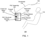
    • FIG. 1 is a side-view block diagram of an example environment for a passenger safety console assembly for a vehicle.
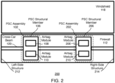
    • FIG. 2 is a front-view block diagram of an example environment for a passenger safety console assembly for a vehicle.
    • FIG. 3 is a flow chart for providing a passenger safety console assembly for a vehicle.
    DETAILED DESCRIPTION
  • FIG. 1 is a side-view block diagram of an example environment 100 for a passenger safety console (PSC) assembly 102 for a vehicle 104. The passenger safety console assembly 102 includes at least one PSC structural member 106. In various embodiments, the PSC structural assembly 102 also includes one or more airbag modules such as airbag module 108 and airbag module 110.
  • In various embodiments, the PSC structural member 106 is coupled to a body in white (BIW) portion of the vehicle104. The BIW portion may include the frame of the vehicle after assembly and before the motor, chassis sub-assemblies, and trim have been integrated into the vehicle 104. In various embodiments, the BIW portion of the vehicle may include a firewall 112. The firewall 112 separates the cabin or cab of the vehicle 104 from the engine compartment.
  • As shown, the PSC structural member 106 is coupled to the firewall 112. The firewall 112 may be a portion of the BIW of the vehicle, which is attached to or forms part of the chassis of the vehicle. Also, the PSC structural member 106 is positioned behind an instrument panel 114. In other implementations, environment 100 may not have all of the components shown and/or may have other elements including other types of elements instead of, or in addition to, those shown herein.
  • The PSC structural member 106 is adapted to couple to the airbag modules 108 and 110. In various embodiments, the PSC structural member 106 supports the airbag modules 108 and 110 when in stored states and when in deployed states during a collision. In various embodiments, the PSC structural member 106 is adapted to position the one or more airbag modules at predetermined angles. For example, the airbag module 108 is attached to the upper portion of the PSC structural member 106. As shown, the side of the PSC structural member 106 attached to the airbag module 108 is convex and angles the airbag module 108 upward at the predetermined angle toward the torso and head of an occupant 116 seated in the vehicle 102.
  • Due to the shape of the PSC structural member 106, the PSC structural member 106 is configured to conform around a cross-car beam 120. As shown, the PSC structural member 106 attaches to the firewall 112 above the cross-car beam 120 and angles downward and away from the firewall 112. The PSC structural member 106 conforms around the cross-car beam 120, and then angles toward the firewall 112. The PSC structural member 106 attaches to the firewall 112 at a second point below the cross-car beam 120.
  • In various embodiments, the distance of various portions of the PSC structural member 106 from the firewall 112 may vary, depending on the particular implementation. For example, as shown, the portion of the PSC structural member 106 that is furthest from the firewall 112 is approximately at the midpoint portion between the top and bottom of the PSC structural member 106. This particular shape enables the PSC structural member 106 bend or conform around the cross-car beam 120.
  • In various embodiments, the PSC structural member 106 may be shaped such that different portions of the PSC structural member 106 are positioned at different distances from the firewall 112. For example, either or both of the top and bottom portions of the PSC structural member 106 that couple to the respective airbag modules 108 and 110 are shown closer to the firewall 112 than the midpoint portion that bends over the cross-car beam 120. This shape shown creates an angle for the airbag module 108 and an angle for the airbag module 110. As described herein, the particular shape of the PSC structural member 106 may vary in order to control the angle of the airbag modules 108 and 110, and thereby control the trajectory of airbags associated with the airbag modules 108 and 110 as the airbags expand toward the occupant 116 during a collision.
  • Various shapes of the PSC structural member 106, and, in particular, the contour of the portions of the PSC structural member 106 that couple to the airbag modules 108 and 110 provide beneficial flexibility to the overall airbag system. For example, different shapes of the PSC structural member 106 enables each of the airbag modules 108 and 110 to be independently placed or positioned within the instrument panel 114 at predetermined angles. This in turn enables flexibility of the sizes of airbags and their positions. This is beneficial in autonomous or driverless vehicles where the seats in which the occupants are seated may be located further away from the instrument panel, where roominess is of high value. Having more roominess and possible positions of the seating for occupants introduces additional requirements with regard to deployment of the airbags. Embodiments described herein are sufficiently flexible to meet such requirements.
  • The shape and relative distances of the different portions of the PSC structural member 106 from the firewall 112 may vary, depending on the particular embodiment. For example, in some embodiments, the distance of that midpoint portion and the portions above and below the midpoint portion of the PSC structural member 106 may all extend further out and away from the firewall 112, past the cross-car beam, and closer to the occupant 116. In another embodiment, the portion above that midpoint portion and/or below the midpoint portion of the PSC structural member 106 may further out and away from the firewall 112, even further than the midpoint portion of the PSC structural member 106. Such a shape may enable the midpoint portion of the PSC structural member 106 to optionally rest against the cross-car beam 120 for added stability. These example embodiments enable the PSC assembly 102 to provide different placement positions and angles of the airbag modules 108 and 110 within the instrument panel. Such flexibility enables airbags associated with the airbag modules 108 and 110 to be different sizes with respect to their folded/undeployed states and/or their expanded/deployed states.
  • As shown, the occupant is facing forward toward the instrument panel 114. In various embodiments, during a collision, the airbag module 108 deploys and inflates an airbag (not shown). The airbag inflates such that it expands and passes through the instrument panel 114 and fills the space between the instrument panel 114 and the occupant 116. In various embodiments, the PSC structural member 106 angles the airbag module 108 such that when the airbag is deployed, the head and torso of the occupant 116 make contact with the airbag. The head and torso of the occupant 116 are absorbed into the airbag thereby protecting the occupant 116 from injury of a second collision within the vehicle 102 (e.g., a collision into the instrument panel 114 or into the windshield 118).
  • As shown, the airbag module 108 is attached to the upper portion of the PSC structural member 106. As shown, the convex shape of the PSC structural member 106 angles the airbag module 110 downward at the predetermined angle toward the knees and legs of the occupant 116 seated in the vehicle 102. As indicated above, the occupant is facing forward toward the instrument panel 114. An upper airbag associated with the airbag module 108 may be referred to as a passenger airbag (PAB). A lower airbag associated with the airbag module 110 may be referred to as a knee airbag (KnAB).
  • In various embodiments, during a collision, the airbag module 110 deploys and inflates an airbag (not shown). The airbag inflates such that it expands and passes through the instrument panel 114 and fills the space between the instrument panel 114 and the occupant 116. In various embodiments, the PSC structural member 106 angles the airbag module 110 such that when the airbag is deployed, the knees and legs of the occupant 116 make contact with the airbag. The knees and legs of the occupant 116 are absorbed into the airbag thereby protecting the occupant 116 from injury of a second collision within the vehicle 102 (e.g., a collision into the instrument panel 114).
  • The PSC structural member 106 may be a molded single piece. The PSC structural member 106 may be manufactured from any suitable rigid material. The type of material may vary, and will depend on the particular implementation. For example, in some embodiments, the PSC structural member 106 may be made of a metal, plastic, or composite material.
  • FIG. 2 is a front-view block diagram of an example environment 200 for the PSC assembly 102 for the vehicle 104. Also shown is a second PSC assembly 202. The PSC assembly 102 includes the PSC structural member 106, the airbag module 108, and the airbag module 110. The PSC assembly 202 also includes a PSC structural member 206, an airbag module 208, and an airbag module 210. In other implementations, environment 200 may not have all of the components shown and/or may have other elements including other types of elements instead of, or in addition to, those shown herein.
  • As shown, in various embodiments, the PSC structural member 106 and the PSC structural member 206 are adapted to couple to and hold/ support airbag modules 108, 110, 208, and 210, respectively. As described in more detail below, in the absence of a steering wheel, cross-car beam 120 is optional, and is not needed for the purpose of supporting airbag modules. The cross-car beam 120 may still be desired for other purposes such as providing additional integrity to the strength of chassis of the vehicle in the event of a collision. With a more limited use, the cross-car beam 120 may be designed to be much simpler without additional attachments required to support airbag modules. As such the cross-car beam 120 may be designed to be lighter in weight and more cost effective than conventional cross-car beams.
  • As shown, the cross-car beam 120 spans between a left-side structure 212 and a right-side structure 214 of the vehicle 104. The left-side structure 212 and the right-side structure 214 may be any side portions or BIW portions of the vehicle. For example, the left-side structure 212 and the right-side structure 214 may be A-pillars positioned on either side of the windshield 118 of a vehicle, which connects the floor structure and the roof to the vehicle.
  • As shown in FIG. 1, the PSC structural member 106 is configured with a shape that wraps around the cross-car beam 120. As described above, the PSC structural members are adapted to position the respective airbag modules at predetermined angles. Further example embodiments directed to the angling of airbag modules are described in more detail below.
  • As indicated above, a cross-car beam such as the cross-car beam 120 may be a complex vehicle component. This is because a conventional cross-car beam is designed to hold various types of vehicle components such as a steering wheel, airbags, an instrument panel, etc. Such cross-car beams may be expensive to design and manufacture. Also, cross-car beams add additional weight to vehicles, where excess weight is undesired in vehicles such as electric vehicles.
  • In various embodiments, the PSC structural member 106 and the PSC structural member 206 are used in lieu of a cross-bar beam, such as the cross-car beam 120. For example, these PSC structural members 106 and 206 couple to and hold respective airbag modules 108, 110, 208, and 210, rendering the cross-car beam 120 unneeded for the purpose of supporting airbag modules. In an autonomous or driverless vehicle, a steering wheel is optional and as such may not be present in a given vehicle. As such, the cross-car beam 120 is optional.
  • As indicated above, the PSC structural member 106 and the PSC structural member 206 attach to the firewall 112. In scenarios where a cross-car beam such as cross-car beam 120 is present, the PSC structural members 106 and 206 are configured such that they conform around the cross-car beam 120, as shown in FIG. 1. In scenarios where a cross-car beam 120 is not present, the PSC structural members 106 and 206 still attach to the firewall 112 in the same manner.
  • In various embodiments, the PSC structural member 106 spans a portion of the distance between the left-side structure 212 and the right-side structure 214 of the vehicle 104. In other words, the PSC structural member 106 does not span the entire distance between the left-side structure 212 and the right-side structure 214. Similarly, the PSC structural member 206 spans a portion of the distance between the left-side structure 212 and the right-side structure 214 of the vehicle 104, and also does not span the entire distance between the left-side structure 212 and the right-side structure 214. The size of the gap or distance between the PSC structural member 106 and the PSC structural member 206 may vary, and will depend on the particular implementation.
  • In various embodiments, the PSC structural member 106 and PSC structural member 206 are separated by a predetermined distance. The distance may vary based on the positions of the PSC structural members 106 and 206. In some embodiments, each of the PC structural members 106 and 206 are positioned on the firewall 112 such that they are positioned in front of passenger seats. For example, as described above in connection with FIG. 1, the PSC structural member 106 is positioned on the firewall 112 in front of the seat of the occupant 116 such that the airbags associated with airbag modules 108 and 110 deploy toward the occupant 116 in the event of a collision. Similarly, the PSC structural member 206 is positioned on the firewall 112 in front of a second seat of a second occupant (not shown) such that airbags associated with airbag modules 208 and 210 deploy toward the second occupant in the event of a collision.
  • In various embodiments, the PSC structural members 106 and 206 are configured to couple to one or more instruments in addition to coupling to the respective airbag modules 108, 110, 208, and 210. The instruments may vary, depending on the particular implementation. For example, instruments may include devices associated with entertainment for occupants of the vehicle 104, including media devices, display screens, etc. Instruments may also include devices associated with operations of the vehicle 104, including climate control devices, global positioning system (GPS) devices, speedometers, steering device, etc. The particular shape (e.g., contour, etc.) and size (e.g., width, height, etc.) of the PSC structural members 106 and 206 may vary, depending on the particular components to be attached to the PSC structural members 106 and 206. Also, the shape and size of the PSC structural members 106 and 206 may be different from or substantially identical to each other.
  • While various embodiments are described herein in the context of one or two PSC assemblies, the actual number of PSC assemblies employed in a given vehicle may vary, depending on the particular embodiment. For example, in some embodiments, there may be three or more PSC assemblies that are positioned behind the instrument panel 114. This may be for scenarios, for example, where there are three individual seats at the front of the cab or a bench seat at the front of the cab, where the bench seat seats three or more occupants.
  • Also, while various embodiments are described herein in the context of PSC assemblies positioned at the front of the cab of the vehicle, there may be similar PSC assemblies also positioned at the sides in the cab of the vehicle or behind one or more seats (e.g., front seats, etc.) to protect passengers seated in the rear of the vehicle. Without a need for a cross-car beam, such PSC assemblies may be flexibly deployed as needed in different locations in the cab to provide more airbag protection for occupants riding in the vehicle.
  • FIG. 3 is a flow chart for providing a passenger safety console assembly for a vehicle. Referring to both FIGS. 1, 2, and 3, a method is initiated at block 302, where one or more PSC structural members are adapted to be disposed or coupled to a body in white (BIW) portion of the vehicle 104. For example, as shown in FIGS. 1 and 2, the PSC structural members 106 and 206 are coupled to the firewall 112. As indicated above, the firewall 112 may be a portion of the BIW of the vehicle, which is attached to or forms part of the chassis of the vehicle.
  • In various embodiments, the one or more PSC structural members are positioned behind the instrument panel 114. As indicated above, each of the one or more PSC structural members spans a portion of the distance between side structures of the vehicle, such as the left-side structure 212 and the right-side structure 214.
  • At block 304, one or more airbag modules are adapted to be disposed or coupled to each of the respective PSC structural members 106 and 206. As indicated above, each of the PSC structural members 106 and 206 support one or more airbag modules when in stored states and when in deployed states during a collision.
  • As described above, in various embodiments, the PSC structural members 106 and 206 are adapted to position their respective airbag modules 108, 110, 208, and 210 at predetermined angles. In various embodiments, the PSC structural members 106 and 206 may function in lieu of the cross-car beam 120. In various embodiments, the PSC structural members 106 and 206 are configured to conform around the cross-car beam 120. In various embodiments, the PSC structural members 106 and 206 are separated by a predetermined distance. In various embodiments, the PSC structural members 106 and 206 are configured to couple to one or more instruments in addition to coupling to one or more airbag modules.
  • Although the steps, operations, or computations may be presented in a specific order, the order may be changed in particular implementations. Other orderings of the steps are possible, depending on the particular implementation. In some particular implementations, multiple steps shown as sequential in this specification may be performed at the same time. Also, some implementations may not have all of the steps shown and/or may have other steps instead of, or in addition to, those shown herein.
  • Embodiments described herein have numerous benefits. For example, embodiments of the PSC assembly and PSC structural members enable optimum positioning and angling of passenger and knee airbags towards occupants of a vehicle without any connection to a cross-car beam or instrument panel. This enables great freedom for instrument panel design and weight reduction potential for a vehicle, as a PSC structural member renders a cross-car beam optional. Embodiments optimize the positions of airbags toward occupants of vehicles. Embodiments also provide more flexibility as to the size and arrangements of airbags.
  • Although the present disclosure is illustrated and described herein with reference to illustrative embodiments and specific examples provided, it will be readily apparent to those of ordinary skill in the art that other embodiments and examples may perform similar functions and/or achieve like results. All such equivalent embodiments and examples are within the spirit and scope of the present disclosure and are intended to be covered by the following non-limiting claims for all purposes.
Claims (14)

  1. A passenger safety console assembly for a vehicle, the passenger safety console assembly comprising:
    at least one structural member coupled to a body in white portion of the vehicle, wherein the at least one structural member is positioned behind an instrument panel, and wherein the at least one structural member spans only a portion of a distance between side structures of the vehicle.
  2. The passenger safety assembly of claim 1, wherein the at least one structural member is adapted to couple to one or more airbag modules.
  3. The passenger safety assembly of any of the preceding claims, wherein the at least one structural member is adapted to position the one or more airbag modules at predetermined angles.
  4. The passenger safety assembly of any of the preceding claims, wherein the at least one structural member functions in lieu of a cross-car beam that spans an entire distance between side structures of the vehicle.
  5. The passenger safety assembly of any of the preceding claims, wherein the at least one structural member is configured to conform around a cross-car beam that spans an entire distance between side structures of the vehicle.
  6. The passenger safety assembly of any of the preceding claims, wherein the at least one structural member comprises a first structural member and a second structural member, wherein the first structural member and the second structural member are separated by a predetermined distance.
  7. The passenger safety assembly of any of the preceding claims, wherein the at least one structural member is configured to couple to one or more instruments in addition to coupling to one or more airbag modules.
  8. A passenger safety console assembly for a vehicle, the passenger safety console assembly comprising:
    at least one structural member coupled to a body in white portion of the vehicle, wherein the at least one structural member is positioned behind an instrument panel, and wherein the at least one structural member spans only a portion of a distance between side structures of the vehicle; and
    one or more airbag modules coupled to the at least one structural member, wherein the at least one structural member supports the one or more airbag modules when in stored states and when in deployed states during a collision.
  9. The passenger safety assembly of claim 8, wherein the at least one structural member is adapted to position the one or more airbag modules at predetermined angles.
  10. The passenger safety assembly of claim 8, wherein the at least one structural member functions in lieu of a cross-car beam that spans an entire distance between side structures of the vehicle.
  11. The passenger safety assembly of claim 8, wherein the at least one structural member is configured to conform around a cross-car beam that spans an entire distance between side structures of the vehicle.
  12. The passenger safety assembly of claim 8, wherein the at least one structural member comprises a first structural member and a second structural member, wherein the first structural member and the second structural member are separated by a predetermined distance.
  13. The passenger safety assembly of claim 8, wherein the at least one structural member is configured to couple to one or more instruments in addition to coupling to one or more airbag modules.
  14. A vehicle comprising:
    a body in white portion; and
    a passenger safety console assembly according to any of claims 1-13 coupled to the body in white portion.
EP24215680.0A 2023-12-21 2024-11-27 Passenger safety console assembly for a vehicle Pending EP4574631A1 (en)

Applications Claiming Priority (1)

Application Number Priority Date Filing Date Title
US18/392,029 US12434652B2 (en) 2023-12-21 2023-12-21 Passenger safety console assembly for a vehicle

Publications (1)

Publication Number Publication Date
EP4574631A1 true EP4574631A1 (en) 2025-06-25

Family

ID=93705113

Family Applications (1)

Application Number Title Priority Date Filing Date
EP24215680.0A Pending EP4574631A1 (en) 2023-12-21 2024-11-27 Passenger safety console assembly for a vehicle

Country Status (3)

Country Link
US (1) US12434652B2 (en)
EP (1) EP4574631A1 (en)
CN (1) CN120191443A (en)

Citations (3)

* Cited by examiner, † Cited by third party
Publication number Priority date Publication date Assignee Title
US5934733A (en) * 1997-12-19 1999-08-10 General Motors Corporation Extruded instrument panel structure
US20150291120A1 (en) * 2012-11-29 2015-10-15 Autoliv Development Ab Safety apparatus for vehicle
DE202016004512U1 (en) * 2016-07-20 2017-10-26 GM Global Technology Operations LLC (n. d. Ges. d. Staates Delaware) Dashboard assembly for a vehicle and vehicle with the dashboard assembly

Family Cites Families (5)

* Cited by examiner, † Cited by third party
Publication number Priority date Publication date Assignee Title
GB2332177A (en) * 1997-12-10 1999-06-16 Rover Group Deformable airbag module
US7841648B2 (en) * 2004-03-26 2010-11-30 Autotech Engineering A.I.E. Support crossbeam for an instrument panel
US8540274B2 (en) * 2011-12-22 2013-09-24 Nissan North America, Inc. Vehicle airbag support assembly
US9221418B1 (en) * 2014-07-14 2015-12-29 Ford Global Technologies, Llc Hinged mounting system for airbag module having deployable lock
US11351945B1 (en) * 2021-01-20 2022-06-07 Faurecia Interior Systems, Inc. Knee airbag cover

Patent Citations (3)

* Cited by examiner, † Cited by third party
Publication number Priority date Publication date Assignee Title
US5934733A (en) * 1997-12-19 1999-08-10 General Motors Corporation Extruded instrument panel structure
US20150291120A1 (en) * 2012-11-29 2015-10-15 Autoliv Development Ab Safety apparatus for vehicle
DE202016004512U1 (en) * 2016-07-20 2017-10-26 GM Global Technology Operations LLC (n. d. Ges. d. Staates Delaware) Dashboard assembly for a vehicle and vehicle with the dashboard assembly

Also Published As

Publication number Publication date
US12434652B2 (en) 2025-10-07
US20250206253A1 (en) 2025-06-26
CN120191443A (en) 2025-06-24

Similar Documents

Publication Publication Date Title
US11001221B2 (en) Passenger protection device for front passenger seat
US11279311B2 (en) Roof-mounted occupant restraint system
CN110893832B (en) Support for roof-mounted airbags
CN103010145B (en) Central curtain airbag apparatus for vehicle
US11479203B2 (en) Roof-mounted occupant restraint system
CN106853807B (en) Curtain airbag for vehicle
CN114126931A (en) Roof-mounted occupant restraint system
JP6575418B2 (en) Crew protection device
US8919886B2 (en) One-piece seat bottom chassis
US11214217B2 (en) Occupant restraint system
US8814201B2 (en) Knee airbag having increased package width
US20220126773A1 (en) Vehicle body structure
US20020195802A1 (en) Device for protecting the knees of vehicle occupants
EP3546299B1 (en) Knee-airbag-device attachment structure for a vehicle, a protection system, a vehicle, and a method of arranging a knee-airbag-device
CN117465377A (en) Instrument panel mounted knee airbag
US12434652B2 (en) Passenger safety console assembly for a vehicle
EP1772327A2 (en) Airbag system
JP2019172116A (en) Attachment structure of knee airbag device of vehicle
CN116788195A (en) Roof mounted airbag
US20230088807A1 (en) Airbag system for a vehicle
CN115303224A (en) Seat backrest type safety airbag
US20250153649A1 (en) Cross-vehicle beam forming a glove box that provides storage and accommodates load paths
US10399531B2 (en) Motor vehicle
JP7096996B2 (en) Mounting structure of vehicle knee airbag device
EP4046895B1 (en) Vehicle body structure

Legal Events

Date Code Title Description
PUAI Public reference made under article 153(3) epc to a published international application that has entered the european phase

Free format text: ORIGINAL CODE: 0009012

STAA Information on the status of an ep patent application or granted ep patent

Free format text: STATUS: THE APPLICATION HAS BEEN PUBLISHED

AK Designated contracting states

Kind code of ref document: A1

Designated state(s): AL AT BE BG CH CY CZ DE DK EE ES FI FR GB GR HR HU IE IS IT LI LT LU LV MC ME MK MT NL NO PL PT RO RS SE SI SK SM TR

STAA Information on the status of an ep patent application or granted ep patent

Free format text: STATUS: REQUEST FOR EXAMINATION WAS MADE

17P Request for examination filed

Effective date: 20260102