EP4574606A2 - Apparatus and method for processing vehicle signals to compute a behavioral hazard measure - Google Patents
Apparatus and method for processing vehicle signals to compute a behavioral hazard measure Download PDFInfo
- Publication number
- EP4574606A2 EP4574606A2 EP25174962.8A EP25174962A EP4574606A2 EP 4574606 A2 EP4574606 A2 EP 4574606A2 EP 25174962 A EP25174962 A EP 25174962A EP 4574606 A2 EP4574606 A2 EP 4574606A2
- Authority
- EP
- European Patent Office
- Prior art keywords
- traffic object
- vehicle
- hazard
- measure
- relative speed
- Prior art date
- Legal status (The legal status is an assumption and is not a legal conclusion. Google has not performed a legal analysis and makes no representation as to the accuracy of the status listed.)
- Pending
Links
Images


Classifications
-
- B—PERFORMING OPERATIONS; TRANSPORTING
- B60—VEHICLES IN GENERAL
- B60W—CONJOINT CONTROL OF VEHICLE SUB-UNITS OF DIFFERENT TYPE OR DIFFERENT FUNCTION; CONTROL SYSTEMS SPECIALLY ADAPTED FOR HYBRID VEHICLES; ROAD VEHICLE DRIVE CONTROL SYSTEMS FOR PURPOSES NOT RELATED TO THE CONTROL OF A PARTICULAR SUB-UNIT
- B60W30/00—Purposes of road vehicle drive control systems not related to the control of a particular sub-unit, e.g. of systems using conjoint control of vehicle sub-units
- B60W30/08—Active safety systems predicting or avoiding probable or impending collision or attempting to minimise its consequences
- B60W30/095—Predicting travel path or likelihood of collision
- B60W30/0956—Predicting travel path or likelihood of collision the prediction being responsive to traffic or environmental parameters
-
- B—PERFORMING OPERATIONS; TRANSPORTING
- B60—VEHICLES IN GENERAL
- B60W—CONJOINT CONTROL OF VEHICLE SUB-UNITS OF DIFFERENT TYPE OR DIFFERENT FUNCTION; CONTROL SYSTEMS SPECIALLY ADAPTED FOR HYBRID VEHICLES; ROAD VEHICLE DRIVE CONTROL SYSTEMS FOR PURPOSES NOT RELATED TO THE CONTROL OF A PARTICULAR SUB-UNIT
- B60W30/00—Purposes of road vehicle drive control systems not related to the control of a particular sub-unit, e.g. of systems using conjoint control of vehicle sub-units
- B60W30/08—Active safety systems predicting or avoiding probable or impending collision or attempting to minimise its consequences
- B60W30/09—Taking automatic action to avoid collision, e.g. braking and steering
-
- B—PERFORMING OPERATIONS; TRANSPORTING
- B60—VEHICLES IN GENERAL
- B60W—CONJOINT CONTROL OF VEHICLE SUB-UNITS OF DIFFERENT TYPE OR DIFFERENT FUNCTION; CONTROL SYSTEMS SPECIALLY ADAPTED FOR HYBRID VEHICLES; ROAD VEHICLE DRIVE CONTROL SYSTEMS FOR PURPOSES NOT RELATED TO THE CONTROL OF A PARTICULAR SUB-UNIT
- B60W30/00—Purposes of road vehicle drive control systems not related to the control of a particular sub-unit, e.g. of systems using conjoint control of vehicle sub-units
- B60W30/08—Active safety systems predicting or avoiding probable or impending collision or attempting to minimise its consequences
- B60W30/095—Predicting travel path or likelihood of collision
- B60W30/0953—Predicting travel path or likelihood of collision the prediction being responsive to vehicle dynamic parameters
-
- B—PERFORMING OPERATIONS; TRANSPORTING
- B60—VEHICLES IN GENERAL
- B60W—CONJOINT CONTROL OF VEHICLE SUB-UNITS OF DIFFERENT TYPE OR DIFFERENT FUNCTION; CONTROL SYSTEMS SPECIALLY ADAPTED FOR HYBRID VEHICLES; ROAD VEHICLE DRIVE CONTROL SYSTEMS FOR PURPOSES NOT RELATED TO THE CONTROL OF A PARTICULAR SUB-UNIT
- B60W30/00—Purposes of road vehicle drive control systems not related to the control of a particular sub-unit, e.g. of systems using conjoint control of vehicle sub-units
- B60W30/14—Adaptive cruise control
- B60W30/16—Control of distance between vehicles, e.g. keeping a distance to preceding vehicle
- B60W30/162—Speed limiting therefor
-
- B—PERFORMING OPERATIONS; TRANSPORTING
- B60—VEHICLES IN GENERAL
- B60W—CONJOINT CONTROL OF VEHICLE SUB-UNITS OF DIFFERENT TYPE OR DIFFERENT FUNCTION; CONTROL SYSTEMS SPECIALLY ADAPTED FOR HYBRID VEHICLES; ROAD VEHICLE DRIVE CONTROL SYSTEMS FOR PURPOSES NOT RELATED TO THE CONTROL OF A PARTICULAR SUB-UNIT
- B60W30/00—Purposes of road vehicle drive control systems not related to the control of a particular sub-unit, e.g. of systems using conjoint control of vehicle sub-units
- B60W30/18—Propelling the vehicle
- B60W30/18009—Propelling the vehicle related to particular drive situations
- B60W30/18163—Lane change; Overtaking manoeuvres
-
- B—PERFORMING OPERATIONS; TRANSPORTING
- B60—VEHICLES IN GENERAL
- B60W—CONJOINT CONTROL OF VEHICLE SUB-UNITS OF DIFFERENT TYPE OR DIFFERENT FUNCTION; CONTROL SYSTEMS SPECIALLY ADAPTED FOR HYBRID VEHICLES; ROAD VEHICLE DRIVE CONTROL SYSTEMS FOR PURPOSES NOT RELATED TO THE CONTROL OF A PARTICULAR SUB-UNIT
- B60W40/00—Estimation or calculation of non-directly measurable driving parameters for road vehicle drive control systems not related to the control of a particular sub unit, e.g. by using mathematical models
- B60W40/02—Estimation or calculation of non-directly measurable driving parameters for road vehicle drive control systems not related to the control of a particular sub unit, e.g. by using mathematical models related to ambient conditions
- B60W40/06—Road conditions
- B60W40/064—Degree of grip
-
- G—PHYSICS
- G08—SIGNALLING
- G08G—TRAFFIC CONTROL SYSTEMS
- G08G1/00—Traffic control systems for road vehicles
- G08G1/01—Detecting movement of traffic to be counted or controlled
- G08G1/0104—Measuring and analyzing of parameters relative to traffic conditions
- G08G1/0108—Measuring and analyzing of parameters relative to traffic conditions based on the source of data
- G08G1/0112—Measuring and analyzing of parameters relative to traffic conditions based on the source of data from the vehicle, e.g. floating car data [FCD]
-
- G—PHYSICS
- G08—SIGNALLING
- G08G—TRAFFIC CONTROL SYSTEMS
- G08G1/00—Traffic control systems for road vehicles
- G08G1/01—Detecting movement of traffic to be counted or controlled
- G08G1/0104—Measuring and analyzing of parameters relative to traffic conditions
- G08G1/0108—Measuring and analyzing of parameters relative to traffic conditions based on the source of data
- G08G1/0116—Measuring and analyzing of parameters relative to traffic conditions based on the source of data from roadside infrastructure, e.g. beacons
-
- G—PHYSICS
- G08—SIGNALLING
- G08G—TRAFFIC CONTROL SYSTEMS
- G08G1/00—Traffic control systems for road vehicles
- G08G1/01—Detecting movement of traffic to be counted or controlled
- G08G1/0104—Measuring and analyzing of parameters relative to traffic conditions
- G08G1/0125—Traffic data processing
- G08G1/0129—Traffic data processing for creating historical data or processing based on historical data
-
- G—PHYSICS
- G08—SIGNALLING
- G08G—TRAFFIC CONTROL SYSTEMS
- G08G1/00—Traffic control systems for road vehicles
- G08G1/01—Detecting movement of traffic to be counted or controlled
- G08G1/0104—Measuring and analyzing of parameters relative to traffic conditions
- G08G1/0125—Traffic data processing
- G08G1/0133—Traffic data processing for classifying traffic situation
-
- G—PHYSICS
- G08—SIGNALLING
- G08G—TRAFFIC CONTROL SYSTEMS
- G08G1/00—Traffic control systems for road vehicles
- G08G1/01—Detecting movement of traffic to be counted or controlled
- G08G1/0104—Measuring and analyzing of parameters relative to traffic conditions
- G08G1/0137—Measuring and analyzing of parameters relative to traffic conditions for specific applications
- G08G1/0141—Measuring and analyzing of parameters relative to traffic conditions for specific applications for traffic information dissemination
-
- G—PHYSICS
- G08—SIGNALLING
- G08G—TRAFFIC CONTROL SYSTEMS
- G08G1/00—Traffic control systems for road vehicles
- G08G1/01—Detecting movement of traffic to be counted or controlled
- G08G1/0104—Measuring and analyzing of parameters relative to traffic conditions
- G08G1/0137—Measuring and analyzing of parameters relative to traffic conditions for specific applications
- G08G1/0145—Measuring and analyzing of parameters relative to traffic conditions for specific applications for active traffic flow control
-
- G—PHYSICS
- G08—SIGNALLING
- G08G—TRAFFIC CONTROL SYSTEMS
- G08G1/00—Traffic control systems for road vehicles
- G08G1/16—Anti-collision systems
- G08G1/164—Centralised systems, e.g. external to vehicles
-
- G—PHYSICS
- G08—SIGNALLING
- G08G—TRAFFIC CONTROL SYSTEMS
- G08G1/00—Traffic control systems for road vehicles
- G08G1/16—Anti-collision systems
- G08G1/166—Anti-collision systems for active traffic, e.g. moving vehicles, pedestrians, bikes
-
- B—PERFORMING OPERATIONS; TRANSPORTING
- B60—VEHICLES IN GENERAL
- B60W—CONJOINT CONTROL OF VEHICLE SUB-UNITS OF DIFFERENT TYPE OR DIFFERENT FUNCTION; CONTROL SYSTEMS SPECIALLY ADAPTED FOR HYBRID VEHICLES; ROAD VEHICLE DRIVE CONTROL SYSTEMS FOR PURPOSES NOT RELATED TO THE CONTROL OF A PARTICULAR SUB-UNIT
- B60W2520/00—Input parameters relating to overall vehicle dynamics
- B60W2520/10—Longitudinal speed
- B60W2520/105—Longitudinal acceleration
-
- B—PERFORMING OPERATIONS; TRANSPORTING
- B60—VEHICLES IN GENERAL
- B60W—CONJOINT CONTROL OF VEHICLE SUB-UNITS OF DIFFERENT TYPE OR DIFFERENT FUNCTION; CONTROL SYSTEMS SPECIALLY ADAPTED FOR HYBRID VEHICLES; ROAD VEHICLE DRIVE CONTROL SYSTEMS FOR PURPOSES NOT RELATED TO THE CONTROL OF A PARTICULAR SUB-UNIT
- B60W2540/00—Input parameters relating to occupants
- B60W2540/10—Accelerator pedal position
-
- B—PERFORMING OPERATIONS; TRANSPORTING
- B60—VEHICLES IN GENERAL
- B60W—CONJOINT CONTROL OF VEHICLE SUB-UNITS OF DIFFERENT TYPE OR DIFFERENT FUNCTION; CONTROL SYSTEMS SPECIALLY ADAPTED FOR HYBRID VEHICLES; ROAD VEHICLE DRIVE CONTROL SYSTEMS FOR PURPOSES NOT RELATED TO THE CONTROL OF A PARTICULAR SUB-UNIT
- B60W2540/00—Input parameters relating to occupants
- B60W2540/12—Brake pedal position
-
- B—PERFORMING OPERATIONS; TRANSPORTING
- B60—VEHICLES IN GENERAL
- B60W—CONJOINT CONTROL OF VEHICLE SUB-UNITS OF DIFFERENT TYPE OR DIFFERENT FUNCTION; CONTROL SYSTEMS SPECIALLY ADAPTED FOR HYBRID VEHICLES; ROAD VEHICLE DRIVE CONTROL SYSTEMS FOR PURPOSES NOT RELATED TO THE CONTROL OF A PARTICULAR SUB-UNIT
- B60W2540/00—Input parameters relating to occupants
- B60W2540/18—Steering angle
-
- B—PERFORMING OPERATIONS; TRANSPORTING
- B60—VEHICLES IN GENERAL
- B60W—CONJOINT CONTROL OF VEHICLE SUB-UNITS OF DIFFERENT TYPE OR DIFFERENT FUNCTION; CONTROL SYSTEMS SPECIALLY ADAPTED FOR HYBRID VEHICLES; ROAD VEHICLE DRIVE CONTROL SYSTEMS FOR PURPOSES NOT RELATED TO THE CONTROL OF A PARTICULAR SUB-UNIT
- B60W2552/00—Input parameters relating to infrastructure
- B60W2552/40—Coefficient of friction
-
- B—PERFORMING OPERATIONS; TRANSPORTING
- B60—VEHICLES IN GENERAL
- B60W—CONJOINT CONTROL OF VEHICLE SUB-UNITS OF DIFFERENT TYPE OR DIFFERENT FUNCTION; CONTROL SYSTEMS SPECIALLY ADAPTED FOR HYBRID VEHICLES; ROAD VEHICLE DRIVE CONTROL SYSTEMS FOR PURPOSES NOT RELATED TO THE CONTROL OF A PARTICULAR SUB-UNIT
- B60W2554/00—Input parameters relating to objects
- B60W2554/40—Dynamic objects, e.g. animals, windblown objects
- B60W2554/404—Characteristics
- B60W2554/4041—Position
-
- B—PERFORMING OPERATIONS; TRANSPORTING
- B60—VEHICLES IN GENERAL
- B60W—CONJOINT CONTROL OF VEHICLE SUB-UNITS OF DIFFERENT TYPE OR DIFFERENT FUNCTION; CONTROL SYSTEMS SPECIALLY ADAPTED FOR HYBRID VEHICLES; ROAD VEHICLE DRIVE CONTROL SYSTEMS FOR PURPOSES NOT RELATED TO THE CONTROL OF A PARTICULAR SUB-UNIT
- B60W2554/00—Input parameters relating to objects
- B60W2554/40—Dynamic objects, e.g. animals, windblown objects
- B60W2554/404—Characteristics
- B60W2554/4042—Longitudinal speed
-
- B—PERFORMING OPERATIONS; TRANSPORTING
- B60—VEHICLES IN GENERAL
- B60W—CONJOINT CONTROL OF VEHICLE SUB-UNITS OF DIFFERENT TYPE OR DIFFERENT FUNCTION; CONTROL SYSTEMS SPECIALLY ADAPTED FOR HYBRID VEHICLES; ROAD VEHICLE DRIVE CONTROL SYSTEMS FOR PURPOSES NOT RELATED TO THE CONTROL OF A PARTICULAR SUB-UNIT
- B60W2554/00—Input parameters relating to objects
- B60W2554/40—Dynamic objects, e.g. animals, windblown objects
- B60W2554/404—Characteristics
- B60W2554/4044—Direction of movement, e.g. backwards
-
- B—PERFORMING OPERATIONS; TRANSPORTING
- B60—VEHICLES IN GENERAL
- B60W—CONJOINT CONTROL OF VEHICLE SUB-UNITS OF DIFFERENT TYPE OR DIFFERENT FUNCTION; CONTROL SYSTEMS SPECIALLY ADAPTED FOR HYBRID VEHICLES; ROAD VEHICLE DRIVE CONTROL SYSTEMS FOR PURPOSES NOT RELATED TO THE CONTROL OF A PARTICULAR SUB-UNIT
- B60W2554/00—Input parameters relating to objects
- B60W2554/40—Dynamic objects, e.g. animals, windblown objects
- B60W2554/404—Characteristics
- B60W2554/4049—Relationship among other objects, e.g. converging dynamic objects
-
- B—PERFORMING OPERATIONS; TRANSPORTING
- B60—VEHICLES IN GENERAL
- B60W—CONJOINT CONTROL OF VEHICLE SUB-UNITS OF DIFFERENT TYPE OR DIFFERENT FUNCTION; CONTROL SYSTEMS SPECIALLY ADAPTED FOR HYBRID VEHICLES; ROAD VEHICLE DRIVE CONTROL SYSTEMS FOR PURPOSES NOT RELATED TO THE CONTROL OF A PARTICULAR SUB-UNIT
- B60W2554/00—Input parameters relating to objects
- B60W2554/80—Spatial relation or speed relative to objects
- B60W2554/801—Lateral distance
-
- B—PERFORMING OPERATIONS; TRANSPORTING
- B60—VEHICLES IN GENERAL
- B60W—CONJOINT CONTROL OF VEHICLE SUB-UNITS OF DIFFERENT TYPE OR DIFFERENT FUNCTION; CONTROL SYSTEMS SPECIALLY ADAPTED FOR HYBRID VEHICLES; ROAD VEHICLE DRIVE CONTROL SYSTEMS FOR PURPOSES NOT RELATED TO THE CONTROL OF A PARTICULAR SUB-UNIT
- B60W2554/00—Input parameters relating to objects
- B60W2554/80—Spatial relation or speed relative to objects
- B60W2554/802—Longitudinal distance
-
- B—PERFORMING OPERATIONS; TRANSPORTING
- B60—VEHICLES IN GENERAL
- B60W—CONJOINT CONTROL OF VEHICLE SUB-UNITS OF DIFFERENT TYPE OR DIFFERENT FUNCTION; CONTROL SYSTEMS SPECIALLY ADAPTED FOR HYBRID VEHICLES; ROAD VEHICLE DRIVE CONTROL SYSTEMS FOR PURPOSES NOT RELATED TO THE CONTROL OF A PARTICULAR SUB-UNIT
- B60W2554/00—Input parameters relating to objects
- B60W2554/80—Spatial relation or speed relative to objects
- B60W2554/803—Relative lateral speed
-
- B—PERFORMING OPERATIONS; TRANSPORTING
- B60—VEHICLES IN GENERAL
- B60W—CONJOINT CONTROL OF VEHICLE SUB-UNITS OF DIFFERENT TYPE OR DIFFERENT FUNCTION; CONTROL SYSTEMS SPECIALLY ADAPTED FOR HYBRID VEHICLES; ROAD VEHICLE DRIVE CONTROL SYSTEMS FOR PURPOSES NOT RELATED TO THE CONTROL OF A PARTICULAR SUB-UNIT
- B60W2554/00—Input parameters relating to objects
- B60W2554/80—Spatial relation or speed relative to objects
- B60W2554/804—Relative longitudinal speed
-
- B—PERFORMING OPERATIONS; TRANSPORTING
- B60—VEHICLES IN GENERAL
- B60W—CONJOINT CONTROL OF VEHICLE SUB-UNITS OF DIFFERENT TYPE OR DIFFERENT FUNCTION; CONTROL SYSTEMS SPECIALLY ADAPTED FOR HYBRID VEHICLES; ROAD VEHICLE DRIVE CONTROL SYSTEMS FOR PURPOSES NOT RELATED TO THE CONTROL OF A PARTICULAR SUB-UNIT
- B60W2556/00—Input parameters relating to data
- B60W2556/10—Historical data
Definitions
- This invention relates generally to measuring the safety of the operation of vehicles. More particularly, this invention is directed toward techniques for processing sensor signals to compute a behavioral hazard measure characterizing near-miss behaviors to assess safety.
- the current practice to measure the safety of the behavior and control of a vehicle is on the basis of the frequency of occurrence of collisions. In some cases, a measure of time-to-collision is used.
- the number of disengagements of an onboard automated decision-making system per mile (where a disengagement is a manual override of the automated system, such as described in California, California Code of Regulations, Title 13, Div. 1, Ch. 1, Article 3.8, ⁇ 227.501) is also used as an indication of the performance and safety of the behavior of an automated or autonomous vehicle.
- collision occurrences are relatively infrequent, and many collisions occur as a result of multiple causes. As a result, collision occurrence data is not able to provide a repeatable, computable nearly continuous measure of the safety and risk of the behavior of a subject vehicle.
- Time-to-collision is dependent on the street or road conditions and on the speed and maneuverability of each object in each traffic scenario. As a result, time-to-collision is not independent of road conditions nor speed nor capabilities of the subject vehicle and traffic objects, and as a result cannot be used as an independent, computable, nearly continuous measure of the safety and risk of the behavior of a subject vehicle.
- the number of “disengagements” per mile is not a useful measure of the behavior or safety or risk of an automated vehicle. “Disengagements” can have many causes, which may not be related to the behavior or decision-making system of the vehicle. They are not repeat- able, are subject to the judgment of the safety driver and therefore occur due to subjective considerations and as a result are not objective, and are influenced by the selection of the conditions and scenarios under which the vehicle is operated and the operational policy or policies under which the driver operates.
- Loss of separation incorporates no information on the speeds (relative nor absolute) of the vehicle an object and therefore is not able to indicate important characteristics of the severity of a near-miss.
- a non-transitory computer readable storage medium has instructions executed by a processor to obtain the relative speed between a first traffic object and a second traffic object. The separation distance between the first traffic object and the second traffic object is received. The relative speed and the separation distance are combined to form a quantitative measure of hazard encountered by the first traffic object. The obtain, receive and combine operations are repeated to form cumulative measures of hazard associated with the first traffic object. The cumulative measures of hazard are analyzed to derive a first traffic object safety score for the first traffic object.
- This invention provides a method to quantitatively determine the safety and risk of an automated vehicle. Unlike existing assessments of vehicle safety that pertain to the ability of the subject vehicle to protect its occupants after a collision begins, this measure assesses the performance of vehicles prior to and entirely without reference to collisions. Collision data is customarily gathered and assessed as a frequency of occurrence. Collisions among existing passenger vehicles are relatively infrequent, limiting the analytic and predictive power of collision occurrence data.
- the new measure disclosed here gathers movement data about vehicles continuously and a quantitative score reflecting the riskiness or safeness of the behavior of vehicles is computed nearly continuously, limited only by the rate at which the sensors provide updated measurements of the positions and velocities of vehicles and road conditions.
- the new measure disclosed here is based on the concept of near-misses, rather than collisions.
- a near-miss a subject vehicle passes other traffic objects (e.g., vehicles, pedestrians, bicyclists, any moving object in a traffic scenario) but does not collide.
- the new measure is based, in part, on the proximity of the vehicle to each traffic object and the relative speed between the vehicle and each traffic object. In this way, the new measure can assess how near a vehicle is to a collision with another traffic object, and the relative speed. A small distance and low speed can be equivalent to a higher speed at a larger distance.
- an aggregation of the data into a score is performed.
- One such aggregation results in a triplet of scalars representing the behavior of a vehicle: the largest score during a time-period of interest; the percent of time that the score is above an unsafe threshold; the percent of time that the score is above a risky threshold. While these three scalar numbers do not fully capture the behavior of a vehicle in a complex traffic scenario, they capture representative characteristics that can be compared.
- the new measure can be used for evaluation of the performance of an automated vehicle, in particular the performance of the sensors on the vehicle, the configuration of the sensors on the vehicle, and the decision-making performed by the vehicle.
- the measure is intended to be applied to automated vehicles, it can equally be used to provide a score for human drivers (and, in-effect, their sensing, perception, and decision- making).
- the measure can be computed from vehicle and traffic object data (positions and velocities) that are generated by sensors onboard one or more vehicles, either moving or stationary, or generated by stationary sensors, such as video cameras used for traffic management.
- vehicle and traffic object data positions and velocities
- stationary sensors such as video cameras used for traffic management.
- Some drivers make less safe decisions than others; however, the infrequency of collisions, and the many contributing factors beyond driver decision-making to the occurrence of collisions, render this information of limited use to evaluate driver performance, or to judge whether a driver or operator (automated or human) is sufficiently safe to drive, particularly in congested and complex scenarios.
- TTC time-to- collision
- the novel measure of vehicle and traffic risk and safety described here utilizes the position and velocity of the subject vehicle, the position and velocity of each traffic object, the road conditions, and the maneuverability of the subject vehicle and traffic objects (maximum safe braking deceleration rate and maximum safe turning rate).
- the measure is computed sequentially for the subject vehicle in relation to each traffic object. For example, for a subject vehicle and eight (8) traffic objects, the measure will be computed in a pair-wise manner: eight (8) times at each time at which sensor data is available, once for each traffic object in relation to the subject vehicle.
- Measure (noun) an amount (of something) ascertained by measuring. The value of a measure is expressed in established or standardized units. A measure is a standard of comparison.
- Measure (verb) to ascertain the amount or degree of (something) by using signals resulting from measurements, usually by comparison with a standard.
- Hazard A source or circumstance of potential damage or harm to an object or a person.
- Risk The chance or probability that an object or a person will be damaged or harmed if exposed to a hazard.
- Subject Vehicle is the vehicle analyzed for behavior, safety and risk.
- Traffic Objects are other vehicles, pedestrians, bicyclists, and other moving objects in a traffic scenario. In any particular traffic scenario or situation there will be N traffic objects (in addition to the subject vehicle). Each traffic object is identified by a number from 1 to N.
- Traffic Scenario is a physical arrangement of roads and/or streets including traffic controls, street markings, curbs, crosswalks, and traffic objects.
- a typical traffic scenario may last 15-30 seconds, but may be shorter or longer in duration.
- Near-Miss is a circumstance where the subject vehicle moves at some distance from a traffic object at some speed in relation to the traffic object, but a collision does not occur.
- Position p is the vector position of the subject vehicle ( p v ) and each traffic object ( p 0 i ).
- Grip is the maximum safe acceleration that the subject vehicle or traffic objects can exhibit.
- the invention uses both braking grip (maximum safe acceleration or deceleration in the longitudinal direction) and lateral grip (maximum safe change of direction or acceleration or deceleration in the lateral direction) to incorporate the different capabilities of the subject vehicle or traffic objects to brake, steer, or change direction.
- grip is adjusted to account for road or street conditions, e.g., grip will be reduced by slippery road or street conditions.
- the value of grip is a measure of maneuverability of the subject vehicle and traffic objects.
- Acceleration is the rate of change of speed (expressed in units of distance divided by time squared, e.g., feet per second squared or feet per second per second, meters per second squared or meters per second per second). Acceleration can be either in the direction of travel (i.e., due to braking: braking deceleration) or transverse to the direction of travel (i.e., due to steering: lateral acceleration).
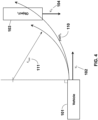
- Figure 1 shows an overhead view of the Subject Vehicle 101 moving with velocity ⁇ v 102 and Traffic Object i 103 moving with velocity v 0 i 104.
- the Subject Vehicle 101 and Traffic Object i 103 are approaching each other at an intersection of two streets, not shown.
- Separation Distance ( d sep ) 105 between the Subject Vehicle 101 and Traffic Object i 103 is shown.
- Relative Speed ( S rel ) is between the Subject Vehicle 101 moving with velocity ⁇ v 102 and Traffic Object i 103 moving with velocity v 0 i 104.
- Relative Speed ( S rel ) is computed from speed ( S v ) 106 of the Subject Vehicle 101 along the direction of the Separation Distance ( d sep ) 105 minus the speed ( S 0 i ) 107 of the Traffic Object i 103 along the direction of the Separation Distance ( d sep ) 105.
- Figure 2 shows an overhead view of the Relative Speed ( S rel ) 108 between the Subject Vehicle 101 moving with velocity ⁇ v 102 and Traffic Object i 103 moving with velocity v 0 i 104.
- Figure 3 shows an overhead view of the Radius r t 109 of curved path path v 110 required (with the relative positions shown in the figure) for the Subject Vehicle 101 to collide with the Traffic Object i 103.
- Figure 4 shows an overhead view of the Radius r t min 111 of sharpest turn possible without exceeding a lateral acceleration of grip.
- Figure 5 shows a graph of m 4 120 extending to large negative values and m 5 121 smoothly limited by the saturation computation of Equation (24) to the range 0 to -100.
- Figure 6 shows a block diagram of a test and evaluation of the safety of a vehicle operator 130. Data from onboard sensors 131 and/or offboard sensors 132 are utilized to compute the hazard measure of the invention.
- Figure 7 shows a block diagram of a test and evaluation of the safety of an automated or autonomous vehicle sensing 141 and decision-making 140 system. Data from onboard sensors 141 and/or offboard sensors 132 are utilized to compute the hazard measure of the invention.
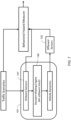
- Figure 8 shows a block diagram 200 of the data flow and data processing to compute the values of the hazard measure for data gathered from different sensors 141, such as cameras 201, Global Positioning System (GPS) 202, Lidar 205, and radar 206 onboard one or more vehicles, or offboard sensors 132.
- a synchronized data capture module 210 collects the sensor data and data extraction module 211 produces images and positions of traffic objects 212.
- training data 214 may be used for object detection 216 and object recognition 218.
- Object geometry 220 is then derived to produce geometric and kinematic data 222, e.g., position, size and speed data. This data is used in a hazard measure computation module 224, from which a hazard measure 226 is derived.
- Individual measures are aggregated in a hazard measure aggregation module 228, from which aggregated near-miss hazard measures 230 are derived.
- FIG. 9 illustrates a system 500 configured in accordance with an embodiment of the invention.
- the system 500 includes a first server 502 in communication with a second server 504 via a network 506, which may be any combination of wired and wireless networks.
- the first server 502 includes a processor (e.g., central processing unit or CPU) 510 connected to input/output devices 512 via a bus 514.
- the input/output devices 512 may be a proximate or remote keyboard, mouse, touch display and the like.
- a network interface circuit or NIC 516 is also connected to the bus 514 to provide connectivity to network 506.
- a memory 520 is also connected to the bus 514.
- the memory 520 stores transit data 522.
- the transit data 522 may be from sensors and other parameters collected from a Subject Vehicle 101 and different Traffic Objects 103 1 through 103 N , which may also be connected to the network 506.
- the transit data 522 may comprise an enormous collection of data from real world vehicles under test.
- the transit data 522 may also include data from traffic simulations, cameras recording traffic conditions for a defined regions, such as roads, intersections, highways and the like.
- the transit data may also include weather information, visibility conditions, current traffic conditions, historical traffic conditions, current angular sun measures, historical traffic risk data, historical loss data, aggregated traffic object data, and the like. It should be appreciated that the transit data 522 may be distributed across many machines (not shown) connected to network 506.
- the transit data 522 is shown on a single machine for convenience.
- Server 504 includes a processor 530, input/output devices 532, bus 534 and network interface circuit 536.
- a memory 540 is connected to bus 534.
- the memory 540 stores a behavioral hazard measure module 542, which includes instructions executed by processor 530 to implement the operations disclosed herein.
- the behavioral hazard measure module 542 may collect data from a Subject Vehicle 101 and Traffic Objects 103 1 through 103 N and the transit data 522 to perform the operations disclosed herein.
- a client machine 560 may also be connected to network 506.
- the client machine 560 includes a processor 561, input/output devices 562, a bus 564 and a network interface circuit 566 to provide connectivity to network 506.
- a memory 570 is connected to bus 564.
- the memory 570 stores a visualization module 572 with instructions executed by processor 561 to display visualizations of data generated by the behavioral hazard measure module 542.
- a first embodiment of the invention (hereinafter referred to as "mi") is the computation of the relative speed between the subject vehicle and a traffic object ( S rel ) divided by the distance that separates the vehicle and the object ( d sep ) .
- S rel ) and d sep are illustrated in the diagrams in Figures 1 and 2 , and shown in Equation (8):
- a second embodiment of the invention incorporates the maximum of the absolute speed of the subject vehicle ( S abs ) and the relative speed between the subject vehicle and a traffic object ( S rel ) divided by the distance that separates the vehicle and the object ( d sep ) , shown in Equation (9): m 2 has the units of [1/time].
- the invention maintains the sign convention established by m 1 in that the value of m 3 is negative when the subject vehicle and a traffic object are approaching each other (i.e., the relative speed between them is negative).
- the opposite sign convention i.e., m 3 is positive when the subject vehicle and a traffic object are approaching each other, is within the scope of the invention.
- m 4 accounts for consideration of the following: if the subject vehicle and the traffic object were to collide, what lateral acceleration (steering or change or direction) would be required to do so? m 4 reduces m 3 by the portion of grip that would be required to steer to cause a collision.
- h is the largest (negative) value of m 5 , typically 100.
- m 5 ranges continuously from 0 to -h.
- sat is the level of m 4 at which m 5 saturates (or is limited).
- ⁇ is a parameter to adjust the curvature of the transition from m 3 to the saturation level.
- the invention maintains the sign convention established by m 1 and maintained by m 3 and m 4 in that the value of m 5 is negative when the subject vehicle and a traffic object are approaching each other (i.e., the relative speed between them is negative).
- the opposite sign convention i.e., m 5 is positive when the subject vehicle and a traffic object are approaching each other, is within the scope of the invention.
- the embodiments of the invention described above can be augmented by incorporating the perception-reaction time (PRT) of the driver or controller of the vehicle.
- PRT perception-reaction time
- Typical human driver PRTs are around 1.5 seconds, and range from 750 milliseconds to over 3.5 seconds. There is little published data on automated or autonomous vehicle PRTs, but the published data suggests that they are between 11 and 200 milliseconds.
- a further embodiment of the invention incorporates PRT is by estimating the distance that the vehicle will travel during the PRT, assuming no change in direction or speed for the duration of the PRT, shown in Equation (25): where t reaction is the PRT of the controller or operator of the vehicle.
- Equation (26) The addition of PRT is accomplished by reducing d sep by d reaction . Therefore m 6 is a revision of m 5 where the basis of the computation of m 6 is shown in Equation (26):
- Equation (27) The value of d sep - d reaction is limited to be greater than or equal to zero, as shown in Equation (27):
- m 6 incorporates the square of the maximum of the absolute speed of the subject vehicle ( S abs ) and the relative speed between the subject vehicle and a traffic object ( S rel ) divided by the distance that separates the vehicle and the object ( d sep ), shown in Equation (28): m 6 has the units of length/time 2 or [acceleration].
- the influence of the speed of the subject vehicle in relation to the traffic object is considerably magnified in m 6 compared to m 1 or m 2 .
- This magnification is desired and is an important characteristic of the invention since the square of the speed is directly proportional to the kinetic energy of the subject vehicle in relation to the traffic object and the dissipation of kinetic energy in a collision is the cause of damage and injury.
- a modified version of m 6 is also used in the invention, shown in Equation (29): where grip is the maximum safe acceleration that the vehicle can exert in either braking (deceleration) or turning (lateral acceleration).
- m 6 raw has the units of [fraction of grip ]. For dry roads and streets, grip has a value of approximately 0.5g or 5 m / s 2 .
- m 6 and particularly m 6 raw has values that can be directly related to traffic and vehicle behavior and safety.
- the near-miss measure produced by the invention equals the maximum safe acceleration that the subject vehicle can exhibit. While thresholds are for traffic safety authorities to set, a near-miss that would require the maximum safe acceleration of the subject vehicle to avoid is likely a cause for concern.
- the invention maintains the sign convention established by m 1 and maintained by m 3 , m 4 , and m 5 in that the value of m 6 and m 6 raw is negative when the subject vehicle and a traffic object are approaching each other (i.e., the relative speed between them is negative).
- the opposite sign convention i.e., m 6 is positive when the subject vehicle and a traffic object are approaching each other, is within the scope of the invention.
- the invention can be implemented in one or more hardware devices such as integrated semiconductor chips and used in any of the applications or locations described above.
Landscapes
- Engineering & Computer Science (AREA)
- Automation & Control Theory (AREA)
- Transportation (AREA)
- Mechanical Engineering (AREA)
- Physics & Mathematics (AREA)
- General Physics & Mathematics (AREA)
- Chemical & Material Sciences (AREA)
- Analytical Chemistry (AREA)
- Mathematical Physics (AREA)
- Traffic Control Systems (AREA)
- Control Of Driving Devices And Active Controlling Of Vehicle (AREA)
- Control Of Position, Course, Altitude, Or Attitude Of Moving Bodies (AREA)
- Radar Systems Or Details Thereof (AREA)
Abstract
Description
- This application claims priority to
U.S. Provisional Patent Application Serial Number 62/851,930, filed May 23, 2019 - This invention relates generally to measuring the safety of the operation of vehicles. More particularly, this invention is directed toward techniques for processing sensor signals to compute a behavioral hazard measure characterizing near-miss behaviors to assess safety.
- Safe transportation is a critical societal need. Traditionally, the field of transportation safety has focused on managing the dissipation of kinetic energy in collisions. As transport systems become increasingly automated, it is critical to establish leading indicators of the effectiveness and safety of sensing and decision-making, for human, automated, and human-assisted systems. Historical collision data has many disadvantages as an indicator of this type of safety, including its retrospective character, relative sparseness, and lack of linkage to causes. In contrast to collisions, near-misses (near-collisions) occur frequently at all levels of severity, from low-speed long-distance low severity to high-speed approaches at close proximity. Near-miss behaviors can be measured and can serve as leading indicators of the safety of vehicle sensing and decision-making.
- There is an un-met need in the field of automotive safety to create a new and useful measure of near-misses to produce measures of hazards encountered by vehicles, and the safety of vehicle operations.
- There is a need to provide a quantitative, repeatable, objective, independent, computable, nearly continuous measure of the safety and risk of the behavior of a subject vehicle. There is also a need to enable the analysis and comparison of the safety and risk of vehicles, vehicle systems, sensor configurations, decision-making, traffic, streets, intersections, and the like.
- The current practice to measure the safety of the behavior and control of a vehicle is on the basis of the frequency of occurrence of collisions. In some cases, a measure of time-to-collision is used.
- The number of disengagements of an onboard automated decision-making system per mile (where a disengagement is a manual override of the automated system, such as described in California, California Code of Regulations, Title 13, Div. 1, Ch. 1, Article 3.8, §227.501) is also used as an indication of the performance and safety of the behavior of an automated or autonomous vehicle.
- In the field of aviation, near-misses (defined as "loss of separation") are recorded and analyzed as leading indicators of possible or potential future accidents.
- Collision occurrences are relatively infrequent, and many collisions occur as a result of multiple causes. As a result, collision occurrence data is not able to provide a repeatable, computable nearly continuous measure of the safety and risk of the behavior of a subject vehicle.
- Time-to-collision is dependent on the street or road conditions and on the speed and maneuverability of each object in each traffic scenario. As a result, time-to-collision is not independent of road conditions nor speed nor capabilities of the subject vehicle and traffic objects, and as a result cannot be used as an independent, computable, nearly continuous measure of the safety and risk of the behavior of a subject vehicle.
- The number of "disengagements" per mile is not a useful measure of the behavior or safety or risk of an automated vehicle. "Disengagements" can have many causes, which may not be related to the behavior or decision-making system of the vehicle. They are not repeat- able, are subject to the judgment of the safety driver and therefore occur due to subjective considerations and as a result are not objective, and are influenced by the selection of the conditions and scenarios under which the vehicle is operated and the operational policy or policies under which the driver operates.
- Loss of separation incorporates no information on the speeds (relative nor absolute) of the vehicle an object and therefore is not able to indicate important characteristics of the severity of a near-miss.
- In sum, there is a need for improved processing of sensor signals to compute a behavioral hazard measure of the operation of vehicles.
- A non-transitory computer readable storage medium has instructions executed by a processor to obtain the relative speed between a first traffic object and a second traffic object. The separation distance between the first traffic object and the second traffic object is received. The relative speed and the separation distance are combined to form a quantitative measure of hazard encountered by the first traffic object. The obtain, receive and combine operations are repeated to form cumulative measures of hazard associated with the first traffic object. The cumulative measures of hazard are analyzed to derive a first traffic object safety score for the first traffic object.
- The invention is more fully appreciated in connection with the following detailed description taken in conjunction with the accompanying drawings, in which:
-
Figure 1 shows an overhead view of aSubject Vehicle 101 moving withvelocity ν v 102 andTraffic Object i 103 moving withvelocity v 0i 104, for example at an intersection of streets, not shown. -
Figure 2 shows an overhead view of the Relative Speed (Srel ) 108 between theSubject Vehicle 101 moving withvelocity ν v 102 andTraffic Object i 103 moving withvelocity ν 0i 104. -
Figure 3 shows an overhead view of the Radiusr t 109 ofcurved path path v 110 required (with the relative positions shown in the figure) for theSubject Vehicle 101 to collide with theTraffic Object i 102. -
Figure 4 shows an overhead view of the Radiusr tmin 111 of sharpest turn possible without exceeding a lateral acceleration of grip. -
Figure 5 shows a graph ofm 4 120 extending to large negative values andm 5 121 smoothly limited by the saturation computation of Equation (24) to therange 0 to -100. -
Figure 6 shows a block diagram of a test and evaluation of the safety of a vehicle operator ordriver 130. -
Figure 7 shows a block diagram of a test and evaluation of the safety of an automated or autonomous vehicle sensing 141 and decision-making 140 system. -
Figure 8 shows a block diagram 200 of the data flow and data processing to compute the values of the hazard measure for data gathered fromsensors 141, including 201, 202, 205, 206 which could be onboard one or more vehicles or offboard 132, captured bymodule 210, extracted and processed bydata processing modules 220, and processed into the near-miss hazard measure in module 221 and aggregated inmodule 222. -
Figure 9 illustrates asystem 500 configured in accordance with an embodiment of the invention, including, for example,data processing modules Subject Vehicle 101 andTraffic Objects 1031 through 103N . - Like reference numerals refer to corresponding parts throughout the several views of the drawings.
- This invention provides a method to quantitatively determine the safety and risk of an automated vehicle. Unlike existing assessments of vehicle safety that pertain to the ability of the subject vehicle to protect its occupants after a collision begins, this measure assesses the performance of vehicles prior to and entirely without reference to collisions. Collision data is customarily gathered and assessed as a frequency of occurrence. Collisions among existing passenger vehicles are relatively infrequent, limiting the analytic and predictive power of collision occurrence data.
- In contrast, the new measure disclosed here gathers movement data about vehicles continuously and a quantitative score reflecting the riskiness or safeness of the behavior of vehicles is computed nearly continuously, limited only by the rate at which the sensors provide updated measurements of the positions and velocities of vehicles and road conditions. The new measure disclosed here is based on the concept of near-misses, rather than collisions. In a near-miss a subject vehicle passes other traffic objects (e.g., vehicles, pedestrians, bicyclists, any moving object in a traffic scenario) but does not collide. The new measure is based, in part, on the proximity of the vehicle to each traffic object and the relative speed between the vehicle and each traffic object. In this way, the new measure can assess how near a vehicle is to a collision with another traffic object, and the relative speed. A small distance and low speed can be equivalent to a higher speed at a larger distance.
- Because the new measure is computed nearly continuously for the subject vehicle and each traffic object, an aggregation of the data into a score is performed. One such aggregation results in a triplet of scalars representing the behavior of a vehicle: the largest score during a time-period of interest; the percent of time that the score is above an unsafe threshold; the percent of time that the score is above a risky threshold. While these three scalar numbers do not fully capture the behavior of a vehicle in a complex traffic scenario, they capture representative characteristics that can be compared.
- The new measure can be used for evaluation of the performance of an automated vehicle, in particular the performance of the sensors on the vehicle, the configuration of the sensors on the vehicle, and the decision-making performed by the vehicle.
- While the measure is intended to be applied to automated vehicles, it can equally be used to provide a score for human drivers (and, in-effect, their sensing, perception, and decision- making).
- The measure can be computed from vehicle and traffic object data (positions and velocities) that are generated by sensors onboard one or more vehicles, either moving or stationary, or generated by stationary sensors, such as video cameras used for traffic management. No such driver behavior score exists today, other than the frequency of occurrence of collisions. Some drivers make less safe decisions than others; however, the infrequency of collisions, and the many contributing factors beyond driver decision-making to the occurrence of collisions, render this information of limited use to evaluate driver performance, or to judge whether a driver or operator (automated or human) is sufficiently safe to drive, particularly in congested and complex scenarios.
- In addition, some practitioners in the field of traffic safety use an estimate of time-to- collision or TTC to indicate whether the vehicle being analyzed is in a condition of high likelihood of an impending collision. This measure has significant limitations, particularly in that the time until a collision will occur is highly dependent on the speed of the vehicle, the movements of the object with which it might collide, and the road conditions.
- The novel measure of vehicle and traffic risk and safety described here utilizes the position and velocity of the subject vehicle, the position and velocity of each traffic object, the road conditions, and the maneuverability of the subject vehicle and traffic objects (maximum safe braking deceleration rate and maximum safe turning rate).
- In all cases, the measure is computed sequentially for the subject vehicle in relation to each traffic object. For example, for a subject vehicle and eight (8) traffic objects, the measure will be computed in a pair-wise manner: eight (8) times at each time at which sensor data is available, once for each traffic object in relation to the subject vehicle.
- The invention is disclosed in connection with the following defined terms.
- Measure: (noun) an amount (of something) ascertained by measuring. The value of a measure is expressed in established or standardized units. A measure is a standard of comparison.
- Measure: (verb) to ascertain the amount or degree of (something) by using signals resulting from measurements, usually by comparison with a standard.
- Hazard: A source or circumstance of potential damage or harm to an object or a person.
- Risk: The chance or probability that an object or a person will be damaged or harmed if exposed to a hazard.
- Subject Vehicle is the vehicle analyzed for behavior, safety and risk.
- Traffic Objects are other vehicles, pedestrians, bicyclists, and other moving objects in a traffic scenario. In any particular traffic scenario or situation there will be N traffic objects (in addition to the subject vehicle). Each traffic object is identified by a number from 1 to N.
- Traffic Scenario is a physical arrangement of roads and/or streets including traffic controls, street markings, curbs, crosswalks, and traffic objects. A typical traffic scenario may last 15-30 seconds, but may be shorter or longer in duration.
- Near-Miss is a circumstance where the subject vehicle moves at some distance from a traffic object at some speed in relation to the traffic object, but a collision does not occur.
- Position p is the vector position of the subject vehicle (pv ) and each traffic object (p0
i ). - Separation Distance dsep is the nearest distance between the subject vehicle and a traffic object, as shown in Equation (1) and illustrated in
Figure 1 .
- Separation Distance dsep can also be a distance between representative points or locations on the subject vehicle and a traffic object, such as the center point of a bounding box or quadrilateral enclosing or representing the vehicle or object.
- Separation Distance unit vector ud
sep is the unit vector in the direction of dsep as shown in Equation (2). - Velocity v is the vector velocity of the subject vehicle (νv) and each traffic object (v 0
i ). - Relative Speed Srel is the relative scalar speed of the subject vehicle in relation to a traffic object, as shown in Equation (5) and illustrated in
Figures 1 and2 .


- Absolute Speed is the rate (expressed in units of distance divided by time, e.g., feet per second, meters per second, km per hour, miles per hour) of movement of one traffic object with respect to the ground or with respect to a coordinate frame fixed to the earth.
- Grip is the maximum safe acceleration that the subject vehicle or traffic objects can exhibit. The invention uses both braking grip (maximum safe acceleration or deceleration in the longitudinal direction) and lateral grip (maximum safe change of direction or acceleration or deceleration in the lateral direction) to incorporate the different capabilities of the subject vehicle or traffic objects to brake, steer, or change direction. Note that grip is adjusted to account for road or street conditions, e.g., grip will be reduced by slippery road or street conditions. The value of grip is a measure of maneuverability of the subject vehicle and traffic objects.
- Acceleration is the rate of change of speed (expressed in units of distance divided by time squared, e.g., feet per second squared or feet per second per second, meters per second squared or meters per second per second). Acceleration can be either in the direction of travel (i.e., due to braking: braking deceleration) or transverse to the direction of travel (i.e., due to steering: lateral acceleration).
- Lateral Acceleration alat is the lateral acceleration exhibited by the subject vehicle or a traffic object when turning.
- Saturation is a limitation on the maximum value that the numerical value of the measure produced by the invention can achieve.
- Pair-wise is the successive consideration of the movement of the subject vehicle with each traffic object.
- Perception-Reaction Time (PRT) is the time required by the driver or operator (either a human or a machine) to sense and perceive a traffic situation and to react to the traffic situation, e.g., by initiating braking or steering.
-
Figure 1 shows an overhead view of theSubject Vehicle 101 moving withvelocity ν v 102 andTraffic Object i 103 moving withvelocity v 0i 104. In the overhead view of the example traffic scenario illustrated inFigure 1 , theSubject Vehicle 101 andTraffic Object i 103 are approaching each other at an intersection of two streets, not shown. Separation Distance (dsep ) 105 between theSubject Vehicle 101 andTraffic Object i 103 is shown. Relative Speed (Srel ) is between theSubject Vehicle 101 moving withvelocity ν v 102 andTraffic Object i 103 moving withvelocity v 0i 104. Relative Speed (Srel ) is computed from speed (Sv ) 106 of theSubject Vehicle 101 along the direction of the Separation Distance (dsep ) 105 minus the speed (S0i ) 107 of theTraffic Object i 103 along the direction of the Separation Distance (dsep ) 105. -
Figure 2 shows an overhead view of the Relative Speed (Srel ) 108 between theSubject Vehicle 101 moving withvelocity ν v 102 andTraffic Object i 103 moving withvelocity v 0i 104. -
Figure 3 shows an overhead view of theRadius r t 109 ofcurved path path v 110 required (with the relative positions shown in the figure) for theSubject Vehicle 101 to collide with theTraffic Object i 103. -
Figure 4 shows an overhead view of theRadius r tmin 111 of sharpest turn possible without exceeding a lateral acceleration of grip. -
Figure 5 shows a graph ofm 4 120 extending to large negative values andm 5 121 smoothly limited by the saturation computation of Equation (24) to therange 0 to -100. -
Figure 6 shows a block diagram of a test and evaluation of the safety of avehicle operator 130. Data fromonboard sensors 131 and/oroffboard sensors 132 are utilized to compute the hazard measure of the invention. -
Figure 7 shows a block diagram of a test and evaluation of the safety of an automated orautonomous vehicle sensing 141 and decision-making 140 system. Data fromonboard sensors 141 and/oroffboard sensors 132 are utilized to compute the hazard measure of the invention. -
Figure 8 shows a block diagram 200 of the data flow and data processing to compute the values of the hazard measure for data gathered fromdifferent sensors 141, such ascameras 201, Global Positioning System (GPS) 202,Lidar 205, andradar 206 onboard one or more vehicles, oroffboard sensors 132. A synchronizeddata capture module 210 collects the sensor data anddata extraction module 211 produces images and positions of traffic objects 212. For example,training data 214 may be used forobject detection 216 and objectrecognition 218.Object geometry 220 is then derived to produce geometric andkinematic data 222, e.g., position, size and speed data. This data is used in a hazardmeasure computation module 224, from which ahazard measure 226 is derived. Individual measures are aggregated in a hazardmeasure aggregation module 228, from which aggregated near-miss hazard measures 230 are derived. -
Figure 9 illustrates asystem 500 configured in accordance with an embodiment of the invention. Thesystem 500 includes afirst server 502 in communication with asecond server 504 via anetwork 506, which may be any combination of wired and wireless networks. Thefirst server 502 includes a processor (e.g., central processing unit or CPU) 510 connected to input/output devices 512 via abus 514. The input/output devices 512 may be a proximate or remote keyboard, mouse, touch display and the like. A network interface circuit orNIC 516 is also connected to thebus 514 to provide connectivity to network 506. Amemory 520 is also connected to thebus 514. Thememory 520stores transit data 522. Thetransit data 522 may be from sensors and other parameters collected from aSubject Vehicle 101 anddifferent Traffic Objects 1031 through 103N, which may also be connected to thenetwork 506. Thus, thetransit data 522 may comprise an enormous collection of data from real world vehicles under test. Thetransit data 522 may also include data from traffic simulations, cameras recording traffic conditions for a defined regions, such as roads, intersections, highways and the like. The transit data may also include weather information, visibility conditions, current traffic conditions, historical traffic conditions, current angular sun measures, historical traffic risk data, historical loss data, aggregated traffic object data, and the like. It should be appreciated that thetransit data 522 may be distributed across many machines (not shown) connected to network 506. Thetransit data 522 is shown on a single machine for convenience. -
Server 504 includes aprocessor 530, input/output devices 532,bus 534 andnetwork interface circuit 536. Amemory 540 is connected tobus 534. Thememory 540 stores a behavioralhazard measure module 542, which includes instructions executed byprocessor 530 to implement the operations disclosed herein. For example, the behavioralhazard measure module 542 may collect data from aSubject Vehicle 101 andTraffic Objects 1031 through 103N and thetransit data 522 to perform the operations disclosed herein. - A
client machine 560 may also be connected tonetwork 506. Theclient machine 560 includes aprocessor 561, input/output devices 562, abus 564 and anetwork interface circuit 566 to provide connectivity to network 506. Amemory 570 is connected tobus 564. Thememory 570 stores avisualization module 572 with instructions executed byprocessor 561 to display visualizations of data generated by the behavioralhazard measure module 542. - A first embodiment of the invention (hereinafter referred to as "mi") is the computation of the relative speed between the subject vehicle and a traffic object (Srel ) divided by the distance that separates the vehicle and the object (dsep ). Srel ) and dsep are illustrated in the diagrams in
Figures 1 and2 , and shown in Equation (8):
- m 1 has the units of [1/time]. Note that m 1 is negative when Srel is negative indicating that the subject vehicle and a traffic object are approaching each other. Srel is positive when the two are separating instead of approaching. This computation and subsequently disclosed computations or embodiments are implemented as executable code in the behavioral
hazard measure module 542. - A second embodiment of the invention (hereinafter referred to as "m 2") incorporates the maximum of the absolute speed of the subject vehicle (Sabs ) and the relative speed between the subject vehicle and a traffic object (Srel ) divided by the distance that separates the vehicle and the object (dsep ), shown in Equation (9):

- The additional consideration of the absolute speed Sabs in m 2 (and m 3 , m 5 , and m 7 de- scribed below) is to account for cases of vehicles moving in close proximity but with only a small (or zero) relative speed, such as one vehicle following closely behind another.
- A third embodiment of the invention (hereinafter referred to as "m 3") incorporates the square of the maximum of the absolute speed of the subject vehicle (Sabs ) and the relative speed between the subject vehicle and a traffic object (Srel ) divided by the distance that separates the vehicle and the object (dsep ), shown in Equation (10):

- The influence of the speed of the subject vehicle in relation to the traffic object is considerably magnified in m 3 compared to any prior approach. This magnification is desired and is an important characteristic of the invention since the square of the speed is directly proportional to the kinetic energy of the subject vehicle in relation to the traffic object and the dissipation of kinetic energy in a collision is the cause of damage and injury.
- A modified version of m 3 is also used in the invention, shown in Equation (11):

raw has the units of [fraction of grip]. For dry roads and streets, grip has a value of approximately 0.5g or approximately 5m/s 2 . - m 3 and particularly m 3
raw has values that can be directly related to traffic and vehicle behavior and safety. When m 3raw equals 1.0, the near-miss measure produced by the invention equals the maximum safe acceleration that the subject vehicle can exhibit. While thresholds are for traffic safety authorities to set, a near-miss that would require the maximum safe acceleration of the subject vehicle to avoid is likely a cause for concern. - It is preferred that the invention maintains the sign convention established by m 1 in that the value of m 3 is negative when the subject vehicle and a traffic object are approaching each other (i.e., the relative speed between them is negative). However, the opposite sign convention, i.e., m 3 is positive when the subject vehicle and a traffic object are approaching each other, is within the scope of the invention.
- A fourth embodiment of the invention (hereinafter referred to as "m 4") incorporates a modulation (i.e., reduction) of the results of the measure by the lateral acceleration (steering or change or direction) capabilities of the subject vehicle and traffic objects, and limited by the minimum turning radius r turning of the subject vehicle and each traffic object. This modulation is u vehicle in Equations (14) and (15), and u object in Equations (18) and (19). The modulation (or reduction) of m 3 accounts for situations where the severity of the near-miss (measured strictly by (Srel )2/dsep ) is reduced by the limitation of the ability of the subject vehicle or the traffic object to accelerate laterally (steer) to cause a collision.


ehicle and θ and the curved path pathv that the subject vehicle would need to follow to cause a collision are illustrated inFigure 3 . -
Figure 4 illustrates the curved path with radius rtmin which is a sharper turn (i.e., smaller radius) than pathv and is the sharpest turn possible without exceeding a lateral acceleration of grip.
- Note that rt
min is limited to be greater than or equal to the minimum turning radius r turning of the subject vehicle and the traffic object, as shown in Equations (15) and (19). The modulator u vehicle has a value of 1.0 when pathv is a straight line (rt → ∞; a lateral = 0.0), and decreases to a value of 0.0 when pathv has a radius rt of rtmin or smaller. - m 4 accounts for consideration of the following: if the subject vehicle and the traffic object were to collide, what lateral acceleration (steering or change or direction) would be required to do so? m 4 reduces m 3 by the portion of grip that would be required to steer to cause a collision.
- It is preferred that the invention maintains the sign convention established by m 1 and maintained by m 3 in that the value of m 4 is negative when the subject vehicle and a traffic object are approaching each other (i.e., the relative speed between them is negative). However, the opposite sign convention, i.e., m 4 is positive when the subject vehicle and a traffic object are approaching each other, is within the scope of the invention.
- A further embodiment of the invention (hereinafter referred to as "ms") incorporates a limitation (or "saturation") of the maximum value that the measure can achieve. As can be seen by Equation (10), m 3 (and therefore also m 4) can become arbitrarily large when the denominator dsep (separation distance) becomes small, and in the limit m 3 and m 4 can grow to infinity when dsep goes to zero (i.e., in a collision). To alleviate the challenges of utilizing a measure whose value can become arbitrarily large, m 5 introduces a limitation (or "saturation") at a pre-determined maximum value. The saturation of the measure is accomplished by means of an integral of the equation for a sigmoid Sig(x), shown in Equation (22):

- The invention uses an integral of the sigmoid function (rather than the sigmoid function itself) to provide a smooth transition from increasing values of m' 3 to a saturation level. Functions other than the sigmoid or integral of the sigmoid could be used to provide a limitation or saturation of hazard measure values, including a logarithm, natural logarithm, exponential, polynomial, transcendental, or simple maximum or minimum functions.
- h is the largest (negative) value of m 5 , typically 100. m 5 ranges continuously from 0 to -h. sat is the level of m 4 at which m 5 saturates (or is limited).


Figure 5 . Illustrative values are: h = 100; sat = 300; α = 0.075. - It is preferred that the invention maintains the sign convention established by m 1 and maintained by m 3 and m 4 in that the value of m 5 is negative when the subject vehicle and a traffic object are approaching each other (i.e., the relative speed between them is negative). However, the opposite sign convention, i.e., m 5 is positive when the subject vehicle and a traffic object are approaching each other, is within the scope of the invention.
- The embodiments of the invention described above can be augmented by incorporating the perception-reaction time (PRT) of the driver or controller of the vehicle. All operators of vehicles, whether human or sensors and computers, will exhibit a perception-reaction time, where perception is the process of analyzing and understanding the sensor data and reaction is the process of deciding and sending commands to the vehicle. Typical human driver PRTs are around 1.5 seconds, and range from 750 milliseconds to over 3.5 seconds. There is little published data on automated or autonomous vehicle PRTs, but the published data suggests that they are between 11 and 200 milliseconds.
- A further embodiment of the invention (hereinafter referred to as "m 6") incorporates PRT is by estimating the distance that the vehicle will travel during the PRT, assuming no change in direction or speed for the duration of the PRT, shown in Equation (25):

- The addition of PRT is accomplished by reducing dsep by d reaction. Therefore m 6 is a revision of m 5 where the basis of the computation of m 6 is shown in Equation (26):

- The value of dsep - d reaction is limited to be greater than or equal to zero, as shown in Equation (27):

- In a manner consistent with the embodiments described above, m 6 incorporates the square of the maximum of the absolute speed of the subject vehicle (Sabs ) and the relative speed between the subject vehicle and a traffic object (Srel ) divided by the distance that separates the vehicle and the object (dsep ), shown in Equation (28):

- In a manner consistent with the embodiments described above, the influence of the speed of the subject vehicle in relation to the traffic object is considerably magnified in m 6 compared to m 1 or m 2. This magnification is desired and is an important characteristic of the invention since the square of the speed is directly proportional to the kinetic energy of the subject vehicle in relation to the traffic object and the dissipation of kinetic energy in a collision is the cause of damage and injury.
- A modified version of m 6 is also used in the invention, shown in Equation (29):

- m 6 and particularly m 6 raw has values that can be directly related to traffic and vehicle behavior and safety. When m 6 raw equals 1.0 the near-miss measure produced by the invention equals the maximum safe acceleration that the subject vehicle can exhibit. While thresholds are for traffic safety authorities to set, a near-miss that would require the maximum safe acceleration of the subject vehicle to avoid is likely a cause for concern.
- It is preferred that the invention maintains the sign convention established by m 1 and maintained by m 3 , m 4 , and m 5 in that the value of m 6 and m 6 raw is negative when the subject vehicle and a traffic object are approaching each other (i.e., the relative speed between them is negative). However, the opposite sign convention, i.e., m 6 is positive when the subject vehicle and a traffic object are approaching each other, is within the scope of the invention.
- A further embodiment of the invention (hereinafter referred to as "m 7 ") incorporates a modulation (i.e., reduction) of the results of the measure by the lateral acceleration (steering) capabilities of the subject vehicle and traffic objects, and limited by the minimum turning radius r turning of the subject vehicle and each traffic object, in the same manner as described above in relation to m 4, and shown in Equations (12) through (21).
- A further embodiment of the invention (hereinafter referred to as "ms") incorporates a limitation (or "saturation") of the maximum value that the measure m 7 can achieve, in the same manner as described above in relation to m 5 , and shown in Equations (22) through (24).
- At each time step for which sensor data is available and the positions and motions of the Subject Vehicle and surrounding Traffic Objects can be determined, a hazard measure value can be computed as described above for each pair of vehicle(s) and object(s). These individual values can usefully be aggregated into composite scores for a variety of purposes and uses.
- A first embodiment of aggregation of hazard measure values (also referred to as cumulative measures of hazard) is to establish one or more levels or thresholds and count the number of hazard measure values for one or more vehicle(s) and/or objects(s) that fall above and/or below each threshold over a period of time.
- A second embodiment of aggregation of hazard measure values is to establish one or more levels or thresholds and count the number of hazard measure values for one or more vehicle(s) and/or objects(s) that fall above and/or below each threshold over a distance of travel.
- A third embodiment of aggregation of hazard measure values is to establish one or more levels or thresholds and count the number of hazard measure values for one or more vehicle(s) and/or objects(s) that fall above and/or below each threshold over a route.
- A fourth embodiment of aggregation of hazard measure values is to establish one or more levels or thresholds and count the number of hazard measure values for one or more vehicle(s) and/or objects(s) that fall above and/or below each threshold within a region.
- A fifth embodiment of aggregation of hazard measure values is to establish one or more levels or thresholds and count the number of hazard measure values for one or more vehicle(s) and/or objects(s) that fall above and/or below each threshold within an intersection or segment of a road or street.
- A sixth embodiment of aggregation of hazard measure values is to establish one or more levels or thresholds and count the number of hazard measure values for one or more vehicle(s) and/or objects(s) that fall above and/or below each threshold for one or more road or street condition(s).
- A seventh embodiment of aggregation of hazard measure values is to establish one or more levels or thresholds and count the number of hazard measure values for one or more vehicle(s) and/or objects(s) that fall above and/or below each threshold for one or more visibility condition(s), including weather, precipitation, fog, sun angle, lighting condition, etc.
- An eighth embodiment of aggregation of hazard measure values is to establish one or more levels or thresholds and count the number of hazard measure values for one or more vehicle(s) and/or objects(s) that fall above and/or below each threshold for one or more traffic condition(s).
- A ninth embodiment of aggregation of hazard measure values is to determine the extremal values of the hazard measure, e.g., the maximum and/or minimum (best and/or worst) value, or a combination of a number of the maximum and/or minimum values.
- A tenth embodiment of aggregation of hazard measure values is to utilize a static and/or moving average of the values.
- An eleventh embodiment of aggregation of hazard measure values is to utilize a static and/or moving average of the values where more recent values are weighted more than older values.
- A twelfth embodiment of aggregation of hazard measure values is to utilize an exponentially weighted moving average (EMWA) of the values where more recent values are weighted more than older values according to an exponential or geometric rate of decrease, shown in Equation (30).

- A thirteenth embodiment of aggregation of hazard measure values is to aggregate the values of the hazard measure for one or more individual operators of each vehicle and/or traffic object. This method of aggregation, which can utilize any of the aggregation methods described above, can form a safety score for each operator.
- Hazard data gathered over time in the form of frequency of occurrence of hazard values can be correlated with historical traffic risk data and/or historical collision and/or loss data, such as frequency of occurrence and severity or risk of damage or harm. The correlation can be utilized to form one or more forecast values of frequency of occurrence and severity or risk of damage or harm.
- In the development of automated or autonomous vehicles (AVs), simulations are commonly used to test and evaluate the sensors and decision-making of the AV system. One application of the invention is to measure and assess the behavior of AVs in simulation. One or more scenarios would be presented to a simulation system; simulated sensor data representative of the scenario would be generated and presented to the AV decision-making engine (computer and software); vehicle commands would be generated by the AV decision-making engine and presented to a vehicle dynamics model. The motions of the AV would then be presented to an integrated analysis and visualization system to display the motions of the AV in the scenario and to analyze its behavior. The invention can be applied to the analysis and visualization step of this simulation process to measure the safety and risk of the behavior of the AV.
- In the development of AVs, field tests are commonly used to test and evaluate the AV system and its integration into the vehicle. One application of the invention is to measure and assess the behavior of AVs in field tests. As with the simulation process described above, the AV would be presented with a situation and its sensor data, decisions, vehicle commands and motions would be measured and assessed. The invention can be applied to the assessment step of this test process to measure the safety and risk of the behavior of the AV.
- The invention can also be used in continuous assessment and evaluation of the safety and risk of AVs during development, test, or deployment. For example, the value produced by the invention can be used to adjust or affect the behavior of the vehicle (e.g., to command the vehicle to reduce its speed if the value produced by the invention is above a threshold). The invention can also be used in periodic or continuous training of a computer system such as a neural network, providing feedback to the computer system on its behavior in development, test, or deployment.
- In the development of AVs and vehicle safety systems, comparisons of the performance of subsystems are commonly performed. The invention can be applied to the assessment of the results of such comparisons to measure the safety and risk of the behavior of the AV or vehicle safety system, and to compare the numerical results of the invention from one subsystem to another, or from one situation or scenario or test condition to another.
- The invention can be implemented in software running on a computer onboard a vehicle, or on a computer running at a stationary location where vehicle motion data is available. These stationary locations can include traffic management centers and/or traffic management boxes, such as those at traffic control signals.
- The invention can be implemented in one or more hardware devices such as integrated semiconductor chips and used in any of the applications or locations described above.
- The invention can be integrated into the software or hardware of a camera or camera system, a LiDAR or LiDAR system, a radar or radar system, or into the software running on a computer onboard a vehicle, or it can be one or more integrated semiconductor chips operating onboard a vehicle.
- An embodiment of the present invention relates to a computer storage product with a computer readable storage medium having computer code thereon for performing various computer-implemented operations. The media and computer code may be those specially designed and constructed for the purposes of the present invention, or they may be of the kind well known and available to those having skill in the computer software arts. Examples of computer-readable media include, but are not limited to: magnetic media such as hard disks, floppy disks, and magnetic tape; optical media such as CD-ROMs, DVDs and holographic devices; magneto-optical media; and hardware devices that are specially configured to store and execute program code, such as application-specific integrated circuits ("ASICs"), programmable logic devices ("PLDs") and ROM and RAM devices. Examples of computer code include machine code, such as produced by a compiler, and files containing higher-level code that are executed by a computer using an interpreter. For example, an embodiment of the invention may be implemented using JAVA®, C++, or other object-oriented programming language and development tools. Another embodiment of the invention may be implemented in hardwired circuitry in place of, or in combination with, machine-executable software instructions.
- The foregoing description, for purposes of explanation, used specific nomenclature to provide a thorough understanding of the invention. However, it will be apparent to one skilled in the art that specific details are not required in order to practice the invention. Thus, the foregoing descriptions of specific embodiments of the invention are presented for purposes of illustration and description. They are not intended to be exhaustive or to limit the invention to the precise forms disclosed; obviously, many modifications and variations are possible in view of the above teachings. The embodiments were chosen and described in order to best explain the principles of the invention and its practical applications, they thereby enable others skilled in the art to best utilize the invention and various embodiments with various modifications as are suited to the particular use contemplated. It is intended that the following claims and their equivalents define the scope of the invention.
-
- 1. A non-transitory computer readable storage medium with instructions executed by a processor to:
- obtain the relative speed between a first traffic object and a second traffic object;
- receive the separation distance between the first traffic object and the second traffic object;
- combine the relative speed and the separation distance to form a quantitative measure of hazard encountered by the first traffic object;
- repeat the obtain, receive and combine operations to form cumulative measures of hazard associated with the first traffic object; and
- analyze the cumulative measures of hazard to derive a first traffic object safety score for the first traffic object.
- 2. The non-transitory computer readable storage medium of clause 1 wherein the instructions to combine include instructions to:
- apply a compensating factor to the relative speed to form a compensated relative speed; and
- divide the compensated relative speed by the separation distance.
- 3. The non-transitory computer readable storage medium of
clause 2 wherein the compensating factor is the square of the relative speed. - 4. The non-transitory computer readable storage medium of clause 1 wherein the instructions to combine the relative speed and the separation distance are executed for each new value of the relative speed and the separation distance.
- 5. The non-transitory computer readable storage medium of clause 1 wherein the instructions to combine the relative speed and the separation distance include instructions to incorporate a deceleration measure.
- 6. The non-transitory computer readable storage medium of clause 1 wherein the instructions to combine the relative speed and the separation distance include instructions to incorporate a change of direction measure.
- 7. The non-transitory computer readable storage medium of clause 1 wherein the instructions to combine the relative speed and the separation distance include instructions to incorporate a road condition measure.
- 8. The non-transitory computer readable storage medium of clause 1 wherein the instructions to combine the relative speed and the separation distance include instructions to incorporate an absolute speed measure.
- 9. The non-transitory computer readable storage medium of clause 8 wherein the instructions to combine the relative speed and the separation distance include instructions to combine the square of the absolute speed measure and the relative speed and then divide by the separation distance.
- 10. The non-transitory computer readable storage medium of clause 1 wherein the instructions to combine the relative speed and the separation distance include instructions to incorporate a traffic object maximum safe acceleration measure.
- 11. The non-transitory computer readable storage medium of clause 10 wherein the instructions to combine the relative speed and the separation distance include instructions to subtract lateral acceleration required to cause a collision from the quantity of one divided by the traffic object maximum safe acceleration measure.
- 12. The non-transitory computer readable storage medium of clause 1 wherein the instructions to combine the relative speed and the separation distance include instructions to incorporate a traffic object maneuverability measure.
- 13. The non-transitory computer readable storage medium of clause 1 wherein the sigmoid function is applied to the cumulative measures of hazard.
- 14. The non-transitory computer readable storage medium of clause 13 wherein the integral of the sigmoid function is applied to the cumulative measures of hazard.
- 15. The non-transitory computer readable storage medium of clause 1 wherein a logarithm function is applied to the cumulative measures of hazard.
- 16. The non-transitory computer readable storage medium of clause 1 wherein the logarithm function is the natural logarithm function.
- 17. The non-transitory computer readable storage medium of clause 1 wherein an exponential function is applied to the cumulative measures of hazard.
- 18. The non-transitory computer readable storage medium of clause 1 wherein the instructions to combine the relative speed and the separation distance include instructions to incorporate a perception-reaction time (PRT) measure.
- 19. The non-transitory computer readable storage medium of clause 18 wherein the separation distance is reduced by the PRT measure.
- 20. The non-transitory computer readable storage medium of clause 1 wherein the cumulative measures of hazard are collected over time or distance for the transportation session completed by the first traffic object.
- 21. The non-transitory computer readable storage medium of clause 1 further comprising instructions executed by the processor to collect cumulative measures of hazard over time or distance for multiple traffic objects.
- 22. The non-transitory computer readable storage medium of clause 1 further comprising instructions executed by the processor to collect cumulative measures of hazard over time or distance for a defined region.
- 23. The non-transitory computer readable storage medium of clause 1 further comprising instructions executed by the processor to collect cumulative measures of hazard for a road intersection.
- 24. The non-transitory computer readable storage medium of clause 1 wherein the cumulative measures of hazard are associated with a route.
- 25. The non-transitory computer readable storage medium of clause 1 wherein the cumulative measures of hazard are associated with specified road conditions.
- 26. The non-transitory computer readable storage medium of clause 25 wherein the specified road conditions are specified weather conditions.
- 27. The non-transitory computer readable storage medium of clause 25 wherein the specified road conditions are visibility conditions.
- 28. The non-transitory computer readable storage medium of clause 25 wherein the specified road conditions are traffic conditions.
- 29. The non-transitory computer readable storage medium of clause 25 wherein the specified road conditions are angular sun measures.
- 30. The non-transitory computer readable storage medium of clause 1 further comprising instructions executed by the processor to compare the cumulative measures of hazard to a hazard threshold to derive periods above or below the hazard threshold.
- 31. The non-transitory computer readable storage medium of clause 1 further comprising instructions executed by the processor to compute one or more extremal values of the cumulative measures of hazard.
- 32. The non-transitory computer readable storage medium of clause 1 further comprising instructions executed by the processor to compute one or more averages of the cumulative measures of hazard.
- 33. The non-transitory computer readable storage medium of clause 1 further comprising instructions executed by the processor to compute the cumulative measures of hazard from a moving average.
- 34. The non-transitory computer readable storage medium of clause 1 wherein the cumulative measures of hazard weigh older values less than more recent values.
- 35. The non-transitory computer readable storage medium of clause 1 wherein an exponentially weighted moving average is applied to the cumulative measures of hazard.
- 36. The non-transitory computer readable storage medium of clause 1 further comprising instructions executed by the processor to correlate the cumulative measures of hazard with historical traffic data.
- 37. The non-transitory computer readable storage medium of clause 1 further comprising instructions executed by the processor to correlate the cumulative measures of hazard with historical traffic risk data.
- 38. The non-transitory computer readable storage medium of clause 1 further comprising instructions executed by the processor to correlate the cumulative measures of hazard with historical loss data.
- 39. The non-transitory computer readable storage medium of clause 1 further comprising instructions executed by the processor to correlate the cumulative measures of hazard with frequency of occurrence and severity of damage or harm measures from aggregated traffic object data.
- 40. The non-transitory computer readable storage medium of clause 1 further comprising instructions executed by the processor to correlate the cumulative measures of hazard with a risk of damage or harm for aggregated traffic object data.
- 41. The non-transitory computer readable storage medium of clause 1 further comprising instructions executed by the processor to forecast a frequency of occurrence and severity of damage or harm from the cumulative measures of hazard.
- 42. The non-transitory computer readable storage medium of clause 1 further comprising instructions executed by the processor to forecast a frequency of occurrence and severity of damage or harm from the cumulative measures of hazard.
- 43. The non-transitory computer readable storage medium of clause 1 further comprising instructions executed by the processor to associate the first traffic object safety score with an operator.
Claims (15)
- A vehicle, comprising:a data interface that receives traffic object data from sensors including one or more of a camera, a Global Positioning System, Lidar and radar resident in the vehicle;a processor in the vehicle connected to the data interface; anda memory in the vehicle connected to the processor, the memory storing instructions executed by the processor to:process the traffic object data to form geometric and kinematic data; andprocess the geometric and kinematic data to form a hazard measure, where the hazard measure is computed through operations to:obtain a relative speed between a first traffic object and a second traffic object,receive a separation distance between the first traffic object and the second traffic object,combine the relative speed and the separation distance to form a quantitative measure of hazard encountered by the first traffic object, wherein the instructions to combine include instructions to:apply a compensating factor to the relative speed to form a compensated relative speed, anddivide the compensated relative speed by the separation distance,repeat the obtain, receive and combine operations to form cumulative measures of hazard associated with the first traffic object,analyze the cumulative measures of hazard to derive a first traffic object safety score for the first traffic object; andadjust or affect the behavior of the vehicle in response to the first traffic object safety score.
- The vehicle of claim 1, wherein the compensating factor is the square of the relative speed.
- The vehicle of claim 1 or 2, wherein the instructions to combine the relative speed and the separation distance are executed for each new value of the relative speed and the separation distance.
- The vehicle of any preceding claim, wherein the instructions to combine the relative speed and the separation distance include instructions to incorporate a deceleration measure.
- The vehicle of any preceding claim, wherein the instructions to combine the relative speed and the separation distance include instructions to incorporate a change of direction measure.
- The vehicle of any preceding claim, wherein the instructions to combine the relative speed and the separation distance include instructions to incorporate a road condition measure.
- The vehicle of any preceding claim, wherein the cumulative measures of hazard are collected over time or distance for a transportation session completed by the first traffic object.
- The vehicle of any preceding claim, further comprising instructions executed by the processor to collect cumulative measures of hazard over time or distance for multiple traffic objects.
- The vehicle of any preceding claim, further comprising instructions executed by the processor to collect cumulative measures of hazard over time or distance for a defined region.
- The vehicle of any preceding claim, wherein the cumulative measures of hazard are associated with specified road conditions.
- The vehicle of claim 11, wherein the specified road conditions are traffic conditions.
- The vehicle of any preceding claim, further comprising instructions executed by the processor to compare the cumulative measures of hazard to a hazard threshold to derive periods above or below the hazard threshold.
- The vehicle of any preceding claim, further comprising instructions executed by the processor to associate the first traffic object safety score with an operator.
- A vehicle, comprising:a data interface that receives traffic object data from sensors including one or more of a camera, a Global Positioning System, Lidar and radar resident in the vehicle;a processor in the vehicle connected to the data interface; anda memory in the vehicle connected to the processor, the memory storing instructions executed by the processor to:process the traffic object data to form geometric and kinematic data; andprocess the geometric and kinematic data to form a hazard measure, where the hazard measure is computed through operations to:obtain a relative speed between a first traffic object and a second traffic object,receive a separation distance between the first traffic object and the second traffic object,combine the relative speed and the separation distance to form a quantitative measure of hazard encountered by the first traffic object, wherein the instructions to combine the relative speed and the separation distance include instructions to incorporate an absolute speed measure and to combine the square of the absolute speed measure and the relative speed and then divide by the separation distance,repeat the obtain, receive and combine operations to form cumulative measures of hazard associated with the first traffic object,analyze the cumulative measures of hazard to derive a first traffic object safety score for the first traffic object; andadjust or affect the behavior of the vehicle in response to the first traffic object safety score.
- A vehicle, comprising:a data interface that receives traffic object data from sensors including one or more of a camera, a Global Positioning System, Lidar and radar resident in the vehicle;a processor in the vehicle connected to the data interface; anda memory in the vehicle connected to the processor, the memory storing instructions executed by the processor to:process the traffic object data to form geometric and kinematic data; andprocess the geometric and kinematic data to form a hazard measure, where the hazard measure is computed through operations to:obtain a relative speed between a first traffic object and a second traffic object,receive a separation distance between the first traffic object and the second traffic object,combine the relative speed and the separation distance to form a quantitative measure of hazard encountered by the first traffic object, wherein the instructions to combine the relative speed and the separation distance include instructions to incorporate a perception-reaction time (PRT) measure and wherein the separation distance is reduced by the PRT measure,repeat the obtain, receive and combine operations to form cumulative measures of hazard associated with the first traffic object,analyze the cumulative measures of hazard to derive a first traffic object safety score for the first traffic object; andadjust or affect the behavior of the vehicle in response to the first traffic object safety score.
Applications Claiming Priority (3)
| Application Number | Priority Date | Filing Date | Title |
|---|---|---|---|
| US201962851930P | 2019-05-23 | 2019-05-23 | |
| PCT/US2020/034365 WO2020237207A1 (en) | 2019-05-23 | 2020-05-22 | Apparatus and method for processing vehicle signals to compute a behavioral hazard measure |
| EP20809682.6A EP3973695B1 (en) | 2019-05-23 | 2020-05-22 | Apparatus and method for processing vehicle signals to compute a behavioral hazard measure |
Related Parent Applications (2)
| Application Number | Title | Priority Date | Filing Date |
|---|---|---|---|
| EP20809682.6A Division-Into EP3973695B1 (en) | 2019-05-23 | 2020-05-22 | Apparatus and method for processing vehicle signals to compute a behavioral hazard measure |
| EP20809682.6A Division EP3973695B1 (en) | 2019-05-23 | 2020-05-22 | Apparatus and method for processing vehicle signals to compute a behavioral hazard measure |
Publications (2)
| Publication Number | Publication Date |
|---|---|
| EP4574606A2 true EP4574606A2 (en) | 2025-06-25 |
| EP4574606A3 EP4574606A3 (en) | 2025-09-24 |
Family
ID=73457490
Family Applications (2)
| Application Number | Title | Priority Date | Filing Date |
|---|---|---|---|
| EP25174962.8A Pending EP4574606A3 (en) | 2019-05-23 | 2020-05-22 | Apparatus and method for processing vehicle signals to compute a behavioral hazard measure |
| EP20809682.6A Active EP3973695B1 (en) | 2019-05-23 | 2020-05-22 | Apparatus and method for processing vehicle signals to compute a behavioral hazard measure |
Family Applications After (1)
| Application Number | Title | Priority Date | Filing Date |
|---|---|---|---|
| EP20809682.6A Active EP3973695B1 (en) | 2019-05-23 | 2020-05-22 | Apparatus and method for processing vehicle signals to compute a behavioral hazard measure |
Country Status (5)
| Country | Link |
|---|---|
| US (3) | US11511737B2 (en) |
| EP (2) | EP4574606A3 (en) |
| JP (1) | JP7354295B2 (en) |
| ES (1) | ES3041273T3 (en) |
| WO (1) | WO2020237207A1 (en) |
Families Citing this family (6)
| Publication number | Priority date | Publication date | Assignee | Title |
|---|---|---|---|---|
| JP7354295B2 (en) * | 2019-05-23 | 2023-10-02 | ストリートスコープ,インコーポレイテッド | Apparatus and method for processing vehicle signals and calculating behavioral risk measures |
| CN114834443B (en) * | 2019-09-16 | 2025-11-11 | 深圳引望智能技术有限公司 | Vehicle control method and device, controller and intelligent automobile |
| KR20220032708A (en) * | 2020-09-08 | 2022-03-15 | 현대자동차주식회사 | Vehicle and controlling method of vehicle |
| JP7384181B2 (en) * | 2021-02-16 | 2023-11-21 | トヨタ自動車株式会社 | Image collection device, image collection method, and computer program for image collection |
| US12220946B2 (en) * | 2021-06-08 | 2025-02-11 | The Goodyear Tire & Rubber Company | Tire replacement forecasting system and method |
| US12183192B2 (en) * | 2021-08-23 | 2024-12-31 | Nissan North America, Inc. | Intersection risk indicator |
Family Cites Families (89)
| Publication number | Priority date | Publication date | Assignee | Title |
|---|---|---|---|---|
| US5798949A (en) | 1995-01-13 | 1998-08-25 | Kaub; Alan Richard | Traffic safety prediction model |
| US6662141B2 (en) | 1995-01-13 | 2003-12-09 | Alan R. Kaub | Traffic safety prediction model |
| JP3574235B2 (en) * | 1995-08-31 | 2004-10-06 | 本田技研工業株式会社 | Vehicle steering force correction device |
| US8255144B2 (en) * | 1997-10-22 | 2012-08-28 | Intelligent Technologies International, Inc. | Intra-vehicle information conveyance system and method |
| US7720712B1 (en) | 1999-12-23 | 2010-05-18 | Amazon.Com, Inc. | Placing a purchase order using one of multiple procurement options |
| US7113867B1 (en) | 2000-11-26 | 2006-09-26 | Mobileye Technologies Limited | System and method for detecting obstacles to vehicle motion and determining time to contact therewith using sequences of images |
| JP2003058872A (en) | 2001-08-21 | 2003-02-28 | Sony Corp | Fingerprint detecting device, manufacturing method thereof and film forming device |
| US20040051659A1 (en) | 2002-09-18 | 2004-03-18 | Garrison Darwin A. | Vehicular situational awareness system |
| JP3885716B2 (en) | 2002-11-21 | 2007-02-28 | 日産自動車株式会社 | Recommended operation amount generator for vehicles |
| JP3867665B2 (en) | 2002-12-12 | 2007-01-10 | 日産自動車株式会社 | VEHICLE DRIVE OPERATION ASSISTANCE DEVICE AND VEHICLE HAVING THE DEVICE |
| JP2005161929A (en) | 2003-12-01 | 2005-06-23 | Nissan Motor Co Ltd | Vehicle occupant protection device |
| JP2005219639A (en) | 2004-02-05 | 2005-08-18 | Nissan Motor Co Ltd | Running condition detection device and running condition detection method |
| US8082101B2 (en) | 2004-04-08 | 2011-12-20 | Mobileye Technologies Ltd. | Collision warning system |
| JP4329622B2 (en) | 2004-06-02 | 2009-09-09 | 日産自動車株式会社 | VEHICLE DRIVE OPERATION ASSISTANCE DEVICE AND VEHICLE HAVING VEHICLE DRIVE OPERATION ASSISTANCE DEVICE |
| EP1717778B1 (en) | 2005-04-29 | 2007-07-11 | Ford Global Technologies, LLC | Method and system for forward collision avoidance in an automotive vehicle |
| US7330103B2 (en) | 2005-07-21 | 2008-02-12 | International Business Machines Corporation | Vehicle collision avoidance system enhancement using in-car air bag deployment system |
| ITRM20060110A1 (en) | 2006-03-03 | 2007-09-04 | Cnr Consiglio Naz Delle Ricerche | METHOD AND SYSTEM FOR THE AUTOMATIC DETECTION OF EVENTS IN SPORTS ENVIRONMENT |
| WO2007123176A1 (en) | 2006-04-24 | 2007-11-01 | Pioneer Corporation | Driving assistance device, driving assistance method, driving assistance program, and recording medium |
| US8269617B2 (en) | 2009-01-26 | 2012-09-18 | Drivecam, Inc. | Method and system for tuning the effect of vehicle characteristics on risk prediction |
| US8849501B2 (en) | 2009-01-26 | 2014-09-30 | Lytx, Inc. | Driver risk assessment system and method employing selectively automatic event scoring |
| US10096038B2 (en) * | 2007-05-10 | 2018-10-09 | Allstate Insurance Company | Road segment safety rating system |
| US8606512B1 (en) | 2007-05-10 | 2013-12-10 | Allstate Insurance Company | Route risk mitigation |
| JP5447371B2 (en) | 2008-04-15 | 2014-03-19 | 日本電気株式会社 | Mobile object warning device, mobile object warning method, and mobile object warning program |
| EP2159779B1 (en) | 2008-08-27 | 2013-01-16 | Saab Ab | Using image sensor and tracking filter time-to-go to avoid mid-air collisions |
| US8812226B2 (en) | 2009-01-26 | 2014-08-19 | GM Global Technology Operations LLC | Multiobject fusion module for collision preparation system |
| US8854199B2 (en) | 2009-01-26 | 2014-10-07 | Lytx, Inc. | Driver risk assessment system and method employing automated driver log |
| JP4873068B2 (en) | 2009-11-20 | 2012-02-08 | 株式会社デンソー | Collision damage reduction device |
| US8805707B2 (en) | 2009-12-31 | 2014-08-12 | Hartford Fire Insurance Company | Systems and methods for providing a safety score associated with a user location |
| JP5583540B2 (en) | 2010-10-01 | 2014-09-03 | パナソニック株式会社 | Accident factor area identification device and accident factor area identification program |
| US9233659B2 (en) | 2011-04-27 | 2016-01-12 | Mobileye Vision Technologies Ltd. | Pedestrian collision warning system |
| US20120287276A1 (en) | 2011-05-12 | 2012-11-15 | Delphi Technologies, Inc. | Vision based night-time rear collision warning system, controller, and method of operating the same |
| US9318023B2 (en) * | 2011-08-31 | 2016-04-19 | GM Global Technology Operations LLC | System and method for collision avoidance maneuver path determination with jerk limit |
| US8884759B2 (en) | 2011-09-12 | 2014-11-11 | Near-Miss Management, Llc | Dynamic prediction of risk levels for manufacturing operations through leading risk indicators |
| KR101361360B1 (en) | 2011-12-26 | 2014-02-11 | 현대자동차주식회사 | Smart cruise control system of vehicle and method thereof |
| US9253753B2 (en) * | 2012-04-24 | 2016-02-02 | Zetta Research And Development Llc-Forc Series | Vehicle-to-vehicle safety transceiver using time slots |
| US9989637B2 (en) | 2012-08-03 | 2018-06-05 | Safie Holdings LLC | Portable collision warning apparatus |
| DE102012216386A1 (en) | 2012-09-14 | 2014-03-20 | Robert Bosch Gmbh | Method for operating a driver assistance system of a vehicle |
| BR112015009456B1 (en) | 2012-10-26 | 2020-06-02 | Toyota Jidosha Kabushiki Kaisha | Targeting support device and targeting support method |
| US9081650B1 (en) | 2012-12-19 | 2015-07-14 | Allstate Insurance Company | Traffic based driving analysis |
| US9535878B1 (en) | 2012-12-19 | 2017-01-03 | Allstate Insurance Company | Driving event data analysis |
| DE112013006385B4 (en) | 2013-01-09 | 2018-09-06 | Mitsubishi Electric Corporation | Vehicle peripheral display device |
| US9367065B2 (en) | 2013-01-25 | 2016-06-14 | Google Inc. | Modifying behavior of autonomous vehicles based on sensor blind spots and limitations |
| GB2512317A (en) | 2013-03-26 | 2014-10-01 | Jaguar Land Rover Ltd | Vehicle control system and method |
| JP5878491B2 (en) | 2013-03-27 | 2016-03-08 | 株式会社日本自動車部品総合研究所 | Driving assistance device |
| US9349228B2 (en) * | 2013-10-23 | 2016-05-24 | Trimble Navigation Limited | Driver scorecard system and method |
| US9174672B2 (en) * | 2013-10-28 | 2015-11-03 | GM Global Technology Operations LLC | Path planning for evasive steering maneuver in presence of target vehicle and surrounding objects |
| CN106255985B (en) | 2014-03-11 | 2019-11-19 | 环联公司 | Digital pre-approval targeted marketing system and method |
| EP2950294B1 (en) | 2014-05-30 | 2019-05-08 | Honda Research Institute Europe GmbH | Method and vehicle with an advanced driver assistance system for risk-based traffic scene analysis |
| JP6274048B2 (en) | 2014-08-05 | 2018-02-07 | 株式会社デンソー | Danger point warning device and danger point warning program |
| JP6486640B2 (en) * | 2014-10-09 | 2019-03-20 | 株式会社日立製作所 | Driving characteristic diagnostic device, driving characteristic diagnostic system, driving characteristic diagnostic method, information output device, information output method |
| US9886856B2 (en) * | 2014-12-04 | 2018-02-06 | Here Global B.V. | Near miss system |
| JP6246392B2 (en) | 2014-12-09 | 2017-12-13 | 三菱電機株式会社 | Collision risk calculation device, collision risk display device, vehicle body control device |
| US9573592B2 (en) | 2014-12-23 | 2017-02-21 | Toyota Motor Engineering & Manufacturing North America, Inc. | Risk mitigation for autonomous vehicles relative to oncoming objects |
| US10521749B2 (en) | 2014-12-26 | 2019-12-31 | Panasonic Intellectual Property Corporation Of America | Risk information processing method and server device |
| GB201503413D0 (en) | 2015-02-27 | 2015-04-15 | Caring Community Sa | Improved navigation system |
| US10035509B2 (en) | 2015-08-06 | 2018-07-31 | Safer Technology Solutions LLC | Early warning intersection device |
| JP6742704B2 (en) | 2015-08-07 | 2020-08-19 | キヤノン株式会社 | Communication device, communication device control method, and program |
| WO2017038166A1 (en) | 2015-08-28 | 2017-03-09 | ソニー株式会社 | Information processing device, information processing method, and program |
| DE102015115135A1 (en) | 2015-09-09 | 2017-03-09 | Valeo Schalter Und Sensoren Gmbh | Method for determining a severity of a possible collision between a motor vehicle and another vehicle, control device, driver assistance system and motor vehicle |
| US11307042B2 (en) | 2015-09-24 | 2022-04-19 | Allstate Insurance Company | Three-dimensional risk maps |
| US9914460B2 (en) | 2015-09-25 | 2018-03-13 | Mcafee, Llc | Contextual scoring of automobile drivers |
| JP6443381B2 (en) | 2015-09-30 | 2018-12-26 | 株式会社デンソー | Driving assistance device |
| US9718468B2 (en) | 2015-10-13 | 2017-08-01 | Verizon Patent And Licensing Inc. | Collision prediction system |
| US10460600B2 (en) | 2016-01-11 | 2019-10-29 | NetraDyne, Inc. | Driver behavior monitoring |
| JP2017138694A (en) | 2016-02-02 | 2017-08-10 | ソニー株式会社 | Video processing apparatus and video processing method |
| US10247565B2 (en) | 2016-04-11 | 2019-04-02 | State Farm Mutual Automobile Insurance Company | Traffic risk avoidance for a route selection system |
| US9701307B1 (en) * | 2016-04-11 | 2017-07-11 | David E. Newman | Systems and methods for hazard mitigation |
| BR112018074374B1 (en) * | 2016-05-27 | 2022-12-13 | Nissan Motor Co., Ltd | STEERING CONTROL METHOD AND STEERING CONTROL DEVICE |
| EP3418150B1 (en) * | 2016-08-29 | 2024-05-29 | Mazda Motor Corporation | Vehicle control device |
| WO2018053175A1 (en) | 2016-09-14 | 2018-03-22 | Nauto Global Limited | Systems and methods for near-crash determination |
| JP2018084989A (en) | 2016-11-24 | 2018-05-31 | 本田技研工業株式会社 | Vehicle information output device, vehicle control system, information output method, and information output program |
| US10752239B2 (en) | 2017-02-22 | 2020-08-25 | International Business Machines Corporation | Training a self-driving vehicle |
| CN108288312A (en) * | 2017-03-06 | 2018-07-17 | 腾讯科技(深圳)有限公司 | Driving behavior determines method and device |
| JP2018156462A (en) | 2017-03-17 | 2018-10-04 | 東芝メモリ株式会社 | Mobile object and driving support system including the same |
| FR3065098A1 (en) * | 2017-04-05 | 2018-10-12 | Stmicroelectronics (Rousset) Sas | METHOD FOR REAL TIME DETECTION OF A SCENE BY AN APPARATUS, FOR EXAMPLE A WIRELESS COMMUNICATION APPARATUS, AND CORRESPONDING APPARATUS |
| US10492355B2 (en) * | 2017-06-19 | 2019-12-03 | Cnh Industrial America Llc | Path planning system for a work vehicle |
| WO2019017216A1 (en) * | 2017-07-21 | 2019-01-24 | ソニーセミコンダクタソリューションズ株式会社 | Vehicle control device and vehicle control method |
| KR102025809B1 (en) * | 2017-09-29 | 2019-09-26 | 엘지전자 주식회사 | Vehicle driving control apparatus and vehicle driving method |
| JP6573224B2 (en) * | 2017-10-24 | 2019-09-11 | マツダ株式会社 | Vehicle control device |
| JP2019142333A (en) * | 2018-02-20 | 2019-08-29 | 株式会社デンソー | Deceleration determination device and program |
| WO2020026318A1 (en) | 2018-07-30 | 2020-02-06 | Accenture Global Solutions Limited | Distracted driving predictive system |
| JP2020026154A (en) * | 2018-08-09 | 2020-02-20 | トヨタ自動車株式会社 | Driving support apparatus |
| WO2020123567A1 (en) * | 2018-12-11 | 2020-06-18 | Edge Case Research, Inc. | Human-supervised autonomous systems performance and safety monitoring methods and apparatus |
| JP7354295B2 (en) | 2019-05-23 | 2023-10-02 | ストリートスコープ,インコーポレイテッド | Apparatus and method for processing vehicle signals and calculating behavioral risk measures |
| US20210300354A1 (en) * | 2020-03-31 | 2021-09-30 | Toyota Research Institute, Inc. | Systems and Methods for Controlling Operation of a Vehicle Feature According to a Learned Risk Preference |
| US12086724B2 (en) * | 2020-04-09 | 2024-09-10 | Allstate Insurance Company | Determining driver and vehicle characteristics based on an edge-computer device |
| US11465619B2 (en) * | 2020-05-27 | 2022-10-11 | Zoox, Inc. | Vehicle collision avoidance based on perturbed object trajectories |
| US11511767B2 (en) | 2020-07-23 | 2022-11-29 | Qualcomm Incorporated | Techniques for utilizing CV2X registration data |
| US12097845B2 (en) * | 2020-10-28 | 2024-09-24 | Toyota Research Institute, Inc. | Systems and methods for identifying high-risk driving situations from driving data |
-
2020
- 2020-05-22 JP JP2021569895A patent/JP7354295B2/en active Active
- 2020-05-22 EP EP25174962.8A patent/EP4574606A3/en active Pending
- 2020-05-22 WO PCT/US2020/034365 patent/WO2020237207A1/en not_active Ceased
- 2020-05-22 EP EP20809682.6A patent/EP3973695B1/en active Active
- 2020-05-22 ES ES20809682T patent/ES3041273T3/en active Active
- 2020-05-22 US US16/881,998 patent/US11511737B2/en active Active
-
2022
- 2022-10-26 US US18/049,981 patent/US12325415B2/en active Active
-
2025
- 2025-05-16 US US19/210,844 patent/US20250276685A1/en active Pending
Also Published As
| Publication number | Publication date |
|---|---|
| EP3973695A4 (en) | 2023-08-02 |
| JP2022532941A (en) | 2022-07-20 |
| US20230071808A1 (en) | 2023-03-09 |
| JP7354295B2 (en) | 2023-10-02 |
| EP3973695B1 (en) | 2025-07-02 |
| US12325415B2 (en) | 2025-06-10 |
| EP3973695A1 (en) | 2022-03-30 |
| US11511737B2 (en) | 2022-11-29 |
| US20250276685A1 (en) | 2025-09-04 |
| ES3041273T3 (en) | 2025-11-11 |
| WO2020237207A1 (en) | 2020-11-26 |
| EP4574606A3 (en) | 2025-09-24 |
| US20200369270A1 (en) | 2020-11-26 |
Similar Documents
| Publication | Publication Date | Title |
|---|---|---|
| US12325415B2 (en) | Apparatus and method for processing vehicle signals to compute a behavioral hazard measure | |
| US12561585B2 (en) | Systems and methods for classifying driver behavior | |
| CN112673407B (en) | Systems and methods for predictive vehicle accident warning and avoidance | |
| CN113190921B (en) | Automatic evaluation method and system for intelligent automobile driving performance test | |
| CN113635897B (en) | Safe driving early warning method based on risk field | |
| US10300922B2 (en) | Risk assessment system for assessing current driver behavior relative to past behavior and behaviors of other drivers | |
| US12337868B2 (en) | Systems and methods for scenario dependent trajectory scoring | |
| CN116390879B (en) | System and method for avoiding an imminent collision | |
| Zheng et al. | Empirical validation of vehicle type-dependent car-following heterogeneity from micro-and macro-viewpoints | |
| CN113165646A (en) | Electronic device for detecting risk factors around vehicle and control method thereof | |
| CN108320553A (en) | Road condition prediction method based on road driving event | |
| Peng et al. | Rough set based method for vehicle collision risk assessment through inferring driver's braking actions in near-crash situations | |
| CN120439955B (en) | Method and device for identifying hidden danger and pre-warning safety of vehicle | |
| CN114684197A (en) | Detection method, device and equipment for obstacle avoidance scene and storage medium | |
| CN113570747A (en) | A driving safety monitoring system and method based on big data analysis | |
| CN115997138A (en) | Systems and methods for estimating cuboids from lidar, map and image data | |
| Gorman et al. | Model of fleet-wide safety benefits of Lane Departure Warning systems | |
| CN117724137B (en) | Automobile accident automatic detection system and method based on multi-mode sensor | |
| Scanlon | Evaluating the Potential of an Intersection Driver Assistance System to Prevent US Intersection Crashes | |
| Katare et al. | Collision warning system: embedded enabled (RTMaps with NXP BLBX2) | |
| Ghasemi et al. | Traffic Lane Change Detection using mobile phone sensors and geolocation | |
| US20260064856A1 (en) | System and/or method for time-based risk assessment in an autonomous agent | |
| CN121084373A (en) | Vehicle collision risk assessment method, device, equipment and storage medium | |
| CN120220362A (en) | A chain-type anti-intrusion intelligent early warning system for highway reconstruction and expansion construction areas |
Legal Events
| Date | Code | Title | Description |
|---|---|---|---|
| PUAI | Public reference made under article 153(3) epc to a published international application that has entered the european phase |
Free format text: ORIGINAL CODE: 0009012 |
|
| STAA | Information on the status of an ep patent application or granted ep patent |
Free format text: STATUS: THE APPLICATION HAS BEEN PUBLISHED |
|
| AC | Divisional application: reference to earlier application |
Ref document number: 3973695 Country of ref document: EP Kind code of ref document: P |
|
| AK | Designated contracting states |
Kind code of ref document: A2 Designated state(s): AL AT BE BG CH CY CZ DE DK EE ES FI FR GB GR HR HU IE IS IT LI LT LU LV MC MK MT NL NO PL PT RO RS SE SI SK SM TR |
|
| REG | Reference to a national code |
Ref country code: DE Ref legal event code: R079 Free format text: PREVIOUS MAIN CLASS: B60W0030095000 Ipc: H04N0005330000 |
|
| PUAL | Search report despatched |
Free format text: ORIGINAL CODE: 0009013 |
|
| AK | Designated contracting states |
Kind code of ref document: A3 Designated state(s): AL AT BE BG CH CY CZ DE DK EE ES FI FR GB GR HR HU IE IS IT LI LT LU LV MC MK MT NL NO PL PT RO RS SE SI SK SM TR |
|
| RIC1 | Information provided on ipc code assigned before grant |
Ipc: H04N 5/33 20230101AFI20250818BHEP Ipc: B60W 30/095 20120101ALI20250818BHEP Ipc: G08G 1/00 20060101ALI20250818BHEP Ipc: B60W 40/064 20120101ALI20250818BHEP Ipc: G08G 1/01 20060101ALI20250818BHEP Ipc: G08G 1/16 20060101ALI20250818BHEP |
|
| STAA | Information on the status of an ep patent application or granted ep patent |
Free format text: STATUS: REQUEST FOR EXAMINATION WAS MADE |
|
| REG | Reference to a national code |
Ref country code: HK Ref legal event code: DE Ref document number: 40127714 Country of ref document: HK |
|
| GRAP | Despatch of communication of intention to grant a patent |
Free format text: ORIGINAL CODE: EPIDOSNIGR1 |
|
| STAA | Information on the status of an ep patent application or granted ep patent |
Free format text: STATUS: GRANT OF PATENT IS INTENDED |
|
| 17P | Request for examination filed |
Effective date: 20260108 |
|
| INTG | Intention to grant announced |
Effective date: 20260209 |
|
| RIC1 | Information provided on ipc code assigned before grant |
Ipc: H04N 5/33 20230101AFI20260130BHEP Ipc: B60W 30/095 20120101ALI20260130BHEP Ipc: G08G 1/00 20060101ALI20260130BHEP Ipc: B60W 40/064 20120101ALI20260130BHEP Ipc: G08G 1/01 20060101ALI20260130BHEP Ipc: G08G 1/16 20060101ALI20260130BHEP |