EP4574588A1 - Method for controlling braking system of electric vehicle and braking system - Google Patents
Method for controlling braking system of electric vehicle and braking system Download PDFInfo
- Publication number
- EP4574588A1 EP4574588A1 EP24218962.9A EP24218962A EP4574588A1 EP 4574588 A1 EP4574588 A1 EP 4574588A1 EP 24218962 A EP24218962 A EP 24218962A EP 4574588 A1 EP4574588 A1 EP 4574588A1
- Authority
- EP
- European Patent Office
- Prior art keywords
- brake
- mode
- strength
- requested
- brake mode
- Prior art date
- Legal status (The legal status is an assumption and is not a legal conclusion. Google has not performed a legal analysis and makes no representation as to the accuracy of the status listed.)
- Pending
Links
Images


Classifications
-
- B—PERFORMING OPERATIONS; TRANSPORTING
- B60—VEHICLES IN GENERAL
- B60T—VEHICLE BRAKE CONTROL SYSTEMS OR PARTS THEREOF; BRAKE CONTROL SYSTEMS OR PARTS THEREOF, IN GENERAL; ARRANGEMENT OF BRAKING ELEMENTS ON VEHICLES IN GENERAL; PORTABLE DEVICES FOR PREVENTING UNWANTED MOVEMENT OF VEHICLES; VEHICLE MODIFICATIONS TO FACILITATE COOLING OF BRAKES
- B60T13/00—Transmitting braking action from initiating means to ultimate brake actuator with power assistance or drive; Brake systems incorporating such transmitting means, e.g. air-pressure brake systems
- B60T13/10—Transmitting braking action from initiating means to ultimate brake actuator with power assistance or drive; Brake systems incorporating such transmitting means, e.g. air-pressure brake systems with fluid assistance, drive, or release
- B60T13/58—Combined or convertible systems
- B60T13/585—Combined or convertible systems comprising friction brakes and retarders
- B60T13/586—Combined or convertible systems comprising friction brakes and retarders the retarders being of the electric type
-
- B—PERFORMING OPERATIONS; TRANSPORTING
- B60—VEHICLES IN GENERAL
- B60L—PROPULSION OF ELECTRICALLY-PROPELLED VEHICLES; SUPPLYING ELECTRIC POWER FOR AUXILIARY EQUIPMENT OF ELECTRICALLY-PROPELLED VEHICLES; ELECTRODYNAMIC BRAKE SYSTEMS FOR VEHICLES IN GENERAL; MAGNETIC SUSPENSION OR LEVITATION FOR VEHICLES; MONITORING OPERATING VARIABLES OF ELECTRICALLY-PROPELLED VEHICLES; ELECTRIC SAFETY DEVICES FOR ELECTRICALLY-PROPELLED VEHICLES
- B60L7/00—Electrodynamic brake systems for vehicles in general
- B60L7/10—Dynamic electric regenerative braking
-
- B—PERFORMING OPERATIONS; TRANSPORTING
- B60—VEHICLES IN GENERAL
- B60L—PROPULSION OF ELECTRICALLY-PROPELLED VEHICLES; SUPPLYING ELECTRIC POWER FOR AUXILIARY EQUIPMENT OF ELECTRICALLY-PROPELLED VEHICLES; ELECTRODYNAMIC BRAKE SYSTEMS FOR VEHICLES IN GENERAL; MAGNETIC SUSPENSION OR LEVITATION FOR VEHICLES; MONITORING OPERATING VARIABLES OF ELECTRICALLY-PROPELLED VEHICLES; ELECTRIC SAFETY DEVICES FOR ELECTRICALLY-PROPELLED VEHICLES
- B60L15/00—Methods, circuits, or devices for controlling the traction-motor speed of electrically-propelled vehicles
- B60L15/20—Methods, circuits, or devices for controlling the traction-motor speed of electrically-propelled vehicles for control of the vehicle or its driving motor to achieve a desired performance, e.g. speed, torque, programmed variation of speed
- B60L15/2009—Methods, circuits, or devices for controlling the traction-motor speed of electrically-propelled vehicles for control of the vehicle or its driving motor to achieve a desired performance, e.g. speed, torque, programmed variation of speed for braking
-
- B—PERFORMING OPERATIONS; TRANSPORTING
- B60—VEHICLES IN GENERAL
- B60L—PROPULSION OF ELECTRICALLY-PROPELLED VEHICLES; SUPPLYING ELECTRIC POWER FOR AUXILIARY EQUIPMENT OF ELECTRICALLY-PROPELLED VEHICLES; ELECTRODYNAMIC BRAKE SYSTEMS FOR VEHICLES IN GENERAL; MAGNETIC SUSPENSION OR LEVITATION FOR VEHICLES; MONITORING OPERATING VARIABLES OF ELECTRICALLY-PROPELLED VEHICLES; ELECTRIC SAFETY DEVICES FOR ELECTRICALLY-PROPELLED VEHICLES
- B60L7/00—Electrodynamic brake systems for vehicles in general
- B60L7/10—Dynamic electric regenerative braking
- B60L7/18—Controlling the braking effect
-
- B—PERFORMING OPERATIONS; TRANSPORTING
- B60—VEHICLES IN GENERAL
- B60L—PROPULSION OF ELECTRICALLY-PROPELLED VEHICLES; SUPPLYING ELECTRIC POWER FOR AUXILIARY EQUIPMENT OF ELECTRICALLY-PROPELLED VEHICLES; ELECTRODYNAMIC BRAKE SYSTEMS FOR VEHICLES IN GENERAL; MAGNETIC SUSPENSION OR LEVITATION FOR VEHICLES; MONITORING OPERATING VARIABLES OF ELECTRICALLY-PROPELLED VEHICLES; ELECTRIC SAFETY DEVICES FOR ELECTRICALLY-PROPELLED VEHICLES
- B60L7/00—Electrodynamic brake systems for vehicles in general
- B60L7/24—Electrodynamic brake systems for vehicles in general with additional mechanical or electromagnetic braking
- B60L7/26—Controlling the braking effect
-
- B—PERFORMING OPERATIONS; TRANSPORTING
- B60—VEHICLES IN GENERAL
- B60L—PROPULSION OF ELECTRICALLY-PROPELLED VEHICLES; SUPPLYING ELECTRIC POWER FOR AUXILIARY EQUIPMENT OF ELECTRICALLY-PROPELLED VEHICLES; ELECTRODYNAMIC BRAKE SYSTEMS FOR VEHICLES IN GENERAL; MAGNETIC SUSPENSION OR LEVITATION FOR VEHICLES; MONITORING OPERATING VARIABLES OF ELECTRICALLY-PROPELLED VEHICLES; ELECTRIC SAFETY DEVICES FOR ELECTRICALLY-PROPELLED VEHICLES
- B60L7/00—Electrodynamic brake systems for vehicles in general
- B60L7/28—Eddy-current braking
-
- B—PERFORMING OPERATIONS; TRANSPORTING
- B60—VEHICLES IN GENERAL
- B60T—VEHICLE BRAKE CONTROL SYSTEMS OR PARTS THEREOF; BRAKE CONTROL SYSTEMS OR PARTS THEREOF, IN GENERAL; ARRANGEMENT OF BRAKING ELEMENTS ON VEHICLES IN GENERAL; PORTABLE DEVICES FOR PREVENTING UNWANTED MOVEMENT OF VEHICLES; VEHICLE MODIFICATIONS TO FACILITATE COOLING OF BRAKES
- B60T1/00—Arrangements of braking elements, i.e. of those parts where braking effect occurs specially for vehicles
- B60T1/02—Arrangements of braking elements, i.e. of those parts where braking effect occurs specially for vehicles acting by retarding wheels
- B60T1/10—Arrangements of braking elements, i.e. of those parts where braking effect occurs specially for vehicles acting by retarding wheels by utilising wheel movement for accumulating energy, e.g. driving air compressors
-
- B—PERFORMING OPERATIONS; TRANSPORTING
- B60—VEHICLES IN GENERAL
- B60T—VEHICLE BRAKE CONTROL SYSTEMS OR PARTS THEREOF; BRAKE CONTROL SYSTEMS OR PARTS THEREOF, IN GENERAL; ARRANGEMENT OF BRAKING ELEMENTS ON VEHICLES IN GENERAL; PORTABLE DEVICES FOR PREVENTING UNWANTED MOVEMENT OF VEHICLES; VEHICLE MODIFICATIONS TO FACILITATE COOLING OF BRAKES
- B60T10/00—Control or regulation for continuous braking making use of fluid or powdered medium, e.g. for use when descending a long slope
-
- B—PERFORMING OPERATIONS; TRANSPORTING
- B60—VEHICLES IN GENERAL
- B60T—VEHICLE BRAKE CONTROL SYSTEMS OR PARTS THEREOF; BRAKE CONTROL SYSTEMS OR PARTS THEREOF, IN GENERAL; ARRANGEMENT OF BRAKING ELEMENTS ON VEHICLES IN GENERAL; PORTABLE DEVICES FOR PREVENTING UNWANTED MOVEMENT OF VEHICLES; VEHICLE MODIFICATIONS TO FACILITATE COOLING OF BRAKES
- B60T13/00—Transmitting braking action from initiating means to ultimate brake actuator with power assistance or drive; Brake systems incorporating such transmitting means, e.g. air-pressure brake systems
- B60T13/10—Transmitting braking action from initiating means to ultimate brake actuator with power assistance or drive; Brake systems incorporating such transmitting means, e.g. air-pressure brake systems with fluid assistance, drive, or release
- B60T13/58—Combined or convertible systems
-
- B—PERFORMING OPERATIONS; TRANSPORTING
- B60—VEHICLES IN GENERAL
- B60L—PROPULSION OF ELECTRICALLY-PROPELLED VEHICLES; SUPPLYING ELECTRIC POWER FOR AUXILIARY EQUIPMENT OF ELECTRICALLY-PROPELLED VEHICLES; ELECTRODYNAMIC BRAKE SYSTEMS FOR VEHICLES IN GENERAL; MAGNETIC SUSPENSION OR LEVITATION FOR VEHICLES; MONITORING OPERATING VARIABLES OF ELECTRICALLY-PROPELLED VEHICLES; ELECTRIC SAFETY DEVICES FOR ELECTRICALLY-PROPELLED VEHICLES
- B60L2240/00—Control parameters of input or output; Target parameters
- B60L2240/10—Vehicle control parameters
- B60L2240/12—Speed
Definitions
- the present disclosure relates to the field of vehicle braking, particularly to a method for controlling a braking system of an electric vehicle, a braking system for an electric vehicle, and a computer program product used to at least assist in implementing the steps of the method according to the present disclosure.
- a retarder may be installed in the vehicle.
- the motor may be operated in a generator mode to achieve brake energy recovery and improve its range.
- EBC Electronic Stabilization System
- severe brake jitter can occur during the actual application. Therefore, the continuous brake coordinator needs to work with the Electronic Stabilization System (ESP) of the vehicle body to ensure vehicle body stability, which results in the existing continuous brake coordinator being put into use only in certain types of hybrid vehicles equipped with the Electronic Stabilization System and very high hardware and software costs.
- ESP Electronic Stabilization System
- a method for controlling a braking system of an electric vehicle comprising:
- the core idea of the present disclosure is as follows: only up to two brake modes are used in the braking process of an electric vehicle, thereby effectively suppressing brake jitter in the brake process, improving the driving comfort of the vehicle, and simplifying the control strategy for coordinating these brake modes, effectively reducing the hardware and software costs of a continuous brake coordinator for coordinating these brake modes.
- a braking system for an electric vehicle wherein the system may comprise the following members:
- a computer program product such as a computer-readable program carrier comprising computer program instructions, wherein the computer program product at least assists in implementing the steps of the method according to the present invention when the computer program instructions are executed by a processor.
- FIG. 1 shows a work flow chart of a method for controlling a braking system of an electric vehicle according to an exemplary example of the present invention.
- the following exemplary examples describe the method in accordance with the present invention in more detail.
- the method may comprise steps S1 to S3.
- step S1 the total requested brake strength of the brake system 1 may be determined based at least on the brake request of the braking system of the electric vehicle and the vehicle driving speed.
- an electric vehicle refers to a pure electric vehicle with an in-vehicle power supply as the sole source of power, which is particularly distinct from hybrid vehicles that use internal combustion engines and electric motors as power sources, wherein the in-vehicle power supply may include one or more of a fuel cell, a lead acid cell, a nickel cell, and a lithium cell.
- a structural block diagram of one exemplary braking system 1 of a fuel cell vehicle shown in FIG. 2 is set forth in detail below.
- the braking system 1 includes a vehicle status acquisition module 11 configured to acquire various vehicle status information for an electric vehicle.
- the vehicle status acquisition module 11 may include an in-vehicle sensor mounted on an electric vehicle, such as a vehicle speed sensor measuring the driving speed of the vehicle, a wheel speed sensor measuring a wheel speed, i.e. wheel rotation speed, of the electric vehicle, and an in-vehicle temperature sensor measuring a motor temperature of the electric vehicle.
- the vehicle status acquisition module 11 may also include various in-vehicle control units of an electric vehicle, such as obtaining a battery charge status of the electric vehicle obtained by a battery management system, obtaining a retarder gear of the electric vehicle via a retarder control unit, etc.
- the braking system 1 further includes a brake request acquisition module 12 configured to obtain a brake request of the braking system 1.
- a driver's request for a brake of the braking system 1 may be determined, inter alia, based on the depth (which is acquired by measuring the amount of travel displacement of the brake pedal) and/or the speed (which is acquired by measuring the amount of travel displacement variation of the brake pedal) of the driver's stepping on the brake pedal. For example, if the driver steps on the brake pedal deeply and quickly, a stronger brake request from the dr to the braking system 1 is acquired.
- the total requested brake strength of the braking system i.e., the total requested brake strength required to achieve a desired brake of the driver at the current driving speed, may be determined in the control module 14 of the braking system 1 based at least on the brake request of the braking system 1 and the vehicle driving speed.
- step S2 the brake strength of each brake mode of the braking system is determined based at least on the vehicle status information of the electric vehicle, wherein the braking system 1 has at least three braking modes and the brake mode has a preset priority.
- the brake mode of the braking system 1 includes, for example, a retarder brake mode, a service brake mode, and a motor brake mode, etc.
- the three brake modules 13 are exemplarily shown in the structural block diagram of the braking system 1 of FIG.
- the priority sequence of which may be adjusted according to vehicle design needs, rather than immobilized, such as a first brake mode set to have a first priority, a second brake mode having a second priority, and a third brake mode having a third priority. It is to be noted that the listed brake mode is merely exemplary and should not be limited thereto.
- a brake force can be generated by regenerative brake, which refers to that the excess energy released during vehicle deceleration or braking process is used to make the motor operate in the condition of a generator while ensuring the brake efficiency of the vehicle, thereby converting the excess energy into electrical energy and storing the same in an in-vehicle energy storage device (e.g., an in-vehicle battery).
- regenerative brake refers to that the excess energy released during vehicle deceleration or braking process is used to make the motor operate in the condition of a generator while ensuring the brake efficiency of the vehicle, thereby converting the excess energy into electrical energy and storing the same in an in-vehicle energy storage device (e.g., an in-vehicle battery).
- the regenerative brake of the motor brake mode needs to be limited to prevent the regenerative current from causing the in-vehicle battery to be overcharged.
- the brake strength of the motor brake mode of the braking system 1 may be determined based at least on the wheel speed, the battery charge state, and/or motor temperature of the electric vehicle. Moreover, the maximum brake force of the motor brake mode is also affected by the wheel speed, the battery charge state, and/or motor temperature of the electric vehicle.
- the brake strength of the retarder brake mode of the braking system 1 may be determined based at least on a retarder gear of the electric vehicle.
- the retarder gear can be divided into a constant speed gear and a brake gear that may not be in a different gear, wherein the higher the gear of the brake gear, the higher the brake strength of the brake gear.
- the retarder can be classified as an eddy current retarder, a hydraulic retarder, and an aerodynamic retarder, etc.
- the stator magnetic field applies an electromagnetic force to the rotor that impedes rotor rotation, thereby generating a brake force, which can be adjusted by the excitation current flowing in the stator coil.
- the greater the excitation current the stronger the stator magnetic field and the greater the maximum available brake force of the eddy current retarder.
- the driving speed of the vehicle can be reduced by a hydraulic brake mechanism built on the basis of the Pascal's Law, and the brake strength thereof is influenced by factors such as coefficient of ground adhesion, wheel load, and wheel radius.
- the maximum available brake force of the service brake mode is generally sufficient to satisfy the brake request of the driver in non-urgent situations. Therefore, the maximum available brake force of the service brake mode may be considered to be unrestricted in the meaning of the present invention.
- step S3 with up to two brake modes put into use, the requested brake force of each brake mode is determined based, at least, on the total requested brake strength and the priority of the brake mode, respectively.
- multiple brake modes such as the motor brake mode, the retarder brake mode, the regenerative brake mode, and the service brake mode, are generally used simultaneously in the braking system of a hybrid vehicle, which can cause severe brake jitter during the braking process. Therefore, in these hybrid vehicles, the continuous brake coordinator needs to work with the vehicle body electronic stabilization system to ensure the vehicle body stability, which greatly increases the costs of software and hardware of vehicle system design.
- only up to two brake modes are used in the braking process of an electric vehicle, i.e., only one brake mode or two brake modes are used.
- the requested brake force of the brake mode put in use does not exceed its maximum available brake force, and thus it can simplify the control strategy used to coordinate these brake modes and effectively reduce the hardware and software costs of the continuous brake coordinator used to coordinate these brake modes.
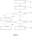
- step S3 will be described in detail below in connection with the work flow chart of a method for controlling a braking system of an electric vehicle according to another exemplary example of the present invention, shown in FIG. 3 .
- the step S3 may include steps S31 to S35.
- step S31 it is judged whether a brake strength Z1 of a first brake mode is greater than zero.
- Step S32 when the first brake mode is not put into use, the requested brake force of the various brake modes may be determined based at least on the total requested brake strength Zt and the priority of the brake mode respectively, i.e., a requested brake force F2 of the second brake mode and, when necessary, a requested brake force F3 of the third brake mode may be determined here.
- step S32 will be further described below in connection with the work flow chart of a method for controlling a braking system of an electric vehicle according to another exemplary example of the present invention, shown in FIG. 4 . Only the differences with the examples shown in FIG. 3 are set forth below, while the same steps are not repeated for brevity.
- the step S32 further includes steps S321S323.
- step S321 it is judged whether the total requested brake strength Zt is greater than the brake strength Z2 of the second brake mode. If the total requested brake strength Zt is greater than the brake strength Z2 of the second brake mode, then in step S322, the request brake force F2 is determined as the maximum available brake force F2max of the second brake mode and the requested brake force F3 is determined as a difference between the total request brake force Ft calculated based on the total requested brake strength Zt and the requested brake force F3 of the third brake mode. If the total requested brake strength Zt is not greater than the brake strength Z2 of the second brake mode, then in step S323, the requested brake force F2of the second brake mode is determined as the total requested brake force Ft calculated based on the total requested brake strength Zt.
- step S33 it is judged whether the total requested braking strength Zt is greater than the sum of the brake strength Z1 of the first brake mode and the brake strength Z2 of the second brake mode. If the total requested brake strength Zt is greater than the sum of the brake strength Z1 of the first brake mode and the brake strength Z2 of the second brake mode, in step S34, the requested brake force F1 of the first brake mode is determined as the maximum available brake force F1max of the first brake mode and the requested brake force F3 of the third brake mode is determined as the difference between the total requested brake force Ft calculated based on the requested brake force Zt and the requested brake force F1 of the first brake mode.
- Step S35 when the first brake mode is not put into use, the requested brake force of each brake mode may be determined based at least on the total requested brake strength Zt and the priority of the brake mode respectively, i.e., the requested brake force F1 of the second brake mode and the requested brake force F3 of the third brake mode may be determined here.
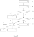
- step S35 will be further described in connection with the work flow chart of a method for controlling a braking system of an electric vehicle according to another exemplary example of the present invention, shown in FIG. 5 . Only the differences with the examples shown in FIG. 3 are set forth below, while the same steps are not repeated for brevity.
- the step S35 further includes steps S351S353.
- step S351 it is judged whether the total requested brake strength Zt is greater than the brake strength Z1 of the first brake mode. If the total requested brake strength Zt is greater than the brake strength Z1 of the first brake mode, in step S352, the requested brake force F1 of the first brake mode is determined as the maximum available brake force F1max of the first brake mode and the requested brake force F2 is determined as the difference between the total requested brake force Ft calculated based on the total requested brake strength Zt and the requested brake force F1 of the first brake mode. If the total requested brake strength Zt is not greater than the brake strength Z1 of the first brake mode, then in step S353, the requested brake force F1 of the first brake mode is determined as the total requested brake force Ft calculated based on the total requested brake strength Zt.
- only up to two brake modes are used in the braking process of an electric vehicle, thereby effectively inhibiting brake jitter in the braking process, improving the drive comfort of the vehicle, and simplifying the control strategy used to coordinate these brake modes, effectively reducing the hardware and software costs of continuous brake coordinators used to coordinate these brake modes.
- the retarder brake mode may be adopted as the first brake mode with a first priority
- the motor brake mode may be adopted as the second brake mode with a second priority
- the service brake mode may be adopted as the third brake mode with a third priority.
- the motor brake mode may be employed as a first brake mode with a first priority
- the retarder brake mode may be employed as a second brake mode with a second priority
- the service brake mode may be employed as a third brake mode with a third priority.
- serial numbers of the steps described herein do not necessarily represent a sequential order, but are merely reference numerals. Depending on the circumstances, the order may be changed as long as it achieves the technical objects of the present disclosure.
Landscapes
- Engineering & Computer Science (AREA)
- Transportation (AREA)
- Mechanical Engineering (AREA)
- Power Engineering (AREA)
- Chemical & Material Sciences (AREA)
- Combustion & Propulsion (AREA)
- Physics & Mathematics (AREA)
- Electromagnetism (AREA)
- Electric Propulsion And Braking For Vehicles (AREA)
- Regulating Braking Force (AREA)
Abstract
Description
- The present disclosure relates to the field of vehicle braking, particularly to a method for controlling a braking system of an electric vehicle, a braking system for an electric vehicle, and a computer program product used to at least assist in implementing the steps of the method according to the present disclosure.
- Most of the current vehicles only use a service brake for vehicle brakes, but high frequency and high intensity brakes may lead to wear and even brake failure of the service brake. In order to reduce or relieve the load of the service brake, a retarder may be installed in the vehicle. Moreover, for a vehicle with a motor installed, the motor may be operated in a generator mode to achieve brake energy recovery and improve its range. These brake modes can be simultaneously carried out into use by a continuous brake coordinator (EBC), but severe brake jitter can occur during the actual application. Therefore, the continuous brake coordinator needs to work with the Electronic Stabilization System (ESP) of the vehicle body to ensure vehicle body stability, which results in the existing continuous brake coordinator being put into use only in certain types of hybrid vehicles equipped with the Electronic Stabilization System and very high hardware and software costs.
- Considering that pure electric vehicles can be equipped with these brake modes as well, how to develop a continuous brake coordinator for pure electric vehicles is a current technical problem that needs to be solved.
- It is an aim of the present invention to provide a method for controlling a braking system of an electric vehicle, a braking system for an electric vehicle, and a computer program product to at least partially solve problems in the prior art.
- According to a first aspect of the present invention there is provided a method for controlling a braking system of an electric vehicle, the method comprising:
- step S1: determining a total requested brake strength of the braking system based at least on a brake request of the braking system and
a vehicle driving speed of the electric vehicle; - step S2: determining a brake strength of each brake mode of the braking system based at least on vehicle status information of the electric vehicle, wherein the braking system has at least three brake modes, and the brake modes have a preset priority; and
- step S3: determining a requested brake force of each brake mode based at least on the total requested brake strength and the priority of the brake mode when at most two brake modes are put into use.
- The core idea of the present disclosure is as follows: only up to two brake modes are used in the braking process of an electric vehicle, thereby effectively suppressing brake jitter in the brake process, improving the driving comfort of the vehicle, and simplifying the control strategy for coordinating these brake modes, effectively reducing the hardware and software costs of a continuous brake coordinator for coordinating these brake modes.
- According to a second aspect of the present invention, there is provided a braking system for an electric vehicle, wherein the system may comprise the following members:
- a vehicle status acquisition module configured to acquire vehicle status information for an electric vehicle, the vehicle status information including a vehicle driving speed;
- a brake request acquisition module configured to acquire a brake request of the braking system;
- at least three brake modules respectively for executing a brake of a different brake mode, the brake mode having a preset priority; and
- a control module configured to perform the method according to the present invention.
- According to a third aspect of the present disclosure, provided is a computer program product, such as a computer-readable program carrier comprising computer program instructions, wherein the computer program product at least assists in implementing the steps of the method according to the present invention when the computer program instructions are executed by a processor.
- In the following, the present disclosure is described in greater detail with reference to the accompanying drawings to provide a better understanding of its principles, features, and advantages. The accompanying drawings include the following:
-
FIG. 1 shows a work flow chart of a method for controlling a braking system of an electric vehicle according to an exemplary example of the present invention; -
FIG. 2 shows a structural block diagram of a braking system according to an exemplary example of the present disclosure; -
FIG. 3 shows a work flow chart of a method for controlling a braking system of an electric vehicle according to another exemplary example of the present invention; -
FIG. 4 shows a work flow chart of a method for controlling a braking system of an electric vehicle according to another exemplary example of the present invention; and -
FIG. 5 shows a work flow chart of a method for controlling a braking system of an electric vehicle according to another exemplary example of the present invention. - To provide a clearer understanding of the technical problems, technical solutions, and beneficial technical effects to be addressed by the present invention, the following detailed description of the present invention will be provided with reference to the accompanying drawings and multiple exemplary examples. It should be understood that the specific examples described herein are provided solely for the purpose of explaining the present disclosure and not for limiting the scope of protection of the present disclosure. In addition, it should be understood that in this document, terms such as "first," "second," "third," etc., are used for descriptive purposes only and should not be construed as indicating or implying relative importance. Furthermore, such terms should not be understood as implying a specific quantity of the indicated technical features.
-
FIG. 1 shows a work flow chart of a method for controlling a braking system of an electric vehicle according to an exemplary example of the present invention. The following exemplary examples describe the method in accordance with the present invention in more detail. - The method may comprise steps S1 to S3. In step S1, the total requested brake strength of the
brake system 1 may be determined based at least on the brake request of the braking system of the electric vehicle and the vehicle driving speed. In the meaning of the present invention, an electric vehicle refers to a pure electric vehicle with an in-vehicle power supply as the sole source of power, which is particularly distinct from hybrid vehicles that use internal combustion engines and electric motors as power sources, wherein the in-vehicle power supply may include one or more of a fuel cell, a lead acid cell, a nickel cell, and a lithium cell. A structural block diagram of oneexemplary braking system 1 of a fuel cell vehicle shown inFIG. 2 is set forth in detail below. - As shown in
FIG. 2 , thebraking system 1 includes a vehiclestatus acquisition module 11 configured to acquire various vehicle status information for an electric vehicle. The vehiclestatus acquisition module 11 may include an in-vehicle sensor mounted on an electric vehicle, such as a vehicle speed sensor measuring the driving speed of the vehicle, a wheel speed sensor measuring a wheel speed, i.e. wheel rotation speed, of the electric vehicle, and an in-vehicle temperature sensor measuring a motor temperature of the electric vehicle. The vehiclestatus acquisition module 11 may also include various in-vehicle control units of an electric vehicle, such as obtaining a battery charge status of the electric vehicle obtained by a battery management system, obtaining a retarder gear of the electric vehicle via a retarder control unit, etc. - Here, the
braking system 1 further includes a brakerequest acquisition module 12 configured to obtain a brake request of thebraking system 1. A driver's request for a brake of thebraking system 1 may be determined, inter alia, based on the depth (which is acquired by measuring the amount of travel displacement of the brake pedal) and/or the speed (which is acquired by measuring the amount of travel displacement variation of the brake pedal) of the driver's stepping on the brake pedal. For example, if the driver steps on the brake pedal deeply and quickly, a stronger brake request from the dr to thebraking system 1 is acquired. - The total requested brake strength of the
braking system 1, i.e., the total requested brake strength required to achieve a desired brake of the driver at the current driving speed, may be determined in thecontrol module 14 of thebraking system 1 based at least on the brake request of thebraking system 1 and the vehicle driving speed. - In step S2, the brake strength of each brake mode of the braking system is determined based at least on the vehicle status information of the electric vehicle, wherein the
braking system 1 has at least three braking modes and the brake mode has a preset priority. In the present example of the present invention, the brake mode of thebraking system 1 includes, for example, a retarder brake mode, a service brake mode, and a motor brake mode, etc. The threebrake modules 13 are exemplarily shown in the structural block diagram of thebraking system 1 ofFIG. 2 for executing brakes in different brake modes, the priority sequence of which may be adjusted according to vehicle design needs, rather than immobilized, such as a first brake mode set to have a first priority, a second brake mode having a second priority, and a third brake mode having a third priority. It is to be noted that the listed brake mode is merely exemplary and should not be limited thereto. - Exemplarily, in the motor brake mode, a brake force can be generated by regenerative brake, which refers to that the excess energy released during vehicle deceleration or braking process is used to make the motor operate in the condition of a generator while ensuring the brake efficiency of the vehicle, thereby converting the excess energy into electrical energy and storing the same in an in-vehicle energy storage device (e.g., an in-vehicle battery). The higher the wheel speed of the vehicle during the regenerative brake phase, the greater the brake strength of the motor brake mode. However, when the battery charge state is above a certain threshold, the regenerative brake of the motor brake mode needs to be limited to prevent the regenerative current from causing the in-vehicle battery to be overcharged. Moreover, when the motor temperature is too high, the resistance value inside the motor increases, which in turn causes the brake strength of the motor brake mode to decrease. Accordingly, the brake strength of the motor brake mode of the
braking system 1 may be determined based at least on the wheel speed, the battery charge state, and/or motor temperature of the electric vehicle. Moreover, the maximum brake force of the motor brake mode is also affected by the wheel speed, the battery charge state, and/or motor temperature of the electric vehicle. - For example, the brake strength of the retarder brake mode of the
braking system 1 may be determined based at least on a retarder gear of the electric vehicle. Typically, the retarder gear can be divided into a constant speed gear and a brake gear that may not be in a different gear, wherein the higher the gear of the brake gear, the higher the brake strength of the brake gear. Depending on the working principle, the retarder can be classified as an eddy current retarder, a hydraulic retarder, and an aerodynamic retarder, etc. For example, in the case of a hydraulic retarder, converting vehicle kinetic energy into thermal energy and removing the converted thermal energy through circulating coolant, especially the use of a high-speed brake gear for extended periods of time, can cause the coolant temperature in the hydraulic retarder to increase, thereby affecting the maximum available brake force of the hydraulic retarder. For example, in the case of an eddy current retarder, the excitation current flowing within a stator coil produces a stator magnetic field, and the rotor rotates with the drive shaft and cuts the magnetic line of the stator magnetic field, thereby generating eddy current-like induced current inside the rotor. The stator magnetic field applies an electromagnetic force to the rotor that impedes rotor rotation, thereby generating a brake force, which can be adjusted by the excitation current flowing in the stator coil. Here, the greater the excitation current, the stronger the stator magnetic field and the greater the maximum available brake force of the eddy current retarder. - For example, in the service brake mode, the driving speed of the vehicle can be reduced by a hydraulic brake mechanism built on the basis of the Pascal's Law, and the brake strength thereof is influenced by factors such as coefficient of ground adhesion, wheel load, and wheel radius. Under the premise that the safety requirements of the entire vehicle brake are met, the maximum available brake force of the service brake mode is generally sufficient to satisfy the brake request of the driver in non-urgent situations. Therefore, the maximum available brake force of the service brake mode may be considered to be unrestricted in the meaning of the present invention.
- In step S3, with up to two brake modes put into use, the requested brake force of each brake mode is determined based, at least, on the total requested brake strength and the priority of the brake mode, respectively. In the prior art, multiple brake modes, such as the motor brake mode, the retarder brake mode, the regenerative brake mode, and the service brake mode, are generally used simultaneously in the braking system of a hybrid vehicle, which can cause severe brake jitter during the braking process. Therefore, in these hybrid vehicles, the continuous brake coordinator needs to work with the vehicle body electronic stabilization system to ensure the vehicle body stability, which greatly increases the costs of software and hardware of vehicle system design. In an example of the present invention, only up to two brake modes are used in the braking process of an electric vehicle, i.e., only one brake mode or two brake modes are used. Here, the requested brake force of the brake mode put in use does not exceed its maximum available brake force, and thus it can simplify the control strategy used to coordinate these brake modes and effectively reduce the hardware and software costs of the continuous brake coordinator used to coordinate these brake modes.
- The step S3 will be described in detail below in connection with the work flow chart of a method for controlling a braking system of an electric vehicle according to another exemplary example of the present invention, shown in
FIG. 3 . As shown inFIG. 3 , the step S3 may include steps S31 to S35. In step S31, it is judged whether a brake strength Z1 of a first brake mode is greater than zero. If the brake strength Z1 of the first brake mode is not greater than zero, in Step S32, when the first brake mode is not put into use, the requested brake force of the various brake modes may be determined based at least on the total requested brake strength Zt and the priority of the brake mode respectively, i.e., a requested brake force F2 of the second brake mode and, when necessary, a requested brake force F3 of the third brake mode may be determined here. - The step S32 will be further described below in connection with the work flow chart of a method for controlling a braking system of an electric vehicle according to another exemplary example of the present invention, shown in
FIG. 4 . Only the differences with the examples shown inFIG. 3 are set forth below, while the same steps are not repeated for brevity. - As shown in
FIG. 4 , the step S32 further includes steps S321S323. In step S321, it is judged whether the total requested brake strength Zt is greater than the brake strength Z2 of the second brake mode. If the total requested brake strength Zt is greater than the brake strength Z2 of the second brake mode, then in step S322, the request brake force F2 is determined as the maximum available brake force F2max of the second brake mode and the requested brake force F3 is determined as a difference between the total request brake force Ft calculated based on the total requested brake strength Zt and the requested brake force F3 of the third brake mode. If the total requested brake strength Zt is not greater than the brake strength Z2 of the second brake mode, then in step S323, the requested brake force F2of the second brake mode is determined as the total requested brake force Ft calculated based on the total requested brake strength Zt. - If the brake strength Z1 of the first brake mode is greater than zero, then in step S33, it is judged whether the total requested braking strength Zt is greater than the sum of the brake strength Z1 of the first brake mode and the brake strength Z2 of the second brake mode. If the total requested brake strength Zt is greater than the sum of the brake strength Z1 of the first brake mode and the brake strength Z2 of the second brake mode, in step S34, the requested brake force F1 of the first brake mode is determined as the maximum available brake force F1max of the first brake mode and the requested brake force F3 of the third brake mode is determined as the
difference between the total requested brake force Ft calculated based on the requested brake force Zt and the requested brake force F1 of the first brake mode. If the total request brake strength Zt is not greater than the sum of the brake strength Z1 of the first brake mode and the brake strength Z2 of the second brake mode, then in Step S35, when the first brake mode is not put into use, the requested brake force of each brake mode may be determined based at least on the total requested brake strength Zt and the priority of the brake mode respectively, i.e., the requested brake force F1 of the second brake mode and the requested brake force F3 of the third brake mode may be determined here. - The step S35 will be further described in connection with the work flow chart of a method for controlling a braking system of an electric vehicle according to another exemplary example of the present invention, shown in
FIG. 5 . Only the differences with the examples shown inFIG. 3 are set forth below, while the same steps are not repeated for brevity. - As shown in
FIG. 5 , the step S35 further includes steps S351S353. In step S351, it is judged whether the total requested brake strength Zt is greater than the brake strength Z1 of the first brake mode. If the total requested brake strength Zt is greater than the brake strength Z1 of the first brake mode, in step S352, the requested brake force F1 of the first brake mode is determined as the maximum available brake force F1max of the first brake mode and the requested brake force F2 is determined as the difference between the total requested brake force Ft calculated based on the total requested brake strength Zt and the requested brake force F1 of the first brake mode. If the total requested brake strength Zt is not greater than the brake strength Z1 of the first brake mode, then in step S353, the requested brake force F1 of the first brake mode is determined as the total requested brake force Ft calculated based on the total requested brake strength Zt. - According to examples of the present invention, only up to two brake modes are used in the braking process of an electric vehicle, thereby effectively inhibiting brake jitter in the braking process, improving the drive comfort of the vehicle, and simplifying the control strategy used to coordinate these brake modes, effectively reducing the hardware and software costs of continuous brake coordinators used to coordinate these brake modes.
- In an optional example of the present invention, the retarder brake mode may be adopted as the first brake mode with a first priority, and the motor brake mode may be adopted as the second brake mode with a second priority, and the service brake mode may be adopted as the third brake mode with a third priority. By using the motor brake mode and the service brake mode in a cooperative manner with the retarder brake mode while giving priority to the retarder brake mode, a smoother brake effect can be obtained and the brake strength and brake frequency of the service braking can be reduced as much as possible, thereby effectively extending the service life of the service brake and reducing the effects of thermal fading of the service brake due to high intensity and high frequency of service braking.
- In another optional example of the present invention, the motor brake mode may be employed as a first brake mode with a first priority, and the retarder brake mode may be employed as a second brake mode with a second priority, and the service brake mode may be employed as a third brake mode with a third priority. By using the retarder brake mode and the service brake mode in a cooperative manner with the motor brake mode while giving priority to the motor brake mode, the excess energy during the braking process of the electric vehicle can be recovered as much as possible to improve the range of the electric vehicle while minimizing the brake strength and brake frequency of service braking, thereby effectively extending the service life of the service brake and reducing the effects of thermal fading of the service brake due to high intensity and high frequency of service braking.
- In addition, it should be noted that the serial numbers of the steps described herein do not necessarily represent a sequential order, but are merely reference numerals. Depending on the circumstances, the order may be changed as long as it achieves the technical objects of the present disclosure.
- Although specific embodiments have been described above, these embodiments are not intended to limit the scope of the present disclosure, even when described with respect to specific features of individual embodiments. The examples of features provided in the present disclosure are intended to be illustrative and not limiting, unless otherwise specified. In a specific implementation, multiple features may be combined with one another as per actual requirements and when technically feasible. Various substitutions, alterations, and modifications may be conceived without departing from the spirit and scope of the present disclosure.
Claims (12)
- A method for controlling a braking system (1) of an electric vehicle, the method comprising:step S1: determining a total requested brake strength of the braking system (1) based at least on a brake request of the braking system (1) and a vehicle driving speed of the electric vehicle;step S2: determining a brake strength of each brake mode of the braking system (1) based at least on vehicle status information of the electric vehicle, wherein the braking system (1) has at least three brake modes, and the brake modes have a preset priority; andstep S3: determining a requested brake force of each brake mode based at least on the total requested brake strength and the priority of the brake mode when at most two brake modes are put into use.
- The method according to Claim 1, wherein the brake mode of the braking system (1) includes a retarder brake mode, a service brake mode, and a motor brake mode.
- The method according to Claim 2, wherein the retarder brake mode is employed as a first brake mode having a first priority, and the motor brake mode is employed as a second brake mode having a second priority, and the service brake mode is employed as a third brake mode having a third priority.
- The method according to Claim 2, wherein the motor brake mode is employed as a first brake mode with a first priority, and the retarder brake mode is employed as a second brake mode with a second priority, and the service brake mode is employed as a third brake mode with a third priority.
- The method according to Claim 2, wherein the requested brake force for each brake mode is determined separately such that the requested brake force of each brake mode does not exceed its maximum available brake force.
- The method according to any one of Claims 2 to 5, wherein the brake strength of the motor brake mode of the braking system (1) is determined based at least on a wheel speed, a battery charge state, and/or a motor temperature of the electric vehicle.
- The method according to any one of Claims 2 to 5, wherein the brake strength of the retarder brake mode of the braking system (1) is determined based at least on a retarder gear of the electric vehicle.
- The method according to any one of Claims 3 to 5, wherein step S3 further comprises:step S31: judging whether the brake strength of the first brake mode is greater than zero;step S32: if the brake strength of the first brake mode is not greater than zero, then determining the requested brake force of each brake mode based at least on the total requested brake strength and the priority of the brake mode respectively when the first brake mode is not put into use;step S33: if the brake strength of the first brake mode is greater than zero, determining whether the total requested brake strength is greater than a sum of the brake strength of the first brake mode and the brake strength of the second brake mode;step S34: if the total requested brake strength is greater than the sum of the brake strength of the first brake mode and the brake strength of the second brake mode, determining the requested brake force of the first brake mode as the maximum available brake force of the first brake mode and determining the requested brake force of the third brake mode as a difference between the total requested brake force calculated based on the total requested brake strength and the requested brake force of the first brake mode; andstep S35: if the total requested brake strength is not greater than the sum of the brake strength of the first brake mode and the brake strength of the second brake mode, then determining the requested brake force of each brake mode based at least on the total requested brake strength and the priority of the brake mode respectively when the first brake mode is not put into use.
- The method according to Claim 8, wherein the step S32 further comprises:step S321: judging whether the total requested brake strength is greater than the brake strength of the second brake mode;step S322: if the total requested brake strength is greater than the brake strength of the second brake mode, determining the requested brake force of the second brake mode as the maximum available brake force of the second brake mode and determining the requested brake force of the third brake mode as a difference between the total requested brake force calculated based on the total requested brake strength and the requested brake force of the third brake mode;
andstep S323: determining the requested brake force of the second brake mode as a total requested brake force calculated based on the total requested brake strength if the total requested brake strength is not greater than the brake strength of the second brake mode. - The method according to Claim 8, wherein the step S35 further comprises:step S351: judging whether the total requested brake strength is greater than the brake strength of the first brake mode;step S352: if the total requested brake strength is greater than the brake strength of the first brake mode, determining the requested brake force of the first brake mode as the maximum available brake force of the first brake mode and determining the requested brake force of the second brake mode as a difference between the total requested brake force calculated based on the total requested brake strength and the requested brake force of the first brake mode; andstep S353: determining the requested brake force of the first brake mode as a total requested brake force calculated based on the total requested brake strength if the total requested brake strength is not greater than the brake strength of the first brake mode.
- A braking system(1) for an electric vehicle, wherein the system (1) comprises the following members:a vehicle status acquisition module (11) configured to acquire vehicle status information for an electric vehicle, the vehicle status information including a vehicle driving speed;a brake request acquisition module (12) configured to acquire a brake request of the braking system (1);at least three brake modules (13) respectively for executing a brake of a different brake mode, the brake mode having a preset priority; anda control module (14) configured to perform the method according to any one of the preceding claims.
- A computer program product, such as a computer-readable program carrier comprising computer program instructions, at least assisting in implementing the steps of the method according to any one of Claims 1 to 10 when the computer program instructions are executed by a processor.
Applications Claiming Priority (1)
| Application Number | Priority Date | Filing Date | Title |
|---|---|---|---|
| CN202311767469.3A CN120171305A (en) | 2023-12-20 | 2023-12-20 | Method for controlling a braking system of an electric vehicle and braking system |
Publications (1)
| Publication Number | Publication Date |
|---|---|
| EP4574588A1 true EP4574588A1 (en) | 2025-06-25 |
Family
ID=93893486
Family Applications (1)
| Application Number | Title | Priority Date | Filing Date |
|---|---|---|---|
| EP24218962.9A Pending EP4574588A1 (en) | 2023-12-20 | 2024-12-11 | Method for controlling braking system of electric vehicle and braking system |
Country Status (3)
| Country | Link |
|---|---|
| EP (1) | EP4574588A1 (en) |
| JP (1) | JP2025098981A (en) |
| CN (1) | CN120171305A (en) |
Families Citing this family (1)
| Publication number | Priority date | Publication date | Assignee | Title |
|---|---|---|---|---|
| CN120396905A (en) * | 2025-07-02 | 2025-08-01 | 湖南行必达网联科技有限公司 | Maximum available braking force calculation method, device, equipment and medium |
Citations (2)
| Publication number | Priority date | Publication date | Assignee | Title |
|---|---|---|---|---|
| KR20210072172A (en) * | 2019-12-06 | 2021-06-17 | 현대자동차주식회사 | Braking control method for electric vehicle |
| CN108248582B (en) * | 2018-02-13 | 2023-10-27 | 隆中控股集团股份有限公司 | Electric control braking method for automobile and computer storage medium |
-
2023
- 2023-12-20 CN CN202311767469.3A patent/CN120171305A/en active Pending
-
2024
- 2024-12-11 EP EP24218962.9A patent/EP4574588A1/en active Pending
- 2024-12-19 JP JP2024223871A patent/JP2025098981A/en active Pending
Patent Citations (2)
| Publication number | Priority date | Publication date | Assignee | Title |
|---|---|---|---|---|
| CN108248582B (en) * | 2018-02-13 | 2023-10-27 | 隆中控股集团股份有限公司 | Electric control braking method for automobile and computer storage medium |
| KR20210072172A (en) * | 2019-12-06 | 2021-06-17 | 현대자동차주식회사 | Braking control method for electric vehicle |
Also Published As
| Publication number | Publication date |
|---|---|
| JP2025098981A (en) | 2025-07-02 |
| CN120171305A (en) | 2025-06-20 |
Similar Documents
| Publication | Publication Date | Title |
|---|---|---|
| JP6444889B2 (en) | Method for reducing torque energy to boost hybrid vehicle acceleration | |
| US8002057B2 (en) | Hybrid drive system | |
| KR20190028121A (en) | Method for controlling e-4wd hybrid vehicle | |
| CN103702881B (en) | The control method of vehicle and vehicle | |
| JP5664769B2 (en) | Vehicle and vehicle control method | |
| CN101402360A (en) | Power generation control method for motor of hybrid power automobile | |
| EP2423064A1 (en) | Vehicle control unit and vehicle control method | |
| JP5747724B2 (en) | Vehicle and vehicle control method | |
| EP3984845B1 (en) | Electric device control method and electric device | |
| CN112109698A (en) | Vehicle control method, device, medium and vehicle | |
| EP4574588A1 (en) | Method for controlling braking system of electric vehicle and braking system | |
| CN101186210A (en) | Method for controlling motor assistant drive of mixed power vehicle | |
| WO2010143077A2 (en) | Method and system for controlling an electric motor in a hybrid vehicle | |
| JP2011188557A (en) | System and method for controlling extension of distance-to-empty by powering regenerative distribution | |
| JP4595829B2 (en) | Secondary battery control device and control method | |
| JP6075018B2 (en) | Electric vehicle control device, electric vehicle including the same, and electric vehicle control method | |
| JP2015223954A (en) | Hybrid electric vehicle and hybrid electric vehicle control method | |
| JP2014007905A (en) | Controller for motor drive system | |
| JP2000013914A (en) | Power limiting device for vehicle provided with storage battery | |
| JP2011255837A (en) | Device for control of hybrid vehicle | |
| CN106256636B (en) | Apparatus and method for controlling torque reduction of hybrid electric vehicle | |
| KR20240140575A (en) | Motor Charging Control Method for Improving Fuel Efficiency of Hybrid Vehicle | |
| JP5339091B2 (en) | Hybrid car | |
| JP2010125877A (en) | Controller for hybrid electric vehicle | |
| CN120481954B (en) | Braking control method and device for range-extended vehicle and range-extended Cheng Kuangche |
Legal Events
| Date | Code | Title | Description |
|---|---|---|---|
| PUAI | Public reference made under article 153(3) epc to a published international application that has entered the european phase |
Free format text: ORIGINAL CODE: 0009012 |
|
| STAA | Information on the status of an ep patent application or granted ep patent |
Free format text: STATUS: THE APPLICATION HAS BEEN PUBLISHED |
|
| AK | Designated contracting states |
Kind code of ref document: A1 Designated state(s): AL AT BE BG CH CY CZ DE DK EE ES FI FR GB GR HR HU IE IS IT LI LT LU LV MC ME MK MT NL NO PL PT RO RS SE SI SK SM TR |
|
| STAA | Information on the status of an ep patent application or granted ep patent |
Free format text: STATUS: REQUEST FOR EXAMINATION WAS MADE |
|
| 17P | Request for examination filed |
Effective date: 20260102 |
|
| GRAP | Despatch of communication of intention to grant a patent |
Free format text: ORIGINAL CODE: EPIDOSNIGR1 |
|
| STAA | Information on the status of an ep patent application or granted ep patent |
Free format text: STATUS: GRANT OF PATENT IS INTENDED |
|
| RIC1 | Information provided on ipc code assigned before grant |
Ipc: B60T 1/10 20060101AFI20260317BHEP Ipc: B60L 7/18 20060101ALI20260317BHEP Ipc: B60L 7/26 20060101ALI20260317BHEP Ipc: B60L 15/20 20060101ALI20260317BHEP Ipc: B60T 13/58 20060101ALI20260317BHEP |