EP4574578A1 - Vehicle - Google Patents
Vehicle Download PDFInfo
- Publication number
- EP4574578A1 EP4574578A1 EP24213205.8A EP24213205A EP4574578A1 EP 4574578 A1 EP4574578 A1 EP 4574578A1 EP 24213205 A EP24213205 A EP 24213205A EP 4574578 A1 EP4574578 A1 EP 4574578A1
- Authority
- EP
- European Patent Office
- Prior art keywords
- vehicle
- electric circuit
- battery
- relay
- relay unit
- Prior art date
- Legal status (The legal status is an assumption and is not a legal conclusion. Google has not performed a legal analysis and makes no representation as to the accuracy of the status listed.)
- Pending
Links
Images


Classifications
-
- B—PERFORMING OPERATIONS; TRANSPORTING
- B60—VEHICLES IN GENERAL
- B60R—VEHICLES, VEHICLE FITTINGS, OR VEHICLE PARTS, NOT OTHERWISE PROVIDED FOR
- B60R16/00—Electric or fluid circuits specially adapted for vehicles and not otherwise provided for; Arrangement of elements of electric or fluid circuits specially adapted for vehicles and not otherwise provided for
- B60R16/02—Electric or fluid circuits specially adapted for vehicles and not otherwise provided for; Arrangement of elements of electric or fluid circuits specially adapted for vehicles and not otherwise provided for electric constitutive elements
-
- B—PERFORMING OPERATIONS; TRANSPORTING
- B60—VEHICLES IN GENERAL
- B60R—VEHICLES, VEHICLE FITTINGS, OR VEHICLE PARTS, NOT OTHERWISE PROVIDED FOR
- B60R16/00—Electric or fluid circuits specially adapted for vehicles and not otherwise provided for; Arrangement of elements of electric or fluid circuits specially adapted for vehicles and not otherwise provided for
- B60R16/02—Electric or fluid circuits specially adapted for vehicles and not otherwise provided for; Arrangement of elements of electric or fluid circuits specially adapted for vehicles and not otherwise provided for electric constitutive elements
- B60R16/023—Electric or fluid circuits specially adapted for vehicles and not otherwise provided for; Arrangement of elements of electric or fluid circuits specially adapted for vehicles and not otherwise provided for electric constitutive elements for transmission of signals between vehicle parts or subsystems
- B60R16/0238—Electrical distribution centers
-
- B—PERFORMING OPERATIONS; TRANSPORTING
- B60—VEHICLES IN GENERAL
- B60L—PROPULSION OF ELECTRICALLY-PROPELLED VEHICLES; SUPPLYING ELECTRIC POWER FOR AUXILIARY EQUIPMENT OF ELECTRICALLY-PROPELLED VEHICLES; ELECTRODYNAMIC BRAKE SYSTEMS FOR VEHICLES IN GENERAL; MAGNETIC SUSPENSION OR LEVITATION FOR VEHICLES; MONITORING OPERATING VARIABLES OF ELECTRICALLY-PROPELLED VEHICLES; ELECTRIC SAFETY DEVICES FOR ELECTRICALLY-PROPELLED VEHICLES
- B60L3/00—Electric devices on electrically-propelled vehicles for safety purposes; Monitoring operating variables, e.g. speed, deceleration or energy consumption
-
- B—PERFORMING OPERATIONS; TRANSPORTING
- B62—LAND VEHICLES FOR TRAVELLING OTHERWISE THAN ON RAILS
- B62D—MOTOR VEHICLES; TRAILERS
- B62D25/00—Superstructure or monocoque structure sub-units; Parts or details thereof not otherwise provided for
- B62D25/08—Front or rear portions
- B62D25/16—Mud-guards or wings; Wheel cover panels
-
- H—ELECTRICITY
- H01—ELECTRIC ELEMENTS
- H01H—ELECTRIC SWITCHES; RELAYS; SELECTORS; EMERGENCY PROTECTIVE DEVICES
- H01H50/00—Details of electromagnetic relays
- H01H50/02—Bases; Casings; Covers
- H01H50/021—Bases; Casings; Covers structurally combining a relay and an electronic component, e.g. varistor, RC circuit
-
- H—ELECTRICITY
- H02—GENERATION; CONVERSION OR DISTRIBUTION OF ELECTRIC POWER
- H02J—ELECTRIC POWER NETWORKS; CIRCUIT ARRANGEMENTS OR SYSTEMS FOR SUPPLYING OR DISTRIBUTING ELECTRIC POWER; SYSTEMS FOR STORING ELECTRIC ENERGY
- H02J7/00—Circuit arrangements for charging or discharging batteries or for supplying loads from batteries
- H02J7/34—Parallel operation in networks using both storage and other DC sources, e.g. providing buffering
- H02J7/342—The other DC source being a battery actively interacting with the first one, i.e. battery to battery charging
-
- B—PERFORMING OPERATIONS; TRANSPORTING
- B60—VEHICLES IN GENERAL
- B60L—PROPULSION OF ELECTRICALLY-PROPELLED VEHICLES; SUPPLYING ELECTRIC POWER FOR AUXILIARY EQUIPMENT OF ELECTRICALLY-PROPELLED VEHICLES; ELECTRODYNAMIC BRAKE SYSTEMS FOR VEHICLES IN GENERAL; MAGNETIC SUSPENSION OR LEVITATION FOR VEHICLES; MONITORING OPERATING VARIABLES OF ELECTRICALLY-PROPELLED VEHICLES; ELECTRIC SAFETY DEVICES FOR ELECTRICALLY-PROPELLED VEHICLES
- B60L2210/00—Converter types
- B60L2210/10—DC to DC converters
- B60L2210/12—Buck converters
-
- B—PERFORMING OPERATIONS; TRANSPORTING
- B60—VEHICLES IN GENERAL
- B60L—PROPULSION OF ELECTRICALLY-PROPELLED VEHICLES; SUPPLYING ELECTRIC POWER FOR AUXILIARY EQUIPMENT OF ELECTRICALLY-PROPELLED VEHICLES; ELECTRODYNAMIC BRAKE SYSTEMS FOR VEHICLES IN GENERAL; MAGNETIC SUSPENSION OR LEVITATION FOR VEHICLES; MONITORING OPERATING VARIABLES OF ELECTRICALLY-PROPELLED VEHICLES; ELECTRIC SAFETY DEVICES FOR ELECTRICALLY-PROPELLED VEHICLES
- B60L2210/00—Converter types
- B60L2210/40—DC to AC converters
-
- B—PERFORMING OPERATIONS; TRANSPORTING
- B60—VEHICLES IN GENERAL
- B60R—VEHICLES, VEHICLE FITTINGS, OR VEHICLE PARTS, NOT OTHERWISE PROVIDED FOR
- B60R16/00—Electric or fluid circuits specially adapted for vehicles and not otherwise provided for; Arrangement of elements of electric or fluid circuits specially adapted for vehicles and not otherwise provided for
- B60R16/02—Electric or fluid circuits specially adapted for vehicles and not otherwise provided for; Arrangement of elements of electric or fluid circuits specially adapted for vehicles and not otherwise provided for electric constitutive elements
- B60R16/03—Electric or fluid circuits specially adapted for vehicles and not otherwise provided for; Arrangement of elements of electric or fluid circuits specially adapted for vehicles and not otherwise provided for electric constitutive elements for supply of electrical power to vehicle subsystems or for
- B60R16/033—Electric or fluid circuits specially adapted for vehicles and not otherwise provided for; Arrangement of elements of electric or fluid circuits specially adapted for vehicles and not otherwise provided for electric constitutive elements for supply of electrical power to vehicle subsystems or for characterised by the use of electrical cells or batteries
-
- H—ELECTRICITY
- H02—GENERATION; CONVERSION OR DISTRIBUTION OF ELECTRIC POWER
- H02J—ELECTRIC POWER NETWORKS; CIRCUIT ARRANGEMENTS OR SYSTEMS FOR SUPPLYING OR DISTRIBUTING ELECTRIC POWER; SYSTEMS FOR STORING ELECTRIC ENERGY
- H02J2207/00—Details of circuit arrangements for charging or discharging batteries or supplying loads from batteries
- H02J2207/20—Charging or discharging characterised by the power electronics converter
-
- Y—GENERAL TAGGING OF NEW TECHNOLOGICAL DEVELOPMENTS; GENERAL TAGGING OF CROSS-SECTIONAL TECHNOLOGIES SPANNING OVER SEVERAL SECTIONS OF THE IPC; TECHNICAL SUBJECTS COVERED BY FORMER USPC CROSS-REFERENCE ART COLLECTIONS [XRACs] AND DIGESTS
- Y02—TECHNOLOGIES OR APPLICATIONS FOR MITIGATION OR ADAPTATION AGAINST CLIMATE CHANGE
- Y02T—CLIMATE CHANGE MITIGATION TECHNOLOGIES RELATED TO TRANSPORTATION
- Y02T10/00—Road transport of goods or passengers
- Y02T10/60—Other road transportation technologies with climate change mitigation effect
- Y02T10/70—Energy storage systems for electromobility, e.g. batteries
Definitions
- the technology disclosed in the present specification relates to a vehicle.
- Japanese Unexamined Patent Application Publication No. 2020-088934 describes a relay unit installed in a vehicle.
- the relay unit electrically connects a battery of the vehicle and a plurality of on-board loads.
- the present specification provides technology for suppressing effects from damage to the casing of the relay unit on the electric circuit inside the casing.
- the technology disclosed in the present specification is embodied as a vehicle.
- the vehicle includes a vehicle body, a plurality of wheels that supports the vehicle body, a motor that drives at least one of the wheels, a battery that is electrically connected to the motor, a relay unit electrically connected to the battery, and at least one electric unit that is electrically connected to the relay unit.
- the relay unit includes a casing, at least one relay that is disposed inside the casing and that includes a first terminal and a second terminal, a first electric circuit that is disposed inside the casing and that electrically connects the battery to the first terminal of the relay, and a second electric circuit that is disposed inside the casing and that electrically connects the at least one electric unit to the second terminal of the relay.
- the first electric circuit is situated further toward an inward side of the vehicle than the second electric circuit, in a right-left direction of the vehicle.
- the relay is provided in the relay unit, and the electric circuit in the relay unit is divided into the first electric circuit and the second electric circuit with the relay as a boundary.
- the first electric circuit which is electrically connected to the battery, is situated further on an inner side of the vehicle than the second electric circuit, in the right-left direction of the vehicle. According to such a configuration, even when the casing of the relay unit is damaged from a sideward direction of the vehicle, effects on the first electric circuit are suppressed. On the other hand, although there is a risk that the second electric circuit may be affected, the second electric circuit can be electrically disconnected from the battery by the relay.
- a vehicle may include a vehicle body, a plurality of wheels that supports the vehicle body, a motor that drives at least one of the wheels, a battery that is electrically connected to the motor, a relay unit electrically connected to the battery, and at least one electric unit electrically connected to the relay unit.
- the relay unit may include a casing, at least one relay that is disposed inside the casing and that includes a first terminal and a second terminal, a first electric circuit that is disposed inside the casing and that electrically connects the battery to the first terminal of the relay, and a second electric circuit that is disposed inside the casing and that electrically connects the at least one electric unit to the second terminal of the relay.
- the first electric circuit may be situated further toward an inward side of the vehicle than the second electric circuit, in a right-left direction of the vehicle.
- the relay in addition to any one of the first to fourth aspects described above, the relay may be maintained in an open state while the vehicle is travelling. According to such a configuration, even in the event of a collision of the vehicle in which the second electric circuit is externally exposed, for example, the second electric circuit can be reliably disconnected from the battery.
- the vehicle 10 according to an embodiment is a battery electric vehicle (BEV).
- BEV battery electric vehicle
- the vehicle 10 is not limited to a BEV, and may be another type of electrified vehicle, such as a hybrid electric vehicle (HEV) or a plug-in hybrid electric vehicle (PHEV).
- HEV hybrid electric vehicle
- PHEV plug-in hybrid electric vehicle
- the vehicle 10 includes a battery unit 26, a motor unit 28, a power control unit (PCU) 30, a relay unit 32, a charging inlet 40, an auxiliary battery 42, a direct current (DC)-to-DC converter 44, an air conditioning compressor 46, a compressor inverter 48, a power feed outlet 50, and a power feed inverter 52.
- PCU power control unit
- DC direct current
- the PCU 30 is electrically connected to each of the battery 26b and the motor unit 28.
- the PCU 30 includes an inverter, a converter, and so forth.
- the PCU 30 controls supplied electric power between the battery 26b and the motor unit 28.
- the PCU 30 controls regenerative electric power supplied from the motor unit 28 to the battery 26b.
- the PCU 30 may be disposed in the front compartment 12f and also above the motor unit 28, although not limited thereto in particular.
- the relay unit 32 is electrically connected to the battery 26b via the system main relay 26c. Also, the relay unit 32 is electrically connected to each of a plurality of electric units 40, 44, 48, and 52. The relay unit 32 electrically relays between the battery 26b and the electric units 40, 44, 48, and 52.
- the electric units 40, 44, 48, and 52 include the charging inlet 40, a DC-to-DC converter 44, the compressor inverter 48, and the power feed inverter 52, although not limited thereto in particular.
- the relay unit 32 is disposed inside the rear compartment 12r, and more specifically, is disposed below the luggage room 12r1.
- the relay unit 32 is disposed between the wheel wells 20 in the right-left direction. More specifically, at least one outer peripheral surface of the relay unit 32 faces a wheel well 20. Specifically, the relay unit 32 is closer to the wheel well 20 than the other electric units 44, 48, 52, and so forth, which are disposed inside the rear compartment 12r.
- the charging inlet 40 is situated at the rearward portion of the vehicle body 12.
- the charging inlet 40 is connected to an external direct current power supply via a cable 2.
- the charging inlet 40 is configured so that a connector 4 of the cable 2 is detachably attachable.
- the external direct current power supply is, for example, a charging station or the like.
- the charging inlet 40 receives charging electric power from an external direct current power supply to charge the battery 26b.
- the auxiliary battery 42 has a secondary battery cell and is configured to be capable of being charged and discharged.
- the rated voltage of the auxiliary battery 42 is approximately 12 volts.
- the auxiliary battery 42 is connected to various types of control systems and other accessories of the vehicle 10, and supplies electric power thereto.
- the secondary battery cells may be lithium-ion battery cells or all-solid-state battery cells, for example, although not limited thereto in particular.
- the auxiliary battery 42 is disposed below the luggage room 12r1 of the rear compartment 12r.
- the DC-to-DC converter 44 is connected to the auxiliary battery 42.
- the auxiliary battery 42 is electrically connected to the relay unit 32 via the DC-to-DC converter 44.
- the DC-to-DC converter 44 is configured to be able to convert the direct current electric power from the battery 26b into low-voltage (e.g., 30 volts or lower) direct current electric power to be supplied to the auxiliary battery 42.
- the DC-to-DC converter 44 is disposed below the luggage room 12r1 of the rear compartment 12r.
- the air conditioning compressor 46 is a device that compresses refrigerant gas in an air conditioning heat pump circuit installed in the vehicle 10.
- the air conditioning compressor 46 is connected to the relay unit 32 via a compressor inverter 48.
- the compressor inverter 48 is configured to be able to convert direct current electric power from the battery 26b into alternating current power to be supplied to the air conditioning compressor 46.
- the compressor inverter 48 adjusts the supplied electric power to the air conditioning compressor 46 to control operations of the air conditioning compressor 46.
- the compressor inverter 48 is disposed below the luggage room 12r1 of the rear compartment 12r.
- the power feed outlet 50 is configured such that electric equipment can be detachably attached thereto.
- the power feed outlet 50 outputs direct current electric power to the electric equipment.
- the power feed outlet 50 is configured to be capable of high-output power feeding, from 600 watts or more to 1500 watts or less for example, although not limited thereto in particular.
- Electric equipment referred to here includes, for example, home appliances (such as hair dryers, water boilers, and so forth), personal computers, smartphones, tablet terminals, and the like.
- the power feed outlet 50 is disposed inside the cabin 12c.
- the power feed inverter 52 is connected to the power feed outlet 50.
- the power feed outlet 50 is connected to the relay unit 32 via the power feed inverter 52.
- the power feed inverter 52 is configured to be capable of converting direct current electric power from the battery 26b into alternating current electric power that is supplied to the outside of the vehicle 10 through the power feed outlet 50.
- the power feed inverter 52 is disposed below the luggage room 12r1 of the rear compartment 12r.
- the power feed inverter 52 is an example of a "power feeding electric power conversion circuit" in the present technology.
- the relay unit 32 is electrically connected to the battery 26b via the system main relay 26c and a first cable 54.
- the first cable 54 has a first connector 54a.
- the first connector 54a is configured to be detachably attachable to the relay unit 32.
- the relay unit 32 is connected to the charging inlet 40 via a second cable 56.
- the second cable 56 has a second connector 56a.
- the second connector 56a is configured to be detachably attachable to the relay unit 32.
- the relay unit 32 is connected to the DC-to-DC converter 44 via a third cable 58.
- the third cable 58 has a third connector 58a.
- the third connector 58a is configured to be detachably attachable to the relay unit 32.
- the relay unit 32 is connected to the compressor inverter 48 via a fourth cable 60.
- the fourth cable 60 has a fourth connector 60a.
- the fourth connector 60a is configured to be detachably attachable to the relay unit 32.
- the relay unit 32 is connected to the power feed inverter 52 via a fifth cable 62.
- the fifth cable 62 has a fifth connector 62a.
- the fifth connector 62a is configured to be detachably attachable to the relay unit 32.
- the relay unit 32 has a casing 34.
- the casing 34 is made up of a metal such as an aluminum-based material or the like, for example.
- the casing 34 has a generally cuboid shape, with an upper surface and a lower surface (omitted from illustration) and a front side surface 34s1, a left side surface 34s2, a rear side surface 34s3, and a right side surface 34s4, disposed therebetween.
- the right side surface 34s4 of the casing 34 faces the wheel well 20 situated at the right end of the vehicle body 12.
- the casing 34 has a first connector port 34a, a second connector port 34b, a third connector port 34c, a fourth connector port 34d, and a fifth connector port 34e.
- the first connector port 34a is situated on a front side surface 34s1 of the casing 34.
- the second connector port 34b is situated on the rear side surface 34s3 of the casing 34.
- the third connector port 34c and the fourth connector port 34d are situated on the left side surface 34s2 of the casing 34.
- the fifth connector port 34e is situated on the upper surface of the casing 34, and is omitted from illustration in FIG. 4 .
- the first connector port 34a is configured such that the first connector 54a of the first cable 54 is detachably attachable thereto, and is electrically connected to the battery 26b via the system main relay 26c and the first cable 54.
- the second connector port 34b is configured such that the second connector 56a of the second cable 56 is detachably attachable thereto, and is electrically connected to the charging inlet 40 via the second cable 56.
- the third connector port 34c is configured such that the third connector 58a of the third cable 58 is detachably attachable thereto, and is electrically connected to the DC-to-DC converter 44 via the third cable 58.
- the fourth connector port 34d is configured such that the fourth connector 60a of the fourth cable 60 is detachably attachable thereto, and is electrically connected to the compressor inverter 48 via the fourth cable 60.
- the fifth connector port 34e is configured such that the fifth connector 62a of the fifth cable 62 is detachably attachable thereto, and is electrically connected to the power feed inverter 52 via the fifth cable 62.
- the relay unit 32 has an electric circuit unit 35 inside the casing 34.
- the electric circuit unit 35 has a pair of relays 36, a first electric circuit 37, and a second electric circuit 38.
- the first electric circuit 37 is electrically connected to one end (first terminal) of each of the relays 36
- the second electric circuit 38 is electrically connected to the other end (second terminal) of each of the relays 36. That is to say, inside the relay unit 32, the first electric circuit 37 is electrically connected to the second electric circuit 38 via the relays 36.
- the relays 36 are disposed between the first electric circuit 37 and the second electric circuit 38.
- the first electric circuit 37 is disposed in a left side portion of the casing 34, and is situated between the relays 36 and the left side surface 34s2 of the casing 34 in plan view.
- the second electric circuit 38 is disposed in a right side portion of the casing 34, and is situated between the relays 36 and the right side surface 34s4 of the casing 34 in plan view.
- the first electric circuit 37 is situated further on an inner side of the vehicle in the right-left direction than the second electric circuit 38.
- the first electric circuit 37 has a pair of bus bars 37a connected to the first connector port 34a.
- the battery 26b is electrically connected to the first connector port 34a via the system main relay 26c and the first cable 54.
- the system main relay 26c is closed, and the motor unit 28 is electrically connected to the battery 26b.
- the system main relay 26c is closed, the first connector port 34a is electrically connected to the battery 26b via the system main relay 26c.
- the first electric circuit 37 is electrically connected to the battery 26b, and also electrically connects the battery 26b to one end of each of the relays 36.
- the first electric circuit 37 further has a pair of bus bars 37b connected to the third connector port 34c. Accordingly, the first electric circuit 37 is electrically connected to the DC-to-DC converter 44 via the third cable 58 that is connected to the third connector port 34c.
- the first electric circuit 37 further has a pair of bus bars 37c connected to the fourth connector port 34d.
- the first electric circuit 37 is electrically connected to the compressor inverter 48 via the fourth cable 60 that is connected to the fourth connector port 34d.
- the first electric circuit 37 further has a pair of bus bars 37d connected to the fifth connector port 34e. Accordingly, the first electric circuit 37 is electrically connected to the power feed inverter 52 via the fifth cable 62 that is connected to the fifth connector port 34e.
- the second electric circuit 38 has a pair of bus bars 38a connected to the second connector port 34b. As described above, the charging inlet 40 is electrically connected to the second connector port 34b via the second cable 56. Accordingly, the second electric circuit 38 is electrically connected to the charging inlet 40 and also electrically connects the charging inlet 40 to the other ends of the relays 36.
- the relays 36 are opened and closed by, for example, an electronic control unit (ECU) of the vehicle 10.
- ECU electronice control unit
- the second electric circuit 38 is disconnected from the first electric circuit 37.
- the second electric circuit 38 is electrically connected to the first electric circuit 37 and is electrically connected to the battery 26b.
- the charging inlet 40 is electrically connected to the second electric circuit 38. Accordingly, when the battery 26b of the vehicle 10 is being charged, for example, the relays 36 are closed.
- the relays 36 are maintained in an open state. Note that the number of relays 36 is not limited to two.
- the control device may use a single relay 36 or three or more relays 36 to control the connection/disconnection of the second electric circuit 38 to the first electric circuit 37.
- the relays 36 are provided in the relay unit 32, and the electric circuit in the relay unit 32 is divided into the first electric circuit 37 and the second electric circuit 38 with the relays 36 as a boundary.
- the first electric circuit 37 which is electrically connected to the battery 26b, is situated further on the inner side of the vehicle than the second electric circuit 38 in the right-left direction. According to this configuration, even when the casing 34 of the relay unit 32 is damaged from a sideward direction of the vehicle (the right side in the present embodiment), the first electric circuit 37 is suppressed from being externally exposed from the casing 34.
- the second electric circuit 38 can be electrically disconnected from the battery 26b by the relays 36.
- the relays 36 are maintained in an open state while the vehicle 10 is traveling.
- the second electric circuit 38 is maintained in a non-live state, and accordingly the safety of the vehicle 10 can be improved even when the second electric circuit 38 is exposed due to a collision of the vehicle 10.
- the relay unit 32 is disposed between the wheel wells 20 in the right-left direction. According to this configuration, when a collision (e.g., a right-side broadside collision or a rear-end collision) of the vehicle 10 occurs, there is a risk that the wheel well 20, which has a relatively high rigidity, will come into contact with the relay unit 32. In this case, the likelihood of the casing 34 of the relay unit 32 being damaged is even higher.
- adopting the present technology enables externally exposing the first electric circuit 37 from the casing 34 to be avoided or suppressed. This reduces the risk of contact between the first electric circuit 37, which is applied with a high voltage and is in a live state, and surrounding members or occupants of the vehicle 10, thereby improving the safety of the vehicle 10.
- a collision of a severity in which the second electric circuit 38 is exposed from the casing 34 is exemplified, but the severity of the collision is not limited to this. According to the present technology, effects of a collision on the first electric circuit 37 can be reduced regardless of the severity of the collision on the vehicle 10.
Landscapes
- Engineering & Computer Science (AREA)
- Mechanical Engineering (AREA)
- Power Engineering (AREA)
- Transportation (AREA)
- Combustion & Propulsion (AREA)
- Chemical & Material Sciences (AREA)
- Electromagnetism (AREA)
- Physics & Mathematics (AREA)
- Life Sciences & Earth Sciences (AREA)
- Sustainable Development (AREA)
- Sustainable Energy (AREA)
- Electric Propulsion And Braking For Vehicles (AREA)
- Arrangement Or Mounting Of Propulsion Units For Vehicles (AREA)
- Charge And Discharge Circuits For Batteries Or The Like (AREA)
Abstract
A vehicle (10) includes a battery (26b), a relay unit (32), and at least one electric unit (40). The relay unit (32) includes a casing (34), at least one relay (36) that is disposed inside the casing (34) and that includes a first terminal and a second terminal, a first electric circuit (37) that is disposed inside the casing (34) and that electrically connects the battery (26b) to the first terminal of the relay (36), and a second electric circuit (38) that is disposed inside the casing (34) and that electrically connects the at least one electric unit (40) to the second terminal of the relay (36). The first electric circuit (37) is situated further toward an inward side of the vehicle (10) than the second electric circuit (38), in a right-left direction of the vehicle (10).
Description
- The technology disclosed in the present specification relates to a vehicle.
-
Japanese Unexamined Patent Application Publication No. 2020-088934 - When a vehicle collision occurs, there is a risk that the above relay unit may come into contact with a part of a vehicle body of the vehicle, another adjacent onboard unit, or the like. At this time, it is desirable to suppress effects of damage to a casing of the relay unit on an electric circuit inside the casing. The present specification provides technology for suppressing effects from damage to the casing of the relay unit on the electric circuit inside the casing.
- The technology disclosed in the present specification is embodied as a vehicle. The vehicle includes a vehicle body, a plurality of wheels that supports the vehicle body, a motor that drives at least one of the wheels, a battery that is electrically connected to the motor, a relay unit electrically connected to the battery, and at least one electric unit that is electrically connected to the relay unit. The relay unit includes a casing, at least one relay that is disposed inside the casing and that includes a first terminal and a second terminal, a first electric circuit that is disposed inside the casing and that electrically connects the battery to the first terminal of the relay, and a second electric circuit that is disposed inside the casing and that electrically connects the at least one electric unit to the second terminal of the relay. The first electric circuit is situated further toward an inward side of the vehicle than the second electric circuit, in a right-left direction of the vehicle.
- In the above-described vehicle, the relay is provided in the relay unit, and the electric circuit in the relay unit is divided into the first electric circuit and the second electric circuit with the relay as a boundary. The first electric circuit, which is electrically connected to the battery, is situated further on an inner side of the vehicle than the second electric circuit, in the right-left direction of the vehicle. According to such a configuration, even when the casing of the relay unit is damaged from a sideward direction of the vehicle, effects on the first electric circuit are suppressed. On the other hand, although there is a risk that the second electric circuit may be affected, the second electric circuit can be electrically disconnected from the battery by the relay.
- Features, advantages, and technical and industrial significance of exemplary embodiments of the invention will be described below with reference to the accompanying drawings, in which like signs denote like elements, and wherein:
-
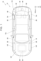
FIG. 1 is a plan view of a vehicle illustrating relative positions of electric units; -
FIG. 2 is a block diagram of the vehicle; -
FIG. 3 is a side view of a vehicle rearward portion; and -
FIG. 4 is a diagram illustrating an internal configuration of a relay unit. - In a first aspect of the present technology, as described above, a vehicle may include a vehicle body, a plurality of wheels that supports the vehicle body, a motor that drives at least one of the wheels, a battery that is electrically connected to the motor, a relay unit electrically connected to the battery, and at least one electric unit electrically connected to the relay unit. The relay unit may include a casing, at least one relay that is disposed inside the casing and that includes a first terminal and a second terminal, a first electric circuit that is disposed inside the casing and that electrically connects the battery to the first terminal of the relay, and a second electric circuit that is disposed inside the casing and that electrically connects the at least one electric unit to the second terminal of the relay. The first electric circuit may be situated further toward an inward side of the vehicle than the second electric circuit, in a right-left direction of the vehicle.
- In a second aspect of the present technology, in addition to the above-described first aspect, the vehicle body may include a wheel well that accommodates one wheel of the wheels. In this case, at least one outside surface of the casing may face the wheel well in the right-left direction of the vehicle. According to such a configuration, in the event of a collision of the vehicle, there is a risk that the wheel well, which has a relatively high rigidity, will come into contact with the relay unit. In this case, the likelihood of the casing of the relay unit being damaged is even higher. However, adopting the present technology enables the effects of damage on the casing on the first electric circuit to be suppressed.
- In a third aspect of the present technology, in addition to the first or second aspect described above, the vehicle body may include a rear compartment situated at a rearward portion of the vehicle body, and the relay unit may be disposed in the rear compartment. Note however, that in another aspect, the relay unit may be disposed in a front compartment situated at a forward portion of the vehicle body, or may be disposed below a floor panel of the vehicle body.
- In a fourth aspect of the present technology, in addition to the above-described third aspect, the rear compartment may include a luggage room. The relay unit may be disposed in the rear compartment, and may be situated below the luggage room. According to such a configuration, even when placement of the relay unit is restricted in a relatively small space, the effects of damage to the casing on the first electric circuit can be suppressed.
- According to a fifth aspect of the present technology, in addition to any one of the first to fourth aspects described above, the relay may be maintained in an open state while the vehicle is travelling. According to such a configuration, even in the event of a collision of the vehicle in which the second electric circuit is externally exposed, for example, the second electric circuit can be reliably disconnected from the battery.
- In a sixth aspect of the present technology, in addition to the fifth aspects described above, the relay may be configured to electrically disconnect the second electric circuit from the battery when the relay is in the open state.
- In a seventh aspect of the present technology, in addition to any one of the first to sixth aspects described above, the at least one electric unit may include a charging inlet to which an external direct current power supply is detachably connected.
- According to an eighth aspect of the present technology, in addition to any one of the first to seventh aspects described above, the vehicle may further include an air conditioning compressor. In this case, the air conditioning compressor may be connected to the first electric circuit of the relay unit. That is to say, the relay unit may have a function of relaying between the battery and the air conditioning compressor.
- According to a ninth aspect of the present technology, in addition to any one of the first to eighth aspects described above, the vehicle may further include an auxiliary battery and a direct current (DC)-to-DC converter. In this case, the auxiliary battery may be connected to the first electric circuit of the relay unit via the DC-to-DC converter. Also, the DC-to-DC converter may be configured to convert direct current electric power from the battery into low-voltage (e.g., 30 volts or lower) direct current electric power that is supplied to the auxiliary battery. That is to say, the relay unit may have a function of relaying between the battery and the auxiliary battery.
- According to a tenth aspect of the present technology, in addition to any one of the first to ninth aspects described above, the vehicle may further include a power feed outlet, and an inverter for power feeding. In this case, the power feed outlet may be connected to the first electric circuit of the relay unit via the inverter. The inverter may also be configured to be capable of converting direct current electric power from the battery into alternating current electric power that is supplied to an outside of the vehicle through the power feed outlet. That is to say, the relay unit may have a function of relaying between the battery and the power feed outlet.
- Hereinafter, representative and non-limiting specific examples of the invention will be described in detail with reference to the drawings. This detailed description is merely intended to provide those skilled in the art with details for carrying out the invention, and is not intended to limit the scope of the invention. Also, additional features and inventions disclosed below can be used separately or in conjunction with other features and inventions to provide further improved vehicles.
- Furthermore, combinations of features and steps disclosed in the following detailed description are not essential for implementing the invention in the broadest sense, but are described only to explain representative embodiments of the invention. Further, the various features of the representative embodiments described above and below, as well as the various features recited in the independent and dependent claims, do not have to be combined in the exact specific embodiment described herein, or in the exact order recited, to provide additional and useful embodiments of the invention.
- All features described in the present specification and/or the claims are intended to be disclosed individually and independently of one another, apart from the configuration of features described in the embodiment and/or claims, as limitations to the original disclosure and particular matters that are claimed. Further, all numerical ranges and group or cluster descriptions are intended to disclose their intermediate configurations as limitations to the original disclosure and particular matters that are claimed.
- A
vehicle 10 according to an embodiment will be described with reference to the drawings. Thevehicle 10 according to the present embodiment is a battery electric vehicle (BEV). However, thevehicle 10 is not limited to a BEV, and may be another type of electrified vehicle, such as a hybrid electric vehicle (HEV) or a plug-in hybrid electric vehicle (PHEV). - Now, in the drawings, a direction FR indicates forward in a front-rear direction of the vehicle, and an opposite direction therefrom indicates rearward in the front-rear direction of the vehicle. Also, a direction LH indicates leftward in a right-left direction (or width direction) of the vehicle, and the opposite direction therefrom indicates rightward in the right-left direction of the vehicle. Moreover, a direction UP indicates an upward direction in an up-down direction of the vehicle, and the opposite direction therefrom indicates a downward direction in the up-down direction of the vehicle. In the present specification, a forward side in the front-rear direction of the vehicle, a rearward side in the front-rear direction of the vehicle, a leftward side in the right-left direction of the vehicle, a rightward side in the right-left direction of the vehicle, an upper side in the up-down direction of the vehicle, and a lower side in the up-down direction of the vehicle may be referred to simply as forward side, rearward side, leftward side, rightward side, upper side, and lower side, respectively.
- As illustrated in
FIGS. 1 and2 , thevehicle 10 includes avehicle body 12 and a plurality of thewheels vehicle body 12 is made of, for example, a metal, such as a steel-based material, an aluminum-based material, or the like. Thewheels vehicle body 12. Thewheels front wheels 14f situated at a forward portion of thevehicle body 12, and a pair ofrear wheels 14r situated at a rearward portion of thevehicle body 12. Thefront wheels 14f are each situated on the right and left of thevehicle body 12. Therear wheels 14r are each situated on the right and left of thevehicle body 12. - An interior of the
vehicle body 12 defines acabin 12c, afront compartment 12f, and arear compartment 12r. Thefront compartment 12f is situated at the forward portion of thevehicle body 12. Therear compartment 12r is situated at the rearward portion of thevehicle body 12. Thecabin 12c is configured to be boardable by occupants. Thecabin 12c is situated between thefront compartment 12f and therear compartment 12r. Thevehicle body 12 has afloor panel 16, adash panel 18, and a plurality ofwheel wells 20. Thefloor panel 16 defines a floor of thecabin 12c. Thedash panel 18 is interposed between thecabin 12c and thefront compartment 12f. Eachwheel well 20 accommodates a corresponding one of thewheels Wheel wells 20 that accommodate thefront wheels 14f are situated at the ends of thefront compartment 12f in the right-left direction.Wheel wells 20 that accommodate therear wheels 14r are situated at the ends of therear compartment 12r in the right-left direction. - As illustrated in
FIG. 3 , aseat 22 for occupants of thevehicle 10 to be seated in is disposed in thecabin 12c. Theseat 22 is a rear seat that is disposed at a rearward portion of thecabin 12c. Therear compartment 12r is situated rearward of theseat 22. A luggage room 12r1 is further defined at an upper portion of therear compartment 12r. Thevehicle body 12 has aluggage floorboard 24 disposed in therear compartment 12r. The luggage floorboard 24 defines a floor of the luggage room 12r1. - As illustrated in
FIGS. 1 to 3 , thevehicle 10 includes abattery unit 26, amotor unit 28, a power control unit (PCU) 30, arelay unit 32, a charginginlet 40, anauxiliary battery 42, a direct current (DC)-to-DC converter 44, anair conditioning compressor 46, acompressor inverter 48, apower feed outlet 50, and apower feed inverter 52. - The
battery unit 26 has acasing 26a, abattery 26b, and a systemmain relay 26c, and is configured to be capable of being charged and discharged. Thecasing 26a accommodates therein thebattery 26b and the systemmain relay 26c. Thebattery 26b has one or more secondary battery cells. The secondary battery cells may be lithium-ion battery cells or all-solid-state battery cells, for example, although not limited thereto in particular. Thebattery unit 26 is disposed under thefloor panel 16. - The
motor unit 28 is electrically connected to thebattery 26b via thePCU 30 and the systemmain relay 26c. Themotor unit 28 is connected to thefront wheels 14f via a speed reducer (omitted from illustration). Themotor unit 28 has a traction motor that drives thefront wheels 14f using electric power supplied from thebattery 26b. Note however, themotor unit 28 is not limited to driving thefront wheels 14f, and it is sufficient to drive at least one of thewheels motor unit 28 may be disposed in thefront compartment 12f. - The
PCU 30 is electrically connected to each of thebattery 26b and themotor unit 28. ThePCU 30 includes an inverter, a converter, and so forth. ThePCU 30 controls supplied electric power between thebattery 26b and themotor unit 28. Alternatively, when thevehicle 10 decelerates, thePCU 30 controls regenerative electric power supplied from themotor unit 28 to thebattery 26b. Note that thePCU 30 may be disposed in thefront compartment 12f and also above themotor unit 28, although not limited thereto in particular. - The
relay unit 32 is electrically connected to thebattery 26b via the systemmain relay 26c. Also, therelay unit 32 is electrically connected to each of a plurality ofelectric units relay unit 32 electrically relays between thebattery 26b and theelectric units electric units inlet 40, a DC-to-DC converter 44, thecompressor inverter 48, and thepower feed inverter 52, although not limited thereto in particular. Therelay unit 32 is disposed inside therear compartment 12r, and more specifically, is disposed below the luggage room 12r1. Therelay unit 32 is disposed between thewheel wells 20 in the right-left direction. More specifically, at least one outer peripheral surface of therelay unit 32 faces awheel well 20. Specifically, therelay unit 32 is closer to the wheel well 20 than the otherelectric units rear compartment 12r. - The charging
inlet 40 is situated at the rearward portion of thevehicle body 12. The charginginlet 40 is connected to an external direct current power supply via acable 2. The charginginlet 40 is configured so that aconnector 4 of thecable 2 is detachably attachable. The external direct current power supply is, for example, a charging station or the like. The charginginlet 40 receives charging electric power from an external direct current power supply to charge thebattery 26b. - The
auxiliary battery 42 has a secondary battery cell and is configured to be capable of being charged and discharged. The rated voltage of theauxiliary battery 42 is approximately 12 volts. Theauxiliary battery 42 is connected to various types of control systems and other accessories of thevehicle 10, and supplies electric power thereto. The secondary battery cells may be lithium-ion battery cells or all-solid-state battery cells, for example, although not limited thereto in particular. Theauxiliary battery 42 is disposed below the luggage room 12r1 of therear compartment 12r. - The DC-to-
DC converter 44 is connected to theauxiliary battery 42. Theauxiliary battery 42 is electrically connected to therelay unit 32 via the DC-to-DC converter 44. The DC-to-DC converter 44 is configured to be able to convert the direct current electric power from thebattery 26b into low-voltage (e.g., 30 volts or lower) direct current electric power to be supplied to theauxiliary battery 42. The DC-to-DC converter 44 is disposed below the luggage room 12r1 of therear compartment 12r. - The
air conditioning compressor 46 is a device that compresses refrigerant gas in an air conditioning heat pump circuit installed in thevehicle 10. Theair conditioning compressor 46 is connected to therelay unit 32 via acompressor inverter 48. Thecompressor inverter 48 is configured to be able to convert direct current electric power from thebattery 26b into alternating current power to be supplied to theair conditioning compressor 46. Thecompressor inverter 48 adjusts the supplied electric power to theair conditioning compressor 46 to control operations of theair conditioning compressor 46. Thecompressor inverter 48 is disposed below the luggage room 12r1 of therear compartment 12r. - The
power feed outlet 50 is configured such that electric equipment can be detachably attached thereto. Thepower feed outlet 50 outputs direct current electric power to the electric equipment. Thepower feed outlet 50 is configured to be capable of high-output power feeding, from 600 watts or more to 1500 watts or less for example, although not limited thereto in particular. Electric equipment referred to here includes, for example, home appliances (such as hair dryers, water boilers, and so forth), personal computers, smartphones, tablet terminals, and the like. Thepower feed outlet 50 is disposed inside thecabin 12c. - The
power feed inverter 52 is connected to thepower feed outlet 50. Thepower feed outlet 50 is connected to therelay unit 32 via thepower feed inverter 52. Thepower feed inverter 52 is configured to be capable of converting direct current electric power from thebattery 26b into alternating current electric power that is supplied to the outside of thevehicle 10 through thepower feed outlet 50. Thepower feed inverter 52 is disposed below the luggage room 12r1 of therear compartment 12r. Here, thepower feed inverter 52 is an example of a "power feeding electric power conversion circuit" in the present technology. - The configuration of the
relay unit 32 will be described in detail with reference toFIGS. 2 and4 . As illustrated inFIG. 2 , therelay unit 32 is electrically connected to thebattery 26b via the systemmain relay 26c and afirst cable 54. Thefirst cable 54 has afirst connector 54a. Thefirst connector 54a is configured to be detachably attachable to therelay unit 32. Therelay unit 32 is connected to the charginginlet 40 via asecond cable 56. Thesecond cable 56 has asecond connector 56a. Thesecond connector 56a is configured to be detachably attachable to therelay unit 32. Therelay unit 32 is connected to the DC-to-DC converter 44 via athird cable 58. Thethird cable 58 has athird connector 58a. Thethird connector 58a is configured to be detachably attachable to therelay unit 32. Therelay unit 32 is connected to thecompressor inverter 48 via afourth cable 60. Thefourth cable 60 has afourth connector 60a. Thefourth connector 60a is configured to be detachably attachable to therelay unit 32. Therelay unit 32 is connected to thepower feed inverter 52 via a fifth cable 62. The fifth cable 62 has afifth connector 62a. Thefifth connector 62a is configured to be detachably attachable to therelay unit 32. - As illustrated in
FIG. 4 , therelay unit 32 has acasing 34. Thecasing 34 is made up of a metal such as an aluminum-based material or the like, for example. Thecasing 34 has a generally cuboid shape, with an upper surface and a lower surface (omitted from illustration) and a front side surface 34s1, a left side surface 34s2, a rear side surface 34s3, and a right side surface 34s4, disposed therebetween. The right side surface 34s4 of thecasing 34 faces the wheel well 20 situated at the right end of thevehicle body 12. Thecasing 34 has afirst connector port 34a, asecond connector port 34b, athird connector port 34c, afourth connector port 34d, and afifth connector port 34e. As an example, thefirst connector port 34a is situated on a front side surface 34s1 of thecasing 34. Thesecond connector port 34b is situated on the rear side surface 34s3 of thecasing 34. Thethird connector port 34c and thefourth connector port 34d are situated on the left side surface 34s2 of thecasing 34. Thefifth connector port 34e is situated on the upper surface of thecasing 34, and is omitted from illustration inFIG. 4 . - As illustrated in
FIGS. 2 and4 , thefirst connector port 34a is configured such that thefirst connector 54a of thefirst cable 54 is detachably attachable thereto, and is electrically connected to thebattery 26b via the systemmain relay 26c and thefirst cable 54. Thesecond connector port 34b is configured such that thesecond connector 56a of thesecond cable 56 is detachably attachable thereto, and is electrically connected to the charginginlet 40 via thesecond cable 56. Thethird connector port 34c is configured such that thethird connector 58a of thethird cable 58 is detachably attachable thereto, and is electrically connected to the DC-to-DC converter 44 via thethird cable 58. Thefourth connector port 34d is configured such that thefourth connector 60a of thefourth cable 60 is detachably attachable thereto, and is electrically connected to thecompressor inverter 48 via thefourth cable 60. Thefifth connector port 34e is configured such that thefifth connector 62a of the fifth cable 62 is detachably attachable thereto, and is electrically connected to thepower feed inverter 52 via the fifth cable 62. - The
relay unit 32 has anelectric circuit unit 35 inside thecasing 34. Theelectric circuit unit 35 has a pair ofrelays 36, a firstelectric circuit 37, and a secondelectric circuit 38. The firstelectric circuit 37 is electrically connected to one end (first terminal) of each of therelays 36, and the secondelectric circuit 38 is electrically connected to the other end (second terminal) of each of therelays 36. That is to say, inside therelay unit 32, the firstelectric circuit 37 is electrically connected to the secondelectric circuit 38 via therelays 36. - The
relays 36 are disposed between the firstelectric circuit 37 and the secondelectric circuit 38. The firstelectric circuit 37 is disposed in a left side portion of thecasing 34, and is situated between therelays 36 and the left side surface 34s2 of thecasing 34 in plan view. The secondelectric circuit 38 is disposed in a right side portion of thecasing 34, and is situated between therelays 36 and the right side surface 34s4 of thecasing 34 in plan view. As a result, in thevehicle 10, the firstelectric circuit 37 is situated further on an inner side of the vehicle in the right-left direction than the secondelectric circuit 38. - The first
electric circuit 37 has a pair ofbus bars 37a connected to thefirst connector port 34a. As described above, thebattery 26b is electrically connected to thefirst connector port 34a via the systemmain relay 26c and thefirst cable 54. When thevehicle 10 is traveling, the systemmain relay 26c is closed, and themotor unit 28 is electrically connected to thebattery 26b. When the systemmain relay 26c is closed, thefirst connector port 34a is electrically connected to thebattery 26b via the systemmain relay 26c. As a result, while thevehicle 10 is traveling, a high voltage is applied to the firstelectric circuit 37 from thebattery 26b, and the firstelectric circuit 37 is maintained in a live state. Accordingly, the firstelectric circuit 37 is electrically connected to thebattery 26b, and also electrically connects thebattery 26b to one end of each of therelays 36. - The first
electric circuit 37 further has a pair ofbus bars 37b connected to thethird connector port 34c. Accordingly, the firstelectric circuit 37 is electrically connected to the DC-to-DC converter 44 via thethird cable 58 that is connected to thethird connector port 34c. The firstelectric circuit 37 further has a pair ofbus bars 37c connected to thefourth connector port 34d. Thus, the firstelectric circuit 37 is electrically connected to thecompressor inverter 48 via thefourth cable 60 that is connected to thefourth connector port 34d. The firstelectric circuit 37 further has a pair ofbus bars 37d connected to thefifth connector port 34e. Accordingly, the firstelectric circuit 37 is electrically connected to thepower feed inverter 52 via the fifth cable 62 that is connected to thefifth connector port 34e. - The second
electric circuit 38 has a pair ofbus bars 38a connected to thesecond connector port 34b. As described above, the charginginlet 40 is electrically connected to thesecond connector port 34b via thesecond cable 56. Accordingly, the secondelectric circuit 38 is electrically connected to the charginginlet 40 and also electrically connects the charginginlet 40 to the other ends of therelays 36. - The
relays 36 are opened and closed by, for example, an electronic control unit (ECU) of thevehicle 10. When therelays 36 are in an open state, the secondelectric circuit 38 is disconnected from the firstelectric circuit 37. When therelays 36 are in a closed state, the secondelectric circuit 38 is electrically connected to the firstelectric circuit 37 and is electrically connected to thebattery 26b. As described above, the charginginlet 40 is electrically connected to the secondelectric circuit 38. Accordingly, when thebattery 26b of thevehicle 10 is being charged, for example, therelays 36 are closed. On the other hand, when thevehicle 10 is traveling, therelays 36 are maintained in an open state. Note that the number ofrelays 36 is not limited to two. The control device may use asingle relay 36 or three ormore relays 36 to control the connection/disconnection of the secondelectric circuit 38 to the firstelectric circuit 37. - In the event of a collision (e.g., a broadside or rear-end collision) of the
vehicle 10 described above, there is a risk that a part of thevehicle body 12, such as the wheel well 20 or the like of thevehicle 10, or another adjacent onboard unit or the like, will come into contact with therelay unit 32. At this time, it is conceivable that thecasing 34 of therelay unit 32 will be damaged, causing the electric circuit inside thecasing 34 to be externally exposed. Thebattery 26b is electrically connected to therelay unit 32, and accordingly even when thecasing 34 is damaged, it is desirable to suppress externally exposing the electric circuit electrically connected to thebattery 26b. - With respect to this point, in the
vehicle 10 of the present embodiment, therelays 36 are provided in therelay unit 32, and the electric circuit in therelay unit 32 is divided into the firstelectric circuit 37 and the secondelectric circuit 38 with therelays 36 as a boundary. The firstelectric circuit 37, which is electrically connected to thebattery 26b, is situated further on the inner side of the vehicle than the secondelectric circuit 38 in the right-left direction. According to this configuration, even when thecasing 34 of therelay unit 32 is damaged from a sideward direction of the vehicle (the right side in the present embodiment), the firstelectric circuit 37 is suppressed from being externally exposed from thecasing 34. On the other hand, although there is a risk that the secondelectric circuit 38 may be externally exposed from thecasing 34, the secondelectric circuit 38 can be electrically disconnected from thebattery 26b by therelays 36. In particular, in thevehicle 10 according to the present embodiment, therelays 36 are maintained in an open state while thevehicle 10 is traveling. Thus, the secondelectric circuit 38 is maintained in a non-live state, and accordingly the safety of thevehicle 10 can be improved even when the secondelectric circuit 38 is exposed due to a collision of thevehicle 10. - In the
vehicle 10 according to the present embodiment, therelay unit 32 is disposed between thewheel wells 20 in the right-left direction. According to this configuration, when a collision (e.g., a right-side broadside collision or a rear-end collision) of thevehicle 10 occurs, there is a risk that the wheel well 20, which has a relatively high rigidity, will come into contact with therelay unit 32. In this case, the likelihood of thecasing 34 of therelay unit 32 being damaged is even higher. However, adopting the present technology enables externally exposing the firstelectric circuit 37 from thecasing 34 to be avoided or suppressed. This reduces the risk of contact between the firstelectric circuit 37, which is applied with a high voltage and is in a live state, and surrounding members or occupants of thevehicle 10, thereby improving the safety of thevehicle 10. - In the
vehicle 10 according to the present embodiment, therelay unit 32 is situated below the luggage room 12r1 in therear compartment 12r. As can be seen fromFIGS. 1 and3 , the space situated below the luggage room 12r1 is narrower than other spaces, and various electric units are disposed inside this space. Even though placement of therelay unit 32 is restricted in such a relatively narrow space, external exposure of the firstelectric circuit 37 from thecasing 34 can be avoided or suppressed. However, the position of therelay unit 32 is not limited to being below the luggage room 12r1 in therear compartment 12r. Therelay unit 32 may be disposed in the luggage room 12r1, may be disposed in thefront compartment 12f, or may be disposed below thefloor panel 16. - In the
vehicle 10 according to the present embodiment, thepower feed outlet 50 is disposed inside thecabin 12c. However, in a modification, the position of thepower feed outlet 50 does not have to be in thecabin 12c, and may be inside the luggage room 12r1. - The charging
inlet 40 according to the present embodiment is an example of "electric unit" according to the present technology. However, the "electric unit" in the present technology, i.e., the electric unit connected to the secondelectric circuit 38, is not limited to being the charginginlet 40, and may be various other types of electric units. In this case, the electric unit may be an electric unit that is not expected to be used while thevehicle 10 is traveling. For example, a power feed outlet disposed in a space other than thecabin 12c (e.g., in the luggage room 12r1) corresponds to an example of an "electric unit" in the present technology when not expected to be used while thevehicle 10 is traveling. Also, in the present embodiment, a collision of a severity in which the secondelectric circuit 38 is exposed from thecasing 34 is exemplified, but the severity of the collision is not limited to this. According to the present technology, effects of a collision on the firstelectric circuit 37 can be reduced regardless of the severity of the collision on thevehicle 10.
Claims (10)
- A vehicle (10) comprising:a vehicle body (12);a plurality of wheels (14f; 14r) that supports the vehicle body (12);a motor (28) that drives at least one of the wheels (14f; 14r);a battery (26b) that is electrically connected to the motor (28);a relay unit (32) that is electrically connected to the battery (26b); andat least one electric unit (40) that is electrically connected to the relay unit (32), whereinthe relay unit (32) includesa casing (34),at least one relay (36) that is disposed inside the casing (34) and that includes a first terminal and a second terminal,a first electric circuit (37) that is disposed inside the casing (34) and that electrically connects the battery (26b) to the first terminal of the relay (36), anda second electric circuit (38) that is disposed inside the casing (34) and that electrically connects the at least one electric unit (40) to the second terminal of the relay (36), andthe first electric circuit (37) is situated further toward an inward side of the vehicle (10) than the second electric circuit (38), in a right-left direction of the vehicle (10).
- The vehicle (10) according to claim 1, whereinthe vehicle body (12) includes a wheel well (20) that accommodates one wheel of the wheels (14f; 14r), andat least one outside surface of the casing (34) faces the wheel well (20) in the right-left direction of the vehicle (10).
- The vehicle (10) according to claim 2, whereinthe vehicle body (12) includes a rear compartment (12r) situated at a rearward portion of the vehicle body (12), andthe relay unit (32) is disposed in the rear compartment (12r).
- The vehicle (10) according to claim 3, whereinthe rear compartment (12r) includes a luggage room (12r1), andthe relay unit (32) is disposed in the rear compartment (12r), and is situated below the luggage room (12r1).
- The vehicle (10) according to any one of claims 1 to 4, wherein the relay (36) is maintained in an open state while the vehicle (10) is travelling.
- The vehicle (10) according to claim 5, wherein the relay (36) is configured to electrically disconnect the second electric circuit (38) from the battery (26b) when the relay (36) is in the open state.
- The vehicle (10) according to any one of claims 1 to 4, wherein the at least one electric unit (40) includes a charging inlet (40) to which an external direct current power supply is detachably connected.
- The vehicle (10) according to claim 1, further comprising an air conditioning compressor (46) that is connected to the first electric circuit (37) of the relay unit (32).
- The vehicle (10) according to claim 1, further comprising:an auxiliary battery (42); anda direct current-to-direct current converter (44), whereinthe auxiliary battery (42) is connected to the first electric circuit (37) of the relay unit (32) via the direct current-to-direct current converter (44), andthe direct current-to-direct current converter (44) is configured to convert direct current electric power from the battery (26b) into low-voltage direct current electric power that is supplied to the auxiliary battery (42).
- The vehicle (10) according to claim 1, further comprising:a power feed outlet (50); andan inverter (52) for power feeding, whereinthe power feed outlet (50) is connected to the first electric circuit (37) of the relay unit (32) via the inverter (52), andthe inverter (52) is configured to convert direct current electric power from the battery (26b) into alternating current electric power that is supplied to an outside of the vehicle (10) through the power feed outlet (50).
Applications Claiming Priority (1)
| Application Number | Priority Date | Filing Date | Title |
|---|---|---|---|
| JP2023217224A JP2025100106A (en) | 2023-12-22 | 2023-12-22 | vehicle |
Publications (1)
| Publication Number | Publication Date |
|---|---|
| EP4574578A1 true EP4574578A1 (en) | 2025-06-25 |
Family
ID=93563313
Family Applications (1)
| Application Number | Title | Priority Date | Filing Date |
|---|---|---|---|
| EP24213205.8A Pending EP4574578A1 (en) | 2023-12-22 | 2024-11-15 | Vehicle |
Country Status (5)
| Country | Link |
|---|---|
| US (1) | US20250206247A1 (en) |
| EP (1) | EP4574578A1 (en) |
| JP (1) | JP2025100106A (en) |
| KR (1) | KR20250098916A (en) |
| CN (1) | CN120191300A (en) |
Citations (5)
| Publication number | Priority date | Publication date | Assignee | Title |
|---|---|---|---|---|
| CN202455130U (en) * | 2011-12-31 | 2012-09-26 | 比亚迪股份有限公司 | Charging/discharging control system of electric vehicle and electric vehicle |
| US20130187449A1 (en) * | 2012-01-24 | 2013-07-25 | Honda Motor Co., Ltd | Vehicle power supply system |
| US20180345820A1 (en) * | 2017-05-31 | 2018-12-06 | Honda Motor Co., Ltd. | Electric vehicle |
| US20190084508A1 (en) * | 2017-09-15 | 2019-03-21 | Honda Motor Co., Ltd. | Vehicle |
| JP2020088934A (en) | 2018-11-16 | 2020-06-04 | 住友電装株式会社 | Electrical junction box |
-
2023
- 2023-12-22 JP JP2023217224A patent/JP2025100106A/en active Pending
-
2024
- 2024-11-12 KR KR1020240160302A patent/KR20250098916A/en active Pending
- 2024-11-13 US US18/946,055 patent/US20250206247A1/en active Pending
- 2024-11-15 CN CN202411630387.9A patent/CN120191300A/en active Pending
- 2024-11-15 EP EP24213205.8A patent/EP4574578A1/en active Pending
Patent Citations (5)
| Publication number | Priority date | Publication date | Assignee | Title |
|---|---|---|---|---|
| CN202455130U (en) * | 2011-12-31 | 2012-09-26 | 比亚迪股份有限公司 | Charging/discharging control system of electric vehicle and electric vehicle |
| US20130187449A1 (en) * | 2012-01-24 | 2013-07-25 | Honda Motor Co., Ltd | Vehicle power supply system |
| US20180345820A1 (en) * | 2017-05-31 | 2018-12-06 | Honda Motor Co., Ltd. | Electric vehicle |
| US20190084508A1 (en) * | 2017-09-15 | 2019-03-21 | Honda Motor Co., Ltd. | Vehicle |
| JP2020088934A (en) | 2018-11-16 | 2020-06-04 | 住友電装株式会社 | Electrical junction box |
Also Published As
| Publication number | Publication date |
|---|---|
| CN120191300A (en) | 2025-06-24 |
| KR20250098916A (en) | 2025-07-01 |
| US20250206247A1 (en) | 2025-06-26 |
| JP2025100106A (en) | 2025-07-03 |
Similar Documents
| Publication | Publication Date | Title |
|---|---|---|
| JP5776852B2 (en) | High-voltage harness connection structure for electric vehicles | |
| US9193269B2 (en) | Vehicle charger mounting structure | |
| CN103534142B (en) | Charging and discharging wiring harness arrangement structure of electric vehicles | |
| EP3514005B1 (en) | Vehicle charging device | |
| US12077049B2 (en) | Vehicle drive unit | |
| CN102514470B (en) | Power storage device | |
| JP2011006050A (en) | Electric component mounting structure for electric vehicle | |
| CN110494320B (en) | Power supply system for vehicle | |
| CN111376742A (en) | Electric automobile | |
| US10559795B1 (en) | Chassis brace for protecting traction battery | |
| CN113386866B (en) | Power control unit | |
| EP4574578A1 (en) | Vehicle | |
| US12115863B2 (en) | Electrified vehicle | |
| CN107150582A (en) | For motor vehicle fuel cell system | |
| JP7345730B2 (en) | Harness arrangement structure | |
| JP7715125B2 (en) | vehicle | |
| EP4610085A1 (en) | Vehicle | |
| EP4707007A1 (en) | Plug-in hybrid electric vehicle | |
| US20250128622A1 (en) | Vehicle | |
| EP4414198A1 (en) | Drive apparatus | |
| KR20260012661A (en) | Electric vehicle | |
| JP2024032269A (en) | vehicle | |
| CN118712606A (en) | Battery pack | |
| JP2023124124A (en) | Control device |
Legal Events
| Date | Code | Title | Description |
|---|---|---|---|
| PUAI | Public reference made under article 153(3) epc to a published international application that has entered the european phase |
Free format text: ORIGINAL CODE: 0009012 |
|
| STAA | Information on the status of an ep patent application or granted ep patent |
Free format text: STATUS: REQUEST FOR EXAMINATION WAS MADE |
|
| 17P | Request for examination filed |
Effective date: 20241115 |
|
| AK | Designated contracting states |
Kind code of ref document: A1 Designated state(s): AL AT BE BG CH CY CZ DE DK EE ES FI FR GB GR HR HU IE IS IT LI LT LU LV MC ME MK MT NL NO PL PT RO RS SE SI SK SM TR |