EP4574576A1 - Bike rack for vehicle - Google Patents
Bike rack for vehicle Download PDFInfo
- Publication number
- EP4574576A1 EP4574576A1 EP24178635.9A EP24178635A EP4574576A1 EP 4574576 A1 EP4574576 A1 EP 4574576A1 EP 24178635 A EP24178635 A EP 24178635A EP 4574576 A1 EP4574576 A1 EP 4574576A1
- Authority
- EP
- European Patent Office
- Prior art keywords
- frame
- plate
- rotating shaft
- limiting
- wheel receiving
- Prior art date
- Legal status (The legal status is an assumption and is not a legal conclusion. Google has not performed a legal analysis and makes no representation as to the accuracy of the status listed.)
- Pending
Links
Images


Classifications
-
- B—PERFORMING OPERATIONS; TRANSPORTING
- B60—VEHICLES IN GENERAL
- B60R—VEHICLES, VEHICLE FITTINGS, OR VEHICLE PARTS, NOT OTHERWISE PROVIDED FOR
- B60R9/00—Supplementary fittings on vehicle exterior for carrying loads, e.g. luggage, sports gear or the like
- B60R9/08—Supplementary fittings on vehicle exterior for carrying loads, e.g. luggage, sports gear or the like specially adapted for sports gear
- B60R9/10—Supplementary fittings on vehicle exterior for carrying loads, e.g. luggage, sports gear or the like specially adapted for sports gear for cycles
-
- B—PERFORMING OPERATIONS; TRANSPORTING
- B60—VEHICLES IN GENERAL
- B60R—VEHICLES, VEHICLE FITTINGS, OR VEHICLE PARTS, NOT OTHERWISE PROVIDED FOR
- B60R9/00—Supplementary fittings on vehicle exterior for carrying loads, e.g. luggage, sports gear or the like
- B60R9/06—Supplementary fittings on vehicle exterior for carrying loads, e.g. luggage, sports gear or the like at vehicle front or rear
Definitions
- the present disclosure relates to the technical field of bike racks, and in particular to a bike rack for a vehicle.
- a bike rack is a device that is mounted at the rear of a vehicle to carry a bike.
- Chinese utility model patent CN219406317U discloses a load rack for a vehicle, including a platform support unit, where the platform support unit is configured to support at least one bike.
- the platform support unit includes at least one wheel receiving member for receiving at least one wheel of the at least one bike, so as to, for example, laterally support the bike.
- the platform support unit further includes at least one bike support arm member, and the at least one bike support arm member is configured to hold and secure the at least one bike when the at least one bike is received by the at least one wheel receiving member.
- the at least one bike support arm member is reconfigurable between a bike support state and a bike loading state.
- the wheel receiving member of the load rack is rotatably connected to the bike support arm member through the same shaft, which requires high strength for the shaft and results in high production costs.
- An objective of the present application is to provide a bike rack for a vehicle, aiming to reduce the requirement for the strength of the rotating shaft and lower the costs.
- a bike rack for a vehicle includes:
- the wheel receiving arm is rotatably connected to the base, allowing the wheel receiving arm to be rotated and folded, reducing the storage volume and saving storage space.
- the support arm is rotatably connected to the base, and the angle of the support arm is adjustable, making it suitable for different sizes of bikes and expanding the scope of application.
- the wheel receiving arm and the support arm are rotatably connected to the base through the rotating rod and the rotating shaft, respectively, so that the wheel receiving arm and the support arm avoid sharing the same shaft, which facilitates the mounting of the wheel receiving arm and the support arm.
- the present application reduces the strength requirements for the rotating rod and the rotating shaft, reduces material usage, simplifies assembly, reduces production costs, facilitates later maintenance and replacement, and improves product competitiveness.
- the sleeve fits with the rotating shaft, making the support arm feature convenient angle adjustment, simple and reliable structure, easy processing, and low cost.
- a wear-resistant sleeve is provided between the sleeve and the rotating shaft; the wear-resistant sleeve is fixedly connected to the rotating shaft; the sleeve is rotatably sleeved on the wear-resistant sleeve; an inner wall of the wear-resistant sleeve is provided with a reinforcing rib; and an end of the wear-resistant sleeve is provided with a radially protruding stop ring.
- the base includes a main frame connected to a vehicle and side frames symmetrically provided on two sides of the main frame; the main frame is rotatably connected to the side frames through a first rotating shaft; the bike rack for the vehicle further includes a bias locking mechanism, and the bias locking mechanism is configured to lock the side frame; the bias locking mechanism is provided on at least one side frame; the bias locking mechanism includes a locking element configured to extend and retract relative to the side frame and a toggle element configured to control the locking element to extend and retract; the locking element is provided at an end of the side frame and protrudes outward; the main frame is provided with a fixing pin that extends outward; the fixing pin fits with the locking element; and the toggle element is connected to the locking element through a transmission assembly.
- the transmission assembly includes a transmission rod and a guide sleeve;
- the guide sleeve includes a first side wall provided at an end of the side frame; a portion of the locking element is provided on the first side wall in a penetrating manner; the locking element is connected to the toggle element through the transmission rod;
- the guide sleeve further includes a second side wall provided in the side frame; the locking element is provided with a connecting rod oriented towards an interior of the side frame; a portion of the connecting rod is provided on the second side wall in a penetrating manner; an end of the connecting rod is connected to the transmission rod;
- a first reset spring is sleeved on the connecting rod; an internal cavity is formed between the first side wall and the second side wall; the first reset spring is provided over the internal cavity; and two ends of the first reset spring respectively abut against the locking element and the second side wall.
- the toggle element and the locking element are respectively provided on two sides of the first rotating shaft;
- the toggle element includes a pedal and a connecting plate;
- the connecting plate is rotatably connected to the side frame through a second rotating shaft;
- the connecting plate is connected to the locking element through the transmission assembly;
- a joint between the connecting plate and the transmission assembly and the pedal are located on two sides of the second rotating shaft, respectively;
- a gap is provided at a bottom of the side frame; a portion of the connecting plate extends into the side frame through the gap; in a reset state of the pedal, a side of the connecting plate abuts against a side of the gap;
- the bottom of the side frame is provided with a mounting port; and the mounting port is communicated with the gap.
- an end of each of the two side frames away from the locking element is provided with a connecting element; the connecting element is configured to connect the two side frames; a second reset spring is provided between the connecting element and the connecting plate; two ends of the second reset spring are connected to the connecting element and the connecting plate, respectively; a reinforcing plate is provided between the two side frames; the reinforcing plate is located on an upper surface of the side frame; the reinforcing plate abuts against the main frame when the locking element fits with the fixing pin; a first limiting rod is provided between the two side frames; and a rotation path of the first limiting rod around the first rotating shaft intersects with the main frame.
- the support arm includes a support frame, an extension frame, and an extension frame locking mechanism; a bottom of the support frame is connected to the base; the extension frame is movably provided on the support frame in a penetrating manner; the extension frame locking mechanism includes a fixed seat and a manual limiting member; the fixed seat is sleeved on the support frame; the manual limiting member is movably connected to the fixed seat; in a first state, the manual limiting member prevents the extension frame from moving up and down relative to the support frame; and in a second state, the extension frame is movable up and down relative to the support frame.
- the extension frame is provided with a fixing strip; a limiting element is provided between the manual limiting member and the fixing strip; the fixing strip is provided with a first limiting groove that fits with the limiting element; the limiting element and the manual limiting member are split structures; the support frame is provided with a first through hole; the limiting element is provided in the first through hole in a penetrating manner; an abutting element is provided between the limiting element and the manual limiting member; the fixed seat is provided with a guide channel; the guide channel is concentric with the first through hole; the abutting element is movably provided on the guide channel in a penetrating manner; and two ends of the abutting element abut against the manual limiting member and the limiting element, respectively.
- a cross-section of the extension frame includes a bottom edge, a top edge, and first side edges symmetrically provided on two sides of the bottom edge; two ends of the bottom edge are respectively connected to bottom ends of the first side edges on the two sides; the first side edges are inclined outward; top ends of the first side edges are connected to the top edge; two sides of the top edge are symmetrically provided with second side edges; two ends of the top edge are respectively connected to bottom ends of the second side edges on the two sides; the second side edges are inclined inward; top ends of the second side edges are respectively connected to the top ends of the first side edges; a highest point of the top edge is lower than the top ends of the first side edges; the top edge is parallel to the bottom edge; the top edge and the second side edges enclose a mounting cavity; and the fixing strip is provided in the mounting cavity.
- the bike rack for a vehicle further includes a sliding push plate; the sliding push plate is configured to connect the wheel receiving arm to a ground; an end of the wheel receiving arm is provided with a receiving cavity; the receiving cavity is provided with a connecting piece; the connecting piece is configured to extend and retract relative to the receiving cavity; the sliding push plate is provided with a connecting structure that fits with the connecting piece; and when the sliding push plate is connected to the wheel receiving arm, the sliding push plate forms a ramp.
- the connecting piece is provided with a second limiting groove and a connecting hook;
- the connecting structure includes a first buckle slot; the first buckle slot is located at an end of the sliding push plate and fits with the connecting hook;
- the receiving cavity is provided with a second limiting rod;
- the second limiting rod is provided on the second limiting groove in a penetrating manner; when a side wall of the second limiting groove away from the connecting hook abuts against the second limiting rod, the connecting hook extends out of the wheel receiving arm; and when a side wall of the second limiting groove adjacent to the connecting hook abuts against the second limiting rod, the connecting hook is received into the wheel receiving arm.
- the sliding push plate includes a push-up plate and at least one extension plate; the push-up plate and an adjacent extension plate are connected by a connecting assembly; the first buckle slot is provided on the push-up plate; the connecting assembly includes a fixing element and a fastening element that fit with each other for locking; the push-up plate is provided with a first mounting hole or mounting slot; the extension plate is provided with second mounting holes; the fixing element is provided on the first mounting hole or mounting slot and the second mounting holes in a penetrating manner; the push-up plate and the extension plate are fixedly connected by the fastening element; the second mounting holes are respectively provided at two ends of the extension plate; and an adjustment slot is provided between the two second mounting holes.
- This embodiment provides a bike rack for a vehicle. As shown in FIGS. 1 , 2 , and 4 , the components of the bike rack for a vehicle are described as follows.
- Wheel receiving arms 1 are configured to receive at least one wheel of at least one bike.
- Support arm 2 is configured to support the bike.
- Base 3 is configured to provide a mounting position for the wheel receiving arms 1 and the support arm 2.
- the wheel receiving arms 1 are provided in pairs on two sides of the base 3, and there is at least one pair of wheel receiving arms.
- the wheel receiving arm 1 is rotatably connected to the base 3 through rotating rod 11.
- the support arm 2 is rotatably connected to the base 3 through rotating shaft 31.
- the support arm 2 includes sleeve 21.
- the rotating shaft 31 is provided on the base 3.
- the sleeve 21 is rotatably sleeved on the rotating shaft 31.
- the wheel receiving arm 1 is rotatably connected to the base 3, allowing the wheel receiving arm 1 to be rotated and folded, reducing the storage volume and saving storage space.
- the support arm 2 is rotatably connected to the base 3, and the angle of the support arm 2 is adjustable, making it suitable for different sizes of bikes and expanding the scope of application.
- the wheel receiving arm 1 and the support arm 2 are rotatably connected to the base 3 through the rotating rod 11 and the rotating shaft 31, respectively. That is, the wheel receiving arm 1 and the support arm 2 avoid sharing the same shaft, which facilitates the mounting of the wheel receiving arm 1 and the support arm 2.
- the present application reduces the strength requirements for the rotating rod 11 and the rotating shaft 31, reduces material usage, simplifies assembly, reduces production costs, facilitates later maintenance and replacement, and improves product competitiveness.
- the sleeve 21 fits with the rotating shaft 31, making the support arm 2 feature convenient angle adjustment, simple and reliable structure, easy processing, and low cost.
- the rotating rod 11 uses a bolt.
- projection of the rotating shaft 31 on a horizontal plane is parallel to projection of the rotating rod 11 on the horizontal plane, such that a rotation direction of the support arm 2 is parallel to a rotation direction of the wheel receiving arm 1.
- the support arm 2 will not collide with the wheel receiving arm 1 during storage, and meanwhile, the support arm 2 will not collide with the bike.
- the number of the support arm 2 is the same as the pair number of the wheel receiving arms 1. Since the number of the support arm 2 is the same as the pair number of the wheel receiving arms 1, each bike is provided with one support arm 2 for fixed support, ensuring the fixation safety of the bike.
- the support arms 2 are provided in a staggered manner along a length direction of the wheel receiving arms 1.
- the two pairs of wheel receiving arms 1 can hold two bikes simultaneously.
- the staggered arrangement of the support arms 2 allows the bikes to be stacked compactly, reducing the space occupied after stacking.
- the base 3 is provided with fixing plate 34 protruding outward, and at least one end of the rotating shaft 31 is fixedly connected to the fixing plate 34 by a bolt.
- the fixing plate 34 is configured to mount and fix the rotating shaft 31, and the fixing plate 34 protrudes outward to facilitate the mounting of the rotating shaft 31.
- the fixing plate 34 is in an inverted U shape, with two open ends of the U shape fixedly connected to the base 3, and a bottom surface of the U shape recessed relative to the open ends.
- the bottom surface of the fixing plate 34 is provided with third through hole 341.
- the rotating shaft 31 is provided with second through hole 311 that fits with the third through hole 341.
- the second through hole 311 and the third through hole 341 are connected by a bolt.
- a threaded plate in a cooperative connection with the bolt is provided between the fixing plate 34 and the base 3.
- the U-shaped fixing plate 34 has high structural strength.
- the bottom surface of the U shape is recessed relative to the open ends, which fits with an outer surface of the rotating shaft 31 to improve the fit between the rotating shaft 31 and the recess.
- the third through hole 341 and the second through hole 311 cooperate to facilitate the connection and fixation between the rotating shaft 31 and the fixing plate 34 by the bolt.
- wear-resistant sleeve 22 is provided between the sleeve 21 and the rotating shaft 31, and the wear-resistant sleeve 22 is connected to the rotating shaft 31 through an elastic cylindrical pin.
- the sleeve 21 is rotatably sleeved on the wear-resistant sleeve 22.
- the wear-resistant sleeve 22 extends the service life of the sleeve 21, and the replacement of the support arm 2 is relatively simple.
- the sleeve 21 and the wear-resistant sleeve 22 are tightly fitted, allowing the support arm 2 to be fixed at any angle.
- the base 3 includes main frame 32 connected to a vehicle and side frames 33 symmetrically provided on two sides of the main frame 32.
- the main frame 32 is rotatably connected to the side frames 33 through first rotating shaft 321.
- the fixing plate 34 is provided on the side frame 33.
- the main frame 32 and the side frames 33 are made of square tubes, which have high strength and low cost.
- the main frame 32 is connected to the vehicle, and a joint structure of the main frame 32 can be designed according to European or American standards.
- the side frames 33 are provided on the two sides of the main frame 32, such that the wheel receiving arms 1 on the two sides are provided on the side frames 33, respectively.
- the design facilitates the mounting of the wheel receiving arms 1, and increases the mounting space, making the mounting convenient.
- the main frame 32 and the side frames 33 are rotatable relative to each other, allowing the main frame 32 to maintain a connected state with the vehicle. By rotating the side frames 33, the bike can be biased, which facilitates opening the trunk of the vehicle.
- the rotating shaft 31 includes first rotating shaft 312 closest to a side of the main frame 32 connected to the vehicle, and second rotating shaft 313 on the other side.
- An end of the first rotating shaft 312 closest to the side of the main frame 32 connected to the vehicle is provided with detachment prevention cover 314, and the other end of the first rotating shaft 312 is fixedly connected to the fixing plate 34 through two bolts.
- the second rotating shaft 313 is provided between two wheel receiving arms 1 on the same side.
- a maximum diameter of the detachment prevention cover 314 is larger than the inner diameter of the sleeve 21 to ensure reliable detachment prevention.
- a side of the first rotating shaft 312 away from the vehicle is connected to the fixing plate 34.
- the detachment prevention cover 314 can prevent the sleeve 21 from detaching from the side of the first rotating shaft 312 adjacent to the vehicle, ensuring reliable mounting of the sleeve 21 on the first rotating shaft 312.
- the first rotating shaft 312 adopts a design with one side extending out, and the side frame 33 does not need to extend to the lower side of the other side of the first rotating shaft 312.
- the design saves material, reduces production costs, and reduces overall volume. Compared to a solution with the two side frames 33 extending out, the main frame 32 is easy to connect with the vehicle.
- two ends of the second rotating shaft 313 are connected to the fixing plate 34 by bolts.
- the two sides of the second rotating shaft 313 are connected to the fixing plate 34 to prevent the sleeve 21 from slipping out.
- the base 3 is provided with shell 35.
- the shell 35 is configured to shield the main frame 32 and the side frames 33, improving the aesthetic appearance.
- the bike rack for a vehicle further includes bias locking mechanism 4.
- the bias locking mechanism 4 is configured to lock the side frame 33.
- the bias locking mechanism 4 is provided on at least one side frame 33.
- the bias locking mechanism 4 includes locking element 41 configured to extend and retract relative to the side frame 33 and toggle element 42 configured to control the locking element 41 to extend and retract.
- the locking element 41 is provided at an end of the side frame 33 and protrudes outward.
- the main frame 32 is provided with fixing pin 322 that extends outward. The fixing pin 322 fits with the locking element 41.
- the toggle element 42 is connected to the locking element 41 through transmission assembly 43.
- the fixing pin 322 is on a rotation path of the locking element 41.
- An upper surface of the side frame 33 is parallel to the horizontal plane.
- the bias locking mechanism 4 is located on the two side frames 33.
- the wheel receiving arms 1 are provided in pairs on the side frames 33 on the two sides. In this embodiment, there are two pairs of wheel receiving arms 1.
- the locking element 41 is pulled and fits with the fixing pin 322 to form a disengaged or clamped state, allowing the side frame 33 to rotate with the wheel receiving arm 1 and the support arm 2 through the first rotating shaft 321.
- the bias locking mechanism 4 is configured to lock the side frame 33 and prevent the wheel receiving arm 1 from biasing when there is no need to open the trunk of the vehicle.
- the locking element 41 fits with the fixing pin 322, achieving a simple structure and reducing production costs.
- the toggle element 42 directly drives the locking element 41 through the transmission assembly 43, achieving simple control.
- the action of the toggle element 42 is transmitted to the locking element 41 through the transmission assembly 43.
- the locking element 41 retracts into the side frame 33, and the locking element 41 separates from the fixing pin 322, achieving an unlocking purpose and allowing the side frame 33 to rotate.
- an end of the side frame 33 away from the vehicle can be tilted, with one end downward and the other end upward, manually or through a bike weight, thereby achieving a tilting purpose and biasing the bike.
- the transmission assembly 43 includes transmission rod 431 and guide sleeve 432.
- the guide sleeve 432 includes first side wall 433 provided at an end of the side frame 33. A portion of the locking element 41 is provided on the first side wall 433 in a penetrating manner.
- the locking element 41 is connected to the toggle element 42 through the transmission rod 431. Through the connection of the transmission rod 431, the pushing and pulling forces of the toggle element 42 are transmitted to the locking element 41, ensuring reliable transmission.
- the guide sleeve 432 improves the strength of the end of the side frame 33.
- the first side wall 433 plays a role in blocking the end of the side frame 33, preventing external substances from entering the interior of the side frame 33 and improving the protection. Meanwhile, it also plays a role of guiding the extension and retraction of the locking element 41. Therefore, the guide sleeve 432 is easy to replace after wear, with low maintenance costs.
- the guide sleeve 432 further includes second side wall 434 provided in the side frame 33.
- the locking element 41 is provided with connecting rod 411 oriented towards an interior of the side frame 33.
- a portion of the connecting rod 411 is provided on the second side wall 434 in a penetrating manner.
- An end of the connecting rod 411 is connected to the transmission rod 431.
- the second side wall 434 enhances the internal strength of the side frame 33 and also serves as a guide for the connecting rod 411, ensuring reliable movement of the locking element 41.
- first reset spring 412 is sleeved on the connecting rod 411.
- Internal cavity 435 is formed between the first side wall 433 and the second side wall 434.
- the first reset spring 412 is provided over the internal cavity 435. Two ends of the first reset spring 412 respectively abut against the locking element 41 and the second side wall 434. Through the first reset spring 412, the locking element 41 has a tendency to extend outward, ensuring reliable cooperation between the locking element 41 and the fixing pin 322.
- the toggle element 42 and the locking element 41 are respectively provided on two sides of the first rotating shaft 321.
- the toggle element 42 and the locking element 41 are arranged opposite each other on the two sides of the first rotating shaft 321.
- the locking element 41 retracts, and one side of the locking element 41 tilts and biases.
- the design achieves smooth biasing and easy use.
- the toggle element 42 includes pedal 421 and connecting plate 422.
- the connecting plate 422 is rotatably connected to the side frame 33 through second rotating shaft 423.
- the connecting plate 422 is connected to the locking element 41 through transmission assembly 43.
- a joint between the connecting plate 422 and the transmission assembly 43 and the pedal 421 are located on two sides of the second rotating shaft 423, respectively.
- the pedal 421 is convenient for stepping on. Compared to a solution of using hands, stepping on the pedal 421 with feet is more energy-efficient.
- the pedal 421 can be replaced by a pull rod, etc.
- the connecting plate 422 is configured to drive the transmission assembly 43.
- the pedal 421 and the joint between the connecting plate 422 and the transmission assembly 43 are located opposite each other on the two sides of the second rotating shaft 423, such that when stepping on the pedal 421, the connecting plate 422 rotates relatively, thereby pulling the transmission assembly 43.
- gap 332 is provided at a bottom of the side frame 33.
- a portion of the connecting plate 422 extends into the side frame 33 through the gap 332.
- a side of the connecting plate 422 abuts against a side of the gap 332.
- the gap 332 is provided for the connecting plate 422 to extend into the side frame 33, and plays a role in limiting the connecting plate 422, ensuring reliable resetting of the connecting plate 422.
- the bottom of the side frame 33 is provided with mounting port 333.
- the mounting port 333 is communicated with the gap 332.
- the mounting port 333 is provided for the observation and maintenance of an internal component of the side frame 33.
- connecting element 335 is configured to connect the two side frames 33.
- the connecting element 335 enables synchronous movement between the two side frames 33 and improves the overall strength of the base 3.
- second reset spring 424 is provided between the connecting element 335 and the connecting plate 422. Two ends of the second reset spring 424 are connected to the connecting element 335 and the connecting plate 422, respectively.
- hook 3351 is provided below the connecting element 335, and one end of the second reset spring 424 is connected to the hook 3351.
- the second reset spring 424 allows the connecting plate 422 to have a tendency to push towards the locking element 41, ensuring reliable cooperation between the locking element 41 and the fixing pin 322 and ensuring reliable resetting of the pedal 421.
- the transmission rod 431 includes U-shaped elements 4311 at two ends and connecting rod 4312 connecting the U-shaped elements 4311 at the two ends.
- An end of the connecting rod 411 is provided in a groove of the U-shaped element 4311 and connected to the U-shaped element 4311.
- a portion of the connecting plate 422 is provided in the groove of the U-shaped element 4311 and connected to the U-shaped element 4311.
- the locking element 41 includes bevel surface 413 and fixing groove 414 that fits with the fixing pin 322.
- the fixing groove 414 is provided with a curved surface.
- the bevel surface 413 is provided directly below the fixing groove 414.
- a lower end of the bevel surface 413 is converged towards an interior of the side frame 33.
- the bevel surface 413 facilitates the cooperation between the fixing pin 322 and the bevel surface 413 when the side frame 33 is reset, allowing the locking element 41 to retract.
- the curved surface of the fixing groove 414 can be well matched with the fixing pin 322.
- reinforcing plate 334 is provided between the two side frames 33.
- the reinforcing plate 334 is provided on the upper surface of the side frame 33. The reinforcing plate 334 enables the synchronous movement between the two side frames 33 and improves the overall strength of the base 3.
- the reinforcing plate 334 abuts against the main frame 32 when the locking element 41 fits with the fixing pin 322, preventing the side frame 33 from rotating beyond a range during resetting.
- first limiting rod 336 is provided between the two side frames 33.
- a rotation path of the first limiting rod 336 around the first rotating shaft 321 intersects with the main frame 32.
- the first limiting rod 336 abuts against the main frame 32 when the side frame 33 rotates in place, thereby limiting further rotation of the side frame 33 and preventing the side frame 33 from rotating beyond its range.
- the side frame 33 is provided with mounting base 337.
- the mounting base 337 is provided with support surface 3371.
- the wheel receiving arm 1 includes protective shell 13 and bracket 14.
- the protective shell 13 is sleeved outside the bracket 14.
- the bracket 14 is provided with support element 141.
- the support element 141 is provided with first surface 1411 facing the side frame 33 and second surface 1412 adjacent to the first surface 1411.
- the second surface 1412 is below the first surface 1411, and the first surface 1411 and the second surface 1412 form a circular arc transition.
- the second surface 1412 is in contact with the support surface 3371.
- the mounting base 337 is rotatably connected to the bracket 14.
- the support surface 3371 can abut against the second surface 1412, allowing the wheel receiving arm 1 to be in the unfolded state.
- the circular arc transition between the first surface 1411 and the second surface 1412 prevents the support element 141 from colliding with the support surface 3371 during rotation.
- the mounting base 337 includes bottom plate 3372 and side plates 3373 provided on two sides of the bottom plate 3372.
- One side of the side plate 3373 is fixedly connected to an outer surface of the side frame 33.
- the bottom plate 3372 is lower than a lower surface of the side frame 33.
- the bottom plate 3372 and side plates 3373 of the mounting base 337 form a reliable U-shaped structure.
- the bottom plate 3372 is lower than the lower surface of the side frame 33, leaving a gap between the bottom plate 3372 and the lower surface of the side frame 33, which facilitates the removal of dirt and prevents the accumulation of dirt, dust, etc.
- the limiting element 253 and the manual limiting member 252 are split structures, which is convenient for assembly, reduces the accuracy requirements for production and assembly, and reduces production costs.
- top sleeve 26 is provided at a top end of the extension frame 24.
- the top sleeve 26 is connected to the top end of the extension frame 24, and it can be sleeved on the top end of the extension frame 24.
- the top sleeve 26 can cover the top end of the extension frame 24 so as to prevent a cross-section of the extension frame 24 from scratching a user or the bike, improving safety.
- An outer diameter of the top sleeve 26 is not less than an outer diameter of the support frame 23 so as to prevent the extension frame 24 from fully retracting into the support frame 23, ensuring reliable use of the extension frame 24.
- the top sleeve 26 is provided with strap locking device 27.
- the strap locking device 27 is provided with downward extending strap 271.
- the strap 271 is configured to bind the bike.
- the strap locking device 27 is provided with second throughslot 272 for accommodating the strap 271.
- the strap 271 passes through the second throughslot 272 to form encirclement with the strap locking device 27, so as to fix a portion of the bike in the encirclement.
- the strap locking device 27 can also serve as a handle for dragging the extension frame 24.
- the strap locking device 27 is provided with ratchet buckle 273.
- the ratchet buckle 273 is rotatably connected to the strap locking device 27.
- the ratchet buckle 273 has a tendency to move towards the locking strap 271, which can be achieved by a torsion spring or a reset spring.
- the strap 271 is provided with second buckle slots 2711 that fit with the ratchet buckle 273. There are multiple second buckle slots 2711 provided for easy adjustment.
- the ratchet buckle 273 fits with the strap 271 to allow the strap 271 to enter freely. Withdrawing the strap 271 will be blocked by the ratchet buckle 273, ensuring the binding safety and reliability of the bike.
- the ratchet buckle 273 includes buckle teeth 2731 and trigger 2732.
- the buckle teeth 2731 and the trigger 2732 are respectively provided on two sides of a rotation center of the ratchet buckle 273.
- the buckle teeth 2731 fit with the second buckle slots 2711 to ensure reliable fixation.
- the trigger 2732 is configured to separate the buckle teeth 2731 from the second buckle slots 2711, allowing the strap 271 to be withdrawn.
- the strap locking device 27 is provided with support pad 274.
- the support pad 274 abuts against the bike.
- the support pad 274 is made of a soft material to prevent damage to the bike during a collision.
- sleeve pipe 232 is sleeved on the support frame 23.
- the sleeve pipe 232 is provided with first throughslot 233 for accommodating the strap 271.
- the first throughslot 233 is configured to store the strap 271 at ordinary times, thereby preventing the strap 271 from fluttering.
- the strap locking device 27, the top sleeve 26, the extension frame 24, and the fixing strip 241 are fixedly connected by the same bolt, and are all fixed to the extension frame 24, providing good stress resistance and reliable structure.
- the cross-section of the extension frame 24 includes bottom edge 242, top edge 243, and first side edges 244 symmetrically provided on two sides of the bottom edge 242. Two ends of the bottom edge 242 are respectively connected to bottom ends of the first side edges 244 on the two sides. The first side edges 244 are inclined outward. Top ends of the first side edges 244 are connected to the top edge 243. Two sides of the top edge 243 are symmetrically provided with second side edges 245. Two ends of the top edge 243 are respectively connected to bottom ends of the second side edges 245 on the two sides. The second side edges 245 are inclined inward.
- Top ends of the second side edges 245 are respectively connected to the top ends of the first side edges 244.
- a highest point of the top edge 243 is lower than the top ends of the first side edges 244.
- the top edge 243 is parallel to the bottom edge 242.
- the bottom edge 242, the top edge 243, and the first side edges 244 form a circle with a high structural strength.
- the top edge 243 is lower than the top ends of the first side edges 244, making the top edge 243 concave and improving the structural strength.
- the top edge 243 and the second side edges 245 enclose mounting cavity 246.
- the fixing strip 241 is provided in the mounting cavity 246.
- the mounting cavity 246 is provided with a large bottom surface and a small opening. Once the fixing strip 241 is inserted from one side, it cannot be removed from the opening, and its mounting and fixation is completed when the upper end is connected to the extension frame 24 by a bolt.
- the design is simple, convenient, and reliable.
- a cross-section of the support frame 23 is concave, which provides higher overall strength compared to a simple rectangular shape.
- the bike rack for a vehicle further includes sliding push plate 5.
- the sliding push plate 5 is configured to connect the wheel receiving arm 1 to a ground.
- An end of the wheel receiving arm 1 is provided with receiving cavity 12.
- the receiving cavity 12 is provided with connecting piece 6.
- the connecting piece 6 is configured to extend and retract relative to the receiving cavity 12.
- the sliding push plate 5 is provided with a connecting structure that fits with the connecting piece 6. When the sliding push plate 5 is connected to the wheel receiving arm 1, the sliding push plate 5 forms a ramp.
- the sliding push plate 5 is mounted when needed and disassembled after use, reducing the usual space occupation.
- the connecting piece 6 adopts a telescopic design, and can be hidden when not in use, with an attractive appearance and preventing the entry of external dust, dirt, etc.
- the sliding push plate 5 is connected to the wheel receiving arm 1 to form a ramp, which facilitates the pushing of the bike from the ground along the ramp onto the wheel receiving arm 1, making it convenient and labor-saving to load and unload the bike.
- the connecting piece 6 is provided with second limiting groove 61 and connecting hook 62.
- the connecting structure includes first buckle slot 51.
- the first buckle slot 51 is located at an end of the sliding push plate 5.
- the first buckle slot 51 fits with the connecting hook 62.
- the receiving cavity 12 is provided with second limiting rod 121.
- the second limiting rod 121 is provided on the second limiting groove 61 in a penetrating manner. When a side wall of the second limiting groove 61 away from the connecting hook 62 abuts against the second limiting rod 121, the connecting hook 62 extends out of the wheel receiving arm 1.
- the connecting hook 62 fits with the first buckle slot 51. It is only necessary to buckle the first buckle slot 51 onto the connecting hook 62 to complete the connection and fixation between the wheel receiving arm 1 and the sliding push plate 5. It is only necessary to pick up the sliding push plate 5 and disengage the first buckle slot 51 from the connecting hook 62, thereby completing a disassembling purpose.
- the design is simple and convenient to use.
- the second limiting groove 61 fits with the second limiting rod 121 to limit the movement of the connecting piece 6 and prevent the connecting piece 6 from escaping.
- an outer surface of the connecting piece 6 that contacts the receiving cavity 12 is provided with boss 63.
- the boss 63 reduces a contact area between each surface of the connecting piece 6 and an inner wall of the receiving cavity 12, reducing sliding friction and allowing the connecting piece 6 to move smoothly.
- a top surface of the connecting piece 6 is provided with upper buckles 65.
- the upper buckles 65 reduce friction with the inner wall of the receiving cavity 12. Meanwhile, the upper buckles 65 tilt upward to abut against the inner wall of the receiving cavity 12, preventing the connecting piece 6 from shaking and sliding freely inside.
- the connecting hook 62 is provided with reinforcing strip 64.
- the bracket 14 is a square tube.
- the receiving cavity 12 is provided on the bracket 14.
- a hollow cavity of the square tube forms the receiving cavity 12.
- the protective shell 13 is configured to improve protection and provide more space for placing the bike.
- the bracket 14 is configured to provide support and carry the weight of the bike.
- the receiving cavity 12 is provided on the bracket 14, allowing a stress on the connecting piece 6 to be directly transmitted to the bracket 14, resulting in good load-bearing performance.
- the protective shell 13 is provided with inwardly recessed arc-shaped groove 131.
- the arc-shaped groove 131 is located directly below the connecting piece 6.
- the arc-shaped groove 131 allows the user to extend a finger to a lower side of the connecting piece 6, facilitating the movement of the connecting piece 6 by the user.
- the bracket 14 is provided with an arc-shaped gap 142.
- the arc-shaped gap 142 is located between the arc-shaped groove 131 and the connecting piece 6.
- the arc-shaped gap 142 allows the user to directly touch the connecting piece 6 after extending the finger to the lower side of the connecting piece 6, facilitating the movement of the connecting piece 6 by the user.
- a bottom of the connecting hook 62 is provided with lower buckle 621.
- the lower buckle 621 abuts against a bottom surface of the receiving cavity 12.
- the connecting hook 62 is received in the wheel receiving arm 1, the lower buckle 621 is unlocked or locked by pressing it upward from the arc-shaped groove 131.
- One side of the lower buckle 621 is connected to the connecting hook 62, while the other three sides thereof are suspended, making it easy to press and deform the lower buckle 621.
- the bottom of the connecting hook 62 is provided with downwardly extending pull plate 622.
- the pull plate 622 facilitates the user to pull and move the connecting piece 6.
- the sliding push plate 5 includes push-up plate 52 and at least one extension plate 53.
- the push-up plate 52 and the adjacent extension plate 53 are connected by connecting assembly 54.
- the first buckle slot 51 is provided on the push-up plate 52.
- the push-up plate 52 is connected to the connecting piece 6.
- the number of the extension plates 53 is adjustable according to needs.
- the connecting assembly 54 includes fixing element 541 and fastening element 542 that fit with each other for locking.
- the push-up plate 52 is provided with a first mounting hole or mounting slot 521.
- the extension plate 53 is provided with second mounting holes 531.
- the fixing element 541 is provided on the first mounting hole or mounting slot 521 and the second mounting holes 531 in a penetrating manner, and the push-up plate 52 and the extension plate 53 are fixedly connected by the fastening element 542.
- the push-up plate 52 is provided with the mounting slot 521, and the fastening element 542 is a straight knob.
- the fastening element 542 can also be a nut, etc.
- the fixing element 541 is a half-round-head square-neck screw.
- the first mounting hole and the second mounting holes 531 are square holes.
- the half-round-head square-neck screw fits with the square holes to prevent the half-round-head square-neck screw from rotating, making it easy to rotate the straight knob.
- the mounting slot 521 is provided along a length direction of the push-up plate 52.
- the mounting slot 521 fits with the second mounting holes 531 to achieve a length adjustment function between the push-up plate 52 and the extension plate 53.
- the second mounting holes 531 are respectively provided at two ends of the extension plate 53. Adjustment slot 532 is provided between the two second mounting holes 531. The adjustment slot 532 is provided along a length direction of the extension plate 53. The adjustment slot 532 allows for the mounting length adjustment between extension plates 53.
- the second mounting hole 531 of upper extension plate 53 is aligned with the adjustment slot 532 of lower extension plate 53, positioning the connecting assembly 54 in a middle of the two extension plates 53. This facilitates the loosening of the fastening element 542 for length adjustment, thereby achieving the length adjustment function of the sliding push plate 5.
- linkage 15 is provided between the adjacent wheel receiving arms 1 on the same side.
- the linkage 15 is fixedly connected to the wheel receiving arms 1 through second limiting rod 121.
- the second limiting rod 121 is provided on the bracket 14 in a penetrating manner and extends out of the bracket 14 at two ends.
- the second limiting rod 121 is configured to limit and fix the linkage 15.
- the second limiting rod 121 uses a bolt, and there are two pairs of wheel receiving arms 1.
- the linkage 15 enables the wheel receiving arms 1 on the same side to rotate synchronously, enhancing the overall strength of the bike rack for a vehicle.
- This embodiment provides a bike rack for a vehicle.
- this embodiment except that there are three pairs of wheel receiving arms 1, other features are the same as those of Embodiment 1.
Landscapes
- Engineering & Computer Science (AREA)
- Mechanical Engineering (AREA)
- Fittings On The Vehicle Exterior For Carrying Loads, And Devices For Holding Or Mounting Articles (AREA)
- Motorcycle And Bicycle Frame (AREA)
Abstract
Description
- The present disclosure relates to the technical field of bike racks, and in particular to a bike rack for a vehicle.
- A bike rack is a device that is mounted at the rear of a vehicle to carry a bike.
- In the prior art, Chinese utility model patent
CN219406317U discloses a load rack for a vehicle, including a platform support unit, where the platform support unit is configured to support at least one bike. The platform support unit includes at least one wheel receiving member for receiving at least one wheel of the at least one bike, so as to, for example, laterally support the bike. The platform support unit further includes at least one bike support arm member, and the at least one bike support arm member is configured to hold and secure the at least one bike when the at least one bike is received by the at least one wheel receiving member. The at least one bike support arm member is reconfigurable between a bike support state and a bike loading state. However, the wheel receiving member of the load rack is rotatably connected to the bike support arm member through the same shaft, which requires high strength for the shaft and results in high production costs. - An objective of the present application is to provide a bike rack for a vehicle, aiming to reduce the requirement for the strength of the rotating shaft and lower the costs.
- The present disclosure adopts the following technical solution. A bike rack for a vehicle includes:
- wheel receiving arms, configured to receive at least one wheel of at least one bike;
- a support arm, configured to support the bike; and
- a base, configured to provide a mounting position for the wheel receiving arms and the support arm; and
- where, the wheel receiving arms are provided in pairs on two sides of the base, and there is at least one pair of wheel receiving arms; the wheel receiving arms each are rotatably connected to the base through a rotating rod; the support arm is rotatably connected to the base through a rotating shaft, and the support arm includes a sleeve; the rotating shaft is provided on the base; and the sleeve is rotatably sleeved on the rotating shaft.
- Compared to the prior art, the present application has the following advantages. The wheel receiving arm is rotatably connected to the base, allowing the wheel receiving arm to be rotated and folded, reducing the storage volume and saving storage space. The support arm is rotatably connected to the base, and the angle of the support arm is adjustable, making it suitable for different sizes of bikes and expanding the scope of application. The wheel receiving arm and the support arm are rotatably connected to the base through the rotating rod and the rotating shaft, respectively, so that the wheel receiving arm and the support arm avoid sharing the same shaft, which facilitates the mounting of the wheel receiving arm and the support arm. Compared to a solution of sharing the same shaft, the present application reduces the strength requirements for the rotating rod and the rotating shaft, reduces material usage, simplifies assembly, reduces production costs, facilitates later maintenance and replacement, and improves product competitiveness. The sleeve fits with the rotating shaft, making the support arm feature convenient angle adjustment, simple and reliable structure, easy processing, and low cost.
- In some embodiments of the present application, a wear-resistant sleeve is provided between the sleeve and the rotating shaft; the wear-resistant sleeve is fixedly connected to the rotating shaft; the sleeve is rotatably sleeved on the wear-resistant sleeve; an inner wall of the wear-resistant sleeve is provided with a reinforcing rib; and an end of the wear-resistant sleeve is provided with a radially protruding stop ring.
- In some embodiments of the present application, the base includes a main frame connected to a vehicle and side frames symmetrically provided on two sides of the main frame; the main frame is rotatably connected to the side frames through a first rotating shaft; the bike rack for the vehicle further includes a bias locking mechanism, and the bias locking mechanism is configured to lock the side frame; the bias locking mechanism is provided on at least one side frame; the bias locking mechanism includes a locking element configured to extend and retract relative to the side frame and a toggle element configured to control the locking element to extend and retract; the locking element is provided at an end of the side frame and protrudes outward; the main frame is provided with a fixing pin that extends outward; the fixing pin fits with the locking element; and the toggle element is connected to the locking element through a transmission assembly.
- Further, the transmission assembly includes a transmission rod and a guide sleeve; the guide sleeve includes a first side wall provided at an end of the side frame; a portion of the locking element is provided on the first side wall in a penetrating manner; the locking element is connected to the toggle element through the transmission rod; the guide sleeve further includes a second side wall provided in the side frame; the locking element is provided with a connecting rod oriented towards an interior of the side frame; a portion of the connecting rod is provided on the second side wall in a penetrating manner; an end of the connecting rod is connected to the transmission rod; a first reset spring is sleeved on the connecting rod; an internal cavity is formed between the first side wall and the second side wall; the first reset spring is provided over the internal cavity; and two ends of the first reset spring respectively abut against the locking element and the second side wall.
- Further, the toggle element and the locking element are respectively provided on two sides of the first rotating shaft; the toggle element includes a pedal and a connecting plate; the connecting plate is rotatably connected to the side frame through a second rotating shaft; the connecting plate is connected to the locking element through the transmission assembly; a joint between the connecting plate and the transmission assembly and the pedal are located on two sides of the second rotating shaft, respectively; a gap is provided at a bottom of the side frame; a portion of the connecting plate extends into the side frame through the gap; in a reset state of the pedal, a side of the connecting plate abuts against a side of the gap; the bottom of the side frame is provided with a mounting port; and the mounting port is communicated with the gap.
- Further, an end of each of the two side frames away from the locking element is provided with a connecting element; the connecting element is configured to connect the two side frames; a second reset spring is provided between the connecting element and the connecting plate; two ends of the second reset spring are connected to the connecting element and the connecting plate, respectively; a reinforcing plate is provided between the two side frames; the reinforcing plate is located on an upper surface of the side frame; the reinforcing plate abuts against the main frame when the locking element fits with the fixing pin; a first limiting rod is provided between the two side frames; and a rotation path of the first limiting rod around the first rotating shaft intersects with the main frame.
- In some embodiments of the present application, the support arm includes a support frame, an extension frame, and an extension frame locking mechanism; a bottom of the support frame is connected to the base; the extension frame is movably provided on the support frame in a penetrating manner; the extension frame locking mechanism includes a fixed seat and a manual limiting member; the fixed seat is sleeved on the support frame; the manual limiting member is movably connected to the fixed seat; in a first state, the manual limiting member prevents the extension frame from moving up and down relative to the support frame; and in a second state, the extension frame is movable up and down relative to the support frame.
- Further, the extension frame is provided with a fixing strip; a limiting element is provided between the manual limiting member and the fixing strip; the fixing strip is provided with a first limiting groove that fits with the limiting element; the limiting element and the manual limiting member are split structures; the support frame is provided with a first through hole; the limiting element is provided in the first through hole in a penetrating manner; an abutting element is provided between the limiting element and the manual limiting member; the fixed seat is provided with a guide channel; the guide channel is concentric with the first through hole; the abutting element is movably provided on the guide channel in a penetrating manner; and two ends of the abutting element abut against the manual limiting member and the limiting element, respectively.
- Further, a cross-section of the extension frame includes a bottom edge, a top edge, and first side edges symmetrically provided on two sides of the bottom edge; two ends of the bottom edge are respectively connected to bottom ends of the first side edges on the two sides; the first side edges are inclined outward; top ends of the first side edges are connected to the top edge; two sides of the top edge are symmetrically provided with second side edges; two ends of the top edge are respectively connected to bottom ends of the second side edges on the two sides; the second side edges are inclined inward; top ends of the second side edges are respectively connected to the top ends of the first side edges; a highest point of the top edge is lower than the top ends of the first side edges; the top edge is parallel to the bottom edge; the top edge and the second side edges enclose a mounting cavity; and the fixing strip is provided in the mounting cavity.
- In some embodiments of the present application, the bike rack for a vehicle further includes a sliding push plate; the sliding push plate is configured to connect the wheel receiving arm to a ground; an end of the wheel receiving arm is provided with a receiving cavity; the receiving cavity is provided with a connecting piece; the connecting piece is configured to extend and retract relative to the receiving cavity; the sliding push plate is provided with a connecting structure that fits with the connecting piece; and when the sliding push plate is connected to the wheel receiving arm, the sliding push plate forms a ramp.
- Further, the connecting piece is provided with a second limiting groove and a connecting hook; the connecting structure includes a first buckle slot; the first buckle slot is located at an end of the sliding push plate and fits with the connecting hook; the receiving cavity is provided with a second limiting rod; the second limiting rod is provided on the second limiting groove in a penetrating manner; when a side wall of the second limiting groove away from the connecting hook abuts against the second limiting rod, the connecting hook extends out of the wheel receiving arm; and when a side wall of the second limiting groove adjacent to the connecting hook abuts against the second limiting rod, the connecting hook is received into the wheel receiving arm.
- Further, the sliding push plate includes a push-up plate and at least one extension plate; the push-up plate and an adjacent extension plate are connected by a connecting assembly; the first buckle slot is provided on the push-up plate; the connecting assembly includes a fixing element and a fastening element that fit with each other for locking; the push-up plate is provided with a first mounting hole or mounting slot; the extension plate is provided with second mounting holes; the fixing element is provided on the first mounting hole or mounting slot and the second mounting holes in a penetrating manner; the push-up plate and the extension plate are fixedly connected by the fastening element; the second mounting holes are respectively provided at two ends of the extension plate; and an adjustment slot is provided between the two second mounting holes.
-
-
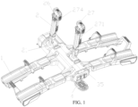
FIG. 1 is a first structural diagram of a bike rack for a vehicle according toEmbodiment 1 of the present disclosure; -
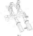
FIG. 2 is a first structural diagram of the bike rack for a vehicle with a shell removed according toEmbodiment 1 of the present disclosure; -
FIG. 3 is an exploded view of a sleeve mounting structure of the bike rack for a vehicle according toEmbodiment 1 of the present disclosure; -
FIG. 4 is a detail of A shown inFIG. 2 ; -
FIG. 5 is a structural diagram of a wear-resistant sleeve of the bike rack for a vehicle according toEmbodiment 1 of the present disclosure; -
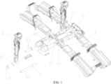
FIG. 6 is a second structural diagram of the bike rack for a vehicle according toEmbodiment 1 of the present disclosure; -
FIG. 7 is a second structural diagram of the bike rack for a vehicle with the shell removed according toEmbodiment 1 of the present disclosure; -
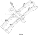
FIG. 8 is a top view of the bike rack for a vehicle according to Embodiment 1 of the present disclosure; -
FIG. 9 is a section view, taken along B-B after rotation, of the bike rack for a vehicle shown inFIG. 8 ; -
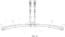
FIG. 10 is a section view, taken along C-C after rotation, of the bike rack for a vehicle shown inFIG. 8 ; -
FIG. 11 is a detail of D shown inFIG. 9 ; -
FIG. 12 is a detail of E shown inFIG. 9 ; -
FIG. 13 is a detail of F shown inFIG. 6 ; -
FIG. 14 is a detail of G shown inFIG. 6 ; -
FIG. 15 is a detail of H shown inFIG. 10 ; -
FIG. 16 is a structural diagram of a locking element of the bike rack for a vehicle according toEmbodiment 1 of the present disclosure; -
FIG. 17 is a detail of J shown inFIG. 9 ; -
FIG. 18 is a detail of K shown inFIG. 9 ; -
FIG. 19 is a detail of L shown inFIG. 9 ; -
FIG. 20 is a structural diagram of an extension frame of the bike rack for a vehicle according toEmbodiment 1 of the present disclosure; -
FIG. 21 is a structural diagram of a support frame of the bike rack for a vehicle according toEmbodiment 1 of the present disclosure; -
FIG. 22 is a structural diagram of the bike rack for a vehicle with a sliding push plate assembled according toEmbodiment 1 of the present disclosure; -
FIG. 23 is a section view of the bike rack for a vehicle with the sliding push plate assembled according toEmbodiment 1 of the present disclosure; -
FIG. 24 is a third structural diagram of the bike rack for a vehicle according toEmbodiment 1 of the present disclosure; -
FIG. 25 is a first structural diagram of a connecting piece of the bike rack for a vehicle according toEmbodiment 1 of the present disclosure; -
FIG. 26 is a second structural diagram of the connecting piece of the bike rack for a vehicle according toEmbodiment 1 of the present disclosure; -
FIG. 27 is a structural diagram of the sliding push plate of the bike rack for a vehicle according toEmbodiment 1 of the present disclosure; -
FIG. 28 is a detail of M shown inFIG. 23 ; -
FIG. 29 is a detail of N shown inFIG. 24 ; and -
FIG. 30 is a detail of O shown inFIG. 23 . - To further describe the technical means adopted by the present disclosure to achieve the intended purpose and the effects of the technical means, the specific implementations, structures, features, and effects of the present disclosure are described in detail below with reference to the drawings and preferred embodiments.
- This embodiment provides a bike rack for a vehicle. As shown in
FIGS. 1 ,2 , and4 , the components of the bike rack for a vehicle are described as follows. -
Wheel receiving arms 1 are configured to receive at least one wheel of at least one bike. -
Support arm 2 is configured to support the bike. -
Base 3 is configured to provide a mounting position for thewheel receiving arms 1 and thesupport arm 2. - The
wheel receiving arms 1 are provided in pairs on two sides of thebase 3, and there is at least one pair of wheel receiving arms. Thewheel receiving arm 1 is rotatably connected to thebase 3 throughrotating rod 11. Thesupport arm 2 is rotatably connected to thebase 3 throughrotating shaft 31. Thesupport arm 2 includes sleeve 21. The rotatingshaft 31 is provided on thebase 3. The sleeve 21 is rotatably sleeved on therotating shaft 31. - The
wheel receiving arm 1 is rotatably connected to thebase 3, allowing thewheel receiving arm 1 to be rotated and folded, reducing the storage volume and saving storage space. Thesupport arm 2 is rotatably connected to thebase 3, and the angle of thesupport arm 2 is adjustable, making it suitable for different sizes of bikes and expanding the scope of application. Thewheel receiving arm 1 and thesupport arm 2 are rotatably connected to thebase 3 through the rotatingrod 11 and therotating shaft 31, respectively. That is, thewheel receiving arm 1 and thesupport arm 2 avoid sharing the same shaft, which facilitates the mounting of thewheel receiving arm 1 and thesupport arm 2. Compared to a solution of sharing the same shaft, the present application reduces the strength requirements for therotating rod 11 and therotating shaft 31, reduces material usage, simplifies assembly, reduces production costs, facilitates later maintenance and replacement, and improves product competitiveness. The sleeve 21 fits with the rotatingshaft 31, making thesupport arm 2 feature convenient angle adjustment, simple and reliable structure, easy processing, and low cost. In this embodiment, the rotatingrod 11 uses a bolt. - In order to achieve reliable rotation, projection of the
rotating shaft 31 on a horizontal plane is parallel to projection of therotating rod 11 on the horizontal plane, such that a rotation direction of thesupport arm 2 is parallel to a rotation direction of thewheel receiving arm 1. In this way, thesupport arm 2 will not collide with thewheel receiving arm 1 during storage, and meanwhile, thesupport arm 2 will not collide with the bike. - In order to ensure that each bike has a fixed support position, the number of the
support arm 2 is the same as the pair number of thewheel receiving arms 1. Since the number of thesupport arm 2 is the same as the pair number of thewheel receiving arms 1, each bike is provided with onesupport arm 2 for fixed support, ensuring the fixation safety of the bike. - In order to increase the number of bikes carried, there are at least two pairs of
wheel receiving arms 1. Thesupport arms 2 are provided in a staggered manner along a length direction of thewheel receiving arms 1. In this embodiment, the two pairs ofwheel receiving arms 1 can hold two bikes simultaneously. The staggered arrangement of thesupport arms 2 allows the bikes to be stacked compactly, reducing the space occupied after stacking. - In order to ensure the reliable rotation of the
support arm 2, thebase 3 is provided with fixingplate 34 protruding outward, and at least one end of therotating shaft 31 is fixedly connected to the fixingplate 34 by a bolt. The fixingplate 34 is configured to mount and fix therotating shaft 31, and the fixingplate 34 protrudes outward to facilitate the mounting of therotating shaft 31. - In order to ensure reliable mounting, as shown in
FIG. 3 , the fixingplate 34 is in an inverted U shape, with two open ends of the U shape fixedly connected to thebase 3, and a bottom surface of the U shape recessed relative to the open ends. The bottom surface of the fixingplate 34 is provided with third through hole 341. The rotatingshaft 31 is provided with second throughhole 311 that fits with the third through hole 341. The second throughhole 311 and the third through hole 341 are connected by a bolt. Specifically, a threaded plate in a cooperative connection with the bolt is provided between the fixingplate 34 and thebase 3. TheU-shaped fixing plate 34 has high structural strength. The bottom surface of the U shape is recessed relative to the open ends, which fits with an outer surface of therotating shaft 31 to improve the fit between therotating shaft 31 and the recess. The third through hole 341 and the second throughhole 311 cooperate to facilitate the connection and fixation between therotating shaft 31 and the fixingplate 34 by the bolt. There is space between the bottom surface of theU-shaped fixing plate 34 and thebase 3, which facilitates the downward extension of the bolt. - In order to extend the service life, wear-
resistant sleeve 22 is provided between the sleeve 21 and therotating shaft 31, and the wear-resistant sleeve 22 is connected to therotating shaft 31 through an elastic cylindrical pin. The sleeve 21 is rotatably sleeved on the wear-resistant sleeve 22. Compared to direct rotation wear between the sleeve 21 and therotating shaft 31, in the present application, the wear-resistant sleeve 22 extends the service life of the sleeve 21, and the replacement of thesupport arm 2 is relatively simple. The sleeve 21 and the wear-resistant sleeve 22 are tightly fitted, allowing thesupport arm 2 to be fixed at any angle. - In order to improve the strength of the wear-
resistant sleeve 22, as shown inFIG. 5 , an inner wall of the wear-resistant sleeve 22 is provided with reinforcingrib 221. An end of the wear-resistant sleeve 22 is provided with radially protrudingstop ring 222. A maximum diameter of thestop ring 222 is larger than an inner diameter of the sleeve 21 to ensure the reliable stopping function of thestop ring 222. The reinforcingrib 221 improves the overall strength of the wear-resistant sleeve 22. Thestop ring 222 can abut against the sleeve 21 after an end of the wear-resistant sleeve 22 is inserted in place, which facilitates the positioning and mounting of the sleeve 21. The wear-resistant sleeve 22 adopts a symmetrical split design, which facilitates the mounting of the wear-resistant sleeve 22 and therotating shaft 31, and the wear-resistant sleeve 22 can be fixedly connected to therotating shaft 31 through a pin shaft. - In order to ensure the reliability of the
base 3, thebase 3 includesmain frame 32 connected to a vehicle and side frames 33 symmetrically provided on two sides of themain frame 32. Themain frame 32 is rotatably connected to the side frames 33 through firstrotating shaft 321. The fixingplate 34 is provided on theside frame 33. In this embodiment, themain frame 32 and the side frames 33 are made of square tubes, which have high strength and low cost. Themain frame 32 is connected to the vehicle, and a joint structure of themain frame 32 can be designed according to European or American standards. The side frames 33 are provided on the two sides of themain frame 32, such that thewheel receiving arms 1 on the two sides are provided on the side frames 33, respectively. The design facilitates the mounting of thewheel receiving arms 1, and increases the mounting space, making the mounting convenient. Themain frame 32 and the side frames 33 are rotatable relative to each other, allowing themain frame 32 to maintain a connected state with the vehicle. By rotating the side frames 33, the bike can be biased, which facilitates opening the trunk of the vehicle. - In order to ensure the reliable mounting of the
rotating shaft 31, the rotatingshaft 31 includes firstrotating shaft 312 closest to a side of themain frame 32 connected to the vehicle, and secondrotating shaft 313 on the other side. An end of the firstrotating shaft 312 closest to the side of themain frame 32 connected to the vehicle is provided with detachment prevention cover 314, and the other end of the firstrotating shaft 312 is fixedly connected to the fixingplate 34 through two bolts. The secondrotating shaft 313 is provided between twowheel receiving arms 1 on the same side. A maximum diameter of the detachment prevention cover 314 is larger than the inner diameter of the sleeve 21 to ensure reliable detachment prevention. A side of the firstrotating shaft 312 away from the vehicle is connected to the fixingplate 34. The detachment prevention cover 314 can prevent the sleeve 21 from detaching from the side of the firstrotating shaft 312 adjacent to the vehicle, ensuring reliable mounting of the sleeve 21 on the firstrotating shaft 312. The firstrotating shaft 312 adopts a design with one side extending out, and theside frame 33 does not need to extend to the lower side of the other side of the firstrotating shaft 312. The design saves material, reduces production costs, and reduces overall volume. Compared to a solution with the two side frames 33 extending out, themain frame 32 is easy to connect with the vehicle. - In order to ensure the reliable fixation of the second
rotating shaft 313, two ends of the secondrotating shaft 313 are connected to the fixingplate 34 by bolts. The two sides of the secondrotating shaft 313 are connected to the fixingplate 34 to prevent the sleeve 21 from slipping out. - In order to improve the protection, the
base 3 is provided withshell 35. Theshell 35 is configured to shield themain frame 32 and the side frames 33, improving the aesthetic appearance. - In order to ensure the reliability of biasing the bike, as shown in
FIGS. 7 ,8 ,9 , and11 , the bike rack for a vehicle further includes bias locking mechanism 4. The bias locking mechanism 4 is configured to lock theside frame 33. The bias locking mechanism 4 is provided on at least oneside frame 33. The bias locking mechanism 4 includes lockingelement 41 configured to extend and retract relative to theside frame 33 and toggle element 42 configured to control the lockingelement 41 to extend and retract. The lockingelement 41 is provided at an end of theside frame 33 and protrudes outward. Themain frame 32 is provided with fixingpin 322 that extends outward. The fixingpin 322 fits with the lockingelement 41. The toggle element 42 is connected to the lockingelement 41 throughtransmission assembly 43. In an extended state of the lockingelement 41, the fixingpin 322 is on a rotation path of the lockingelement 41. An upper surface of theside frame 33 is parallel to the horizontal plane. In this embodiment, the bias locking mechanism 4 is located on the two side frames 33. Thewheel receiving arms 1 are provided in pairs on the side frames 33 on the two sides. In this embodiment, there are two pairs ofwheel receiving arms 1. The lockingelement 41 is pulled and fits with the fixingpin 322 to form a disengaged or clamped state, allowing theside frame 33 to rotate with thewheel receiving arm 1 and thesupport arm 2 through the firstrotating shaft 321. - The bias locking mechanism 4 is configured to lock the
side frame 33 and prevent thewheel receiving arm 1 from biasing when there is no need to open the trunk of the vehicle. In the bias locking mechanism 4, the lockingelement 41 fits with the fixingpin 322, achieving a simple structure and reducing production costs. The toggle element 42 directly drives the lockingelement 41 through thetransmission assembly 43, achieving simple control. In a specific implementation, the action of the toggle element 42 is transmitted to the lockingelement 41 through thetransmission assembly 43. The lockingelement 41 retracts into theside frame 33, and the lockingelement 41 separates from the fixingpin 322, achieving an unlocking purpose and allowing theside frame 33 to rotate. At this point, an end of theside frame 33 away from the vehicle can be tilted, with one end downward and the other end upward, manually or through a bike weight, thereby achieving a tilting purpose and biasing the bike. - In order to ensure reliable transmission, the
transmission assembly 43 includestransmission rod 431 and guidesleeve 432. Theguide sleeve 432 includesfirst side wall 433 provided at an end of theside frame 33. A portion of the lockingelement 41 is provided on thefirst side wall 433 in a penetrating manner. The lockingelement 41 is connected to the toggle element 42 through thetransmission rod 431. Through the connection of thetransmission rod 431, the pushing and pulling forces of the toggle element 42 are transmitted to the lockingelement 41, ensuring reliable transmission. Theguide sleeve 432 improves the strength of the end of theside frame 33. Thefirst side wall 433 plays a role in blocking the end of theside frame 33, preventing external substances from entering the interior of theside frame 33 and improving the protection. Meanwhile, it also plays a role of guiding the extension and retraction of the lockingelement 41. Therefore, theguide sleeve 432 is easy to replace after wear, with low maintenance costs. - In order to ensure reliable transmission, the
guide sleeve 432 further includes second side wall 434 provided in theside frame 33. The lockingelement 41 is provided with connectingrod 411 oriented towards an interior of theside frame 33. A portion of the connectingrod 411 is provided on the second side wall 434 in a penetrating manner. An end of the connectingrod 411 is connected to thetransmission rod 431. The second side wall 434 enhances the internal strength of theside frame 33 and also serves as a guide for the connectingrod 411, ensuring reliable movement of the lockingelement 41. - In order to ensure the reliable locking of the locking
element 41,first reset spring 412 is sleeved on the connectingrod 411.Internal cavity 435 is formed between thefirst side wall 433 and the second side wall 434. Thefirst reset spring 412 is provided over theinternal cavity 435. Two ends of thefirst reset spring 412 respectively abut against the lockingelement 41 and the second side wall 434. Through thefirst reset spring 412, the lockingelement 41 has a tendency to extend outward, ensuring reliable cooperation between the lockingelement 41 and the fixingpin 322. - In order to ensure reliable rotation, the toggle element 42 and the locking
element 41 are respectively provided on two sides of the firstrotating shaft 321. The toggle element 42 and the lockingelement 41 are arranged opposite each other on the two sides of the firstrotating shaft 321. When the toggle element 42 is pressed down, the lockingelement 41 retracts, and one side of the lockingelement 41 tilts and biases. The design achieves smooth biasing and easy use. - In order to ensure the reliable use of the toggle element 42, as shown in
FIG. 12 , the toggle element 42 includespedal 421 and connectingplate 422. The connectingplate 422 is rotatably connected to theside frame 33 through second rotating shaft 423. The connectingplate 422 is connected to the lockingelement 41 throughtransmission assembly 43. A joint between the connectingplate 422 and thetransmission assembly 43 and thepedal 421 are located on two sides of the second rotating shaft 423, respectively. Thepedal 421 is convenient for stepping on. Compared to a solution of using hands, stepping on the pedal 421 with feet is more energy-efficient. Of course, thepedal 421 can be replaced by a pull rod, etc. The connectingplate 422 is configured to drive thetransmission assembly 43. Thepedal 421 and the joint between the connectingplate 422 and thetransmission assembly 43 are located opposite each other on the two sides of the second rotating shaft 423, such that when stepping on thepedal 421, the connectingplate 422 rotates relatively, thereby pulling thetransmission assembly 43. - In order to ensure the reliable mounting and use of the connecting
plate 422, as shown inFIGS. 6 and13 ,gap 332 is provided at a bottom of theside frame 33. A portion of the connectingplate 422 extends into theside frame 33 through thegap 332. In a reset state of thepedal 421, a side of the connectingplate 422 abuts against a side of thegap 332. Thegap 332 is provided for the connectingplate 422 to extend into theside frame 33, and plays a role in limiting the connectingplate 422, ensuring reliable resetting of the connectingplate 422. - In order to facilitate the observation of the interior of the
side frame 33, the bottom of theside frame 33 is provided with mountingport 333. The mountingport 333 is communicated with thegap 332. The mountingport 333 is provided for the observation and maintenance of an internal component of theside frame 33. - In order to ensure synchronous movement of the two side frames 33, an end of each of the two side frames 33 away from the locking
element 41 is provided with connectingelement 335. The connectingelement 335 is configured to connect the two side frames 33. The connectingelement 335 enables synchronous movement between the two side frames 33 and improves the overall strength of thebase 3. - In order to ensure the reliable resetting of the
pedal 421,second reset spring 424 is provided between the connectingelement 335 and the connectingplate 422. Two ends of thesecond reset spring 424 are connected to the connectingelement 335 and the connectingplate 422, respectively. In this embodiment,hook 3351 is provided below the connectingelement 335, and one end of thesecond reset spring 424 is connected to thehook 3351. Thesecond reset spring 424 allows the connectingplate 422 to have a tendency to push towards the lockingelement 41, ensuring reliable cooperation between the lockingelement 41 and the fixingpin 322 and ensuring reliable resetting of thepedal 421. - In order to ensure reliable transmission, the
transmission rod 431 includesU-shaped elements 4311 at two ends and connectingrod 4312 connecting theU-shaped elements 4311 at the two ends. An end of the connectingrod 411 is provided in a groove of theU-shaped element 4311 and connected to theU-shaped element 4311. A portion of the connectingplate 422 is provided in the groove of theU-shaped element 4311 and connected to theU-shaped element 4311. - In order to ensure the reliable use of the locking
element 41, as shown inFIG. 16 , the lockingelement 41 includesbevel surface 413 and fixinggroove 414 that fits with the fixingpin 322. The fixinggroove 414 is provided with a curved surface. Thebevel surface 413 is provided directly below the fixinggroove 414. A lower end of thebevel surface 413 is converged towards an interior of theside frame 33. Thebevel surface 413 facilitates the cooperation between the fixingpin 322 and thebevel surface 413 when theside frame 33 is reset, allowing the lockingelement 41 to retract. The curved surface of the fixinggroove 414 can be well matched with the fixingpin 322. - In order to ensure the synchronous movement of the two side frames 33, reinforcing
plate 334 is provided between the two side frames 33. The reinforcingplate 334 is provided on the upper surface of theside frame 33. The reinforcingplate 334 enables the synchronous movement between the two side frames 33 and improves the overall strength of thebase 3. - In order to ensure the reliable resetting of the
side frame 33, the reinforcingplate 334 abuts against themain frame 32 when the lockingelement 41 fits with the fixingpin 322, preventing theside frame 33 from rotating beyond a range during resetting. - In order to ensure reliable bias, first limiting
rod 336 is provided between the two side frames 33. A rotation path of the first limitingrod 336 around the firstrotating shaft 321 intersects with themain frame 32. Through the design of the first limitingrod 336, the first limitingrod 336 abuts against themain frame 32 when theside frame 33 rotates in place, thereby limiting further rotation of theside frame 33 and preventing theside frame 33 from rotating beyond its range. - In order to ensure the reliable use of the
wheel receiving arm 1, as shown inFIGS. 10 and15 , theside frame 33 is provided with mountingbase 337. The mountingbase 337 is provided withsupport surface 3371. Thewheel receiving arm 1 includesprotective shell 13 andbracket 14. Theprotective shell 13 is sleeved outside thebracket 14. Thebracket 14 is provided with support element 141. The support element 141 is provided withfirst surface 1411 facing theside frame 33 andsecond surface 1412 adjacent to thefirst surface 1411. Thesecond surface 1412 is below thefirst surface 1411, and thefirst surface 1411 and thesecond surface 1412 form a circular arc transition. In an unfolded state of thewheel receiving arm 1, thesecond surface 1412 is in contact with thesupport surface 3371. The mountingbase 337 is rotatably connected to thebracket 14. Thesupport surface 3371 can abut against thesecond surface 1412, allowing thewheel receiving arm 1 to be in the unfolded state. The circular arc transition between thefirst surface 1411 and thesecond surface 1412 prevents the support element 141 from colliding with thesupport surface 3371 during rotation. - In order to ensure the structural reliability of the mounting
base 337, as shown inFIG. 14 , the mountingbase 337 includesbottom plate 3372 andside plates 3373 provided on two sides of thebottom plate 3372. One side of theside plate 3373 is fixedly connected to an outer surface of theside frame 33. Thebottom plate 3372 is lower than a lower surface of theside frame 33. Thebottom plate 3372 andside plates 3373 of the mountingbase 337 form a reliable U-shaped structure. Thebottom plate 3372 is lower than the lower surface of theside frame 33, leaving a gap between thebottom plate 3372 and the lower surface of theside frame 33, which facilitates the removal of dirt and prevents the accumulation of dirt, dust, etc. - In order to ensure reliable support for the bike, as shown in
FIG. 17 , thesupport arm 2 includessupport frame 23,extension frame 24, and extensionframe locking mechanism 25. A bottom of thesupport frame 23 is connected to thebase 3. Theextension frame 24 is movably provided on thesupport frame 23 in a penetrating manner. The extensionframe locking mechanism 25 includes fixedseat 251 and manual limitingmember 252. The fixedseat 251 is sleeved on thesupport frame 23. The manual limitingmember 252 is movably connected to the fixedseat 251. In a first state, themanual limiting member 252 prevents theextension frame 24 from moving up and down relative to thesupport frame 23. In a second state, theextension frame 24 is movable up and down relative to thesupport frame 23. In this embodiment, themanual limiting member 252 is pressed by a handle, and can also be slid by a button, pressed by a button, or pulled by a dial, etc. Theextension frame 24 can be extended and retracted up and down relative to thesupport frame 23, so as to adjust a height of thesupport arm 2, thereby improving applicability. The extensionframe locking mechanism 25 is configured to lock the movement of theextension frame 24. The manual limitingmember 252 is movably connected to the fixedseat 251, which facilitates the mounting and rotation of the manual limitingmember 252. Locking and unlocking the free movement of theextension frame 24 through the manual limitingmember 252 is reliable. - In order to ensure reliable locking, the
extension frame 24 is provided with fixingstrip 241. Limitingelement 253 is provided between the manual limitingmember 252 and the fixingstrip 241. The fixingstrip 241 is provided with first limitinggroove 2411 that fits with the limitingelement 253. The manual limitingmember 252 has a tendency to abut the limitingelement 253 against the fixingstrip 241, which can be achieved by a prior art such as a torsion spring or a reset spring. The fixingstrip 241 adopts a split design for ease of replacement and maintenance. The limitingelement 253 fits with the first limitinggroove 2411 to provide simple and convenient locking. When in use, themanual limiting member 252 is raised to separate the limitingelement 253 from the first limitinggroove 2411, thereby completing unlocking and entering the second state. Theextension frame 24 is pulled to extend or retract, and when the extension frame is extended or retracted in place, themanual limiting member 252 is pressed down to snap the limitingelement 253 into the first limitinggroove 2411, thereby completing locking and entering the first state. - In order to facilitate the telescopic movement of the
extension frame 24, the limitingelement 253 is spherical. The limitingelement 253 is spherical, and the first limitinggroove 2411 is spherical or curved. In this way, the limitingelement 253 and the first limitinggroove 2411 are well matched, and the limitingelement 253 can accurately enter the first limitinggroove 2411, which facilitates the telescopic movement of theextension frame 24. The design reduces the collision interference between theextension frame 24 and the limitingelement 253, and when theextension frame 24 and the limitingelement 253 abut, it is easy for the extension frame to slide on a spherical surface, extending the telescopic service life of theextension frame 24. - In order to reduce the difficulty of mounting, the limiting
element 253 and the manual limitingmember 252 are split structures, which is convenient for assembly, reduces the accuracy requirements for production and assembly, and reduces production costs. - In order to facilitate the passage of the limiting
element 253, thesupport frame 23 is provided with first throughhole 231. The limitingelement 253 is provided in the first throughhole 231 in a penetrating manner, and the first throughhole 231 plays a guiding role for the limitingelement 253. - In order to ensure reliable movement of the limiting
element 253, abuttingelement 254 is provided between the limitingelement 253 and the manual limitingmember 252. The fixedseat 251 is provided withguide channel 2511. Theguide channel 2511 is concentric with the first throughhole 231. Theabutting element 254 is movably provided on theguide channel 2511 in a penetrating manner. Two ends of theabutting element 254 abut against the manual limitingmember 252 and the limitingelement 253, respectively. Theguide channel 2511 is configured to guide the movement of theabutting element 254. Theabutting element 254 plays a role of blocking the limitingelement 253 in theguide channel 2511, preventing the limitingelement 253 from escaping from theguide channel 2511. In this way, after the manual limitingmember 252 is opened, there is a gap between the manual limitingmember 252 and theabutting element 254, allowing theabutting element 254 and the limitingelement 253 to move within the scope of theguide channel 2511, facilitating the fixingstrip 241 to open the limitingelement 253 and move. However, the size of the gap is not greater than a length of theabutting element 254, preventing theabutting element 254 from escaping from theguide channel 2511. - In order to ensure the safety of the
extension frame 24,top sleeve 26 is provided at a top end of theextension frame 24. Thetop sleeve 26 is connected to the top end of theextension frame 24, and it can be sleeved on the top end of theextension frame 24. Thetop sleeve 26 can cover the top end of theextension frame 24 so as to prevent a cross-section of theextension frame 24 from scratching a user or the bike, improving safety. An outer diameter of thetop sleeve 26 is not less than an outer diameter of thesupport frame 23 so as to prevent theextension frame 24 from fully retracting into thesupport frame 23, ensuring reliable use of theextension frame 24. - In order to ensure the stability and reliability of the bike, as shown in
FIGS. 1 and18 , thetop sleeve 26 is provided withstrap locking device 27. Thestrap locking device 27 is provided with downward extendingstrap 271. Thestrap 271 is configured to bind the bike. Thestrap locking device 27 is provided withsecond throughslot 272 for accommodating thestrap 271. Thestrap 271 passes through thesecond throughslot 272 to form encirclement with thestrap locking device 27, so as to fix a portion of the bike in the encirclement. Thestrap locking device 27 can also serve as a handle for dragging theextension frame 24. - In order to ensure the reliable locking of the
strap 271, as shown inFIGS. 18 and 19 , thestrap locking device 27 is provided withratchet buckle 273. Theratchet buckle 273 is rotatably connected to thestrap locking device 27. Theratchet buckle 273 has a tendency to move towards the lockingstrap 271, which can be achieved by a torsion spring or a reset spring. Thestrap 271 is provided withsecond buckle slots 2711 that fit with theratchet buckle 273. There are multiplesecond buckle slots 2711 provided for easy adjustment. Theratchet buckle 273 fits with thestrap 271 to allow thestrap 271 to enter freely. Withdrawing thestrap 271 will be blocked by theratchet buckle 273, ensuring the binding safety and reliability of the bike. - In order to ensure the reliable use of the
ratchet buckle 273, theratchet buckle 273 includesbuckle teeth 2731 andtrigger 2732. Thebuckle teeth 2731 and thetrigger 2732 are respectively provided on two sides of a rotation center of theratchet buckle 273. Thebuckle teeth 2731 fit with thesecond buckle slots 2711 to ensure reliable fixation. Thetrigger 2732 is configured to separate thebuckle teeth 2731 from thesecond buckle slots 2711, allowing thestrap 271 to be withdrawn. - In order to ensure the abutting safety of the bike, the
strap locking device 27 is provided withsupport pad 274. Thesupport pad 274 abuts against the bike. Thesupport pad 274 is made of a soft material to prevent damage to the bike during a collision. - In order to fix the
strap 271,sleeve pipe 232 is sleeved on thesupport frame 23. Thesleeve pipe 232 is provided withfirst throughslot 233 for accommodating thestrap 271. Thefirst throughslot 233 is configured to store thestrap 271 at ordinary times, thereby preventing thestrap 271 from fluttering. - The
strap locking device 27, thetop sleeve 26, theextension frame 24, and the fixingstrip 241 are fixedly connected by the same bolt, and are all fixed to theextension frame 24, providing good stress resistance and reliable structure. - In order to ensure a high strength of the
extension frame 24, as shown inFIG. 20 , the cross-section of theextension frame 24 includesbottom edge 242,top edge 243, and first side edges 244 symmetrically provided on two sides of thebottom edge 242. Two ends of thebottom edge 242 are respectively connected to bottom ends of the first side edges 244 on the two sides. The first side edges 244 are inclined outward. Top ends of the first side edges 244 are connected to thetop edge 243. Two sides of thetop edge 243 are symmetrically provided with second side edges 245. Two ends of thetop edge 243 are respectively connected to bottom ends of the second side edges 245 on the two sides. The second side edges 245 are inclined inward. Top ends of the second side edges 245 are respectively connected to the top ends of the first side edges 244. A highest point of thetop edge 243 is lower than the top ends of the first side edges 244. Thetop edge 243 is parallel to thebottom edge 242. Thebottom edge 242, thetop edge 243, and the first side edges 244 form a circle with a high structural strength. Thetop edge 243 is lower than the top ends of the first side edges 244, making thetop edge 243 concave and improving the structural strength. - In order to facilitate the mounting of the fixing
strip 241, thetop edge 243 and the second side edges 245 enclose mountingcavity 246. The fixingstrip 241 is provided in the mountingcavity 246. The mountingcavity 246 is provided with a large bottom surface and a small opening. Once the fixingstrip 241 is inserted from one side, it cannot be removed from the opening, and its mounting and fixation is completed when the upper end is connected to theextension frame 24 by a bolt. The design is simple, convenient, and reliable. - In order to ensure the reliability of the
support frame 23, as shown inFIG. 21 , a cross-section of thesupport frame 23 is concave, which provides higher overall strength compared to a simple rectangular shape. - In order to ensure convenient loading and unloading of the bike, as shown in
FIGS. 22 ,23 , and28 , the bike rack for a vehicle further includes slidingpush plate 5. The slidingpush plate 5 is configured to connect thewheel receiving arm 1 to a ground. An end of thewheel receiving arm 1 is provided with receivingcavity 12. The receivingcavity 12 is provided with connecting piece 6. The connecting piece 6 is configured to extend and retract relative to the receivingcavity 12. The slidingpush plate 5 is provided with a connecting structure that fits with the connecting piece 6. When the slidingpush plate 5 is connected to thewheel receiving arm 1, the slidingpush plate 5 forms a ramp. The slidingpush plate 5 is mounted when needed and disassembled after use, reducing the usual space occupation. The connecting piece 6 adopts a telescopic design, and can be hidden when not in use, with an attractive appearance and preventing the entry of external dust, dirt, etc. When it is necessary to load a bike, the slidingpush plate 5 is connected to thewheel receiving arm 1 to form a ramp, which facilitates the pushing of the bike from the ground along the ramp onto thewheel receiving arm 1, making it convenient and labor-saving to load and unload the bike. - In order to ensure reliable connection, the connecting piece 6 is provided with second limiting groove 61 and connecting
hook 62. The connecting structure includesfirst buckle slot 51. Thefirst buckle slot 51 is located at an end of the slidingpush plate 5. Thefirst buckle slot 51 fits with the connectinghook 62. The receivingcavity 12 is provided with second limitingrod 121. The second limitingrod 121 is provided on the second limiting groove 61 in a penetrating manner. When a side wall of the second limiting groove 61 away from the connectinghook 62 abuts against the second limitingrod 121, the connectinghook 62 extends out of thewheel receiving arm 1. When a side wall of the second limiting groove 61 adjacent to the connectinghook 62 abuts against the second limitingrod 121, the connectinghook 62 is received into thewheel receiving arm 1. The connectinghook 62 fits with thefirst buckle slot 51. It is only necessary to buckle thefirst buckle slot 51 onto the connectinghook 62 to complete the connection and fixation between thewheel receiving arm 1 and the slidingpush plate 5. It is only necessary to pick up the slidingpush plate 5 and disengage thefirst buckle slot 51 from the connectinghook 62, thereby completing a disassembling purpose. The design is simple and convenient to use. The second limiting groove 61 fits with the second limitingrod 121 to limit the movement of the connecting piece 6 and prevent the connecting piece 6 from escaping. - In order to ensure that the connecting piece 6 moves smoothly within the receiving
cavity 12, as shown inFIG. 25 , an outer surface of the connecting piece 6 that contacts the receivingcavity 12 is provided withboss 63. Theboss 63 reduces a contact area between each surface of the connecting piece 6 and an inner wall of the receivingcavity 12, reducing sliding friction and allowing the connecting piece 6 to move smoothly. - In order to ensure the stable mounting of the connecting piece 6, a top surface of the connecting piece 6 is provided with
upper buckles 65. The upper buckles 65 reduce friction with the inner wall of the receivingcavity 12. Meanwhile, the upper buckles 65 tilt upward to abut against the inner wall of the receivingcavity 12, preventing the connecting piece 6 from shaking and sliding freely inside. There are twoupper buckles 65 arranged front and back, allowing the top surface of the connecting piece 6 to contact and remain stable with the inner wall of the receivingcavity 12. - In order to improve the strength of the connecting
hook 62, the connectinghook 62 is provided with reinforcingstrip 64. - In this embodiment, the
bracket 14 is a square tube. The receivingcavity 12 is provided on thebracket 14. A hollow cavity of the square tube forms the receivingcavity 12. Theprotective shell 13 is configured to improve protection and provide more space for placing the bike. Thebracket 14 is configured to provide support and carry the weight of the bike. The receivingcavity 12 is provided on thebracket 14, allowing a stress on the connecting piece 6 to be directly transmitted to thebracket 14, resulting in good load-bearing performance. - In order to facilitate the movement of the connecting piece 6, as shown in
FIGS. 24 and29 , theprotective shell 13 is provided with inwardly recessed arc-shapedgroove 131. The arc-shapedgroove 131 is located directly below the connecting piece 6. The arc-shapedgroove 131 allows the user to extend a finger to a lower side of the connecting piece 6, facilitating the movement of the connecting piece 6 by the user. - In order to facilitate the movement of the connecting piece 6, the
bracket 14 is provided with an arc-shapedgap 142. The arc-shapedgap 142 is located between the arc-shapedgroove 131 and the connecting piece 6. The arc-shapedgap 142 allows the user to directly touch the connecting piece 6 after extending the finger to the lower side of the connecting piece 6, facilitating the movement of the connecting piece 6 by the user. - In order to facilitate the fixation of the connecting piece 6, as shown in
FIG. 26 , a bottom of the connectinghook 62 is provided withlower buckle 621. When the connectinghook 62 is received in thewheel receiving arm 1, thelower buckle 621 abuts against a bottom surface of the receivingcavity 12. When the connectinghook 62 is received in thewheel receiving arm 1, thelower buckle 621 is unlocked or locked by pressing it upward from the arc-shapedgroove 131. One side of thelower buckle 621 is connected to the connectinghook 62, while the other three sides thereof are suspended, making it easy to press and deform thelower buckle 621. The user presses down thelower buckle 621 to snap thelower buckle 621 into the receivingcavity 12. After thelower buckle 621 abuts against the bottom surface of the receivingcavity 12, the connecting piece 6 cannot move freely, thereby completing the fixation of the connecting piece 6. - In order to facilitate the movement of the connecting piece 6, the bottom of the connecting
hook 62 is provided with downwardly extendingpull plate 622. Thepull plate 622 facilitates the user to pull and move the connecting piece 6. - In order to ensure the reliable use of the sliding
push plate 5, as shown inFIG. 27 , the slidingpush plate 5 includes push-upplate 52 and at least oneextension plate 53. The push-upplate 52 and theadjacent extension plate 53 are connected by connectingassembly 54. Thefirst buckle slot 51 is provided on the push-upplate 52. In this embodiment, there are twoextension plates 53, and the adjacent twoextension plates 53 are connected by the connectingassembly 54. The push-upplate 52 is connected to the connecting piece 6. The number of theextension plates 53 is adjustable according to needs. - In order to ensure the convenient mounting of the push-up
plate 52 and theextension plate 53, as shown inFIG. 30 , the connectingassembly 54 includes fixing element 541 andfastening element 542 that fit with each other for locking. The push-upplate 52 is provided with a first mounting hole or mountingslot 521. Theextension plate 53 is provided with second mounting holes 531. The fixing element 541 is provided on the first mounting hole or mountingslot 521 and the second mountingholes 531 in a penetrating manner, and the push-upplate 52 and theextension plate 53 are fixedly connected by thefastening element 542. In this embodiment, the push-upplate 52 is provided with the mountingslot 521, and thefastening element 542 is a straight knob. Of course, thefastening element 542 can also be a nut, etc. The fixing element 541 is a half-round-head square-neck screw. Correspondingly, the first mounting hole and the second mountingholes 531 are square holes. The half-round-head square-neck screw fits with the square holes to prevent the half-round-head square-neck screw from rotating, making it easy to rotate the straight knob. The mountingslot 521 is provided along a length direction of the push-upplate 52. The mountingslot 521 fits with the second mountingholes 531 to achieve a length adjustment function between the push-upplate 52 and theextension plate 53. - In order to facilitate the length adjustment, the second mounting
holes 531 are respectively provided at two ends of theextension plate 53.Adjustment slot 532 is provided between the two second mounting holes 531. Theadjustment slot 532 is provided along a length direction of theextension plate 53. Theadjustment slot 532 allows for the mounting length adjustment betweenextension plates 53. During mounting, thesecond mounting hole 531 ofupper extension plate 53 is aligned with theadjustment slot 532 oflower extension plate 53, positioning the connectingassembly 54 in a middle of the twoextension plates 53. This facilitates the loosening of thefastening element 542 for length adjustment, thereby achieving the length adjustment function of the slidingpush plate 5. - In order to ensure the convenient rotation of the
wheel receiving arms 1 on the same side,linkage 15 is provided between the adjacentwheel receiving arms 1 on the same side. Thelinkage 15 is fixedly connected to thewheel receiving arms 1 through second limitingrod 121. The second limitingrod 121 is provided on thebracket 14 in a penetrating manner and extends out of thebracket 14 at two ends. The second limitingrod 121 is configured to limit and fix thelinkage 15. In this embodiment, the second limitingrod 121 uses a bolt, and there are two pairs ofwheel receiving arms 1. Thelinkage 15 enables thewheel receiving arms 1 on the same side to rotate synchronously, enhancing the overall strength of the bike rack for a vehicle. - This embodiment provides a bike rack for a vehicle. In this embodiment, except that there are three pairs of
wheel receiving arms 1, other features are the same as those ofEmbodiment 1. - The above embodiments are only preferred embodiments of the present disclosure, and are not intended to limit the present disclosure in any form. Although the present disclosure is disclosed through the above preferred embodiments, these preferred embodiments are not intended to limit the present disclosure. Any person skilled in the art may make some changes or modifications to the above technical contents without departing from the scope of the technical solution of the present disclosure. However, such changes or modifications should be deemed as equivalent embodiments of the present disclosure. Any simple modification, equivalent change and modification made to the above embodiments according to the technical essence of the present disclosure without departing from the content of the technical solution of the present disclosure should fall within the scope of the technical solution of the present disclosure.
Claims (12)
- A bike rack for a vehicle, characterized by comprising:wheel receiving arms (1), configured to receive at least one wheel of at least one bike;a support arm (2), configured to support the bike; anda base (3), configured to provide a mounting position for the wheel receiving arms (1) and the support arm (2);wherein the wheel receiving arms (1) are provided in pairs on two sides of the base (3), and there is at least one pair of wheel receiving arms; the wheel receiving arms (1) each are rotatably connected to the base (3) through a rotating rod (11); the support arm (2) is rotatably connected to the base (3) through a rotating shaft (31), and the support arm (2) comprises a sleeve (21); the rotating shaft (31) is provided on the base (3); and the sleeve (21) is rotatably sleeved on the rotating shaft (31).
- The bike rack for the vehicle according to claim 1, characterized in that a wear-resistant sleeve (22) is provided between the sleeve (21) and the rotating shaft (31); the wear-resistant sleeve (22) is fixedly connected to the rotating shaft (31); the sleeve (21) is rotatably sleeved on the wear-resistant sleeve (22); an inner wall of the wear-resistant sleeve (22) is provided with a reinforcing rib (221); and an end of the wear-resistant sleeve (22) is provided with a radially protruding stop ring (222).
- The bike rack for the vehicle according to claim 1, characterized in that the base (3) comprises a main frame (32) connected to the vehicle and side frames (33) symmetrically provided on two sides of the main frame (32); the main frame (32) is rotatably connected to the side frames (33) through a first rotating shaft (321); the bike rack for the vehicle further comprises a bias locking mechanism (4), and the bias locking mechanism (4) is configured for bike bias unlocking; the bias locking mechanism (4) is provided on at least one side frame (33); the bias locking mechanism (4) comprises a locking element (41) configured to extend and retract relative to the side frame (33) and a toggle element (42) configured to control the locking element (41) to extend and retract; the locking element (41) is provided at an end of the side frame (33) and protrudes outward; the main frame (32) is provided with a fixing pin (322) that extends outward; the fixing pin (322) fits with the locking element (41); and the toggle element (42) is connected to the locking element (41) through a transmission assembly (43).
- The bike rack for the vehicle according to claim 3, characterized in that the transmission assembly (43) comprises a transmission rod (431) and a guide sleeve (432); the guide sleeve (432) comprises a first side wall (433) provided at an end of the side frame (33); a portion of the locking element (41) is provided on the first side wall (433) in a penetrating manner; the locking element (41) is connected to the toggle element (42) through the transmission rod (431); the guide sleeve (432) further comprises a second side wall (434) provided in the side frame (33); the locking element (41) is provided with a connecting rod (411) oriented towards an interior of the side frame (33); a portion of the connecting rod (411) is provided on the second side wall (434) in a penetrating manner; an end of the connecting rod (411) is connected to the transmission rod (431); a first reset spring (412) is sleeved on the connecting rod (411); an internal cavity (435) is formed between the first side wall (433) and the second side wall (434); the first reset spring (412) is provided over the internal cavity (435); and two ends of the first reset spring (412) respectively abut against the locking element (41) and the second side wall (434).
- The bike rack for the vehicle according to claim 3, characterized in that the toggle element (42) and the locking element (41) are respectively provided on two sides of the first rotating shaft (321); the toggle element (42) comprises a pedal (421) and a connecting plate (422); the connecting plate (422) is rotatably connected to the side frame (33) through a second rotating shaft (423); the connecting plate (422) is connected to the locking element (41) through the transmission assembly (43); a joint between the connecting plate (422) and the transmission assembly (43) and the pedal (421) are located on two sides of the second rotating shaft (423), respectively; a gap (332) is provided at a bottom of the side frame (33); a portion of the connecting plate (422) extends into the side frame (33) through the gap (332); in a reset state of the pedal (421), a side of the connecting plate (422) abuts against a side of the gap (332); the bottom of the side frame (33) is provided with a mounting port (333); and the mounting port (333) is communicated with the gap (332).
- The bike rack for the vehicle according to claim 5, characterized in that an end of each of the two side frames (33) away from the locking element (41) is provided with a connecting element (335); the connecting element (335) is configured to connect the two side frames (33); a second reset spring (424) is provided between the connecting element (335) and the connecting plate (422); two ends of the second reset spring (424) are connected to the connecting element (335) and the connecting plate (422), respectively; a reinforcing plate (334) is provided between the two side frames (33); the reinforcing plate (334) is located on an upper surface of the side frame (33); the reinforcing plate (334) abuts against the main frame (32) when the locking element (41) fits with the fixing pin (322); a first limiting rod (336) is provided between the two side frames (33); and a rotation path of the first limiting rod (336) around the first rotating shaft (321) intersects with the main frame (32).
- The bike rack for the vehicle according to claim 1, characterized in that the support arm (2) comprises a support frame (23), an extension frame (24), and an extension frame locking mechanism (25); a bottom of the support frame (23) is connected to the base (3); the extension frame (24) is movably provided on the support frame (23) in a penetrating manner; the extension frame locking mechanism (25) comprises a fixed seat (251) and a manual limiting member (252); the fixed seat (251) is sleeved on the support frame (23); the manual limiting member (252) is movably connected to the fixed seat (251); in a first state, the manual limiting member (252) prevents the extension frame (24) from moving up and down relative to the support frame (23); and in a second state, the extension frame (24) is movable up and down relative to the support frame (23).
- The bike rack for the vehicle according to claim 7, characterized in that the extension frame (24) is provided with a fixing strip (241); a limiting element (253) is provided between the manual limiting member (252) and the fixing strip (241); the fixing strip (241) is provided with a first limiting groove (2411) that fits with the limiting element (253); the limiting element (253) and the manual limiting member (252) are split structures; the support frame (23) is provided with a first through hole (231); the limiting element (253) is provided in the first through hole (231) in a penetrating manner; an abutting element (254) is provided between the limiting element (253) and the manual limiting member (252); the fixed seat (251) is provided with a guide channel (2511); the guide channel (2511) is concentric with the first through hole (231); the abutting element (254) is movably provided on the guide channel (2511) in a penetrating manner; and two ends of the abutting element (254) abut against the manual limiting member (252) and the limiting element (253), respectively.
- The bike rack for the vehicle according to claim 7, characterized in that a cross-section of the extension frame (24) comprises a bottom edge (242), a top edge (243), and first side edges (244) symmetrically provided on two sides of the bottom edge (242); two ends of the bottom edge (242) are respectively connected to bottom ends of the first side edges (244) on the two sides; the first side edges (244) are inclined outward; top ends of the first side edges (244) are connected to the top edge (243); two sides of the top edge (243) are symmetrically provided with second side edges (245); two ends of the top edge (243) are respectively connected to bottom ends of the second side edges (245) on the two sides; the second side edges (245) are inclined inward; top ends of the second side edges (245) are respectively connected to the top ends of the first side edges (244); a highest point of the top edge (243) is lower than the top ends of the first side edges (244); the top edge (243) is parallel to the bottom edge (242); the top edge (243) and the second side edges (245) enclose a mounting cavity (246); and the fixing strip (241) is provided in the mounting cavity (246).
- The bike rack for the vehicle according to claim 1, characterized by further comprising a sliding push plate (5), wherein the sliding push plate (5) is configured to connect the wheel receiving arm (1) to a ground; an end of the wheel receiving arm (1) is provided with a receiving cavity (12); the receiving cavity (12) is provided with a connecting piece (6); the connecting piece (6) is configured to extend and retract relative to the receiving cavity (12); the sliding push plate (5) is provided with a connecting structure that fits with the connecting piece (6); and when the sliding push plate (5) is connected to the wheel receiving arm (1), the sliding push plate (5) forms a ramp.
- The bike rack for the vehicle according to claim 10, characterized in that the connecting piece (6) is provided with a second limiting groove (61) and a connecting hook (62); the connecting structure comprises a first buckle slot (51); the first buckle slot (51) is located at an end of the sliding push plate (5) and fits with the connecting hook (62); the receiving cavity (12) is provided with a second limiting rod (121); the second limiting rod (121) is provided on the second limiting groove (61) in a penetrating manner; when a side wall of the second limiting groove (61) away from the connecting hook (62) abuts against the second limiting rod (121), the connecting hook (62) extends out of the wheel receiving arm (1); and when a side wall of the second limiting groove (61) adjacent to the connecting hook (62) abuts against the second limiting rod (121), the connecting hook (62) is received into the wheel receiving arm (1).
- The bike rack for the vehicle according to claim 10, characterized in that the sliding push plate (5) comprises a push-up plate (52) and at least one extension plate (53); the push-up plate (52) and an adjacent extension plate (53) are connected by a connecting assembly (54); the first buckle slot (51) is provided on the push-up plate (52); the connecting assembly (54) comprises a fixing element (541) and a fastening element (542) that fit with each other for locking; the push-up plate (52) is provided with a first mounting hole or mounting slot (521); the extension plate (53) is provided with second mounting holes (531); the fixing element (541) is provided on the first mounting hole or mounting slot (521) and the second mounting holes (531) in a penetrating manner; the push-up plate (52) and the extension plate (53) are fixedly connected by the fastening element (542); the second mounting holes (531) are respectively provided at two ends of the extension plate (53); and an adjustment slot (532) is provided between the two second mounting holes (531).
Applications Claiming Priority (1)
| Application Number | Priority Date | Filing Date | Title |
|---|---|---|---|
| CN202311735791.8A CN117416283B (en) | 2023-12-18 | 2023-12-18 | vehicle bike stand |
Publications (1)
| Publication Number | Publication Date |
|---|---|
| EP4574576A1 true EP4574576A1 (en) | 2025-06-25 |
Family
ID=89528746
Family Applications (1)
| Application Number | Title | Priority Date | Filing Date |
|---|---|---|---|
| EP24178635.9A Pending EP4574576A1 (en) | 2023-12-18 | 2024-05-28 | Bike rack for vehicle |
Country Status (4)
| Country | Link |
|---|---|
| EP (1) | EP4574576A1 (en) |
| CN (1) | CN117416283B (en) |
| DE (1) | DE202024107105U1 (en) |
| FI (1) | FIU20244077U1 (en) |
Families Citing this family (1)
| Publication number | Priority date | Publication date | Assignee | Title |
|---|---|---|---|---|
| US12409788B1 (en) * | 2024-03-05 | 2025-09-09 | King Rack Industrial Co., Ltd. | Bike rack |
Citations (5)
| Publication number | Priority date | Publication date | Assignee | Title |
|---|---|---|---|---|
| DE10309327A1 (en) * | 2003-03-04 | 2004-10-07 | Bayerische Motoren Werke Ag | Luggage carrier on motor vehicle has accommodation device pivotable between retracted and deployed positions and pivotably mounted on the vehicle structure via a pivot lever |
| DE102009039822A1 (en) * | 2009-09-02 | 2011-03-03 | Westfalia-Automotive Gmbh | Fastening device with a clamping nut arrangement |
| US20130062383A1 (en) * | 2011-09-09 | 2013-03-14 | Yakima Products, Inc. | Vehicle-mountable bicycle carrier with securing jaw |
| CN116061818A (en) * | 2023-03-09 | 2023-05-05 | 宁波良沃智能机械有限公司 | Vehicle carrier with convenience locking structure |
| CN219406317U (en) | 2021-07-06 | 2023-07-25 | 拓乐瑞典股份公司 | Load brackets for vehicles |
Family Cites Families (9)
| Publication number | Priority date | Publication date | Assignee | Title |
|---|---|---|---|---|
| US6283310B1 (en) * | 1999-11-23 | 2001-09-04 | Yakima Products, Inc. | Bicycle carrier |
| JP3638891B2 (en) * | 2001-07-30 | 2005-04-13 | タキゲン製造株式会社 | Parking lock device |
| EP3266655B1 (en) * | 2016-07-04 | 2018-08-29 | Thule Sweden AB | Load carrier for a vehicle |
| DE202016105755U1 (en) * | 2016-10-13 | 2018-01-17 | Alois Kober Gmbh | support means |
| CN210554534U (en) * | 2019-08-13 | 2020-05-19 | 宁波晨帆汽车附件有限公司 | Bicycle carrier at tail of vehicle |
| CN112706700B (en) * | 2019-10-24 | 2025-06-10 | 上海赢他科技股份有限公司 | Platform type bicycle frame |
| CN216359940U (en) * | 2022-03-21 | 2022-04-22 | 宁波迪罗安汽配有限公司 | Automobile tailstock for placing bicycle |
| CN217124687U (en) * | 2022-04-29 | 2022-08-05 | 宁波迪罗安汽配有限公司 | Bicycle bracket |
| CN217649375U (en) * | 2022-07-18 | 2022-10-25 | 陶建波 | Automobile storage rack |
-
2023
- 2023-12-18 CN CN202311735791.8A patent/CN117416283B/en active Active
-
2024
- 2024-05-28 EP EP24178635.9A patent/EP4574576A1/en active Pending
- 2024-12-05 FI FIU20244077U patent/FIU20244077U1/en active IP Right Grant
- 2024-12-07 DE DE202024107105.0U patent/DE202024107105U1/en active Active
Patent Citations (5)
| Publication number | Priority date | Publication date | Assignee | Title |
|---|---|---|---|---|
| DE10309327A1 (en) * | 2003-03-04 | 2004-10-07 | Bayerische Motoren Werke Ag | Luggage carrier on motor vehicle has accommodation device pivotable between retracted and deployed positions and pivotably mounted on the vehicle structure via a pivot lever |
| DE102009039822A1 (en) * | 2009-09-02 | 2011-03-03 | Westfalia-Automotive Gmbh | Fastening device with a clamping nut arrangement |
| US20130062383A1 (en) * | 2011-09-09 | 2013-03-14 | Yakima Products, Inc. | Vehicle-mountable bicycle carrier with securing jaw |
| CN219406317U (en) | 2021-07-06 | 2023-07-25 | 拓乐瑞典股份公司 | Load brackets for vehicles |
| CN116061818A (en) * | 2023-03-09 | 2023-05-05 | 宁波良沃智能机械有限公司 | Vehicle carrier with convenience locking structure |
Also Published As
| Publication number | Publication date |
|---|---|
| CN117416283B (en) | 2024-03-26 |
| CN117416283A (en) | 2024-01-19 |
| FI13702Y1 (en) | 2025-03-24 |
| FIU20244077U1 (en) | 2025-03-19 |
| DE202024107105U1 (en) | 2025-02-26 |
Similar Documents
| Publication | Publication Date | Title |
|---|---|---|
| US8069795B1 (en) | Grip latch and hinge mechanism for a flip table | |
| US5568848A (en) | Laterally movable suitcase with wheeled, pivotable leg | |
| US7614628B2 (en) | Convertible carrying case systems and collapsible wheeled carts for carrying cases | |
| US5002304A (en) | Collapsible cart | |
| US7874303B2 (en) | Sliding device used on the supporting shaft | |
| US7886755B2 (en) | Side-supporting sunshade | |
| US7004887B2 (en) | Locking device to lock a collapsible treadmill deck in a folded position | |
| US7097181B2 (en) | Angular handle assembly for wheeled luggage | |
| US8959779B2 (en) | Multi-angle positioned foldable knife | |
| EP4574576A1 (en) | Bike rack for vehicle | |
| US20100194066A1 (en) | Extendable wheel barrow handle adapters | |
| US20090308706A1 (en) | Foldable-chair-equipped bag | |
| BR112015011755B1 (en) | DRINK CAN AND DRINK CAN HANDLE | |
| US4591183A (en) | Luggage carrier | |
| USRE47955E1 (en) | Folding table | |
| US6386558B1 (en) | Handcart with foldable wheels | |
| US20230363532A1 (en) | Drawer slide latching | |
| EP1852031A2 (en) | Pivotable towing arrangement | |
| KR20070083951A (en) | Room service table | |
| US20150164217A1 (en) | Folding table | |
| CN222988020U (en) | Child carrier base and child safety seat with lightweight structural design | |
| US20070084358A1 (en) | Refuse bin including a compacting mechanism | |
| US20140027226A1 (en) | Luggage | |
| CN200997843Y (en) | Novel longitudinal fold type fishing table | |
| CN221214184U (en) | Handle assembly and cart structure |
Legal Events
| Date | Code | Title | Description |
|---|---|---|---|
| PUAI | Public reference made under article 153(3) epc to a published international application that has entered the european phase |
Free format text: ORIGINAL CODE: 0009012 |
|
| STAA | Information on the status of an ep patent application or granted ep patent |
Free format text: STATUS: REQUEST FOR EXAMINATION WAS MADE |
|
| 17P | Request for examination filed |
Effective date: 20240528 |
|
| AK | Designated contracting states |
Kind code of ref document: A1 Designated state(s): AL AT BE BG CH CY CZ DE DK EE ES FI FR GB GR HR HU IE IS IT LI LT LU LV MC ME MK MT NL NO PL PT RO RS SE SI SK SM TR |
|
| STAA | Information on the status of an ep patent application or granted ep patent |
Free format text: STATUS: EXAMINATION IS IN PROGRESS |
|
| 17Q | First examination report despatched |
Effective date: 20250708 |
|
| GRAP | Despatch of communication of intention to grant a patent |
Free format text: ORIGINAL CODE: EPIDOSNIGR1 |
|
| STAA | Information on the status of an ep patent application or granted ep patent |
Free format text: STATUS: GRANT OF PATENT IS INTENDED |
|
| INTG | Intention to grant announced |
Effective date: 20260323 |