EP4574569A1 - Automotive luminous device - Google Patents
Automotive luminous device Download PDFInfo
- Publication number
- EP4574569A1 EP4574569A1 EP23218653.6A EP23218653A EP4574569A1 EP 4574569 A1 EP4574569 A1 EP 4574569A1 EP 23218653 A EP23218653 A EP 23218653A EP 4574569 A1 EP4574569 A1 EP 4574569A1
- Authority
- EP
- European Patent Office
- Prior art keywords
- group
- light sources
- switch
- light
- luminous device
- Prior art date
- Legal status (The legal status is an assumption and is not a legal conclusion. Google has not performed a legal analysis and makes no representation as to the accuracy of the status listed.)
- Pending
Links
Images



Classifications
-
- B—PERFORMING OPERATIONS; TRANSPORTING
- B60—VEHICLES IN GENERAL
- B60Q—ARRANGEMENT OF SIGNALLING OR LIGHTING DEVICES, THE MOUNTING OR SUPPORTING THEREOF OR CIRCUITS THEREFOR, FOR VEHICLES IN GENERAL
- B60Q1/00—Arrangement of optical signalling or lighting devices, the mounting or supporting thereof or circuits therefor
- B60Q1/02—Arrangement of optical signalling or lighting devices, the mounting or supporting thereof or circuits therefor the devices being primarily intended to illuminate the way ahead or to illuminate other areas of way or environments
- B60Q1/04—Arrangement of optical signalling or lighting devices, the mounting or supporting thereof or circuits therefor the devices being primarily intended to illuminate the way ahead or to illuminate other areas of way or environments the devices being headlights
- B60Q1/14—Arrangement of optical signalling or lighting devices, the mounting or supporting thereof or circuits therefor the devices being primarily intended to illuminate the way ahead or to illuminate other areas of way or environments the devices being headlights having dimming means
- B60Q1/1407—General lighting circuits comprising dimming circuits
-
- B—PERFORMING OPERATIONS; TRANSPORTING
- B60—VEHICLES IN GENERAL
- B60Q—ARRANGEMENT OF SIGNALLING OR LIGHTING DEVICES, THE MOUNTING OR SUPPORTING THEREOF OR CIRCUITS THEREFOR, FOR VEHICLES IN GENERAL
- B60Q1/00—Arrangement of optical signalling or lighting devices, the mounting or supporting thereof or circuits therefor
- B60Q1/26—Arrangement of optical signalling or lighting devices, the mounting or supporting thereof or circuits therefor the devices being primarily intended to indicate the vehicle, or parts thereof, or to give signals, to other traffic
- B60Q1/2696—Mounting of devices using LEDs
-
- H—ELECTRICITY
- H05—ELECTRIC TECHNIQUES NOT OTHERWISE PROVIDED FOR
- H05B—ELECTRIC HEATING; ELECTRIC LIGHT SOURCES NOT OTHERWISE PROVIDED FOR; CIRCUIT ARRANGEMENTS FOR ELECTRIC LIGHT SOURCES, IN GENERAL
- H05B45/00—Circuit arrangements for operating light-emitting diodes [LED]
- H05B45/40—Details of LED load circuits
- H05B45/44—Details of LED load circuits with an active control inside an LED matrix
- H05B45/48—Details of LED load circuits with an active control inside an LED matrix having LEDs organised in strings and incorporating parallel shunting devices
-
- B—PERFORMING OPERATIONS; TRANSPORTING
- B60—VEHICLES IN GENERAL
- B60Q—ARRANGEMENT OF SIGNALLING OR LIGHTING DEVICES, THE MOUNTING OR SUPPORTING THEREOF OR CIRCUITS THEREFOR, FOR VEHICLES IN GENERAL
- B60Q1/00—Arrangement of optical signalling or lighting devices, the mounting or supporting thereof or circuits therefor
- B60Q1/02—Arrangement of optical signalling or lighting devices, the mounting or supporting thereof or circuits therefor the devices being primarily intended to illuminate the way ahead or to illuminate other areas of way or environments
- B60Q1/04—Arrangement of optical signalling or lighting devices, the mounting or supporting thereof or circuits therefor the devices being primarily intended to illuminate the way ahead or to illuminate other areas of way or environments the devices being headlights
- B60Q1/18—Arrangement of optical signalling or lighting devices, the mounting or supporting thereof or circuits therefor the devices being primarily intended to illuminate the way ahead or to illuminate other areas of way or environments the devices being headlights being additional front lights
- B60Q1/20—Fog lights
-
- B—PERFORMING OPERATIONS; TRANSPORTING
- B60—VEHICLES IN GENERAL
- B60Q—ARRANGEMENT OF SIGNALLING OR LIGHTING DEVICES, THE MOUNTING OR SUPPORTING THEREOF OR CIRCUITS THEREFOR, FOR VEHICLES IN GENERAL
- B60Q1/00—Arrangement of optical signalling or lighting devices, the mounting or supporting thereof or circuits therefor
- B60Q1/26—Arrangement of optical signalling or lighting devices, the mounting or supporting thereof or circuits therefor the devices being primarily intended to indicate the vehicle, or parts thereof, or to give signals, to other traffic
- B60Q1/28—Arrangement of optical signalling or lighting devices, the mounting or supporting thereof or circuits therefor the devices being primarily intended to indicate the vehicle, or parts thereof, or to give signals, to other traffic for indicating front of vehicle
-
- B—PERFORMING OPERATIONS; TRANSPORTING
- B60—VEHICLES IN GENERAL
- B60Q—ARRANGEMENT OF SIGNALLING OR LIGHTING DEVICES, THE MOUNTING OR SUPPORTING THEREOF OR CIRCUITS THEREFOR, FOR VEHICLES IN GENERAL
- B60Q1/00—Arrangement of optical signalling or lighting devices, the mounting or supporting thereof or circuits therefor
- B60Q1/26—Arrangement of optical signalling or lighting devices, the mounting or supporting thereof or circuits therefor the devices being primarily intended to indicate the vehicle, or parts thereof, or to give signals, to other traffic
- B60Q1/30—Arrangement of optical signalling or lighting devices, the mounting or supporting thereof or circuits therefor the devices being primarily intended to indicate the vehicle, or parts thereof, or to give signals, to other traffic for indicating rear of vehicle, e.g. by means of reflecting surfaces
- B60Q1/303—Rear fog lamps
-
- B—PERFORMING OPERATIONS; TRANSPORTING
- B60—VEHICLES IN GENERAL
- B60Q—ARRANGEMENT OF SIGNALLING OR LIGHTING DEVICES, THE MOUNTING OR SUPPORTING THEREOF OR CIRCUITS THEREFOR, FOR VEHICLES IN GENERAL
- B60Q1/00—Arrangement of optical signalling or lighting devices, the mounting or supporting thereof or circuits therefor
- B60Q1/26—Arrangement of optical signalling or lighting devices, the mounting or supporting thereof or circuits therefor the devices being primarily intended to indicate the vehicle, or parts thereof, or to give signals, to other traffic
- B60Q1/44—Arrangement of optical signalling or lighting devices, the mounting or supporting thereof or circuits therefor the devices being primarily intended to indicate the vehicle, or parts thereof, or to give signals, to other traffic for indicating braking action or preparation for braking, e.g. by detection of the foot approaching the brake pedal
-
- B—PERFORMING OPERATIONS; TRANSPORTING
- B60—VEHICLES IN GENERAL
- B60Q—ARRANGEMENT OF SIGNALLING OR LIGHTING DEVICES, THE MOUNTING OR SUPPORTING THEREOF OR CIRCUITS THEREFOR, FOR VEHICLES IN GENERAL
- B60Q1/00—Arrangement of optical signalling or lighting devices, the mounting or supporting thereof or circuits therefor
- B60Q1/26—Arrangement of optical signalling or lighting devices, the mounting or supporting thereof or circuits therefor the devices being primarily intended to indicate the vehicle, or parts thereof, or to give signals, to other traffic
- B60Q1/48—Arrangement of optical signalling or lighting devices, the mounting or supporting thereof or circuits therefor the devices being primarily intended to indicate the vehicle, or parts thereof, or to give signals, to other traffic for parking purposes
- B60Q1/486—Arrangement of optical signalling or lighting devices, the mounting or supporting thereof or circuits therefor the devices being primarily intended to indicate the vehicle, or parts thereof, or to give signals, to other traffic for parking purposes for indicating that vehicle is in a parked state
-
- B—PERFORMING OPERATIONS; TRANSPORTING
- B60—VEHICLES IN GENERAL
- B60Q—ARRANGEMENT OF SIGNALLING OR LIGHTING DEVICES, THE MOUNTING OR SUPPORTING THEREOF OR CIRCUITS THEREFOR, FOR VEHICLES IN GENERAL
- B60Q2400/00—Special features or arrangements of exterior signal lamps for vehicles
- B60Q2400/20—Multi-color single source or LED matrix, e.g. yellow blinker and red brake lamp generated by single lamp
-
- B—PERFORMING OPERATIONS; TRANSPORTING
- B60—VEHICLES IN GENERAL
- B60Q—ARRANGEMENT OF SIGNALLING OR LIGHTING DEVICES, THE MOUNTING OR SUPPORTING THEREOF OR CIRCUITS THEREFOR, FOR VEHICLES IN GENERAL
- B60Q2400/00—Special features or arrangements of exterior signal lamps for vehicles
- B60Q2400/30—Daytime running lights [DRL], e.g. circuits or arrangements therefor
Definitions
- This invention belongs to the field of automotive luminous devices and the usage of light sources for different lighting and signalling functions.
- Automotive lighting market can be considered one of the most competitive ones and new functions are constantly required.
- LEDs Light Emitting Diodes
- each function has a different requirement concerning colour and luminous intensity. Hence, different LEDs are usually used for each function. Further, each module has a different location within the device, and cooperates with a different optical element (reflectors, lenses, lightguides, etc). This need or incorporating different lighting modules leads to a bulkier light system, which is not compatible with the space constraint of certain car models.
- the present invention provides an alternative solution for this problem.
- the present invention provides a solution for these problems by means of an automotive luminous device, comprising:
- the luminous device further comprises a first by-pass branch connecting the first entry node with the first exit node by the interposition of a first switch.
- the driver is configured to open and close the first switch in function of the command received from the control module, wherein the driver is configured to activate the first group of light sources to provide a first lighting function in combination with the second group of light sources when the first switch is open, and to activate the second group of light sources to provide a second lighting function when the first switch is closed.
- the luminous device also comprises an optical element being configured to receive the light from the first group of light sources and from the second group of light sources when the first switch is open, or from the second group of light sources when the first switch is closed and being configured to project the receiving light outside the luminous device.
- the first switch has two states, noting that it is the driver that controls the state of the switch:
- a command corresponds to a lighting instruction.
- a "lighting instruction” may include parameter(s) related to the lighting function that needs to be realized, such as the light flux (measurement unit: lumen) or the luminous intensity (measurement unit: candela).
- a control module can be an electronic control unit (ECU) as an engine management system implemented in the vehicle. The automotive lighting device is thus intended to interact with the control unit at the vehicle level.
- ECU electronice control unit
- Each group of light sources comprises at least one light source. When there are more than one light source, these light sources within the corresponding light source group can be arranged in series or in parallel.
- the first group is arranged with respect to the second group in series, so that the first by-pass branch only creates a by-pass channel for the first group: when the first switch is closed, the current goes through the first by-pass instead of through the first group, so the first group does not receive power supply and the second group are the only light sources that provide light. When the switch is open, the current goes through the first and second group of light sources, providing a more intense light output.
- first group and second group are exchangeable, since the first group and the second group are connected in series, so that the switch can control the current between the second entry node and the second exit node, instead of first ones.
- the switch can be integrated in the driver, forming a driver group comprising the driver and the switch.
- the driver device is arranged to manage the electric supply of the light sources.
- the luminous device comprises a power source, which can be external to the luminous device.
- the driver may be located at different positions and with different electric connections to manage the electric supply that runs through the light sources.
- the driver may include a current converter, for example DC/DC converter of the type of the type Buck, Boost, SEPIC, Flyback or also linear driver. Further, the driver may include a tunable power supply component.
- the driver is also configured to provide a different voltage for the group of light sources depending on the instructions received from the control module.
- the light sources are solid-state light sources.
- solid state refers to light emitted by solid-state electroluminescence, which uses semiconductors to convert electricity into light. Compared to incandescent lighting, solid state lighting creates visible light with reduced heat generation and less energy dissipation.
- the typically small mass of a solid-state electronic lighting device provides for greater resistance to shock and vibration compared to brittle glass tubes/bulbs and long, thin filament wires. They also eliminate filament evaporation, potentially increasing the lifespan of the illumination device.
- LEDs semiconductor light-emitting diodes
- OLED organic light-emitting diodes
- PLED polymer light-emitting diodes
- the automotive luminous device further comprises:
- the concept of the invention may be extended to more than two different functions: a further switch is used to extend the possible operation scenarios.
- the third lighting function is a fog light function or a turning indicator function.
- These functions may be provided by the same lighting module, to achieve a compact design.
- the first switch and/or the second switch comprises a transistor, such as a Bipolar Junction Transistor or a Metal Oxide Semiconductor Field-Effect Transistor.
- Metal Oxide Semiconductor Field-Effect Transistors are usually preferred due to their easy polarisation requirements.
- the first group of light sources and/or the second group of light sources comprises at least two light sources arranged in series.
- the optical element comprises a light guide, a reflector, a diffusing screen or a combination of at least two of the above elements.
- An optical element is an element that has some optical properties to receive a light beam and emit it in a certain direction and/or shape, as a person skilled in automotive lighting would construe without any additional burden.
- Reflectors, collimators, light guides, projection lenses, etc., or the combination thereof are some examples of these optical elements which are useful for transforming the light beams emitted by the light source into an acceptable light pattern for the functionality chosen for the lighting device.
- light guides alone or in combination with diffusing screens, would be especially suitable for the present invention, since the involved lighting functionalities are usually projected by light guides.
- the light sources are installed in a substrate which may comprise printed circuits, the substrate being otherwise called printed circuit board (PCB).
- PCB printed circuit board
- the first group of light sources and the second group of light sources are arranged on a same support, preferably on a same printed circuit board.
- the electronic substrate is a rigid electronic substrate.
- the substrate can be made flexible.
- a rigid substrate should be understood in the sense of what the skilled person would construe. A skilled person knows the difference between a rigid substrate and a flexible substrate. Although every material is “flexible” in the sense that it has a stress-strain curve, a substrate which does not deform by its own weight when held by one of its ends is deemed to be rigid, while a substrate which suffer a substantial deformation when held by one of its ends is considered to be flexible. In any case, board manufacturers offer a "flexible” model and a "rigid” model, while any skilled person knows the difference between them.
- the first lighting function is a position light function and the second lighting function can be a function chosen among daytime running light function or brake light function.
- the invention provides an automotive headlamp or rear lamp comprising an automotive luminous device according to the first inventive aspect.
- FIG 1 shows an automotive lighting device according to the invention, which is installed in a vehicle.
- FIG 2 shows an electronic arrangement of some elements of the automotive lighting device of Figure 1 .
- FIG 5 shows an alternative electronic arrangement of some elements of an automotive lighting device according to the invention.
- FIG. 6 shows a feature of the invention which can be combined with any of the previous embodiments.
- FIG. 1 shows an automotive lighting device 10 according to the invention, which is installed in a vehicle 100.
- this automotive lighting device 10 is a lighting module integrated in a headlamp 100 , which is configured to provide the functionalities of Daytime Running Light (DRL) and Position Light at the same time, by means of the same lightguide 9.
- DRL Daytime Running Light
- Figure 2 shows an electronic arrangement of some elements of the automotive lighting device of Figure 1 .
- This electronic arrangement comprises a first group of LEDs 1, a second group of LEDs 2, a first by-pass branch 3 and a driver 4.
- the first group of LEDs 1 comprises four LEDs arranged in series. This first group of LEDs comprises a first entry node 11 and a first exit node 12.
- the second group of LEDs 2 comprises three LEDs arranged in series.
- the second group of LEDs comprises a second entry node 13 and a second exit node 14.
- the second entry node 13 is arranged at the same electric potential as the first exit node 12, since the first group of LEDs 1 and the second group of LEDs 2 are arranged in series.
- This first by-pass branch 3 comprises a switch 5, which in this case is a Metal Oxide Semiconductor Field-Effect Transistor (MOSFET).
- MOSFET Metal Oxide Semiconductor Field-Effect Transistor
- BJT Bipolar Junction Transistor
- any other semiconductor element which may work as a switch could also be used for this purpose.
- the driver 4 is arranged to manage the electric supply received by the first group of LEDs 1 and by the second group of LEDs 2.
- the driver receives the electric supply and has a first terminal 15 connected to the first entry node 11 and a second terminal 16 connected to the second exit node 14.
- a third terminal 17 of driver 4 is in charge of controlling the switch 5.
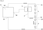
- Figure 3 shows a first state of this electronic assembly.
- the driver 4 commands the switch 5 to be closed.
- the by-pass branch 3 shortcuts the first entry node 11 with the second entry node 13, so the first group of LEDs 1 does not receive electric supply.
- the second group of LEDs 2 is the only group of LEDs which emit light in this zone of the luminous device.
- the three LEDs 2 of the second group of LEDs emit light with an intensity suitable for the position light functionality of the headlamp.
- the driver 4, which commands the position of the switch 5, also adapts the current in the LEDs branch so that the three LEDs of the second group emit light with an adequate luminous intensity for this function. The light emitted by these LEDs will be projected by the lightguide shown in Figure 1 .
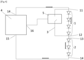
- Figure 4 shows a second state of this electronic assembly.
- the driver 4 commands the switch 5 to be open.
- the by-pass branch 3 is open, so the current goes through the first group of LEDs 1.
- both the first group 1 of LEDs and the second group 2 of LEDs emit light in this zone of the luminous device.
- the seven LEDs of both groups emit light with an intensity suitable for the DRL functionality of the headlamp.
- the driver 4, which commands the position of the switch 5, also adapts the current in the LEDs branch so that the seven LEDs of the both groups emit light with an adequate luminous intensity for this function. The light emitted by these LEDs will be projected by the same lightguide shown in Figure 1 .
- Figure 5 shows an alternative electronic arrangement of some elements of an automotive lighting device according to the invention.
- this arrangement could be installed in a rear lamp device, which provides the functionalities of brake light, rear position light and fog light.
- this device works in an analogue manner.
- the second and third group of LEDs need to be activated, so the first switch 5 of the first by-pass branch 3 is closed (so current does not run through the first group of LEDs) and the second switch 8 of the second by-pass branch 7 is open, so that current runs through the second group of LEDs 2. Since the third group of LEDs 6 does not have any associated by-pass branch, current runs through it whenever the LED section is fed with electric supply.
- the first and third group of LEDs 1, 6 need to be activated, so the second switch 8 of the second by-pass branch 7 is closed (so current does not run through the second group of LEDs 2) and the first switch 5 of the first by-pass branch 3 is open, so that current runs through the first group of LEDs 1. Since the third group of LEDs 6 do not have any associated by-pass branch, current runs through it whenever the LED section is fed with electric supply.
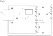
- Figure 6 shows a different feature of the invention, that may be combined with the embodiments of any of Figures 2 to 5 .
- This additional group of LEDs 18 can be configured to provide a lighting function which is different from the lighting functions performed by the first, second and third group of LEDs. However, this additional group of LEDs 18 may be installed in the same substrate as these first, second and third group of LEDs.
Landscapes
- Engineering & Computer Science (AREA)
- Mechanical Engineering (AREA)
- Lighting Device Outwards From Vehicle And Optical Signal (AREA)
Abstract
The present invention provides an automotive luminous device (10), comprising:
- a first group of light sources (1);
- a second group of light sources (2);
- a first by-pass branch (3) comprising a first switch (5), that is connected in parallel with the first group of light sources; and
- a driver (4).
- a first group of light sources (1);
- a second group of light sources (2);
- a first by-pass branch (3) comprising a first switch (5), that is connected in parallel with the first group of light sources; and
- a driver (4).
The driver (4) is configured to manage electric supply for the first group of light sources (1) and for the second group of light sources (2). The driver (4) is also configured to open and close the first switch (5) to activate the first group of light sources to provide a first lighting function in combination with the second group of light sources when the first switch (5) is open, and to activate the second group of light sources to provide a second lighting function when the first switch (5) is closed.
Finally, the device includes an optical element (9) to project receiving light outside the luminous device.
Description
- This invention belongs to the field of automotive luminous devices and the usage of light sources for different lighting and signalling functions.
- Automotive lighting market can be considered one of the most competitive ones and new functions are constantly required.
- These devices are in charge of many different lighting and signalling functions. To provide these functions, different light sources, such as Light Emitting Diodes (LEDs) are usually employed. These LEDs when fed by an appropriate current are able to provide the luminous flux required by these functions.
- Each function has a different requirement concerning colour and luminous intensity. Hence, different LEDs are usually used for each function. Further, each module has a different location within the device, and cooperates with a different optical element (reflectors, lenses, lightguides, etc). This need or incorporating different lighting modules leads to a bulkier light system, which is not compatible with the space constraint of certain car models.
- The present invention provides an alternative solution for this problem.
- The present invention provides a solution for these problems by means of an automotive luminous device, comprising:
- a first group of light sources, the first group comprising a first entry node and a first exit node;
- a second group of light sources, the second group comprising a second entry node and a second exit node, wherein the second group of light sources is arranged in series with the first group of light sources;
- a driver configured to receive a command from a control module and to manage electric supply for the first group of light sources and for the second group of light sources.
- According to the invention, the luminous device further comprises a first by-pass branch connecting the first entry node with the first exit node by the interposition of a first switch. Besides, the driver is configured to open and close the first switch in function of the command received from the control module, wherein the driver is configured to activate the first group of light sources to provide a first lighting function in combination with the second group of light sources when the first switch is open, and to activate the second group of light sources to provide a second lighting function when the first switch is closed. Finally, the luminous device also comprises an optical element being configured to receive the light from the first group of light sources and from the second group of light sources when the first switch is open, or from the second group of light sources when the first switch is closed and being configured to project the receiving light outside the luminous device.
- In other words, the first switch has two states, noting that it is the driver that controls the state of the switch:
- an open state during which current flows to the first group of light sources and to the second group of light sources, activating them to perform the first lighting function; and
- a closed state in which the current bypasses the first group of light sources and feeds the second group of light sources, so that the second group of light sources is switched on alone to perform the second lighting function, which is different from the first lighting function.
- With this device, two different lighting functions, projected by the same optical element, may be operated by a single driver. The driver remains unaltered in its operation, and there is no need to provide a printed circuit board for each functionality. The total amount of light sources is minimised while keeping the operation simple.
- Here, a command corresponds to a lighting instruction. A "lighting instruction" may include parameter(s) related to the lighting function that needs to be realized, such as the light flux (measurement unit: lumen) or the luminous intensity (measurement unit: candela). A control module can be an electronic control unit (ECU) as an engine management system implemented in the vehicle. The automotive lighting device is thus intended to interact with the control unit at the vehicle level.
- Each group of light sources comprises at least one light source. When there are more than one light source, these light sources within the corresponding light source group can be arranged in series or in parallel. The first group is arranged with respect to the second group in series, so that the first by-pass branch only creates a by-pass channel for the first group: when the first switch is closed, the current goes through the first by-pass instead of through the first group, so the first group does not receive power supply and the second group are the only light sources that provide light. When the switch is open, the current goes through the first and second group of light sources, providing a more intense light output. As seems evident, the role of first group and second group is exchangeable, since the first group and the second group are connected in series, so that the switch can control the current between the second entry node and the second exit node, instead of first ones. Further, the switch can be integrated in the driver, forming a driver group comprising the driver and the switch.
- The driver device is arranged to manage the electric supply of the light sources. The luminous device comprises a power source, which can be external to the luminous device. The driver may be located at different positions and with different electric connections to manage the electric supply that runs through the light sources.
- In some particular embodiments, the driver may include a current converter, for example DC/DC converter of the type of the type Buck, Boost, SEPIC, Flyback or also linear driver. Further, the driver may include a tunable power supply component.
- In some particular embodiments, the driver is also configured to provide a different voltage for the group of light sources depending on the instructions received from the control module.
- When two different lighting functions are to be provided, it is possible that each one requires a different nominal current value, so it is possible that the needed voltage is different.
- In some particular embodiments, the light sources are solid-state light sources. The term "solid state" refers to light emitted by solid-state electroluminescence, which uses semiconductors to convert electricity into light. Compared to incandescent lighting, solid state lighting creates visible light with reduced heat generation and less energy dissipation. The typically small mass of a solid-state electronic lighting device provides for greater resistance to shock and vibration compared to brittle glass tubes/bulbs and long, thin filament wires. They also eliminate filament evaporation, potentially increasing the lifespan of the illumination device. Some examples of these types of lighting comprise semiconductor light-emitting diodes (LEDs), organic light-emitting diodes (OLED), or polymer light-emitting diodes (PLED) as sources of illumination rather than electrical filaments, plasma or gas. These light sources are specifically advantageous, since they provide the required luminous properties for the automotive regulations with a high efficiency and reliability.
- In some particular embodiments, the automotive luminous device further comprises:
- a third group of light sources, the third group comprising a third entry node and a third exit node, wherein the third group of light sources is arranged in series with the first group of light sources and with the second group of light sources; and
- a second by-pass branch, connecting the first entry node or the second entry node with the third entry node by the interposition of a second switch;
- the driver is further configured to provide electric supply for the third group of light sources, the driver being also configured to open and close the second switch, and also configured to activate the third group of light sources to provide a third lighting function when the second switch is closed; and
- the optical element is further configured to receive the light from the third group of light sources and project it outside the luminous device.
- The concept of the invention may be extended to more than two different functions: a further switch is used to extend the possible operation scenarios.
- In some particular embodiments, the third lighting function is a fog light function or a turning indicator function.
- These functions may be provided by the same lighting module, to achieve a compact design.
- In some particular embodiments, the first switch and/or the second switch comprises a transistor, such as a Bipolar Junction Transistor or a Metal Oxide Semiconductor Field-Effect Transistor.
- Any of these elements can be chosen. Metal Oxide Semiconductor Field-Effect Transistors are usually preferred due to their easy polarisation requirements.
- In some particular embodiments, the first group of light sources and/or the second group of light sources comprises at least two light sources arranged in series.
- In some particular embodiments, the optical element comprises a light guide, a reflector, a diffusing screen or a combination of at least two of the above elements.
- An optical element is an element that has some optical properties to receive a light beam and emit it in a certain direction and/or shape, as a person skilled in automotive lighting would construe without any additional burden. Reflectors, collimators, light guides, projection lenses, etc., or the combination thereof are some examples of these optical elements which are useful for transforming the light beams emitted by the light source into an acceptable light pattern for the functionality chosen for the lighting device.
- In this specific case, light guides, alone or in combination with diffusing screens, would be especially suitable for the present invention, since the involved lighting functionalities are usually projected by light guides.
- In some particular embodiments, the light sources are installed in a substrate which may comprise printed circuits, the substrate being otherwise called printed circuit board (PCB). For example, the first group of light sources and the second group of light sources are arranged on a same support, preferably on a same printed circuit board.
- In some particular embodiments, the electronic substrate is a rigid electronic substrate. Alternatively, the substrate can be made flexible.
- A rigid substrate should be understood in the sense of what the skilled person would construe. A skilled person knows the difference between a rigid substrate and a flexible substrate. Although every material is "flexible" in the sense that it has a stress-strain curve, a substrate which does not deform by its own weight when held by one of its ends is deemed to be rigid, while a substrate which suffer a substantial deformation when held by one of its ends is considered to be flexible. In any case, board manufacturers offer a "flexible" model and a "rigid" model, while any skilled person knows the difference between them.
- In some particular embodiments, the first lighting function is a position light function and the second lighting function can be a function chosen among daytime running light function or brake light function.
- In a further inventive aspect, the invention provides an automotive headlamp or rear lamp comprising an automotive luminous device according to the first inventive aspect.
- Unless otherwise defined, all terms (including technical and scientific terms) used herein are to be interpreted as is customary in the art. It will be further understood that terms in common usage should also be interpreted as is customary in the relevant art and not in an idealised or overly formal sense unless expressly so defined herein.
- To complete the description and in order to provide for a better understanding of the invention, a set of drawings is provided. Said drawings form an integral part of the description and illustrate an embodiment of the invention, which should not be interpreted as restricting the scope of the invention, but just as an example of how the invention can be carried out. The drawings comprise the following figures:
- [
Fig 1 ] shows an automotive lighting device according to the invention, which is installed in a vehicle. - [
Fig 2 ] shows an electronic arrangement of some elements of the automotive lighting device ofFigure 1 . - [
Fig 3 ] and [Fig 4 ] show different states of the electronic assembly ofFigure 2 . - [
Fig 5 ] shows an alternative electronic arrangement of some elements of an automotive lighting device according to the invention. - [
Fig 6 ] shows a feature of the invention which can be combined with any of the previous embodiments. - In these figures, the following reference numbers have been used:
- 1
- First group of LEDs
- 2
- Second group of LEDs
- 3
- First by-pass branch
- 4
- Driver
- 5
- First witch
- 6
- Third group of LEDs
- 7
- Second by-pass branch
- 8
- Second switch
- 9
- Lightguide
- 10
- Automotive lighting module
- 11
- First entry node
- 12
- First exit node
- 13
- Second entry node
- 14
- Second exit node
- 15
- First terminal of the driver
- 16
- Second terminal of the driver
- 17
- Third terminal of the driver
- 18
- Additional group of LEDs
- 100
- Automotive headlamp
- The example embodiments are described in sufficient detail to enable those of ordinary skill in the art to embody and implement the systems and processes herein described. It is important to understand that embodiments can be provided in many alternate forms and should not be construed as limited to the examples set forth herein.
- Accordingly, while embodiment can be modified in various ways and take on various alternative forms, specific embodiments thereof are shown in the drawings and described in detail below as examples. There is no intent to limit the particular forms disclosed. On the contrary, all modifications, equivalents, and alternatives falling within the scope of the appended claims should be included. Elements of the example embodiments are consistently denoted by the same reference numerals throughout the drawings and detailed description where appropriate.
-
Figure 1 shows anautomotive lighting device 10 according to the invention, which is installed in avehicle 100. Specifically, thisautomotive lighting device 10 is a lighting module integrated in aheadlamp 100 , which is configured to provide the functionalities of Daytime Running Light (DRL) and Position Light at the same time, by means of thesame lightguide 9. -
Figure 2 shows an electronic arrangement of some elements of the automotive lighting device ofFigure 1 . - This electronic arrangement comprises a first group of
LEDs 1, a second group ofLEDs 2, a first by-pass branch 3 and adriver 4. - The first group of
LEDs 1 comprises four LEDs arranged in series. This first group of LEDs comprises afirst entry node 11 and afirst exit node 12. The second group ofLEDs 2 comprises three LEDs arranged in series. The second group of LEDs comprises asecond entry node 13 and asecond exit node 14. Thesecond entry node 13 is arranged at the same electric potential as thefirst exit node 12, since the first group ofLEDs 1 and the second group ofLEDs 2 are arranged in series. - There is also a first by-
pass branch 3 arranged between thefirst entry node 11 and thesecond entry node 13. This first by-pass branch 3 comprises aswitch 5, which in this case is a Metal Oxide Semiconductor Field-Effect Transistor (MOSFET). A Bipolar Junction Transistor (BJT) or any other semiconductor element which may work as a switch could also be used for this purpose. - The
driver 4 is arranged to manage the electric supply received by the first group ofLEDs 1 and by the second group ofLEDs 2. In thisFigure 2 , the driver receives the electric supply and has afirst terminal 15 connected to thefirst entry node 11 and asecond terminal 16 connected to thesecond exit node 14. A third terminal 17 ofdriver 4 is in charge of controlling theswitch 5. -
Figure 3 shows a first state of this electronic assembly. - In this figure, the
driver 4 commands theswitch 5 to be closed. Hence, the by-pass branch 3 shortcuts thefirst entry node 11 with thesecond entry node 13, so the first group ofLEDs 1 does not receive electric supply. In this case, the second group ofLEDs 2 is the only group of LEDs which emit light in this zone of the luminous device. The threeLEDs 2 of the second group of LEDs emit light with an intensity suitable for the position light functionality of the headlamp. Thedriver 4, which commands the position of theswitch 5, also adapts the current in the LEDs branch so that the three LEDs of the second group emit light with an adequate luminous intensity for this function. The light emitted by these LEDs will be projected by the lightguide shown inFigure 1 . -
Figure 4 shows a second state of this electronic assembly. - In this figure, the
driver 4 commands theswitch 5 to be open. Hence, the by-pass branch 3 is open, so the current goes through the first group ofLEDs 1. In this case, both thefirst group 1 of LEDs and thesecond group 2 of LEDs emit light in this zone of the luminous device. The seven LEDs of both groups emit light with an intensity suitable for the DRL functionality of the headlamp. Thedriver 4, which commands the position of theswitch 5, also adapts the current in the LEDs branch so that the seven LEDs of the both groups emit light with an adequate luminous intensity for this function. The light emitted by these LEDs will be projected by the same lightguide shown inFigure 1 . -
Figure 5 shows an alternative electronic arrangement of some elements of an automotive lighting device according to the invention. - In this case, this arrangement could be installed in a rear lamp device, which provides the functionalities of brake light, rear position light and fog light.
- In this case, apart from the
first group 1 of LEDs, thesecond group 2 of LEDs, the first by-pass branch 3 and the driver, there is athird group 6 of three LEDs and a second by-pass branch 7, which connects thesecond entry node 13 with thesecond exit node 14. - In a similar case as the one shown in
Figures 2 ,3 and4 , this device works in an analogue manner. - When brake light is required, the second and third group of LEDs need to be activated, so the
first switch 5 of the first by-pass branch 3 is closed (so current does not run through the first group of LEDs) and thesecond switch 8 of the second by-pass branch 7 is open, so that current runs through the second group ofLEDs 2. Since the third group ofLEDs 6 does not have any associated by-pass branch, current runs through it whenever the LED section is fed with electric supply. - When rear position light is required, only the third group of
LEDs 6 need to be activated, so theswitches pass branches - When fog light is required, the first and third group of
LEDs second switch 8 of the second by-pass branch 7 is closed (so current does not run through the second group of LEDs 2) and thefirst switch 5 of the first by-pass branch 3 is open, so that current runs through the first group ofLEDs 1. Since the third group ofLEDs 6 do not have any associated by-pass branch, current runs through it whenever the LED section is fed with electric supply. -
Figure 6 shows a different feature of the invention, that may be combined with the embodiments of any ofFigures 2 to 5 . - In this case, there is an additional group of
LEDs 18 which are also fed and controlled by thedriver 4. However, these additional group ofLEDs 18 does not take part in the controlled functions of the first, second and third group of LEDs. However, the presence and operation of this additional group ofLEDs 18 is compatible with any of the embodiments described above. - This additional group of
LEDs 18 can be configured to provide a lighting function which is different from the lighting functions performed by the first, second and third group of LEDs. However, this additional group ofLEDs 18 may be installed in the same substrate as these first, second and third group of LEDs.
Claims (9)
- Automotive luminous device (10), comprising:• a first group of light sources (1), the first group (1) comprising a first entry node (11) and a first exit node (12);• a second group of light sources (2), the second group (2) comprising a second entry node (13) and a second exit node (14), wherein the second group of light sources (2) is arranged in series with the first group of light sources (1);• a driver (4) configured to receive a command from a control module and to manage electric supply for the first group of light sources (1) and for the second group of light sources (2),characterized in that :• the luminous device (10) further comprises a first by-pass branch (3) connecting the first entry node (11) with the first exit node (12) by the interposition of a first switch (5);• the driver (4) is configured to open and close the first switch (5) in function of the command received from the control module, wherein the driver is configured to activate the first group of light sources to provide a first lighting function in combination with the second group of light sources when the first switch (5) is open, and to activate the second group of light sources to provide a second lighting function when the first switch (5) is closed; and• the luminous device (10) further comprises an optical element (9) being configured to receive the light from the first group of light sources (1) and from the second group (2) of light sources when the first switch (5) is open, or from the second group (2) of light sources when the first switch (5) is closed and being configured to project the receiving light outside the luminous device.
- Automotive luminous device (10) according to claim 1, wherein the driver (4) is also configured to provide a different voltage for the groups of light sources (1, 2) depending on the command received from the control module.
- Automotive luminous device (10) according to claim 1 or claim 2, further comprising:• a third group of light sources (6), the third group of light sources (6) comprising a third entry node and a third exit node, wherein the third group of light sources (6) is arranged in series with the first group of light sources (1) and with the second group of light sources (2); and• a second by-pass branch (7), connecting the first entry node or the second entry node with the third entry node by the interposition of a second switch (8);wherein• the driver (4) is further configured to provide electric supply for the third group of light sources (6), the driver (4) being also configured to open and close the second switch (8), and also configured to activate the third group of light sources (6) to provide a third lighting function when the second switch (8) is closed; and• the optical element (9) is further configured to receive the light from the third group of light sources (6) and project it outside the luminous device (10).
- Automotive luminous device (10) according to claim 3, wherein the third lighting function is a fog light function or a turning indicator function.
- Automotive luminous device (10) according to any of the preceding claims, wherein the first switch and/or the second switch comprises a transistor, such as a Bipolar Junction Transistor or a Metal Oxide Semiconductor Field-Effect Transistor.
- Automotive luminous device (10) according to any of the preceding claims, wherein the first group of light sources and/or the second group of light sources comprises at least two light sources arranged in series.
- Automotive luminous device (10) according to any of the preceding claims, wherein the optical element comprises a light guide or a reflector.
- Automotive luminous device (10) according to any of the preceding claims, wherein the first lighting function is a position light function and the second lighting function can be a function chosen between daytime running light function and brake light function.
- Automotive headlamp (100) or rear lamp comprising an automotive luminous device (10) according to any of the preceding claims.
Priority Applications (1)
| Application Number | Priority Date | Filing Date | Title |
|---|---|---|---|
| EP23218653.6A EP4574569A1 (en) | 2023-12-20 | 2023-12-20 | Automotive luminous device |
Applications Claiming Priority (1)
| Application Number | Priority Date | Filing Date | Title |
|---|---|---|---|
| EP23218653.6A EP4574569A1 (en) | 2023-12-20 | 2023-12-20 | Automotive luminous device |
Publications (1)
| Publication Number | Publication Date |
|---|---|
| EP4574569A1 true EP4574569A1 (en) | 2025-06-25 |
Family
ID=89224307
Family Applications (1)
| Application Number | Title | Priority Date | Filing Date |
|---|---|---|---|
| EP23218653.6A Pending EP4574569A1 (en) | 2023-12-20 | 2023-12-20 | Automotive luminous device |
Country Status (1)
| Country | Link |
|---|---|
| EP (1) | EP4574569A1 (en) |
Citations (9)
| Publication number | Priority date | Publication date | Assignee | Title |
|---|---|---|---|---|
| JP4007096B2 (en) * | 2002-06-28 | 2007-11-14 | 松下電工株式会社 | Lighting device |
| US20090230893A1 (en) * | 2005-10-14 | 2009-09-17 | Patent-Treuhand-Gesellschaft Fur Elektrische Gluhlampen Mbh | Multifunctional Motor Vehicle Headlight Module, in Particular for the Front Region of a Motor Vehicle |
| US20110080753A1 (en) * | 2008-05-28 | 2011-04-07 | Osram Gesellschaft Mit Beschraenkter Haftung | Vehicle lighting device with at least two semiconductor lamp elements |
| EP2381741A2 (en) * | 2010-04-23 | 2011-10-26 | Panasonic Electric Works Co., Ltd. | Lighting device, headclamp apparatus and vehicle using same |
| US20150069906A1 (en) * | 2012-02-01 | 2015-03-12 | Osram Gmbh | Circuit arrangement, lighting unit for a vehicle and method for driving semiconductor lighting elements |
| US20170006670A1 (en) * | 2015-05-26 | 2017-01-05 | Valeo Vision | Light module for a light device of a motor vehicle and associated method |
| EP3235683A1 (en) * | 2016-04-22 | 2017-10-25 | Rohm Co., Ltd. | Light-emitting element driving semiconductor integrated circuit, light-emitting element driving device, light-emitting device, and vehicle |
| WO2022133671A1 (en) * | 2020-12-21 | 2022-06-30 | Foshan Ichikoh Valeo Auto Lighting Systems Co., Ltd. | Light assembly for performing lighting functions with switching units in low side position |
| JP2022152828A (en) * | 2021-03-29 | 2022-10-12 | 株式会社小糸製作所 | Vehicular lighting fixture |
-
2023
- 2023-12-20 EP EP23218653.6A patent/EP4574569A1/en active Pending
Patent Citations (9)
| Publication number | Priority date | Publication date | Assignee | Title |
|---|---|---|---|---|
| JP4007096B2 (en) * | 2002-06-28 | 2007-11-14 | 松下電工株式会社 | Lighting device |
| US20090230893A1 (en) * | 2005-10-14 | 2009-09-17 | Patent-Treuhand-Gesellschaft Fur Elektrische Gluhlampen Mbh | Multifunctional Motor Vehicle Headlight Module, in Particular for the Front Region of a Motor Vehicle |
| US20110080753A1 (en) * | 2008-05-28 | 2011-04-07 | Osram Gesellschaft Mit Beschraenkter Haftung | Vehicle lighting device with at least two semiconductor lamp elements |
| EP2381741A2 (en) * | 2010-04-23 | 2011-10-26 | Panasonic Electric Works Co., Ltd. | Lighting device, headclamp apparatus and vehicle using same |
| US20150069906A1 (en) * | 2012-02-01 | 2015-03-12 | Osram Gmbh | Circuit arrangement, lighting unit for a vehicle and method for driving semiconductor lighting elements |
| US20170006670A1 (en) * | 2015-05-26 | 2017-01-05 | Valeo Vision | Light module for a light device of a motor vehicle and associated method |
| EP3235683A1 (en) * | 2016-04-22 | 2017-10-25 | Rohm Co., Ltd. | Light-emitting element driving semiconductor integrated circuit, light-emitting element driving device, light-emitting device, and vehicle |
| WO2022133671A1 (en) * | 2020-12-21 | 2022-06-30 | Foshan Ichikoh Valeo Auto Lighting Systems Co., Ltd. | Light assembly for performing lighting functions with switching units in low side position |
| JP2022152828A (en) * | 2021-03-29 | 2022-10-12 | 株式会社小糸製作所 | Vehicular lighting fixture |
Similar Documents
| Publication | Publication Date | Title |
|---|---|---|
| CN109548227B (en) | Lighting circuit and vehicle lamp | |
| US20030147252A1 (en) | Front lighting system for a motor vehicle | |
| JP6101587B2 (en) | Vehicle headlamp | |
| US7854538B2 (en) | High intensity tactical vehicle infrared and white headlight system | |
| KR20110013503A (en) | Vehicle lighting device having at least two semiconductor light emitting devices | |
| CN111372355A (en) | Lamp module | |
| JPWO2018186187A1 (en) | Vehicle lighting | |
| JP2014116354A (en) | Light-emitting element drive unit, luminaire | |
| WO2021165133A1 (en) | Method for projecting light in the interior of a vehicle, automotive light projector and automotive light assembly | |
| EP3716733B1 (en) | Electronic assembly and automotive lighting device | |
| WO2025132884A1 (en) | A lighting circuit for an automotive luminous device and an automotive luminous device | |
| EP4253830A1 (en) | Automotive luminous device | |
| EP4110020B1 (en) | Electronic assembly and automotive lighting device | |
| EP4203198A1 (en) | Automotive luminous device | |
| US11178736B2 (en) | Electronic assembly, lighting device and method for manufacturing a lighting device | |
| EP3562273A1 (en) | Electronic assembly and lighting device | |
| WO2022122618A2 (en) | Automotive lighting device | |
| EP4253832A1 (en) | Automotive luminous arrangement | |
| EP3581847A1 (en) | Automotive lighting device | |
| CN112789948A (en) | Lighting device for motor vehicle | |
| EP4397902A1 (en) | Luminous module and automotive luminous device | |
| US20250048522A1 (en) | Electronic assembly and automotive luminous device | |
| US20240224393A1 (en) | Electronic assembly for an automotive lighting device, automotive lighting device and method for controlling light sources in an automotive lighting device | |
| US20180070418A1 (en) | Voltage-dependent operation of individual light sources | |
| EP4203620A1 (en) | Electronic assembly for an automotive luminous device and automotive luminous device |
Legal Events
| Date | Code | Title | Description |
|---|---|---|---|
| PUAI | Public reference made under article 153(3) epc to a published international application that has entered the european phase |
Free format text: ORIGINAL CODE: 0009012 |
|
| STAA | Information on the status of an ep patent application or granted ep patent |
Free format text: STATUS: THE APPLICATION HAS BEEN PUBLISHED |
|
| AK | Designated contracting states |
Kind code of ref document: A1 Designated state(s): AL AT BE BG CH CY CZ DE DK EE ES FI FR GB GR HR HU IE IS IT LI LT LU LV MC ME MK MT NL NO PL PT RO RS SE SI SK SM TR |
|
| STAA | Information on the status of an ep patent application or granted ep patent |
Free format text: STATUS: THE APPLICATION IS DEEMED TO BE WITHDRAWN |