EP4574567A1 - Method and system for condition monitoring of mining vehicle - Google Patents
Method and system for condition monitoring of mining vehicle Download PDFInfo
- Publication number
- EP4574567A1 EP4574567A1 EP23217708.9A EP23217708A EP4574567A1 EP 4574567 A1 EP4574567 A1 EP 4574567A1 EP 23217708 A EP23217708 A EP 23217708A EP 4574567 A1 EP4574567 A1 EP 4574567A1
- Authority
- EP
- European Patent Office
- Prior art keywords
- dump box
- mining vehicle
- loading
- lifting cylinder
- hydraulic circuit
- Prior art date
- Legal status (The legal status is an assumption and is not a legal conclusion. Google has not performed a legal analysis and makes no representation as to the accuracy of the status listed.)
- Pending
Links
Images


Classifications
-
- B—PERFORMING OPERATIONS; TRANSPORTING
- B60—VEHICLES IN GENERAL
- B60P—VEHICLES ADAPTED FOR LOAD TRANSPORTATION OR TO TRANSPORT, TO CARRY, OR TO COMPRISE SPECIAL LOADS OR OBJECTS
- B60P1/00—Vehicles predominantly for transporting loads and modified to facilitate loading, consolidating the load, or unloading
- B60P1/04—Vehicles predominantly for transporting loads and modified to facilitate loading, consolidating the load, or unloading with a tipping movement of load-transporting element
- B60P1/16—Vehicles predominantly for transporting loads and modified to facilitate loading, consolidating the load, or unloading with a tipping movement of load-transporting element actuated by fluid-operated mechanisms
- B60P1/162—Vehicles predominantly for transporting loads and modified to facilitate loading, consolidating the load, or unloading with a tipping movement of load-transporting element actuated by fluid-operated mechanisms the hydraulic system itself
-
- F—MECHANICAL ENGINEERING; LIGHTING; HEATING; WEAPONS; BLASTING
- F15—FLUID-PRESSURE ACTUATORS; HYDRAULICS OR PNEUMATICS IN GENERAL
- F15B—SYSTEMS ACTING BY MEANS OF FLUIDS IN GENERAL; FLUID-PRESSURE ACTUATORS, e.g. SERVOMOTORS; DETAILS OF FLUID-PRESSURE SYSTEMS, NOT OTHERWISE PROVIDED FOR
- F15B19/00—Testing; Calibrating; Fault detection or monitoring; Simulation or modelling of fluid-pressure systems or apparatus not otherwise provided for
- F15B19/005—Fault detection or monitoring
Definitions
- the invention relates to a method and system for condition monitoring of a mining vehicle.
- Mining vehicles provided with a dump box are generally used for transporting heavy loads, such as rock or soil.
- the mining vehicles of this kind comprise generally a body, a dump box to be supported to the body, at least one dump box lifting cylinder for operating the dump box and an operating circuit comprising a hydraulic circuit for operating the at least one lifting cylinder.
- Pressurized dump box lifting cylinders either raise the dump box upwards or lower the dump box downwards towards the body.
- the pressured lifting cylinder causes needless stress to the body of the mining vehicle if the hydraulic circuit needlessly has pressure on. Therefore, at least extremely heavy mining vehicles, such as dump trucks or other trucks used in mining and excavation sites typically comprise also pressure release valves for depressurizing the at least one lifting cylinder, i.e., for releasing the pressure from the at least one lifting cylinder, thereby relieving tension caused by the pressurized lifting cylinder to the vehicle body.
- the present application relates generally to providing a new method and a new system for condition monitoring of a mining vehicle.
- the method relates to a condition monitoring of a mining vehicle, which mining vehicle comprises a body, a dump box, at least one dump box lifting cylinder for operating the dump box, a hydraulic circuit for operating the lifting cylinder, and a pressure release valve for the hydraulic circuit for depressurizing the lifting cylinder.
- the method comprises controlling a hydraulic circuit to pressurize the lifting cylinder for changing a position of the dump box relative to the body, controlling a respective pressure release valve to open the hydraulic circuit for depressurizing the lifting cylinder, measuring a loading applied by the dump box to the body of the mining vehicle both in response to changing the position of the dump box relative to the body of the mining vehicle and in response to control the pressure release valve to open the hydraulic circuit for depressurizing the lifting cylinder, and determining, based on the said loading measurements, a state of the pressure release valve in response to control the pressure release valve to open the hydraulic circuit for depressurizing the lifting cylinder.
- the system comprises at least one loading measurement element for measuring a loading applied by the dump box to the body of the mining vehicle, and a control unit configured to receive loading measurements from the at least one loading measurement element and to control the operation of the lifting cylinder for operating the dump box, wherein the control unit is configured to control a hydraulic circuit to pressurize the lifting cylinder for changing a position of the dump box relative to the body, to control a respective pressure release valve to open the hydraulic circuit for depressurizing the lifting cylinder, to receive loading measurements of a loading applied by the dump box to the body of the mining vehicle both in response to changing the position of the dump box relative to the body of the mining vehicle and in response to control the pressure release valve to open the hydraulic circuit for depressurizing the lifting cylinder, and to determine, based on the said loading measurements, a state of the pressure release valve in response to control the pressure release valve to open the hydraulic circuit for depressurizing the lifting cylinder.
- the present application is based on the idea of monitoring a correct functioning of the at least one pressure release valve to release the pressure in the at least one lifting cylinder of the dump box.
- the at least one lifting cylinder is pressurized for moving the dump box away from the body of the mining vehicle and/or against the body of the mining vehicle and the at least one lifting cylinder is depressurized for allowing the dump box to rest freely against the body of the mining vehicle.
- the loadings applied by the dump box to the body of the mining vehicle are measured in response to the said operations.
- One of the advantages of the present application is that it provides a simple and easily implementable solution for monitoring the condition of the mining vehicle as far it considers a correct functioning of the at least one pressure release valve for releasing the pressure in the at least one lifting cylinder of the dump box. Thereby a possible malfunction of the pressure release valve may be detected easily.
- the disclosed testing procedure may be carried out during a normal operation of the mining vehicle without any maintenance personnel and equipment external to the mining vehicle.
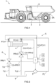
- FIG. 1 is a schematic side view of a mining vehicle 1, wherein the solution described herein may be utilized.
- the mining vehicle 1 comprises a body 2, which may also be called a frame 2, and a dump box 3, i.e., a tipping platform, supported to the body 2.
- the mining vehicle 1 further comprises at least one dump box lifting cylinder 4 for operating the dump box 3, i.e., for raising the dump box 3 upwards for tilting the dump box 3 about a swivelling axis SA for unloading a load carried by the dump box 3, and for lowering the dump box 3 back downwards for resting against the body 2.
- the mining vehicle 1 of Figure 1 comprises two lifting cylinders 4, i.e., one lifting cylinder 4 on the visible side of the mining vehicle 1, and one lifting cylinder 4 on the opposite invisible side of the mining vehicle 1.
- the mining vehicle 1 may comprise any applicable number of the lifting cylinders 4. Therefore, the mining vehicle may for example comprise only one lifting cylinder 4 that can be accommodated for example below the dump box 3 at a central part thereof.
- the mining vehicle 1 of Figure 1 is a dump truck that can be used in a mine, a quarry, or an excavation site, for instance, for transporting extremely heavy loads, such as blasted rock, rock material or soil from a loading site to an unloading site.
- extremely heavy loads such as blasted rock, rock material or soil from a loading site to an unloading site.
- the solution described herein may be used in other mining vehicles or other transport vehicles comprising a dump box or a loading platform being a form of a tipping platform.
- the mining vehicle 1 further comprises an arrangement 5 for operating the at least one lifting cylinder 4.
- the arrangement 5 comprises a hydraulic circuit 6 and a control unit 7 intended to control operations of components in the hydraulic circuit 6.
- An example embodiment of the arrangement 5 with a single lifting cylinder 4 is shown schematically in Figure 2 . If there are two or more lifting cylinders 4 in a mining vehicle, other example embodiments of an arrangement 5 for operating the two or more lifting cylinders 4 may be implemented by duplicating necessary components in the hydraulic circuit.
- the control unit 7 may be a control unit configured to control only the operation of the hydraulic circuit 6 for operating the dump box 3. Alternatively, the control unit 7 may be a control unit configured to operate also other operations in the mining vehicle 1.
- the control unit 7 can for example be a computer or some other device or means comprising a microprocessor or a microcontroller which is configured to execute a software program for carrying out pre-designed operations for operating the hydraulic circuit 6 for implementing a method and a system for monitoring a condition of the mining vehicle 1 as disclosed herein.
- the hydraulic circuit 6 of Figure 2 comprises a tank T for forming a reservoir for preserving a hydraulic pressure fluid used to operate the lifting cylinder 4.
- the hydraulic circuit 6 further comprises a pressure line PL comprising a pump P for supplying pressurized pressure fluid flow to the lifting cylinder 4, i.e., for pressurizing the lifting cylinder 4.
- the operation of the pump P is controlled by the control unit 7 through the respective control connection CO-P.
- the pressurized pressure fluid flow to the lifting cylinder 4 is directed either to a piston side of the lifting cylinder 4 through a respective first flow control valve FCV1 or to a piston rod side of the lifting cylinder 4 through a respective second flow control valve FCV2, as controlled by the control unit 7 through respective control connections CO-FCV1 and CO-FCV2.
- the piston side of the lifting cylinder 4 may be pressurized for moving the dump box 3 upwards, whereby the piston rod side of the lifting cylinder 4 will be pressurized for moving the dump box 3 downwards. That selection could, however, also be opposite.
- the hydraulic circuit 6 further comprises, for the lifting cylinder 4, a first tank line TL1 connected to the piston side of the lifting cylinder 4.
- the first tank line TL1 is provided with a first pressure release valve PRV1 for depressurizing the piston side of the lifting cylinder 4, i.e., for releasing the pressure in the piston side of the lifting cylinder 4 when controlled accordingly by the control unit 7 through the respective control connection CO-PRV1.
- the pressure line PL with the pump P therein, together with the first tank line TL1 comprising the first pressure release valve PRV1 are arranged to operate the piston side of the lifting cylinder 4.
- the hydraulic circuit 6 comprises, for the lifting cylinder 4, a second tank line TL2 connected to the piston rod side of the lifting cylinder 4.
- the second tank line TL2 is provided with a second pressure release valve PRV2 for depressurizing the piston rod side of the lifting cylinder 4, i.e., for releasing the pressure in the piston rod side of the lifting cylinder 4 when controlled accordingly by the control unit 7 through the respective control connection CO-PRV2.
- the pressure line PL with the pump P therein, together with the second tank line TL2 comprising the second pressure release valve PRV2 are arranged to operate the piston rod side of the lifting cylinder 4.
- the hydraulic circuit 6 may also comprise a throttle valve in one or both tank lines to throttle the flow of the pressure fluid to the tank T.
- a throttle TH is shown in Figure 2 in the first tank line TL1.
- the method comprises controlling a hydraulic circuit to pressurize the lifting cylinder for changing a position of the dump box relative to the body, controlling a respective pressure release valve to open the hydraulic circuit for depressurizing the lifting cylinder, measuring a loading applied by the dump box to the body of the mining vehicle both in response to changing the position of the dump box relative to the body of the mining vehicle and in response to control the pressure release valve to open the hydraulic circuit for depressurizing the lifting cylinder, and determining, based on the said loading measurements, a state of the pressure release valve in response to control the pressure release valve to open the hydraulic circuit for depressurizing the lifting cylinder.
- the system comprises at least one loading measurement element for measuring a loading applied by the dump box to the body of the mining vehicle, and a control unit configured to receive loading measurements from the at least one loading measurement element and to control the operation of the lifting cylinder for operating the dump box, wherein the control unit is configured to control a hydraulic circuit to pressurize the lifting cylinder for changing a position of the dump box relative to the body, to control a respective pressure release valve to open the hydraulic circuit for depressurizing the lifting cylinder, to receive loading measurements of a loading applied by the dump box to the body of the mining vehicle both in response to changing the position of the dump box relative to the body of the mining vehicle and in response to control the pressure release valve to open the hydraulic circuit for depressurizing the lifting cylinder,
- the present application is based on the idea of monitoring a correct functioning of the at least one pressure release valve to release the pressure in the at least one lifting cylinder of the dump box.
- the at least one lifting cylinder is pressurized for moving the dump box away from the body of the mining vehicle and/or against the body of the mining vehicle and the at least one lifting cylinder is depressurized for allowing the dump box to rest freely against the body of the mining vehicle.
- the loadings applied by the dump box to the body of the mining vehicle are measured in response to the said operations.
- the disclosed method and system for condition monitoring of the mining vehicle is intended to test a functioning of at least one of the first and the second pressure release valves PRV1, PRV2.
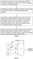
- Figure 3 discloses schematically a method for testing the functioning of at least one pressure release valve PRV1, PRV2.
- the respective system for testing a functioning of the at least one pressure release valve PRV1, PRV2 is also shown in Figure 2 , wherein Figure 2 further discloses a loading measurement element 8 for measuring a loading applied by the dump box 3 to the body 2 of the mining vehicle 1.
- the minimum number of the loading measurement elements 8 required is one. In some example embodiments the number of the loading measurement elements 8 may also be higher than one, whereby the loading applied by the dump box 3 to the body 2 of the mining vehicle 1 is some combination of the individual measurements of the two or more loading measurement elements 8 applied.
- the loading measurement element(s) 8 is(are) placed in the mining vehicle 1 at a position, wherein the dump box 3 subjects, either directly or indirectly, a loading to the loading measurement element 8 when the dump box 3 is down against the body 2 of the mining vehicle 1.
- the loading measurement element 8 may for example comprise a strain gauge or other device for measuring the loading applied by the dump box 3 to the body 2 of the mining vehicle 1.
- the example embodiment of Figure 2 as well as the example embodiments of Figures 4 and 7 also disclose a position measurement element 9 for indicating a position of the dump box 3 relative to the body 2 of the mining vehicle 1, and an arrangement 10 for determining a weight W of load in the dump box 3 of the mining vehicle 1.
- the position measurement element 9 and the arrangement 10 for determining the weight W of load are not part of a basic solution for the condition monitoring disclosed herein, but they may be applied in some example embodiments.
- the method of Figure 3 comprises controlling a hydraulic circuit to pressurize the lifting cylinder 4 for changing a position of the dump box 3 relative to the body 2 of the mining vehicle 2.
- a respective pressure release valve PRV1, PRV2 is controlled to open the hydraulic circuit 6 for depressurizing the lifting cylinder 4.
- a loading applied by the dump box 3 to the body 2 of the mining vehicle 1 is measured both in response to changing the position of the dump box 3 relative to the body 2 of the mining vehicle 1 and in response to control the pressure release valve PRV1, PRV2 to open the hydraulic circuit 6 for depressurizing the lifting cylinder 4.
- a state of the pressure release valve PRV1, PRV2 is determined in response to control the pressure release valve PRV1, PRV2 to open the hydraulic circuit 6 for depressurizing the lifting cylinder 4.
- either the piston side of the lifting cylinder 4 or the piston rod side of the lifting cylinder 4 is pressurized by a respective hydraulic circuit of the lifting cylinder 3.
- the dump box 3 is either raised upwards away from the body 2 of the mining vehicle 1 or especially pulled, i.e., forced, downwards against the body 2 of the mining vehicle 1.
- the dump box 3 rests freely against the body 2 of the mining vehicle 1.
- the loading applied by the dump box 3 to the body 2 of the mining vehicle 1, as indicated by the loading measurement element 8, decreases. If the dump box 3 is especially pulled downwards against the body 2 of the mining vehicle 1, the loading applied by the dump box 3 to the body 2 of the mining vehicle 1, as indicated by the loading measurement element 8, increases.
- the control of the respective pressure release valve that being either the first pressure release valve PRV1 or the second pressure release valve PRV2, to open the hydraulic circuit 6 for depressurizing the lifting cylinder 4 causes the dump box 3 to move downwards towards the body 2 of the mining vehicle 1. If the respective pressure release valve operates correctly, the dump box 3 will move in a certain time downwards against the body 2 of the mining vehicle 1 for resting freely against the body 2 of the mining vehicle 1.In this case, a respective loading measurement measured by the loading measurement element 8 should substantially correspond to the loading applied by the dump 3 to the body 2 of the mining vehicle 1 before starting the disclosed testing procedure. This indicates that the respective pressure release valve operates correctly.
- the dump box 3 will not move in a certain time downwards against the body 2 of the mining vehicle 1 for resting freely against the body 2 of the mining vehicle 1. In that case, a respective loading measurement measured by the loading measurement element 8 will not substantially correspond to the loading applied by the dump 3 to the body 2 of the mining vehicle 1 before starting the disclosed testing procedure. That indicates a malfunction of the respective pressure release valve.
- the disclosed testing procedure is controlled by the control unit 7.
- the loading measurements are also received and analysed by the control unit 7 for determining the state S-PRV1, S-PRV2 of the respective pressure release valve PRV1, PRV2.
- the state S-PRV1, S-PRV2 of the respective pressure release valve PRV1, PRV2 is determined after controlling the respective pressure release valve PRV1, PRV2 to open the hydraulic circuit 6 for depressurizing the lifting cylinder 4.
- the state S-PRV1, S-PRV2 of the pressure release valve PRV1, PRV2 may thus be considered to indicate a degree of opening of the pressure release valve PRV1, PRV2 in response to control the respective pressure release valve PRV1, PRV2 to open the hydraulic circuit 6 for depressurizing the lifting cylinder 4.
- the degree of the opening of the pressure release valve PRV1, PRV2 does not allow the dump box 3 to move in a certain time against the body 2 of the mining vehicle such that the dump box 3 rests freely against the body 2 of the mining vehicle 1. That can be identified by the respective loading measurements provided by the loading measurement element 8.
- Figure 4 shows a first loading measurement LM1 representing a loading applied by the dump box 3 to the body 2 of the mining vehicle 1 in response to changing the position of the dump box 3 relative to the body 2 of the mining vehicle, and a second loading measurement LM2 representing a loading applied by the dump box 3 to the body 2 of the mining vehicle 1 in response to control the pressure release valve to open the hydraulic circuit 6 for depressurizing the lifting cylinder 4.
- LM1 representing a loading applied by the dump box 3 to the body 2 of the mining vehicle 1 in response to changing the position of the dump box 3 relative to the body 2 of the mining vehicle
- a second loading measurement LM2 representing a loading applied by the dump box 3 to the body 2 of the mining vehicle 1 in response to control the pressure release valve to open the hydraulic circuit 6 for depressurizing the lifting cylinder 4.
- the difference LM2 - LM1 between the loading measurements LM1, LM2 is compared to the respective limit value ⁇ LM 12LIMIT for determining whether the respective pressure release valve has operated correctly for releasing the pressure on the respective side of the lifting cylinder 4. If the pressure release valve operates correctly, no pressure prevails in the lifting cylinder 4 so that no extra loading is applied by the dump box 3 to the body 2 of the mining vehicle 1 at a time when the dump box 3 should rest freely against the body 2 of the mining vehicle 1.
- the respective loading measurements are received and analysed by the control unit 7 for determining the state of the respective pressure release valve.
- the testing procedure is carried out only for one of the pressure release valves in the arrangement 5 for operating the lifting cylinder 4.
- the method comprises controlling, in interchangeable order, the hydraulic circuit to pressurize the lifting cylinder to change the position of the dump box upwards away from the body of the mining vehicle and downwards against the body of the mining vehicle.
- the method further comprises controlling the pressure release valve to open the hydraulic circuit for depressurizing the lifting cylinder in response to control the lifting cylinder to change the position of the dump box relative to the body.
- FIG. 5 , 6a and 6b show schematically a method for monitoring a condition of pressure release valves in a mining vehicle.
- Figure 7 shows schematically and partially a system for carrying out the method of Figures 5 , 6a and 6b .
- the dump box 3 is called a box.
- a loading applied by the dump box 3 to the body 2 of the mining vehicle 1 is measured and denoted with the reference sign S.
- This loading S is intended to indicate the loading which is applied by the dump box 3 to the body 2 of the mining vehicle 1 when the dump box 3 should rest freely against the body 2 of the mining vehicle 1.
- a level of loading corresponding to the loading S is shown schematically in Figures 6a and 6b with an upper horizontal broken line denoted with the reference sing "S".
- a loading measured by the loading measurement element 8 is shown in Figures 6a and 6b schematically with a continuous line indicated with the reference sign LM.
- Figure 6a discloses a theoretical loading curve to be provided by the loading measurement element 8 in response to the dump box 3 applying loading to the body 2 of the mining vehicle 1.
- Figure 6b discloses a loading measurement that was provided by a loading measurement element during a practical experiment in response to the dump box 3 having applied loading to the body 2 of the mining vehicle 1.
- the stage 100 corresponds to the period between the time instants T0 and T1.
- the control unit 7 controls the hydraulic circuit 6 of the lifting cylinder 4 to pressurize the lifting cylinder 4 on the piston side thereof for raising the dump box 3 upwards away from the body 2 of the mining vehicle 1.
- the stage 110 begins at time instant T1 and it is exemplified in Figure 6a also with the arrow R.
- the control unit 7 may receive one or more loading measurements from the loading measurement element 8 after time instant T1 between time instants T1 and T2 shown in Figures 6a and 6b and compare these one or more loading measurements to the loading S measured before starting to raise the dump box 3 upwards away from the body 2 of the mining vehicle 1. If the one or more loading measurements received between time instants T1 and T2 are smaller than the loading S measured before the time instant T1, the dump box 3 has started to raise upwards away from the body 2 of the mining vehicle 1.
- the control unit 7 may receive one or more position measurements, indicating the position of the dump box 3 relative to the body 2 of the mining vehicle 1, from a position measurement element 9 between time instants T1 and T2. The control unit 7 may then compare these one or more position measurements to a respective limit value for verifying that the dump box 3 has started to raise upwards away from the body 2 of the mining vehicle 1. The measurement of the position of the dump box 3 and the position measurement element 9 are discussed in more detail below.
- the method returns to the stage 110 discussed above. If it is verified that the dump box 3 is raising, the testing procedure is continued further.
- stage 130 the raising of the dump box 3 is stopped by respective control action(s) subjected to the hydraulic circuit 6 by the control unit 7.
- the stage 130 corresponds to time instant T2.
- the first loading measurement LM1 represents the loading applied by the dump box 3 to the body 2 of the mining vehicle 1 after the dump box 3 has been raised upwards away from the body 2 of the mining vehicle 1.
- the waiting period is called a stabilization time ST, during which a possible swaying of the dump box 3 is waited to stop. Referring to Figures 6a and 6b , this stabilization time ST starts at time instant T2.
- the first loading measurement LM1 is received by the control unit 7 in response to the dump box 3 having been raised upwards away from the body 2 of the mining vehicle 1.
- the first loading measurement LM1 represents the loading applied by the dump box 3 to the body 2 of the mining vehicle 1 after the dump box 3 has been raised upwards away from the body 2 of the mining vehicle 1.
- the first loading measurement LM1 is measured at the period between the time instants T2 and T3 after the stabilization time ST of the stage 140 as discussed above has passed.
- the first loading measurement LM1 should be substantially zero because the dump box 3 is tilted upwards, i.e., the dump box 3 does not rest freely on the body 2 of the mining vehicle 1 and does not therefore apply any loading to the loading measurement element 8.
- This level of loading corresponding to zero loading, or no loading is shown schematically in Figures 6a and 6b with a lower horizontal broken line denoted with the reference marking "Loading 0 kg".
- a minor measurement error may be present because of a possible minor inaccuracy in the operation of the loading measurement element 8.
- the first pressure release valve PRV1 is activated, i.e., controlled by the control unit 7, to open the hydraulic circuit 6 for depressurizing the lifting cylinder 4 on the piston side thereof. Because of that the pressure fluid remaining in the piston side of the lifting cylinder 4 should flow through the first pressure release valve PRV1 and through the first tank line TL1 into the tank T, allowing the dump box 3 to lower downwards back towards the body 2 of the mining vehicle 1.
- the first pressure release valve PRV1 is controlled to open the hydraulic circuit 6 at time instant T3.
- stage 170 the dump box 3 should move downwards for resting freely against the body 2 of the mining vehicle 1.
- this stage is called a test delay and referring to Figures 6a and 6b , the stage 170 refers to the period between the time instants T3 and T4.
- the second loading measurement LM2 is received by the control unit 7 in response to control the first pressure release valve PRV1 to open the hydraulic circuit 6 for depressurizing the lifting cylinder 4.
- the second loading measurement LM2 represents the loading applied by the dump box 3 to the body 2 of the mining vehicle 1 after the dump box 3 should have returned downwards with an intention to again rest freely against the body 2 of the mining vehicle 1.
- the second loading measurement LM2 is measured at the period between the time instants T4 and T5. No specific stabilization time should not be needed herein because supposedly the dump box 3 rests firmly against the body 2 of the mining vehicle 1. Therefore, at this stage the second loading measurement LM2 should be substantially the same as the loading S measured at the beginning of the testing procedure. However, a minor measurement error may be present because of a possible minor inaccuracy in the operation of the loading measurement element 8.
- a first loading difference ⁇ LM 12 LM2 - LM1 representing the difference between the first LM1 and second LM2 loading measurements is determined.
- the first loading difference ⁇ LM 12 is then compared to a first limit value ⁇ LM 12LIMIT set for determining the state of the first pressure release valve PRV1. If the first loading measurement value LM1 substantially corresponds to zero or no loading, and if the second loading measurement value LM2 substantially corresponds to the loading S measured at the beginning of the testing procedure, taking into account also possible measurement inaccuracies also in the setting of the respective limit value ⁇ LM 12LIMIT , the first loading difference ⁇ LM 12 will be equal or higher than the respective limit value ⁇ LM 12LIMIT .
- the testing procedure may be continued.
- the first loading difference ⁇ LM 12 is smaller than the respective limit value ⁇ LM 12LIMIT , it indicates that the first pressure release valve PRV1 does not operate correctly.
- the first pressure release valve PRV1 does not allow the pressure fluid to flow out of the piston side of the lifting cylinder 4 either completely or in a certain time, thus unintentionally maintaining the pressure in the lifting cylinder 4 and causing needless stress to the body 2 of the mining vehicle 1.
- the testing procedure may be interrupted by concluding that the first pressure release valve PRV1 does not operate correctly. This is shown by stages 300 and 310 in Figure 5 .
- testing procedure of Figure 5 may be continued to a stage 200.
- the control unit 7 controls the hydraulic circuit 6 of the lifting cylinder 4 to pressurize the lifting cylinder 4 on the piston rod side thereof for forcing the dump box 3 downwards against the body 2 of the mining vehicle 1.
- the dump box 3 does not any more rest freely against the body 2 of the mining vehicle 1, but that the dump box 3 is especially forced or pressed against the body 2 of the mining vehicle 1.
- the stage 200 begins at time instant T5 and it is exemplified in Figure 6a also with the arrow F.
- a stage 210 it may be verified, as carried out by the control unit 7, that the dump box 3 has started to move downwards against the body of the mining vehicle 1 such that the dump box 3 is pressed downwards against the body 2 of the mining vehicle 1.
- This can be verified by receiving by the control unit 7 one or more loading measurements from the loading measurement element 8 after time instant T5 between the time instants T5 and T6 shown in Figures 6a and 6b and by further comparing these one or more loading measurements to the second loading measurement LM2 received earlier at the stage 180. If the one or more loading measurements received after the time instant T5 between the time instants T5 and T6 are higher than the second loading measurement LM2, the dump box 3 has started to be pressed downwards against the body 2 of the mining vehicle 1.
- the method returns to the stage 200 discussed above. If it is verified that the dump box 3 is pressed downwards against the body 2 of the mining vehicle 1, the testing procedure is continued further.
- a stage 220 the forcing or pressing of the dump box 3 downwards against to the body 2 of the mining vehicle 1 is interrupted by respective control action(s) subjected to the hydraulic circuit 6 by the control unit 7. This means that the force pressing the dump box 3 against the body 2 of the mining vehicle 1 is not increased any more but that the achieved press force or press level is maintained.
- the stage 220 corresponds to time instant T6.
- a stage 230 after the forcing or pressing of the dump box 3 downwards against to the body 2 of the mining vehicle 1 is interrupted such that the force pressing the dump box 3 to the body 2 of the mining vehicle 1 is not increased any more but that the achieved press force or press level is maintained, it is waited for some time, for example about 10 to 20 seconds, before the third loading measurement LM3 is measured.
- the third loading measurement LM3 represents the loading applied by the dump box 3 to the body 2 of the mining vehicle 1 when the dump box 3 is forced downwards against the body 2 of the mining vehicle 1.
- the waiting period is also herein called a stabilization time ST, during which a possible swaying of the dump box 3 relative to the body of the mining vehicle 1 is waited to stop. Referring to Figures 6a and 6b , this stabilization time ST starts at time instant T6.
- the third loading measurement LM3 is received by the control unit 7 in response to the dump box 3 having been forced downwards against the body 2 of the mining vehicle 1.
- the third loading measurement LM3 thus represents the loading applied by the dump box 3 to the body 2 of the mining vehicle 1 after the dump box 3 has become forced downwards against the body 2 of the mining vehicle 1.
- the third loading measurement LM3 is measured at the period between the time instants T6 and T7 after the stabilization time of the stage 230 discussed above has passed.
- the third loading measurement LM3 should be substantially higher than the second loading measurement LM2. Again, a minor measurement error may be present because of a possible minor inaccuracy in the operation of the loading measurement element 8.
- the second pressure release valve PRV2 is activated, i.e., controlled by the control unit 7, to open the hydraulic circuit 6 for depressurizing the lifting cylinder 4 on the piston rod side thereof. Because of that the pressure fluid remaining in the piston rod side of the lifting cylinder 4 should flow through the second pressure release valve PRV2 and through the second tank line TL2 into the tank T, allowing the dump box 3 to raise upwards such that it again rests freely against the body 2 of the mining vehicle 1. Referring to Figures 6a and 6b , the second pressure release valve PRV2 is controlled to open the hydraulic circuit 6 at time instant T7.
- the dump box 3 should have moved upwards, in response to control the second pressure release valve PRV2 to open the hydraulic circuit 6 for depressurizing the lifting cylinder, such that the dump box 3 again rests freely against the body 2 of the mining vehicle 1.
- the fourth loading measurement LM4 represents the loading applied by the dump box 3 to the body 2 of the mining vehicle 1 after the dump box 3 should have returned to rest freely against the body 2 of the mining vehicle 1.
- the waiting period is also herein called a stabilization time ST, during which a possible swaying of the dump box 3 relative to the body 2 of the mining vehicle 1 is waited to stop. Referring to Figures 6a and 6b , this stabilization time ST starts at time instant T8.
- the fourth loading measurement LM4 is received by the control unit 7 in response to control the second pressure release valve PRV2 to open the hydraulic circuit 6 for depressurizing the lifting cylinder 4.
- the fourth loading measurement LM4 represents the loading applied by the dump box 3 to the body 2 of the mining vehicle 1 after the dump box 3 has returned upwards with an intention to again rest freely against the body 2 of the mining vehicle 1.
- the fourth loading measurement LM4 is measured at the period between the time instants T8 and T9, after the stabilization time of the stage 260 discussed above has passed. Therefore, at this stage the fourth loading measurement LM4 should be substantially the same as the loading S measured at the beginning of the testing procedure or the second loading measurement LM2 measured at the stage 180. However, a minor measurement error may be present because of a possible minor inaccuracy in the operation of the loading measurement element 8.
- a second loading difference ⁇ LM 34 LM4 - LM3 representing the difference between the third LM3 and second LM4 loading measurements is determined.
- the second loading difference ⁇ LM 34 and compared to a second limit value ⁇ LM 34LIMIT set for determining the state of the second pressure release valve PRV2.
- an absolute value of the second loading difference ⁇ LM 34 will be equal or higher than the respective limit value ⁇ LM 34LIMIT .
- the testing procedure may then be concluded by stating that also the second pressure release valve PRV2 operates correctly, and therefore both pressure release valves PRV1, PRV2 operate correctly. This is shown by a stage 290 in Figure 5 .
- the second pressure release valve PRV2 does not operate correctly. That means that the second pressure release valve PRV2 does not allow the pressure fluid to flow out of the piston rod side of the lifting cylinder 4 either completely or in a certain time, thus unintentionally maintaining the pressure in the lifting cylinder and causing needless stress to the body 2 of the mining vehicle 1.
- the testing procedure may be concluded by stating that the second pressure release valve PRV2 does not operate correctly. This is shown by stages 300 and 310 in Figure 5 .
- the loading applied by the dump box 3 to the body 2 of the mining vehicle 1 is preferably measured after a stabilization time ST in response to control the hydraulic circuit to pressurize the lifting cylinder 4 for changing the position of the dump box 3 relative to the body 2. Furthermore, the loading applied by the dump box 3 to the body 2 of the mining vehicle 1 is also preferably measured after a stabilization time ST in response to control the pressure release valve to open the hydraulic circuit for depressurizing the lifting cylinder.
- control unit 7 is configured to receive, after a respective stabilization time, the measurements of the loading applied by the dump box 3 to the body 2 of the mining vehicle 1 both in response to control the hydraulic circuit to pressurize the lifting cylinder 4 for changing the position of the dump box 3 relative to the body 2 and in response to control the pressure release valve to open the hydraulic circuit for depressurizing the lifting cylinder.
- An effect of the application of the stabilization time ST is to verify that the loading measurements applied to determine the state of the respective pressure release valve PRV1, PRV2 are measured at such an operating situation, wherein the dump box 3 no more moves relative to the body 2 of the mining vehicle 1.
- the stabilization time ST may be set freely for both phases of operating the dump box 3 to determine the state of the respective pressure release valve PRV1, PRV2, or the stabilization time ST may be a fixed value, that may, however, be a different value for each phase of operating the dump box 3.
- a position of the dump box 3 is determined for verifying applicable position of the dump box 3 relative to the body 2 before measuring the loading applied by the dump box 3 to the body 2 of the mining vehicle 1.
- the system comprises at least one position measurement element 9 for measuring the position of the dump box 3 relative to the body 2.
- the control unit 7 is then configured to receive a respective position measurement PM, as shown schematically in Figures 4 and 7 .
- the position measurement PM representing the position of the dump box 3 relative to the body 2 of the mining vehicle 1 may be used for verifying applicable position of the dump box 3 relative to the body 2 before receiving the loading applied by the dump box 3 to the body 2 of the mining vehicle 1.
- An effect of measuring the position of the dump box 3 relative to the body 2 of the mining vehicle 1 is to verify that the loading measurements to be applied for determining the state of the respective pressure release valve PRV1, PRV2 are measured at such an operating situation, wherein the dump box 3 has actually changed its position relative to the body 2 of the mining vehicle 1, i.e., turn relative to the body 2 of the mining vehicle 1,
- the said operating situation thus refers to situations, wherein the dump box 3 has been raised away from the body 2 of the mining vehicle 1, or wherein the dump box 3 is especially pulled, i.e., forced, against the body 2 of the mining vehicle 1, or wherein the dump box 3 is again resting freely against to the body 2 of the mining vehicle 1.
- the turning angle needed to verify that the dump box 3 has changed its position relative to the body 2 of the mining vehicle 1 is quite small, such as in a range of 0.5. to 3 degrees, for instance.
- the position measurement element 9, which is shown schematically in Figures 2 , 4 and 7 may for example be an angle sensor or a limit switch, that is installed in the mining vehicle 1 at the swivelling axis SA of the dump box 3.
- a weight W of load in the dump box 3 is determined and the testing procedure for determining the state of the at least one pressure release valve is initiated automatically in response to the determined weight of load indicating no substantial load in the dump box 3 of the mining vehicle 1.
- the system comprises an arrangement for determining a weight W of load in the dump box 3 of the mining vehicle 1.
- the control unit 7 is configured to determine the weight W of load in the dump box 3 of the mining vehicle 1 and to carry out automatically the operations to determine the state of the at least one pressure release valve in response to the determined weight W of load indicating no substantial load in the dump box 3 of the mining vehicle 1.
- the testing procedure for determining the state of the at least one pressure release valve may, however, be initiated even if there is a load in the dump box 3.
- the determined weight of load may be used to calibrate the measurement of the loading measurement element 8 such that the effect of the weight of the load in the dump box 3 is not considered in the loading measurements provided by the loading measurement element 8.
- the position measurement PM representing the position of the dump box 3 relative to the body 2 of the mining vehicle 1 may also be applied to prevent the dump box 3 to be tilted too much upwards so that the load could move in the dump box 3.
- the testing procedure for determining the state of the at least one pressure release valve may be initiated by an operator of the mining vehicle 1.
- the mining vehicle 1 may then be stationary or moving slowly.
- the operator of the mining vehicle 1 may initiate the testing procedure after unloading the load having been carried out by the mining vehicle 1.
- the testing procedure for determining the state of the at least one pressure release valve is preferably carried out outdoors, but the position measurement PM representing the position of the dump box 3 relative to the body 2 of the mining vehicle 1 may also be applied for preventing the dump box 3 to be tilted too much upwards in areas with a limited space above the mining vehicle 1.
- control unit 7 may guide the operator through a user interface of the mining vehicle to take specific action to carry out the testing procedure, such as to guide the operator when to move the dump box 3 upwards or downwards and when to control the pressure in the lifting cylinder to be released so that the applicable loading measurements are receivable by the control unit 7.
- the testing procedure for determining the state of the at least one pressure release valve is initiated by the operator of the mining vehicle 1, the testing procedure may be carried out for example once in a shift.
- the testing procedure for determining the state of the at least one pressure release valve may be initiated automatically by the control unit 7, what is preferable especially in case of autonomously operating mining vehicles 1.
- the mining vehicle 1 may then be stationary or moving slowly.
- the position measurement PM representing the position of the dump box 3 relative to the body 2 of the mining vehicle 1 may be applied for preventing the dump box 3 to be tilted too much upwards in case of the mining vehicle 1 being in an area with a limited space above the mining vehicle 1.
- the testing procedure may be repeated at intervals, which may be either regular or random intervals.
- the disclosed method and system provide a simple and easily implemented solution for monitoring the condition of the mining vehicle as far it considers a correct functioning of the at least one pressure release valve for releasing the pressure in the at least one lifting cylinder of the dump box.
- a possible malfunction of the pressure release valve may then be detected easily, which possible malfunction could cause at least some pressure to prevail in the lifting cylinder at least for too long.
- the pressure prevailing in the lifting cylinder can cause extra stress subjected to the body of the mining vehicle also at the times when the dump box should rest freely against the body of the mining vehicle.
- the arrangement for determining the weight of load in the dump box of the mining vehicle already comprises the load measurement element for measuring the loading applied by the dump box to the body of the mining vehicle.
- the load measurement element for measuring the loading applied by the dump box to the body of the mining vehicle should be installed in the mining vehicle at an appropriate position.
- the testing procedure for determining the correct functioning of the at least pressure release valve also takes only few minutes, just as two or three minutes, for example.
- the testing procedure which may be initiated either by the operator of the mining vehicle or automatically by the control unit, may thus be carried out at a right moment during a normal operation of the mining vehicle without any maintenance personnel and equipment external to the mining vehicle.
Landscapes
- Engineering & Computer Science (AREA)
- Mechanical Engineering (AREA)
- Physics & Mathematics (AREA)
- Fluid Mechanics (AREA)
- General Engineering & Computer Science (AREA)
- Transportation (AREA)
- Fluid-Pressure Circuits (AREA)
Abstract
A method for condition monitoring of a mining vehicle. The method comprises controlling a hydraulic circuit to pressurize a lifting cylinder for changing a position of a dump box relative to a body of the mining vehicle, controlling a respective pressure release valve to open the hydraulic circuit for depressurizing the lifting cylinder, measuring a loading applied by the dump box to the body of the mining vehicle both in response to changing the position of the dump box relative to the body of the mining vehicle and in response to control the pressure release valve to open the hydraulic circuit, and determining, based on the said loading measurements, a state of the pressure release valve in response to control the pressure release valve to open the hydraulic circuit for depressurizing the lifting cylinder.
Additionally, a system for condition monitoring of the mining vehicle.
Description
- The invention relates to a method and system for condition monitoring of a mining vehicle.
- Mining vehicles provided with a dump box are generally used for transporting heavy loads, such as rock or soil. The mining vehicles of this kind comprise generally a body, a dump box to be supported to the body, at least one dump box lifting cylinder for operating the dump box and an operating circuit comprising a hydraulic circuit for operating the at least one lifting cylinder.
- Pressurized dump box lifting cylinders either raise the dump box upwards or lower the dump box downwards towards the body. The pressured lifting cylinder causes needless stress to the body of the mining vehicle if the hydraulic circuit needlessly has pressure on. Therefore, at least extremely heavy mining vehicles, such as dump trucks or other trucks used in mining and excavation sites typically comprise also pressure release valves for depressurizing the at least one lifting cylinder, i.e., for releasing the pressure from the at least one lifting cylinder, thereby relieving tension caused by the pressurized lifting cylinder to the vehicle body.
- However, presently there is no easy procedure to check if the pressure release valves are functional. If the pressure release valves are suspected to be stuck, a specific maintenance procedure is initiated. The maintenance procedure requires a separate installation of pressure sensors at specific spots in the hydraulic circuit of the lifting cylinders, pressurizing the lifting cylinders for moving the dump box relative to the body of the mining vehicle and thereafter depressurizing the lifting cylinders for allowing the dump box to return to its original position relative to the body of the mining vehicle. The pressures prevailing in the hydraulic circuit both in response to the pressurizing and depressurizing the lifting cylinders are measured by the said pressure sensors. This maintenance procedure is repeated for all the pressure release valves connected to the lifting cylinders. This present maintenance procedure is thus quite complicated and time consuming, requiring a separate installation of specific pressure measuring devices into the hydraulic circuit of the lifting cylinders and a working time of about half an hour of two persons.
- Therefore, there is a need for more efficient maintenance procedure to verify that the pressure release valves of the lifting cylinders are functional.
- The present application relates generally to providing a new method and a new system for condition monitoring of a mining vehicle.
- The method relates to a condition monitoring of a mining vehicle, which mining vehicle comprises a body, a dump box, at least one dump box lifting cylinder for operating the dump box, a hydraulic circuit for operating the lifting cylinder, and a pressure release valve for the hydraulic circuit for depressurizing the lifting cylinder. The method comprises controlling a hydraulic circuit to pressurize the lifting cylinder for changing a position of the dump box relative to the body, controlling a respective pressure release valve to open the hydraulic circuit for depressurizing the lifting cylinder, measuring a loading applied by the dump box to the body of the mining vehicle both in response to changing the position of the dump box relative to the body of the mining vehicle and in response to control the pressure release valve to open the hydraulic circuit for depressurizing the lifting cylinder, and determining, based on the said loading measurements, a state of the pressure release valve in response to control the pressure release valve to open the hydraulic circuit for depressurizing the lifting cylinder.
- The system also relates to a condition monitoring of a mining vehicle, which mining vehicle comprises a body, a dump box, at least one dump box lifting cylinder for operating the dump box, a hydraulic circuit for operating the lifting cylinder, and a pressure release valve for the hydraulic circuit for depressurizing the lifting cylinder. The system comprises at least one loading measurement element for measuring a loading applied by the dump box to the body of the mining vehicle, and a control unit configured to receive loading measurements from the at least one loading measurement element and to control the operation of the lifting cylinder for operating the dump box, wherein the control unit is configured to control a hydraulic circuit to pressurize the lifting cylinder for changing a position of the dump box relative to the body, to control a respective pressure release valve to open the hydraulic circuit for depressurizing the lifting cylinder, to receive loading measurements of a loading applied by the dump box to the body of the mining vehicle both in response to changing the position of the dump box relative to the body of the mining vehicle and in response to control the pressure release valve to open the hydraulic circuit for depressurizing the lifting cylinder, and to determine, based on the said loading measurements, a state of the pressure release valve in response to control the pressure release valve to open the hydraulic circuit for depressurizing the lifting cylinder.
- More specifically, the present application is based on the idea of monitoring a correct functioning of the at least one pressure release valve to release the pressure in the at least one lifting cylinder of the dump box. The at least one lifting cylinder is pressurized for moving the dump box away from the body of the mining vehicle and/or against the body of the mining vehicle and the at least one lifting cylinder is depressurized for allowing the dump box to rest freely against the body of the mining vehicle. The loadings applied by the dump box to the body of the mining vehicle are measured in response to the said operations.
- One of the advantages of the present application is that it provides a simple and easily implementable solution for monitoring the condition of the mining vehicle as far it considers a correct functioning of the at least one pressure release valve for releasing the pressure in the at least one lifting cylinder of the dump box. Thereby a possible malfunction of the pressure release valve may be detected easily. The disclosed testing procedure may be carried out during a normal operation of the mining vehicle without any maintenance personnel and equipment external to the mining vehicle.
- In the following the present application will be described in greater detail by means of example embodiments with reference to the accompanying drawings, in which
-
Figure 1 shows schematically a side view of a mining vehicle; -
Figure 2 shows schematically a system for monitoring a condition of a pressure release valve in a mining vehicle; -
Figure 3 shows schematically a method for monitoring a condition of a pressure release valve in a mining vehicle; -
Figure 4 shows schematically and partially a system for carrying out the method ofFigure 3 ; -
Figures 5 ,6a and6b show schematically a method for monitoring a condition of pressure release valves in a mining vehicle, and -
Figure 7 shows schematically and partially a system for carrying out the method ofFigures 5 ,6a and6b . - For the sake of clarity, the figures show some example embodiments of the present application in a simplified manner. Like reference numerals identify like elements in the figures.
-
Figure 1 is a schematic side view of amining vehicle 1, wherein the solution described herein may be utilized. Themining vehicle 1 comprises abody 2, which may also be called aframe 2, and adump box 3, i.e., a tipping platform, supported to thebody 2. Themining vehicle 1 further comprises at least one dumpbox lifting cylinder 4 for operating thedump box 3, i.e., for raising thedump box 3 upwards for tilting thedump box 3 about a swivelling axis SA for unloading a load carried by thedump box 3, and for lowering thedump box 3 back downwards for resting against thebody 2. Themining vehicle 1 ofFigure 1 comprises twolifting cylinders 4, i.e., onelifting cylinder 4 on the visible side of themining vehicle 1, and onelifting cylinder 4 on the opposite invisible side of themining vehicle 1. However, instead of twolifting cylinders 4, themining vehicle 1 may comprise any applicable number of thelifting cylinders 4. Therefore, the mining vehicle may for example comprise only onelifting cylinder 4 that can be accommodated for example below thedump box 3 at a central part thereof. - The
mining vehicle 1 ofFigure 1 is a dump truck that can be used in a mine, a quarry, or an excavation site, for instance, for transporting extremely heavy loads, such as blasted rock, rock material or soil from a loading site to an unloading site. In addition to the dump trucks ofFigure 1 , the solution described herein may be used in other mining vehicles or other transport vehicles comprising a dump box or a loading platform being a form of a tipping platform. - The
mining vehicle 1 further comprises an arrangement 5 for operating the at least onelifting cylinder 4. The arrangement 5 comprises a hydraulic circuit 6 and acontrol unit 7 intended to control operations of components in the hydraulic circuit 6. An example embodiment of the arrangement 5 with asingle lifting cylinder 4 is shown schematically inFigure 2 . If there are two ormore lifting cylinders 4 in a mining vehicle, other example embodiments of an arrangement 5 for operating the two ormore lifting cylinders 4 may be implemented by duplicating necessary components in the hydraulic circuit. Thecontrol unit 7 may be a control unit configured to control only the operation of the hydraulic circuit 6 for operating thedump box 3. Alternatively, thecontrol unit 7 may be a control unit configured to operate also other operations in themining vehicle 1. Thecontrol unit 7 can for example be a computer or some other device or means comprising a microprocessor or a microcontroller which is configured to execute a software program for carrying out pre-designed operations for operating the hydraulic circuit 6 for implementing a method and a system for monitoring a condition of themining vehicle 1 as disclosed herein. - The hydraulic circuit 6 of
Figure 2 comprises a tank T for forming a reservoir for preserving a hydraulic pressure fluid used to operate thelifting cylinder 4. The hydraulic circuit 6 further comprises a pressure line PL comprising a pump P for supplying pressurized pressure fluid flow to the liftingcylinder 4, i.e., for pressurizing thelifting cylinder 4. The operation of the pump P is controlled by thecontrol unit 7 through the respective control connection CO-P. The pressurized pressure fluid flow to the liftingcylinder 4 is directed either to a piston side of thelifting cylinder 4 through a respective first flow control valve FCV1 or to a piston rod side of thelifting cylinder 4 through a respective second flow control valve FCV2, as controlled by thecontrol unit 7 through respective control connections CO-FCV1 and CO-FCV2. For operating thedump box 3, for example the piston side of the liftingcylinder 4 may be pressurized for moving thedump box 3 upwards, whereby the piston rod side of the liftingcylinder 4 will be pressurized for moving thedump box 3 downwards. That selection could, however, also be opposite. - The hydraulic circuit 6 further comprises, for the
lifting cylinder 4, a first tank line TL1 connected to the piston side of thelifting cylinder 4. The first tank line TL1 is provided with a first pressure release valve PRV1 for depressurizing the piston side of thelifting cylinder 4, i.e., for releasing the pressure in the piston side of thelifting cylinder 4 when controlled accordingly by thecontrol unit 7 through the respective control connection CO-PRV1. The pressure line PL with the pump P therein, together with the first tank line TL1 comprising the first pressure release valve PRV1 are arranged to operate the piston side of thelifting cylinder 4. - Further the hydraulic circuit 6 comprises, for the
lifting cylinder 4, a second tank line TL2 connected to the piston rod side of thelifting cylinder 4. The second tank line TL2 is provided with a second pressure release valve PRV2 for depressurizing the piston rod side of thelifting cylinder 4, i.e., for releasing the pressure in the piston rod side of thelifting cylinder 4 when controlled accordingly by thecontrol unit 7 through the respective control connection CO-PRV2. The pressure line PL with the pump P therein, together with the second tank line TL2 comprising the second pressure release valve PRV2 are arranged to operate the piston rod side of thelifting cylinder 4. - The hydraulic circuit 6 may also comprise a throttle valve in one or both tank lines to throttle the flow of the pressure fluid to the tank T. Just as an example, a throttle TH is shown in
Figure 2 in the first tank line TL1. - Regarding to a method for condition monitoring of a mining vehicle, which mining vehicle comprises a body, a dump box, at least one dump box lifting cylinder for operating the dump box, a hydraulic circuit for operating the lifting cylinder, and a pressure release valve for the hydraulic circuit for depressurizing the lifting cylinder, the method comprises controlling a hydraulic circuit to pressurize the lifting cylinder for changing a position of the dump box relative to the body, controlling a respective pressure release valve to open the hydraulic circuit for depressurizing the lifting cylinder, measuring a loading applied by the dump box to the body of the mining vehicle both in response to changing the position of the dump box relative to the body of the mining vehicle and in response to control the pressure release valve to open the hydraulic circuit for depressurizing the lifting cylinder, and determining, based on the said loading measurements, a state of the pressure release valve in response to control the pressure release valve to open the hydraulic circuit for depressurizing the lifting cylinder.
- Regarding to a system for condition monitoring of a mining vehicle, which mining vehicle comprises a body, a dump box, at least one dump box lifting cylinder for operating the dump box, a hydraulic circuit for operating the lifting cylinder, and a pressure release valve for the hydraulic circuit for depressurizing the lifting cylinder, the system comprises at least one loading measurement element for measuring a loading applied by the dump box to the body of the mining vehicle, and a control unit configured to receive loading measurements from the at least one loading measurement element and to control the operation of the lifting cylinder for operating the dump box, wherein the control unit is configured to control a hydraulic circuit to pressurize the lifting cylinder for changing a position of the dump box relative to the body, to control a respective pressure release valve to open the hydraulic circuit for depressurizing the lifting cylinder, to receive loading measurements of a loading applied by the dump box to the body of the mining vehicle both in response to changing the position of the dump box relative to the body of the mining vehicle and in response to control the pressure release valve to open the hydraulic circuit for depressurizing the lifting cylinder, and to determine, based on the said loading measurements, a state of the pressure release valve in response to control the pressure release valve to open the hydraulic circuit for depressurizing the lifting cylinder.
- More specifically, the present application is based on the idea of monitoring a correct functioning of the at least one pressure release valve to release the pressure in the at least one lifting cylinder of the dump box. The at least one lifting cylinder is pressurized for moving the dump box away from the body of the mining vehicle and/or against the body of the mining vehicle and the at least one lifting cylinder is depressurized for allowing the dump box to rest freely against the body of the mining vehicle. The loadings applied by the dump box to the body of the mining vehicle are measured in response to the said operations.
- Referring to the example embodiment of
Figure 2 , the disclosed method and system for condition monitoring of the mining vehicle is intended to test a functioning of at least one of the first and the second pressure release valves PRV1, PRV2. -
Figure 3 discloses schematically a method for testing the functioning of at least one pressure release valve PRV1, PRV2. The respective system for testing a functioning of the at least one pressure release valve PRV1, PRV2 is also shown inFigure 2 , whereinFigure 2 further discloses aloading measurement element 8 for measuring a loading applied by thedump box 3 to thebody 2 of themining vehicle 1. The minimum number of theloading measurement elements 8 required is one. In some example embodiments the number of theloading measurement elements 8 may also be higher than one, whereby the loading applied by thedump box 3 to thebody 2 of themining vehicle 1 is some combination of the individual measurements of the two or moreloading measurement elements 8 applied. The loading measurement element(s) 8 is(are) placed in themining vehicle 1 at a position, wherein thedump box 3 subjects, either directly or indirectly, a loading to theloading measurement element 8 when thedump box 3 is down against thebody 2 of themining vehicle 1. Theloading measurement element 8 may for example comprise a strain gauge or other device for measuring the loading applied by thedump box 3 to thebody 2 of themining vehicle 1. - The example embodiment of
Figure 2 , as well as the example embodiments ofFigures 4 and7 also disclose aposition measurement element 9 for indicating a position of thedump box 3 relative to thebody 2 of themining vehicle 1, and anarrangement 10 for determining a weight W of load in thedump box 3 of themining vehicle 1. Theposition measurement element 9 and thearrangement 10 for determining the weight W of load are not part of a basic solution for the condition monitoring disclosed herein, but they may be applied in some example embodiments. - The method of
Figure 3 comprises controlling a hydraulic circuit to pressurize thelifting cylinder 4 for changing a position of thedump box 3 relative to thebody 2 of themining vehicle 2. After that, a respective pressure release valve PRV1, PRV2 is controlled to open the hydraulic circuit 6 for depressurizing thelifting cylinder 4. A loading applied by thedump box 3 to thebody 2 of themining vehicle 1 is measured both in response to changing the position of thedump box 3 relative to thebody 2 of themining vehicle 1 and in response to control the pressure release valve PRV1, PRV2 to open the hydraulic circuit 6 for depressurizing thelifting cylinder 4. Based on the said loading measurements, a state of the pressure release valve PRV1, PRV2 is determined in response to control the pressure release valve PRV1, PRV2 to open the hydraulic circuit 6 for depressurizing thelifting cylinder 4. - In the method of
Figure 3 , either the piston side of thelifting cylinder 4 or the piston rod side of thelifting cylinder 4 is pressurized by a respective hydraulic circuit of thelifting cylinder 3. Thereby, thedump box 3 is either raised upwards away from thebody 2 of themining vehicle 1 or especially pulled, i.e., forced, downwards against thebody 2 of themining vehicle 1. In a starting position of thedump box 3 thedump box 3 rests freely against thebody 2 of themining vehicle 1. - If the
dump box 3 is raised upwards away from thebody 2 of themining vehicle 1, the loading applied by thedump box 3 to thebody 2 of themining vehicle 1, as indicated by theloading measurement element 8, decreases. If thedump box 3 is especially pulled downwards against thebody 2 of themining vehicle 1, the loading applied by thedump box 3 to thebody 2 of themining vehicle 1, as indicated by theloading measurement element 8, increases. - If the
dump box 3 has been raised upwards away from thebody 2 of themining vehicle 1, the control of the respective pressure release valve, that being either the first pressure release valve PRV1 or the second pressure release valve PRV2, to open the hydraulic circuit 6 for depressurizing thelifting cylinder 4 causes thedump box 3 to move downwards towards thebody 2 of themining vehicle 1. If the respective pressure release valve operates correctly, thedump box 3 will move in a certain time downwards against thebody 2 of themining vehicle 1 for resting freely against thebody 2 of the mining vehicle 1.In this case, a respective loading measurement measured by theloading measurement element 8 should substantially correspond to the loading applied by thedump 3 to thebody 2 of themining vehicle 1 before starting the disclosed testing procedure. This indicates that the respective pressure release valve operates correctly. If the respective pressure release valve does not operate correctly, thedump box 3 will not move in a certain time downwards against thebody 2 of themining vehicle 1 for resting freely against thebody 2 of themining vehicle 1. In that case, a respective loading measurement measured by theloading measurement element 8 will not substantially correspond to the loading applied by thedump 3 to thebody 2 of themining vehicle 1 before starting the disclosed testing procedure. That indicates a malfunction of the respective pressure release valve. - Referring to example embodiments in
Figures 2 ,3 and 4 , the disclosed testing procedure is controlled by thecontrol unit 7. The loading measurements are also received and analysed by thecontrol unit 7 for determining the state S-PRV1, S-PRV2 of the respective pressure release valve PRV1, PRV2. The state S-PRV1, S-PRV2 of the respective pressure release valve PRV1, PRV2 is determined after controlling the respective pressure release valve PRV1, PRV2 to open the hydraulic circuit 6 for depressurizing thelifting cylinder 4. The state S-PRV1, S-PRV2 of the pressure release valve PRV1, PRV2 may thus be considered to indicate a degree of opening of the pressure release valve PRV1, PRV2 in response to control the respective pressure release valve PRV1, PRV2 to open the hydraulic circuit 6 for depressurizing thelifting cylinder 4. In case of the pressure release valve PRV1, PRV2 not operating correctly, the degree of the opening of the pressure release valve PRV1, PRV2 does not allow thedump box 3 to move in a certain time against thebody 2 of the mining vehicle such that thedump box 3 rests freely against thebody 2 of themining vehicle 1. That can be identified by the respective loading measurements provided by theloading measurement element 8. - According to an example embodiment, referring to
Figures 2 ,3 and 4 , theloading measurement element 8 and loading measurements measured by theloading measurement element 8 are shown inFigure 4. Figure 4 shows a first loading measurement LM1 representing a loading applied by thedump box 3 to thebody 2 of themining vehicle 1 in response to changing the position of thedump box 3 relative to thebody 2 of the mining vehicle, and a second loading measurement LM2 representing a loading applied by thedump box 3 to thebody 2 of themining vehicle 1 in response to control the pressure release valve to open the hydraulic circuit 6 for depressurizing thelifting cylinder 4. A difference LM2 - LM1 between the first LM1 and second LM2 loading measurements is determined, and the difference ΔLM12 = LM2 - LM1 is compared to a limit value ΔLM12LIMIT set for the loading difference for determining the state of the pressure release valve. - In this example embodiment, the difference LM2 - LM1 between the loading measurements LM1, LM2 is compared to the respective limit value ΔLM12LIMIT for determining whether the respective pressure release valve has operated correctly for releasing the pressure on the respective side of the
lifting cylinder 4. If the pressure release valve operates correctly, no pressure prevails in thelifting cylinder 4 so that no extra loading is applied by thedump box 3 to thebody 2 of themining vehicle 1 at a time when thedump box 3 should rest freely against thebody 2 of themining vehicle 1. The respective loading measurements are received and analysed by thecontrol unit 7 for determining the state of the respective pressure release valve. - In the example embodiments above, the testing procedure is carried out only for one of the pressure release valves in the arrangement 5 for operating the
lifting cylinder 4. However, typically, the functioning of both pressure release valves in the arrangement 5 should be verified. According to this example embodiment, the method comprises controlling, in interchangeable order, the hydraulic circuit to pressurize the lifting cylinder to change the position of the dump box upwards away from the body of the mining vehicle and downwards against the body of the mining vehicle. The method further comprises controlling the pressure release valve to open the hydraulic circuit for depressurizing the lifting cylinder in response to control the lifting cylinder to change the position of the dump box relative to the body. The loadings applied by the dump box to the body of the mining vehicle are measured both in response to control the hydraulic circuit to change the position of the dump box and in response to control the pressure release valve to open the hydraulic circuit for depressurizing the lifting cylinder. Differences between the respective loading measurements measured in response to control the hydraulic circuit to change the position of the dump box and in response to control the pressure release valves to open the hydraulic circuit for depressurizing the lifting cylinder are determined. The determined differences are compared to respective limit values for determining the states of the pressure release valves of the lifting cylinder. - An example embodiment of the testing procedure like that is exemplified in view of
Figures 2 ,5 ,6a ,6b and7 .Figures 5 ,6a and6b show schematically a method for monitoring a condition of pressure release valves in a mining vehicle.Figure 7 shows schematically and partially a system for carrying out the method ofFigures 5 ,6a and6b . In a flow chart ofFigure 5 thedump box 3 is called a box. - At the beginning of the method of
Figure 5 , i.e., at astage 100 of the method ofFigure 5 , a loading applied by thedump box 3 to thebody 2 of themining vehicle 1 is measured and denoted with the reference sign S. This loading S is intended to indicate the loading which is applied by thedump box 3 to thebody 2 of themining vehicle 1 when thedump box 3 should rest freely against thebody 2 of themining vehicle 1. A level of loading corresponding to the loading S is shown schematically inFigures 6a and6b with an upper horizontal broken line denoted with the reference sing "S". A loading measured by theloading measurement element 8 is shown inFigures 6a and6b schematically with a continuous line indicated with the reference sign LM.Figure 6a discloses a theoretical loading curve to be provided by theloading measurement element 8 in response to thedump box 3 applying loading to thebody 2 of themining vehicle 1.Figure 6b discloses a loading measurement that was provided by a loading measurement element during a practical experiment in response to thedump box 3 having applied loading to thebody 2 of themining vehicle 1. Referring toFigures 6a and6b , thestage 100 corresponds to the period between the time instants T0 and T1. - At a
stage 110 thecontrol unit 7 controls the hydraulic circuit 6 of thelifting cylinder 4 to pressurize thelifting cylinder 4 on the piston side thereof for raising thedump box 3 upwards away from thebody 2 of themining vehicle 1. Referring toFigures 6a and6b , thestage 110 begins at time instant T1 and it is exemplified inFigure 6a also with the arrow R. - At a stage 120, it may be verified, as carried out by the
control unit 7, that thedump box 3 has started to raise upwards away from thebody 2 of themining vehicle 1. This can be verified by at least one of the following ways. According to a first way, thecontrol unit 7 may receive one or more loading measurements from theloading measurement element 8 after time instant T1 between time instants T1 and T2 shown inFigures 6a and6b and compare these one or more loading measurements to the loading S measured before starting to raise thedump box 3 upwards away from thebody 2 of themining vehicle 1. If the one or more loading measurements received between time instants T1 and T2 are smaller than the loading S measured before the time instant T1, thedump box 3 has started to raise upwards away from thebody 2 of themining vehicle 1. According to a second way, thecontrol unit 7 may receive one or more position measurements, indicating the position of thedump box 3 relative to thebody 2 of themining vehicle 1, from aposition measurement element 9 between time instants T1 and T2. Thecontrol unit 7 may then compare these one or more position measurements to a respective limit value for verifying that thedump box 3 has started to raise upwards away from thebody 2 of themining vehicle 1. The measurement of the position of thedump box 3 and theposition measurement element 9 are discussed in more detail below. - If it is verified that the
dump box 3 is not raising, the method returns to thestage 110 discussed above. If it is verified that thedump box 3 is raising, the testing procedure is continued further. - At a
stage 130, the raising of thedump box 3 is stopped by respective control action(s) subjected to the hydraulic circuit 6 by thecontrol unit 7. Referring toFigures 6a and6b , thestage 130 corresponds to time instant T2. - At a
stage 140, the raising of thedump box 3 has been stopped. After that it is waited for some time, for example about 10 to 20 seconds, before the first loading measurement LM1 is received by thecontrol unit 7. The first loading measurement LM1 represents the loading applied by thedump box 3 to thebody 2 of themining vehicle 1 after thedump box 3 has been raised upwards away from thebody 2 of themining vehicle 1. The waiting period is called a stabilization time ST, during which a possible swaying of thedump box 3 is waited to stop. Referring toFigures 6a and6b , this stabilization time ST starts at time instant T2. - At a
stage 150, the first loading measurement LM1 is received by thecontrol unit 7 in response to thedump box 3 having been raised upwards away from thebody 2 of themining vehicle 1. As said above, the first loading measurement LM1 represents the loading applied by thedump box 3 to thebody 2 of themining vehicle 1 after thedump box 3 has been raised upwards away from thebody 2 of themining vehicle 1. Referring toFigures 6a and6b , the first loading measurement LM1 is measured at the period between the time instants T2 and T3 after the stabilization time ST of thestage 140 as discussed above has passed. In practice, at thisstage 150 the first loading measurement LM1 should be substantially zero because thedump box 3 is tilted upwards, i.e., thedump box 3 does not rest freely on thebody 2 of themining vehicle 1 and does not therefore apply any loading to theloading measurement element 8. This level of loading corresponding to zero loading, or no loading is shown schematically inFigures 6a and6b with a lower horizontal broken line denoted with the reference marking "Loading 0 kg". However, a minor measurement error may be present because of a possible minor inaccuracy in the operation of theloading measurement element 8. - At a
stage 160, the first pressure release valve PRV1 is activated, i.e., controlled by thecontrol unit 7, to open the hydraulic circuit 6 for depressurizing thelifting cylinder 4 on the piston side thereof. Because of that the pressure fluid remaining in the piston side of thelifting cylinder 4 should flow through the first pressure release valve PRV1 and through the first tank line TL1 into the tank T, allowing thedump box 3 to lower downwards back towards thebody 2 of themining vehicle 1. Referring toFigures 6a and6b , the first pressure release valve PRV1 is controlled to open the hydraulic circuit 6 at time instant T3. - At a
stage 170, thedump box 3 should move downwards for resting freely against thebody 2 of themining vehicle 1. InFigure 5 this stage is called a test delay and referring toFigures 6a and6b , thestage 170 refers to the period between the time instants T3 and T4. - At a
stage 180, the second loading measurement LM2 is received by thecontrol unit 7 in response to control the first pressure release valve PRV1 to open the hydraulic circuit 6 for depressurizing thelifting cylinder 4. The second loading measurement LM2 represents the loading applied by thedump box 3 to thebody 2 of themining vehicle 1 after thedump box 3 should have returned downwards with an intention to again rest freely against thebody 2 of themining vehicle 1. Referring toFigures 6a and6b , the second loading measurement LM2 is measured at the period between the time instants T4 and T5. No specific stabilization time should not be needed herein because supposedly thedump box 3 rests firmly against thebody 2 of themining vehicle 1. Therefore, at this stage the second loading measurement LM2 should be substantially the same as the loading S measured at the beginning of the testing procedure. However, a minor measurement error may be present because of a possible minor inaccuracy in the operation of theloading measurement element 8. - At
stage 190, a first loading difference ΔLM12 = LM2 - LM1 representing the difference between the first LM1 and second LM2 loading measurements is determined. The first loading difference ΔLM12 is then compared to a first limit value ΔLM12LIMIT set for determining the state of the first pressure release valve PRV1. If the first loading measurement value LM1 substantially corresponds to zero or no loading, and if the second loading measurement value LM2 substantially corresponds to the loading S measured at the beginning of the testing procedure, taking into account also possible measurement inaccuracies also in the setting of the respective limit value ΔLM12LIMIT, the first loading difference ΔLM12 will be equal or higher than the respective limit value ΔLM12LIMIT. This indicates that the first pressure release valve PRV1 is functional, i.e., operates correctly, and the testing procedure may be continued. However, if the first loading difference ΔLM12 is smaller than the respective limit value ΔLM12LIMIT, it indicates that the first pressure release valve PRV1 does not operate correctly. This means that the first pressure release valve PRV1 does not allow the pressure fluid to flow out of the piston side of thelifting cylinder 4 either completely or in a certain time, thus unintentionally maintaining the pressure in thelifting cylinder 4 and causing needless stress to thebody 2 of themining vehicle 1. In response to the first pressure release valve PRV1 not operating correctly, the testing procedure may be interrupted by concluding that the first pressure release valve PRV1 does not operate correctly. This is shown bystages Figure 5 . - If the testing procedure of
Figure 5 has proved the first pressure release valve PRV1 to operate correctly, the testing procedure may be continued to astage 200. - At a
stage 200 thecontrol unit 7 controls the hydraulic circuit 6 of thelifting cylinder 4 to pressurize thelifting cylinder 4 on the piston rod side thereof for forcing thedump box 3 downwards against thebody 2 of themining vehicle 1. This means that thedump box 3 does not any more rest freely against thebody 2 of themining vehicle 1, but that thedump box 3 is especially forced or pressed against thebody 2 of themining vehicle 1. Referring toFigures 6a and6b , thestage 200 begins at time instant T5 and it is exemplified inFigure 6a also with the arrow F. - At a
stage 210, it may be verified, as carried out by thecontrol unit 7, that thedump box 3 has started to move downwards against the body of themining vehicle 1 such that thedump box 3 is pressed downwards against thebody 2 of themining vehicle 1. This can be verified by receiving by thecontrol unit 7 one or more loading measurements from theloading measurement element 8 after time instant T5 between the time instants T5 and T6 shown inFigures 6a and6b and by further comparing these one or more loading measurements to the second loading measurement LM2 received earlier at thestage 180. If the one or more loading measurements received after the time instant T5 between the time instants T5 and T6 are higher than the second loading measurement LM2, thedump box 3 has started to be pressed downwards against thebody 2 of themining vehicle 1. - If it is verified that the
dump box 3 is not pressed downwards against thebody 2 of themining vehicle 1, the method returns to thestage 200 discussed above. If it is verified that thedump box 3 is pressed downwards against thebody 2 of themining vehicle 1, the testing procedure is continued further. - At a
stage 220, the forcing or pressing of thedump box 3 downwards against to thebody 2 of themining vehicle 1 is interrupted by respective control action(s) subjected to the hydraulic circuit 6 by thecontrol unit 7. This means that the force pressing thedump box 3 against thebody 2 of themining vehicle 1 is not increased any more but that the achieved press force or press level is maintained. Referring toFigures 6a and6b , thestage 220 corresponds to time instant T6. - At a
stage 230, after the forcing or pressing of thedump box 3 downwards against to thebody 2 of themining vehicle 1 is interrupted such that the force pressing thedump box 3 to thebody 2 of themining vehicle 1 is not increased any more but that the achieved press force or press level is maintained, it is waited for some time, for example about 10 to 20 seconds, before the third loading measurement LM3 is measured. The third loading measurement LM3 represents the loading applied by thedump box 3 to thebody 2 of themining vehicle 1 when thedump box 3 is forced downwards against thebody 2 of themining vehicle 1. The waiting period is also herein called a stabilization time ST, during which a possible swaying of thedump box 3 relative to the body of themining vehicle 1 is waited to stop. Referring toFigures 6a and6b , this stabilization time ST starts at time instant T6. - At a
stage 240, the third loading measurement LM3 is received by thecontrol unit 7 in response to thedump box 3 having been forced downwards against thebody 2 of themining vehicle 1. The third loading measurement LM3 thus represents the loading applied by thedump box 3 to thebody 2 of themining vehicle 1 after thedump box 3 has become forced downwards against thebody 2 of themining vehicle 1. Referring toFigures 6a and6b , the third loading measurement LM3 is measured at the period between the time instants T6 and T7 after the stabilization time of thestage 230 discussed above has passed. In practice, at thisstage 240 the third loading measurement LM3 should be substantially higher than the second loading measurement LM2. Again, a minor measurement error may be present because of a possible minor inaccuracy in the operation of theloading measurement element 8. - At a
stage 250, the second pressure release valve PRV2 is activated, i.e., controlled by thecontrol unit 7, to open the hydraulic circuit 6 for depressurizing thelifting cylinder 4 on the piston rod side thereof. Because of that the pressure fluid remaining in the piston rod side of thelifting cylinder 4 should flow through the second pressure release valve PRV2 and through the second tank line TL2 into the tank T, allowing thedump box 3 to raise upwards such that it again rests freely against thebody 2 of themining vehicle 1. Referring toFigures 6a and6b , the second pressure release valve PRV2 is controlled to open the hydraulic circuit 6 at time instant T7. - At a
stage 260, thedump box 3 should have moved upwards, in response to control the second pressure release valve PRV2 to open the hydraulic circuit 6 for depressurizing the lifting cylinder, such that thedump box 3 again rests freely against thebody 2 of themining vehicle 1. Herein, again, it is waited for some time, for example about 10 to 20 seconds, before the fourth loading measurement LM4 is measured. The fourth loading measurement LM4 represents the loading applied by thedump box 3 to thebody 2 of themining vehicle 1 after thedump box 3 should have returned to rest freely against thebody 2 of themining vehicle 1. The waiting period is also herein called a stabilization time ST, during which a possible swaying of thedump box 3 relative to thebody 2 of themining vehicle 1 is waited to stop. Referring toFigures 6a and6b , this stabilization time ST starts at time instant T8. - At a
stage 270, the fourth loading measurement LM4 is received by thecontrol unit 7 in response to control the second pressure release valve PRV2 to open the hydraulic circuit 6 for depressurizing thelifting cylinder 4. The fourth loading measurement LM4 represents the loading applied by thedump box 3 to thebody 2 of themining vehicle 1 after thedump box 3 has returned upwards with an intention to again rest freely against thebody 2 of themining vehicle 1. Referring toFigures 6a and6b , the fourth loading measurement LM4 is measured at the period between the time instants T8 and T9, after the stabilization time of thestage 260 discussed above has passed. Therefore, at this stage the fourth loading measurement LM4 should be substantially the same as the loading S measured at the beginning of the testing procedure or the second loading measurement LM2 measured at thestage 180. However, a minor measurement error may be present because of a possible minor inaccuracy in the operation of theloading measurement element 8. - At a
stage 280, a second loading difference ΔLM34 = LM4 - LM3 representing the difference between the third LM3 and second LM4 loading measurements is determined. The second loading difference ΔLM34 and compared to a second limit value ΔLM34LIMIT set for determining the state of the second pressure release valve PRV2. If the third loading measurement value LM3 is substantially higher than the fourth loading measurement LM4, which fourth loading measurement LM4 should substantially correspond to the loading S measured at the beginning of the testing procedure or the second loading measurement LM2 measured at thestage 180, taking into account also possible measurement inaccuracies also in the setting of the respective limit value ΔLM34LIMIT, an absolute value of the second loading difference ΔLM34 will be equal or higher than the respective limit value ΔLM34LIMIT. This indicates that the second pressure release valve PRV2 is functional, i.e., operates correctly. The testing procedure may then be concluded by stating that also the second pressure release valve PRV2 operates correctly, and therefore both pressure release valves PRV1, PRV2 operate correctly. This is shown by astage 290 inFigure 5 . However, if the absolute value of the second loading difference ΔLM34 is smaller than the respective limit value ΔLM34LIMIT, it indicates that the second pressure release valve PRV2 does not operate correctly. That means that the second pressure release valve PRV2 does not allow the pressure fluid to flow out of the piston rod side of thelifting cylinder 4 either completely or in a certain time, thus unintentionally maintaining the pressure in the lifting cylinder and causing needless stress to thebody 2 of themining vehicle 1. In response to the second pressure release valve PRV2 not operating correctly, the testing procedure may be concluded by stating that the second pressure release valve PRV2 does not operate correctly. This is shown bystages Figure 5 . - According to an example embodiment, which is already briefly discussed above and shown in
Figure 5 , the loading applied by thedump box 3 to thebody 2 of themining vehicle 1 is preferably measured after a stabilization time ST in response to control the hydraulic circuit to pressurize thelifting cylinder 4 for changing the position of thedump box 3 relative to thebody 2. Furthermore, the loading applied by thedump box 3 to thebody 2 of themining vehicle 1 is also preferably measured after a stabilization time ST in response to control the pressure release valve to open the hydraulic circuit for depressurizing the lifting cylinder. According to this example embodiment, thecontrol unit 7 is configured to receive, after a respective stabilization time, the measurements of the loading applied by thedump box 3 to thebody 2 of themining vehicle 1 both in response to control the hydraulic circuit to pressurize thelifting cylinder 4 for changing the position of thedump box 3 relative to thebody 2 and in response to control the pressure release valve to open the hydraulic circuit for depressurizing the lifting cylinder. An effect of the application of the stabilization time ST, that is shown schematically also inFigures 4 and7 , is to verify that the loading measurements applied to determine the state of the respective pressure release valve PRV1, PRV2 are measured at such an operating situation, wherein thedump box 3 no more moves relative to thebody 2 of themining vehicle 1. The stabilization time ST may be set freely for both phases of operating thedump box 3 to determine the state of the respective pressure release valve PRV1, PRV2, or the stabilization time ST may be a fixed value, that may, however, be a different value for each phase of operating thedump box 3. - According to an example embodiment, which is also already briefly discussed in connection of
Figure 5 above, a position of thedump box 3 is determined for verifying applicable position of thedump box 3 relative to thebody 2 before measuring the loading applied by thedump box 3 to thebody 2 of themining vehicle 1. For this purpose, the system comprises at least oneposition measurement element 9 for measuring the position of thedump box 3 relative to thebody 2. Thecontrol unit 7 is then configured to receive a respective position measurement PM, as shown schematically inFigures 4 and7 . The position measurement PM representing the position of thedump box 3 relative to thebody 2 of themining vehicle 1 may be used for verifying applicable position of thedump box 3 relative to thebody 2 before receiving the loading applied by thedump box 3 to thebody 2 of themining vehicle 1. An effect of measuring the position of thedump box 3 relative to thebody 2 of themining vehicle 1 is to verify that the loading measurements to be applied for determining the state of the respective pressure release valve PRV1, PRV2 are measured at such an operating situation, wherein thedump box 3 has actually changed its position relative to thebody 2 of themining vehicle 1, i.e., turn relative to thebody 2 of themining vehicle 1, The said operating situation thus refers to situations, wherein thedump box 3 has been raised away from thebody 2 of themining vehicle 1, or wherein thedump box 3 is especially pulled, i.e., forced, against thebody 2 of themining vehicle 1, or wherein thedump box 3 is again resting freely against to thebody 2 of themining vehicle 1. The turning angle needed to verify that thedump box 3 has changed its position relative to thebody 2 of themining vehicle 1 is quite small, such as in a range of 0.5. to 3 degrees, for instance. Theposition measurement element 9, which is shown schematically inFigures 2 ,4 and7 , may for example be an angle sensor or a limit switch, that is installed in themining vehicle 1 at the swivelling axis SA of thedump box 3. - According to an example embodiment, a weight W of load in the
dump box 3 is determined and the testing procedure for determining the state of the at least one pressure release valve is initiated automatically in response to the determined weight of load indicating no substantial load in thedump box 3 of themining vehicle 1. According to this example embodiment, the system comprises an arrangement for determining a weight W of load in thedump box 3 of themining vehicle 1. Thecontrol unit 7 is configured to determine the weight W of load in thedump box 3 of themining vehicle 1 and to carry out automatically the operations to determine the state of the at least one pressure release valve in response to the determined weight W of load indicating no substantial load in thedump box 3 of themining vehicle 1. The arrangement for determining the weight W of load in thedump box 3 of themining vehicle 1, denoted with thereference sign 10, is shown schematically inFigures 2 ,4 and7 . With the determination of the weight W of load in thedump box 3 it can be verified, that there is no substantial load in thedump box 3 before tilting thedump box 3 upwards. - The testing procedure for determining the state of the at least one pressure release valve may, however, be initiated even if there is a load in the
dump box 3. In that case, the determined weight of load may be used to calibrate the measurement of theloading measurement element 8 such that the effect of the weight of the load in thedump box 3 is not considered in the loading measurements provided by theloading measurement element 8. In case of a load being present in thedump box 3 of themining vehicle 1, the position measurement PM representing the position of thedump box 3 relative to thebody 2 of themining vehicle 1 may also be applied to prevent thedump box 3 to be tilted too much upwards so that the load could move in thedump box 3. - According to an example embodiment, the testing procedure for determining the state of the at least one pressure release valve may be initiated by an operator of the
mining vehicle 1. Themining vehicle 1 may then be stationary or moving slowly. The operator of themining vehicle 1 may initiate the testing procedure after unloading the load having been carried out by themining vehicle 1. The testing procedure for determining the state of the at least one pressure release valve is preferably carried out outdoors, but the position measurement PM representing the position of thedump box 3 relative to thebody 2 of themining vehicle 1 may also be applied for preventing thedump box 3 to be tilted too much upwards in areas with a limited space above themining vehicle 1. When the testing procedure is initiated by the operator, thecontrol unit 7 may guide the operator through a user interface of the mining vehicle to take specific action to carry out the testing procedure, such as to guide the operator when to move thedump box 3 upwards or downwards and when to control the pressure in the lifting cylinder to be released so that the applicable loading measurements are receivable by thecontrol unit 7. - When the testing procedure for determining the state of the at least one pressure release valve is initiated by the operator of the
mining vehicle 1, the testing procedure may be carried out for example once in a shift. - According to an example embodiment, the testing procedure for determining the state of the at least one pressure release valve may be initiated automatically by the
control unit 7, what is preferable especially in case of autonomously operatingmining vehicles 1. Themining vehicle 1 may then be stationary or moving slowly. The position measurement PM representing the position of thedump box 3 relative to thebody 2 of themining vehicle 1 may be applied for preventing thedump box 3 to be tilted too much upwards in case of themining vehicle 1 being in an area with a limited space above themining vehicle 1. - When the testing procedure for determining the state of the at least one pressure release valve is initiated automatically, the testing procedure may be repeated at intervals, which may be either regular or random intervals.
- The disclosed method and system provide a simple and easily implemented solution for monitoring the condition of the mining vehicle as far it considers a correct functioning of the at least one pressure release valve for releasing the pressure in the at least one lifting cylinder of the dump box. A possible malfunction of the pressure release valve may then be detected easily, which possible malfunction could cause at least some pressure to prevail in the lifting cylinder at least for too long. The pressure prevailing in the lifting cylinder can cause extra stress subjected to the body of the mining vehicle also at the times when the dump box should rest freely against the body of the mining vehicle.
- In case of the mining vehicle already comprising an arrangement for determining a weight of load in the dump box of the mining vehicle there is no need to install any extra equipment in the mining vehicle because the arrangement for determining the weight of load in the dump box of the mining vehicle already comprises the load measurement element for measuring the loading applied by the dump box to the body of the mining vehicle. In case of the mining vehicle not comprising any arrangement for determining the weight of load in the dump box of the mining vehicle, only, in its minimum, the load measurement element for measuring the loading applied by the dump box to the body of the mining vehicle should be installed in the mining vehicle at an appropriate position.
- The testing procedure for determining the correct functioning of the at least pressure release valve also takes only few minutes, just as two or three minutes, for example. The testing procedure, which may be initiated either by the operator of the mining vehicle or automatically by the control unit, may thus be carried out at a right moment during a normal operation of the mining vehicle without any maintenance personnel and equipment external to the mining vehicle.
- It will be obvious to a person skilled in the art that, as the technology advances, the inventive concept can be implemented in various ways. The present application and its example embodiments are not limited to the examples described above but may vary within the scope of the claims.
Claims (15)
- A method for condition monitoring of a mining vehicle, which mining vehicle comprises a body, a dump box, at least one dump box lifting cylinder for operating the dump box, a hydraulic circuit for operating the lifting cylinder, and a pressure release valve for the hydraulic circuit for depressurizing the lifting cylinder, and which method comprisescontrolling a hydraulic circuit to pressurize the lifting cylinder for changing a position of the dump box relative to the body,controlling a respective pressure release valve to open the hydraulic circuit for depressurizing the lifting cylinder,measuring a loading applied by the dump box to the body of the mining vehicle both in response to changing the position of the dump box relative to the body of the mining vehicle and in response to control the pressure release valve to open the hydraulic circuit for depressurizing the lifting cylinder, anddetermining, based on the said loading measurements, a state of the pressure release valve in response to control the pressure release valve to open the hydraulic circuit for depressurizing the lifting cylinder.
- The method as claimed in claim 1, characterized by measuring a first loading measurement representing a loading applied by the dump box to the body of the mining vehicle in response to changing the position of the dump box relative to the body of the mining vehicle,measuring a second loading measurement representing a loading applied by the dump box to the body of the mining vehicle in response to control the pressure release valve to open the hydraulic circuit for depressurizing the lifting cylinder,determining a difference between the first and second loading measurements, andcomparing the difference to a limit value for determining the state of the pressure release valve.
- The method as claimed in claim 1 or 2, characterized by controlling, in interchangeable order, the hydraulic circuit to pressurize the lifting cylinder to change the position of the dump box upwards away from the body of the mining vehicle and downwards against the body of the mining vehicle,controlling the pressure release valve to open the hydraulic circuit for depressurizing the lifting cylinder in response to control the lifting cylinder to change the position of the dump box relative to the body,measuring the loadings applied by the dump box to the body of the mining vehicle both in response to control the hydraulic circuit to change the position of the dump box and in response to control the pressure release valve to open the hydraulic circuit for depressurizing the lifting cylinder,determining differences between the respective loading measurements measured in response to control the hydraulic circuit to change the position of the dump box and in response to control the pressure release valves to open the hydraulic circuit for depressurizing the lifting cylinder, andcomparing the determined differences to respective limit values for determining the states of the pressure release valves of the lifting cylinder.
- The method as claimed in any one of the preceding claims, characterized by controlling a hydraulic circuit to pressurize the lifting cylinder for raising the dump box upwards away from the body of the mining vehicle,measuring a first loading measurement representing the loading applied by the dump box to the body of the mining vehicle in response to the dump box having been raised upwards away from the body of the mining vehicle,controlling the respective pressure release valve to open the hydraulic circuit for depressurizing the lifting cylinder for allowing the dump box to move downwards for resting freely against the body of the mining vehicle,measuring a second loading measurement representing the loading applied by the dump box to the body of the mining vehicle in response to control the pressure release valve to open the hydraulic circuit for depressurizing the lifting cylinder,determining a first loading difference representing the difference between the first and second loading measurements,comparing the first loading difference to a first limit value for determining the state of the pressure release valve in the respective hydraulic circuit,controlling a hydraulic circuit to pressurize the lifting cylinder for forcing the dump box downwards against the body of the mining vehicle,measuring a third loading measurement representing the loading applied by the dump box to the body of the mining vehicle in response to the dump box having been forced downwards against the body of the mining vehicle,controlling the respective pressure release valve to open the hydraulic circuit for depressurizing the lifting cylinder for allowing the dump box to move upwards for resting freely against the body of the mining vehicle,measuring a fourth loading measurement representing the loading applied by the dump box to the body of the mining vehicle in response to control the pressure release valve to open the hydraulic circuit for depressurizing the lifting cylinder,determining a second loading difference representing the difference between the third and fourth loading measurements, andcomparing the second loading difference to a second limit value for determining the state of the pressure release valve in the respective hydraulic circuit.
- The method as claimed in any one of the preceding claims, characterized by measuring, after a stabilization time, the loading applied by the dump box to the body of the mining vehicle in response to control the hydraulic circuit to pressurize the lifting cylinder for changing the position of the dump box relative to the body, and measuring, after a stabilization time, the loading applied by the dump box to the body of the mining vehicle in response to control the pressure release valve to open the hydraulic circuit for depressurizing the lifting cylinder.
- The method as claimed in any one of the preceding claims, characterized by determining a position of the dump box for verifying applicable position of the dump box relative to the body before measuring the loading applied by the dump box to the body of the mining vehicle.
- The method as claimed in any one of the preceding claims, characterized by determining a weight of load in the dump box of the mining vehicle, and
initiating the method as claimed in any one of the preceding claims automatically in response to the determined weight of load indicating no substantial load in the dump box of the mining vehicle. - The method as claimed in any one of the preceding claims, characterized by repeating the method as claimed in any one of the preceding claims automatically at regular or random intervals.
- A system for condition monitoring of a mining vehicle, which mining vehicle comprises a body, a dump box, at least one dump box lifting cylinder for operating the dump box, a hydraulic circuit for operating the lifting cylinder, and a pressure release valve for the hydraulic circuit for depressurizing the lifting cylinder, and which system comprisesat least one loading measurement element for measuring a loading applied by the dump box to the body of the mining vehicle, anda control unit configured to receive loading measurements from the at least one loading measurement element and to control the operation of the lifting cylinder for operating the dump box, wherein the control unit is configuredto control a hydraulic circuit to pressurize the lifting cylinder for changing a position of the dump box relative to the body,to control a respective pressure release valve to open the hydraulic circuit for depressurizing the lifting cylinder,to receive loading measurements of a loading applied by the dump box to the body of the mining vehicle both in response to changing the position of the dump box relative to the body of the mining vehicle and in response to control the pressure release valve to open the hydraulic circuit for depressurizing the lifting cylinder, andto determine, based on the said loading measurements, a state of the pressure release valve in response to control the pressure release valve to open the hydraulic circuit for depressurizing the lifting cylinder.
- A system as claimed in claim 9, characterized in that the control unit is configured toreceive a first loading measurement representing a loading applied by the dump box to the body of the mining vehicle in response to changing the position of the dump box relative to the body,to receive a second loading measurement representing a loading applied by the dump box to the body of the mining vehicle in response to control the pressure release valve to open the hydraulic circuit for depressurizing the lifting cylinder,to determine a difference between the first and second loading measurements, andto compare the difference to a limit value for determining the state of the pressure release valve.
- A system as claimed in claim 9 or 10, characterized in that the control unit is configured to control, in interchangeable order, the hydraulic circuit to pressurize the lifting cylinder to change the position of the dump box upwards away from the body of the mining vehicle and downwards against the body of the mining vehicle,to control the pressure release valve to open the hydraulic circuit for depressurizing the lifting cylinder in response to control the lifting cylinder to change the position of the dump box relative to the body,to receive loading measurements of the loading applied by the dump box to the body of the mining vehicle both in response to control the hydraulic circuit to change the position of the dump box and in response to control the pressure release valve to open the hydraulic circuit for depressurizing the lifting cylinder,to determine differences between the respective loading measurements measured in response to control the hydraulic circuit to change the position of the dump box and in response to control the pressure release valves to open the hydraulic circuit for depressurizing the lifting cylinder, andto compare the determined differences to respective limit values for determining the states of the pressure release valves of the lifting cylinder.
- A system as claimed in any one of claims 9 to 11, characterized in that the control unit is configuredto control a hydraulic circuit to pressurize the lifting cylinder for raising the dump box upwards away from the body of the mining vehicle,to receive a first loading measurement representing the loading applied by the dump box to the body of the mining vehicle in response to the dump box having been raised upwards away from the body of the mining vehicle,to control the respective pressure release valve to open the hydraulic circuit for depressurizing the lifting cylinder for allowing the dump box to move downwards for resting freely against the body of the mining vehicle,to receive a second loading measurement representing the loading applied by the dump box to the body of the mining vehicle in response to control the pressure release valve to open the hydraulic circuit for depressurizing the lifting cylinder,to determine a first loading difference representing the difference between the first and second loading measurements,to compare the first loading difference to a first limit value for determining the state of the pressure release valve in the respective hydraulic circuit,to control a hydraulic circuit to pressurize the lifting cylinder for forcing the dump box downwards against the body of the mining vehicle,to receive a third loading measurement representing the loading applied by the dump box to the body of the mining vehicle in response to the dump box having been forced downwards against the body of the mining vehicle,to control the respective pressure release valve to open the hydraulic circuit for depressurizing the lifting cylinder for allowing the dump box to move upwards for resting freely against the body of the mining vehicle,to receive a fourth loading measurement representing the loading applied by the dump box to the body of the mining vehicle in response to control the pressure release valve to open the hydraulic circuit for depressurizing the lifting cylinder,to determine a second loading difference representing the difference between the third and fourth loading measurements, andto compare the second loading difference to a second limit value for determining the state of the pressure release valve in the respective hydraulic circuit.
- A system as claimed in any one of claims 9 to 12, characterized in that the control unit is configured to receive, after a respective stabilization time, the measurements of the loading applied by the dump box to the body of the mining vehicle both in response to control the hydraulic circuit to pressurize the lifting cylinder for changing the position of the dump box relative to the body and in response to control the pressure release valve to open the hydraulic circuit for depressurizing the lifting cylinder.
- A system as claimed in any one of claims 9 to 13, characterized in that the system comprises at least one position measurement element for measuring the position of the dump box relative to the body, and that
the control unit is configured to receive a position measurement representing the position of the dump box relative to the body for verifying applicable position of the dump box relative to the body before receiving the loading applied by the dump box to the body of the mining vehicle. - A system as claimed in any one of claims 9 to 14, characterized in that the system comprises an arrangement for determining a weight of load in the dump box of the mining vehicle, and that the control unit is configuredto determine a weight of load in the dump box of the mining vehicle, andto carry out automatically the operations to determine the state of the pressure release valve in response to the determined weight of load indicating no substantial load in the dump box of the mining vehicle.
Priority Applications (4)
| Application Number | Priority Date | Filing Date | Title |
|---|---|---|---|
| EP23217708.9A EP4574567A1 (en) | 2023-12-18 | 2023-12-18 | Method and system for condition monitoring of mining vehicle |
| AU2024404772A AU2024404772A1 (en) | 2023-12-18 | 2024-12-03 | Method and system for condition monitoring of mining vehicle |
| PCT/EP2024/084466 WO2025131689A1 (en) | 2023-12-18 | 2024-12-03 | Method and system for condition monitoring of mining vehicle |
| CN202480073251.4A CN122228191A (en) | 2023-12-18 | 2024-12-03 | Methods and systems for monitoring the condition of mining vehicles |
Applications Claiming Priority (1)
| Application Number | Priority Date | Filing Date | Title |
|---|---|---|---|
| EP23217708.9A EP4574567A1 (en) | 2023-12-18 | 2023-12-18 | Method and system for condition monitoring of mining vehicle |
Publications (1)
| Publication Number | Publication Date |
|---|---|
| EP4574567A1 true EP4574567A1 (en) | 2025-06-25 |
Family
ID=89386216
Family Applications (1)
| Application Number | Title | Priority Date | Filing Date |
|---|---|---|---|
| EP23217708.9A Pending EP4574567A1 (en) | 2023-12-18 | 2023-12-18 | Method and system for condition monitoring of mining vehicle |
Country Status (4)
| Country | Link |
|---|---|
| EP (1) | EP4574567A1 (en) |
| CN (1) | CN122228191A (en) |
| AU (1) | AU2024404772A1 (en) |
| WO (1) | WO2025131689A1 (en) |
Citations (2)
| Publication number | Priority date | Publication date | Assignee | Title |
|---|---|---|---|---|
| US6463949B2 (en) * | 2000-12-08 | 2002-10-15 | Caterpillar Inc. | Method and apparatus for determining a valve status |
| US20170198831A1 (en) * | 2016-01-11 | 2017-07-13 | Caterpillar Inc. | System and method for monitoring performance of relief valves in a hydraulic system |
Family Cites Families (1)
| Publication number | Priority date | Publication date | Assignee | Title |
|---|---|---|---|---|
| DE102017115537A1 (en) * | 2017-07-11 | 2019-01-17 | Liebherr-Hydraulikbagger Gmbh | Construction machinery |
-
2023
- 2023-12-18 EP EP23217708.9A patent/EP4574567A1/en active Pending
-
2024
- 2024-12-03 AU AU2024404772A patent/AU2024404772A1/en active Pending
- 2024-12-03 WO PCT/EP2024/084466 patent/WO2025131689A1/en active Pending
- 2024-12-03 CN CN202480073251.4A patent/CN122228191A/en active Pending
Patent Citations (2)
| Publication number | Priority date | Publication date | Assignee | Title |
|---|---|---|---|---|
| US6463949B2 (en) * | 2000-12-08 | 2002-10-15 | Caterpillar Inc. | Method and apparatus for determining a valve status |
| US20170198831A1 (en) * | 2016-01-11 | 2017-07-13 | Caterpillar Inc. | System and method for monitoring performance of relief valves in a hydraulic system |
Also Published As
| Publication number | Publication date |
|---|---|
| WO2025131689A1 (en) | 2025-06-26 |
| AU2024404772A1 (en) | 2026-04-23 |
| CN122228191A (en) | 2026-06-16 |
Similar Documents
| Publication | Publication Date | Title |
|---|---|---|
| US20090294746A1 (en) | Electrohydraulic Leak Compensation | |
| US5913810A (en) | Position maintenance device for the shaft of a hydraulic cylinder | |
| US3431992A (en) | Lift truck scale | |
| CA2283807A1 (en) | Automatic static load testing for piles | |
| CN109228996B (en) | Construction machine | |
| US4416147A (en) | Apparatus and method for hydrostatically testing pipe | |
| US6634172B2 (en) | Thermal contraction control apparatus for hydraulic cylinders | |
| CN107428282B (en) | transport vehicle | |
| WO2025131689A1 (en) | Method and system for condition monitoring of mining vehicle | |
| WO2016086027A1 (en) | Synchronized lifting and lowering apparatus and methods | |
| EP0099157A1 (en) | Tilt-cab truck including apparatus to secure uniform advance and retraction of the tilt-cylinders | |
| WO2015108811A1 (en) | Increased pressure for emergency steering pump startup test | |
| CN114592526B (en) | Drawer type prestress pressurizing device for foundation pit support | |
| EP1633932A1 (en) | A system and a method for moving an implement of a vehicle | |
| CN116007972B (en) | A test apparatus and method for testing the load on the movable deck of a roll-on/roll-off ship | |
| US7032499B2 (en) | Hydraulic circuit and method for operating a sealing device | |
| US3110522A (en) | Fluid power assist device for brake apparatus | |
| EP1151958B1 (en) | Hydraulic crane | |
| US2597807A (en) | Prop-withdrawing apparatus for use in mines | |
| RU59038U1 (en) | HORIZONTAL DEVICE FOR LIFTING MACHINE PLATFORM | |
| KR19990059486A (en) | Automatic Excavator and Method of Construction Machinery | |
| CN102502427B (en) | Crane, crane arm device and control method thereof | |
| WO1998058818A1 (en) | Container locking unit | |
| JPH0350077Y2 (en) | ||
| JPH0694358B2 (en) | Safety device for vehicles with boom |
Legal Events
| Date | Code | Title | Description |
|---|---|---|---|
| PUAI | Public reference made under article 153(3) epc to a published international application that has entered the european phase |
Free format text: ORIGINAL CODE: 0009012 |
|
| STAA | Information on the status of an ep patent application or granted ep patent |
Free format text: STATUS: THE APPLICATION HAS BEEN PUBLISHED |
|
| AK | Designated contracting states |
Kind code of ref document: A1 Designated state(s): AL AT BE BG CH CY CZ DE DK EE ES FI FR GB GR HR HU IE IS IT LI LT LU LV MC ME MK MT NL NO PL PT RO RS SE SI SK SM TR |
|
| STAA | Information on the status of an ep patent application or granted ep patent |
Free format text: STATUS: REQUEST FOR EXAMINATION WAS MADE |
|
| 17P | Request for examination filed |
Effective date: 20260102 |