EP4574494A1 - Car with battery integrated in the under-door side members - Google Patents
Car with battery integrated in the under-door side members Download PDFInfo
- Publication number
- EP4574494A1 EP4574494A1 EP24219033.8A EP24219033A EP4574494A1 EP 4574494 A1 EP4574494 A1 EP 4574494A1 EP 24219033 A EP24219033 A EP 24219033A EP 4574494 A1 EP4574494 A1 EP 4574494A1
- Authority
- EP
- European Patent Office
- Prior art keywords
- under
- door side
- side member
- box
- section bar
- Prior art date
- Legal status (The legal status is an assumption and is not a legal conclusion. Google has not performed a legal analysis and makes no representation as to the accuracy of the status listed.)
- Pending
Links
Images


Classifications
-
- B—PERFORMING OPERATIONS; TRANSPORTING
- B60—VEHICLES IN GENERAL
- B60K—ARRANGEMENT OR MOUNTING OF PROPULSION UNITS OR OF TRANSMISSIONS IN VEHICLES; ARRANGEMENT OR MOUNTING OF PLURAL DIVERSE PRIME-MOVERS IN VEHICLES; AUXILIARY DRIVES FOR VEHICLES; INSTRUMENTATION OR DASHBOARDS FOR VEHICLES; ARRANGEMENTS IN CONNECTION WITH COOLING, AIR INTAKE, GAS EXHAUST OR FUEL SUPPLY OF PROPULSION UNITS IN VEHICLES
- B60K1/00—Arrangement or mounting of electrical propulsion units
- B60K1/04—Arrangement or mounting of electrical propulsion units of the electric storage means for propulsion
-
- B—PERFORMING OPERATIONS; TRANSPORTING
- B60—VEHICLES IN GENERAL
- B60L—PROPULSION OF ELECTRICALLY-PROPELLED VEHICLES; SUPPLYING ELECTRIC POWER FOR AUXILIARY EQUIPMENT OF ELECTRICALLY-PROPELLED VEHICLES; ELECTRODYNAMIC BRAKE SYSTEMS FOR VEHICLES IN GENERAL; MAGNETIC SUSPENSION OR LEVITATION FOR VEHICLES; MONITORING OPERATING VARIABLES OF ELECTRICALLY-PROPELLED VEHICLES; ELECTRIC SAFETY DEVICES FOR ELECTRICALLY-PROPELLED VEHICLES
- B60L50/00—Electric propulsion with power supplied within the vehicle
- B60L50/50—Electric propulsion with power supplied within the vehicle using propulsion power supplied by batteries or fuel cells
- B60L50/60—Electric propulsion with power supplied within the vehicle using propulsion power supplied by batteries or fuel cells using power supplied by batteries
- B60L50/66—Arrangements of batteries
-
- B—PERFORMING OPERATIONS; TRANSPORTING
- B60—VEHICLES IN GENERAL
- B60K—ARRANGEMENT OR MOUNTING OF PROPULSION UNITS OR OF TRANSMISSIONS IN VEHICLES; ARRANGEMENT OR MOUNTING OF PLURAL DIVERSE PRIME-MOVERS IN VEHICLES; AUXILIARY DRIVES FOR VEHICLES; INSTRUMENTATION OR DASHBOARDS FOR VEHICLES; ARRANGEMENTS IN CONNECTION WITH COOLING, AIR INTAKE, GAS EXHAUST OR FUEL SUPPLY OF PROPULSION UNITS IN VEHICLES
- B60K1/00—Arrangement or mounting of electrical propulsion units
- B60K1/04—Arrangement or mounting of electrical propulsion units of the electric storage means for propulsion
- B60K2001/0405—Arrangement or mounting of electrical propulsion units of the electric storage means for propulsion characterised by their position
- B60K2001/0438—Arrangement under the floor
-
- B—PERFORMING OPERATIONS; TRANSPORTING
- B60—VEHICLES IN GENERAL
- B60Y—INDEXING SCHEME RELATING TO ASPECTS CROSS-CUTTING VEHICLE TECHNOLOGY
- B60Y2200/00—Type of vehicle
- B60Y2200/10—Road Vehicles
- B60Y2200/11—Passenger cars; Automobiles
- B60Y2200/114—Racing vehicles, e.g. Formula one, Karts
Definitions
- the present invention relates to a car.
- the present invention relates to a car of the type comprising a support frame defining at least part of the lower floor of the car; a passenger compartment mounted on the support frame and projecting upwards from the lower floor; and a powermotor for movement of said car.
- the passenger compartment is provided with two access doors associated with respective under-door side members, which are commonly known with the term "sills", and define part of the support frame of the car.
- Each under-door side member extends beneath a relative access door, and is defined by a tubular section bar with an elongated shape connected with the tubular section bar of the other under-door side member by means of a plurality of connecting crossbeams.
- the car further comprises a battery pack mounted on the lower floor and configured to supply power to the powermotor in the case of a powermotor of the electric type and/or to provide power to further electric utilities of the car itself.
- the known cars of the type described above have certain drawbacks mainly deriving from the fact that the assembly defined by the connecting crossbeams of the under-door side members and by the battery pack has a relatively high weight that is not very compatible with the performance required of a car, in particular a high-performance sports car.
- the object of the present invention is to provide a car that is free from the drawbacks described here above and that is simple and economical to manufacture.
- the number 1 denotes, in its entirety, a car, in particular a high-performance sports car, comprising a support frame 2 defining at least part of a lower floor 3 of the car 1, and a passenger compartment 4 mounted on the frame 2 and projecting upwards from the floor 3 itself.
- the car 1 further comprises a powermotor 5 of the known type, which is mounted at the centre of a rear zone 6 of the frame 2, in particular parallel to a direction 7 of advancement of the car 1, and is connected in a known way with two rear drive wheels 8 of the car 1 itself.
- a powermotor 5 of the known type which is mounted at the centre of a rear zone 6 of the frame 2, in particular parallel to a direction 7 of advancement of the car 1, and is connected in a known way with two rear drive wheels 8 of the car 1 itself.
- the passenger compartment 4 is provided with two access doors 9, each of which extends above an under-door side member 10 with elongated shape defining part of the frame 2.
- each side member 10 comprises a metal section bar 11, which has a curvilinear shape with concavity facing the section bar 11 of the other side member 10, and is defined, in this case, by an IPE beam.
- the section bar 11 is limited by a lower face 12, is also limited by a side face 13 facing the section bar 11 of the other side member 10, and is provided with a fixing flange 14 projecting from an intermediate point of the face 13 towards the section bar 11 of the other side member 10.
- the car 1 further comprises a battery pack 15, which is arranged between the side members 10, and comprises, in turn, a box-shaped containing body 16 and a plurality of battery modules 17 accommodated inside the body 16 itself.
- a battery pack 15 which is arranged between the side members 10, and comprises, in turn, a box-shaped containing body 16 and a plurality of battery modules 17 accommodated inside the body 16 itself.
- the body 16 has a substantially flat lower plate 18, and an upper lid 19 with a substantially parallelepiped shape.
- the plate 18 is fixed to the face 12 of each section bar 11 by means of a relative plurality of fastening screws/bolts 20 and with the interposition of a relative gasket 21.
- the lid 19 is fixed to a lower face 22 of each flange 14 by means of a relative plurality of fastening screws/bolts 23 and with the interposition of a relative gasket 24.
- Each section bar 11 defines, together with the plate 18, with the lid 19, and with the relative gaskets 21, 24, a housing chamber 25 for cables and/or electric and/or electronic components (not shown) and/or for operating fluid supplying ducts (not shown).
- the integration between the under-door side members 10 and the box-shaped containing body 16 of the battery pack 15 gives the support frame 2 a relatively simple and lightweight structure compatible with the performance required of a car, in particular a high-performance sports car.
Landscapes
- Engineering & Computer Science (AREA)
- Transportation (AREA)
- Mechanical Engineering (AREA)
- Chemical & Material Sciences (AREA)
- Combustion & Propulsion (AREA)
- Life Sciences & Earth Sciences (AREA)
- Sustainable Development (AREA)
- Sustainable Energy (AREA)
- Power Engineering (AREA)
- Body Structure For Vehicles (AREA)
- Arrangement Or Mounting Of Propulsion Units For Vehicles (AREA)
Abstract
A car has a passenger compartment (4), two access doors (9) to the passenger compartment (4), a support frame (2) provided with two under-door side members (10) each mounted under a relative access door (9), and a battery pack (15) provided with a plurality of battery modules (17) accommodated inside a box-shaped containing body (16) mounted between, and fixed to, said under-door side members (10).
Description
- This patent application claims priority from
Italian patent application no. 102023000026565 filed on December 13, 2023 - The present invention relates to a car.
- In particular, the present invention relates to a car of the type comprising a support frame defining at least part of the lower floor of the car; a passenger compartment mounted on the support frame and projecting upwards from the lower floor; and a powermotor for movement of said car.
- The passenger compartment is provided with two access doors associated with respective under-door side members, which are commonly known with the term "sills", and define part of the support frame of the car.
- Each under-door side member extends beneath a relative access door, and is defined by a tubular section bar with an elongated shape connected with the tubular section bar of the other under-door side member by means of a plurality of connecting crossbeams.
- The car further comprises a battery pack mounted on the lower floor and configured to supply power to the powermotor in the case of a powermotor of the electric type and/or to provide power to further electric utilities of the car itself.
- The known cars of the type described above have certain drawbacks mainly deriving from the fact that the assembly defined by the connecting crossbeams of the under-door side members and by the battery pack has a relatively high weight that is not very compatible with the performance required of a car, in particular a high-performance sports car.
- The object of the present invention is to provide a car that is free from the drawbacks described here above and that is simple and economical to manufacture.
- According to the present invention, a car is provided as claimed in the appended claims.
- The present invention will now be described with reference to the appended drawings, which illustrate a non-limiting embodiment thereof, wherein:
-
Figure 1 is a perspective and schematic view, with parts removed for clarity, of a preferred embodiment of the car according to the present invention; -
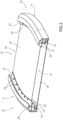
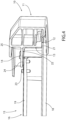
Figures 2 and3 are two perspective and schematic views, with parts in cross-section and parts removed for clarity, of a detail of the car ofFigure 1 ; and -
Figure 4 is a perspective and schematic view, on an enlarged scale and with parts removed for clarity, of a detail ofFigures 2 and3 . - With reference to
figure 1 , the number 1 denotes, in its entirety, a car, in particular a high-performance sports car, comprising asupport frame 2 defining at least part of alower floor 3 of the car 1, and apassenger compartment 4 mounted on theframe 2 and projecting upwards from thefloor 3 itself. - The car 1 further comprises a powermotor 5 of the known type, which is mounted at the centre of a
rear zone 6 of theframe 2, in particular parallel to a direction 7 of advancement of the car 1, and is connected in a known way with tworear drive wheels 8 of the car 1 itself. - The
passenger compartment 4 is provided with two access doors 9, each of which extends above an under-door side member 10 with elongated shape defining part of theframe 2. - According to what is shown in
Figures 2 ,3 , and4 , eachside member 10 comprises ametal section bar 11, which has a curvilinear shape with concavity facing thesection bar 11 of theother side member 10, and is defined, in this case, by an IPE beam. - The
section bar 11 is limited by alower face 12, is also limited by aside face 13 facing thesection bar 11 of theother side member 10, and is provided with afixing flange 14 projecting from an intermediate point of theface 13 towards thesection bar 11 of theother side member 10. - The car 1 further comprises a
battery pack 15, which is arranged between theside members 10, and comprises, in turn, a box-shaped containingbody 16 and a plurality ofbattery modules 17 accommodated inside thebody 16 itself. - The
body 16 has a substantially flatlower plate 18, and anupper lid 19 with a substantially parallelepiped shape. - The
plate 18 is fixed to theface 12 of eachsection bar 11 by means of a relative plurality of fastening screws/bolts 20 and with the interposition of arelative gasket 21. - The
lid 19 is fixed to alower face 22 of eachflange 14 by means of a relative plurality of fastening screws/bolts 23 and with the interposition of arelative gasket 24. - Each
section bar 11 defines, together with theplate 18, with thelid 19, and with therelative gaskets housing chamber 25 for cables and/or electric and/or electronic components (not shown) and/or for operating fluid supplying ducts (not shown). - The integration between the under-
door side members 10 and the box-shaped containingbody 16 of thebattery pack 15 gives the support frame 2 a relatively simple and lightweight structure compatible with the performance required of a car, in particular a high-performance sports car.
Claims (10)
- A car comprising a passenger compartment (4); two access doors (9) allowing access to the passenger compartment (4); a support frame (2), which defines at least part of a lower floor (3) of the car and comprises, in turn, two under-door side members (10), each mounted under a relative access door (9) and comprising a section bar (11) with an elongated shape; and a battery pack (15) comprising a box-shaped containing body (16) and a plurality of battery modules (17) accommodated inside the box-shaped containing body (16); and characterized in that the box-shaped containing body (16) of the battery pack (15) is mounted between and is fixed to the two under-door side members (10).
- The car according to claim 1, wherein each under-door side member (10) is provided with a fixing flange (14) projecting from the relative section bar (11) towards the other under-door side member (10); the box-shaped containing body (16) being fixed to the section bar (11) and to the fixing flange (14) of each under-door side member (10).
- The car according to claim 2 and further comprising first fixing means (20) to connect the box-shaped containing body (16) and the section bar (11) of each under-door side member (10) to one another and second fixing means (23) to connect the box-shaped containing body (16) and the fixing flange (14) of each under-door side member (10) to one another (10).
- The car according to claim 2 or 3, wherein the section bar (11) of each under-door side member (10) is delimited by a lower face (12) and by a side face (13) facing the other under-door side member (10) and provided with the relative fixing flange (14); the box-shaped containing body (16) being fixed to the lower face (12) of each section bar (11) and to a lower face (22) of each fixing flange (14).
- The car according to any one of the claims from 2 to 4, wherein the box-shaped containing body (16) is fixed to the section bar (11) of each under-door side member (10) with the interposition of a relative first gasket (21).
- The car according to any one of the claims from 2 to 5, wherein the box-shaped containing body (16) is fixed to the fixing flange (14) of each under-door side member (10) with the interposition of a relative second gasket (24).
- The car according to claims 5 and 6, wherein the box-shaped containing body (16) comprises a lower plate (18) fixed to the section bars (11) of the two under-door side members (10) through the interposition of said first gaskets (21) and an upper lid (19), which is fixed to the lower plate (18) and is further fixed to the fixing flanges (14) of the two under-door side members (10) through the interposition of said second gaskets (24).
- The car according to claim 7, wherein each section bar (11) defines, together with the lower plate (18), the upper lid (19) and the relative first and second gaskets (21, 24), a relative housing chamber (25) for cables and/or electric and/or electronic components and/or operating fluid supplying ducts.
- The car according to any one of the preceding claims, wherein each under-door side member (10) has a curved shape with a concavity facing the other under-door side member (10).
- The car according to any one of the preceding claims, wherein the section bar (11) of each under-door side member (10) has the shape of an IPE beam.
Applications Claiming Priority (1)
| Application Number | Priority Date | Filing Date | Title |
|---|---|---|---|
| IT102023000026565A IT202300026565A1 (en) | 2023-12-13 | 2023-12-13 | CAR WITH BATTERY INTEGRATED IN THE DOOR SIDES |
Publications (1)
| Publication Number | Publication Date |
|---|---|
| EP4574494A1 true EP4574494A1 (en) | 2025-06-25 |
Family
ID=90363574
Family Applications (1)
| Application Number | Title | Priority Date | Filing Date |
|---|---|---|---|
| EP24219033.8A Pending EP4574494A1 (en) | 2023-12-13 | 2024-12-11 | Car with battery integrated in the under-door side members |
Country Status (3)
| Country | Link |
|---|---|
| US (1) | US20250196608A1 (en) |
| EP (1) | EP4574494A1 (en) |
| IT (1) | IT202300026565A1 (en) |
Citations (3)
| Publication number | Priority date | Publication date | Assignee | Title |
|---|---|---|---|---|
| US10486516B2 (en) * | 2017-05-31 | 2019-11-26 | Toyota Jidosha Kabushiki Kaisha | Battery mounting structure |
| DE102020133961A1 (en) * | 2020-12-17 | 2022-06-23 | Bayerische Motoren Werke Aktiengesellschaft | Energy storage floor assembly for an electrically driven motor vehicle |
| US20230026490A1 (en) * | 2021-07-16 | 2023-01-26 | Volvo Car Corporation | Structural Battery for an Electric Vehicle |
-
2023
- 2023-12-13 IT IT102023000026565A patent/IT202300026565A1/en unknown
-
2024
- 2024-12-11 EP EP24219033.8A patent/EP4574494A1/en active Pending
- 2024-12-12 US US18/978,489 patent/US20250196608A1/en active Pending
Patent Citations (3)
| Publication number | Priority date | Publication date | Assignee | Title |
|---|---|---|---|---|
| US10486516B2 (en) * | 2017-05-31 | 2019-11-26 | Toyota Jidosha Kabushiki Kaisha | Battery mounting structure |
| DE102020133961A1 (en) * | 2020-12-17 | 2022-06-23 | Bayerische Motoren Werke Aktiengesellschaft | Energy storage floor assembly for an electrically driven motor vehicle |
| US20230026490A1 (en) * | 2021-07-16 | 2023-01-26 | Volvo Car Corporation | Structural Battery for an Electric Vehicle |
Also Published As
| Publication number | Publication date |
|---|---|
| US20250196608A1 (en) | 2025-06-19 |
| IT202300026565A1 (en) | 2025-06-13 |
Similar Documents
| Publication | Publication Date | Title |
|---|---|---|
| US9987912B2 (en) | Vehicle body rear structure | |
| US11208152B2 (en) | Vehicle body side section structure | |
| US20220016966A1 (en) | Energy Storage Underbody for a Motor Car Body-in-White | |
| EP3647163A1 (en) | Vehicle front portion structure | |
| US10597081B2 (en) | Vehicle front portion structure | |
| US11201370B2 (en) | Battery housing for a vehicle battery and chassis for an electric vehicle | |
| US8980458B2 (en) | Battery casing | |
| US11780336B2 (en) | Battery assembly | |
| US10964984B2 (en) | Battery installation for an at least partially electrically operated motor vehicle | |
| WO2023016106A1 (en) | Lower vehicle body rear structure and vehicle | |
| US10167019B2 (en) | Automobile vehicle body and automobile vehicle body manufacturing method | |
| US8029045B2 (en) | Crossbeam for a motor vehicle | |
| US20190016388A1 (en) | Vehicle front portion structure | |
| US12065030B2 (en) | Rear vehicle-body structure | |
| US11355809B2 (en) | Vehicle substructure for battery case | |
| US9073428B2 (en) | Supporting structure for vehicle control unit | |
| US20210101464A1 (en) | Vehicle substructure | |
| US10737729B2 (en) | Vehicle | |
| US20230264752A1 (en) | Rear vehicle-body structure | |
| CN113799882A (en) | Vehicle floor structure | |
| US9944212B2 (en) | Laminated panel | |
| EP4574494A1 (en) | Car with battery integrated in the under-door side members | |
| EP4292848A1 (en) | Middle section structure of ctb vehicle lower body and vehicle | |
| CN116806199A (en) | Energy storage housing, motor vehicle, electric energy storage and product series | |
| JP7662817B2 (en) | Curved cross member for vehicle floor |
Legal Events
| Date | Code | Title | Description |
|---|---|---|---|
| PUAI | Public reference made under article 153(3) epc to a published international application that has entered the european phase |
Free format text: ORIGINAL CODE: 0009012 |
|
| STAA | Information on the status of an ep patent application or granted ep patent |
Free format text: STATUS: THE APPLICATION HAS BEEN PUBLISHED |
|
| AK | Designated contracting states |
Kind code of ref document: A1 Designated state(s): AL AT BE BG CH CY CZ DE DK EE ES FI FR GB GR HR HU IE IS IT LI LT LU LV MC ME MK MT NL NO PL PT RO RS SE SI SK SM TR |
|
| STAA | Information on the status of an ep patent application or granted ep patent |
Free format text: STATUS: REQUEST FOR EXAMINATION WAS MADE |
|
| 17P | Request for examination filed |
Effective date: 20251202 |