EP4574456A1 - Shear band with oblong cords for non-pneumatic tires - Google Patents
Shear band with oblong cords for non-pneumatic tires Download PDFInfo
- Publication number
- EP4574456A1 EP4574456A1 EP24219010.6A EP24219010A EP4574456A1 EP 4574456 A1 EP4574456 A1 EP 4574456A1 EP 24219010 A EP24219010 A EP 24219010A EP 4574456 A1 EP4574456 A1 EP 4574456A1
- Authority
- EP
- European Patent Office
- Prior art keywords
- cords
- oblong
- shear band
- shear
- previous
- Prior art date
- Legal status (The legal status is an assumption and is not a legal conclusion. Google has not performed a legal analysis and makes no representation as to the accuracy of the status listed.)
- Withdrawn
Links
Images



Classifications
-
- B—PERFORMING OPERATIONS; TRANSPORTING
- B60—VEHICLES IN GENERAL
- B60C—VEHICLE TYRES; TYRE INFLATION; TYRE CHANGING; CONNECTING VALVES TO INFLATABLE ELASTIC BODIES IN GENERAL; DEVICES OR ARRANGEMENTS RELATED TO TYRES
- B60C7/00—Non-inflatable or solid tyres
- B60C7/10—Non-inflatable or solid tyres characterised by means for increasing resiliency
- B60C7/102—Tyres built-up with separate rubber parts
-
- B—PERFORMING OPERATIONS; TRANSPORTING
- B60—VEHICLES IN GENERAL
- B60C—VEHICLE TYRES; TYRE INFLATION; TYRE CHANGING; CONNECTING VALVES TO INFLATABLE ELASTIC BODIES IN GENERAL; DEVICES OR ARRANGEMENTS RELATED TO TYRES
- B60C7/00—Non-inflatable or solid tyres
-
- B—PERFORMING OPERATIONS; TRANSPORTING
- B32—LAYERED PRODUCTS
- B32B—LAYERED PRODUCTS, i.e. PRODUCTS BUILT-UP OF STRATA OF FLAT OR NON-FLAT, e.g. CELLULAR OR HONEYCOMB, FORM
- B32B27/00—Layered products comprising a layer of synthetic resin
- B32B27/12—Layered products comprising a layer of synthetic resin next to a fibrous or filamentary layer
-
- B—PERFORMING OPERATIONS; TRANSPORTING
- B60—VEHICLES IN GENERAL
- B60C—VEHICLE TYRES; TYRE INFLATION; TYRE CHANGING; CONNECTING VALVES TO INFLATABLE ELASTIC BODIES IN GENERAL; DEVICES OR ARRANGEMENTS RELATED TO TYRES
- B60C1/00—Tyres characterised by the chemical composition or the physical arrangement or mixture of the composition
- B60C1/0041—Compositions of the carcass layers
-
- B—PERFORMING OPERATIONS; TRANSPORTING
- B60—VEHICLES IN GENERAL
- B60C—VEHICLE TYRES; TYRE INFLATION; TYRE CHANGING; CONNECTING VALVES TO INFLATABLE ELASTIC BODIES IN GENERAL; DEVICES OR ARRANGEMENTS RELATED TO TYRES
- B60C7/00—Non-inflatable or solid tyres
- B60C7/10—Non-inflatable or solid tyres characterised by means for increasing resiliency
- B60C7/14—Non-inflatable or solid tyres characterised by means for increasing resiliency using springs
- B60C7/146—Non-inflatable or solid tyres characterised by means for increasing resiliency using springs extending substantially radially, e.g. like spokes
-
- B—PERFORMING OPERATIONS; TRANSPORTING
- B60—VEHICLES IN GENERAL
- B60C—VEHICLE TYRES; TYRE INFLATION; TYRE CHANGING; CONNECTING VALVES TO INFLATABLE ELASTIC BODIES IN GENERAL; DEVICES OR ARRANGEMENTS RELATED TO TYRES
- B60C7/00—Non-inflatable or solid tyres
- B60C7/22—Non-inflatable or solid tyres having inlays other than for increasing resiliency, e.g. for armouring
-
- B—PERFORMING OPERATIONS; TRANSPORTING
- B60—VEHICLES IN GENERAL
- B60C—VEHICLE TYRES; TYRE INFLATION; TYRE CHANGING; CONNECTING VALVES TO INFLATABLE ELASTIC BODIES IN GENERAL; DEVICES OR ARRANGEMENTS RELATED TO TYRES
- B60C9/00—Reinforcements or ply arrangement of pneumatic tyres
- B60C9/0028—Reinforcements comprising mineral fibres, e.g. glass or carbon fibres
-
- D—TEXTILES; PAPER
- D02—YARNS; MECHANICAL FINISHING OF YARNS OR ROPES; WARPING OR BEAMING
- D02G—CRIMPING OR CURLING FIBRES, FILAMENTS, THREADS, OR YARNS; YARNS OR THREADS
- D02G3/00—Yarns or threads, e.g. fancy yarns; Processes or apparatus for the production thereof, not otherwise provided for
- D02G3/44—Yarns or threads characterised by the purpose for which they are designed
- D02G3/48—Tyre cords
-
- B—PERFORMING OPERATIONS; TRANSPORTING
- B60—VEHICLES IN GENERAL
- B60C—VEHICLE TYRES; TYRE INFLATION; TYRE CHANGING; CONNECTING VALVES TO INFLATABLE ELASTIC BODIES IN GENERAL; DEVICES OR ARRANGEMENTS RELATED TO TYRES
- B60C1/00—Tyres characterised by the chemical composition or the physical arrangement or mixture of the composition
- B60C2001/0091—Compositions of non-inflatable or solid tyres
-
- B—PERFORMING OPERATIONS; TRANSPORTING
- B60—VEHICLES IN GENERAL
- B60C—VEHICLE TYRES; TYRE INFLATION; TYRE CHANGING; CONNECTING VALVES TO INFLATABLE ELASTIC BODIES IN GENERAL; DEVICES OR ARRANGEMENTS RELATED TO TYRES
- B60C9/00—Reinforcements or ply arrangement of pneumatic tyres
- B60C9/18—Structure or arrangement of belts or breakers, crown-reinforcing or cushioning layers
- B60C9/20—Structure or arrangement of belts or breakers, crown-reinforcing or cushioning layers built-up from rubberised plies each having all cords arranged substantially parallel
- B60C2009/2012—Structure or arrangement of belts or breakers, crown-reinforcing or cushioning layers built-up from rubberised plies each having all cords arranged substantially parallel with particular configuration of the belt cords in the respective belt layers
- B60C2009/2016—Structure or arrangement of belts or breakers, crown-reinforcing or cushioning layers built-up from rubberised plies each having all cords arranged substantially parallel with particular configuration of the belt cords in the respective belt layers comprising cords at an angle of 10 to 30 degrees to the circumferential direction
-
- B—PERFORMING OPERATIONS; TRANSPORTING
- B60—VEHICLES IN GENERAL
- B60C—VEHICLE TYRES; TYRE INFLATION; TYRE CHANGING; CONNECTING VALVES TO INFLATABLE ELASTIC BODIES IN GENERAL; DEVICES OR ARRANGEMENTS RELATED TO TYRES
- B60C9/00—Reinforcements or ply arrangement of pneumatic tyres
- B60C9/18—Structure or arrangement of belts or breakers, crown-reinforcing or cushioning layers
- B60C9/20—Structure or arrangement of belts or breakers, crown-reinforcing or cushioning layers built-up from rubberised plies each having all cords arranged substantially parallel
- B60C2009/2061—Physical properties or dimensions of the belt coating rubber
- B60C2009/2064—Modulus; Hardness; Loss modulus or "tangens delta"
-
- B—PERFORMING OPERATIONS; TRANSPORTING
- B60—VEHICLES IN GENERAL
- B60C—VEHICLE TYRES; TYRE INFLATION; TYRE CHANGING; CONNECTING VALVES TO INFLATABLE ELASTIC BODIES IN GENERAL; DEVICES OR ARRANGEMENTS RELATED TO TYRES
- B60C9/00—Reinforcements or ply arrangement of pneumatic tyres
- B60C9/18—Structure or arrangement of belts or breakers, crown-reinforcing or cushioning layers
- B60C9/20—Structure or arrangement of belts or breakers, crown-reinforcing or cushioning layers built-up from rubberised plies each having all cords arranged substantially parallel
- B60C2009/2074—Physical properties or dimension of the belt cord
- B60C2009/2077—Diameters of the cords; Linear density thereof
-
- B—PERFORMING OPERATIONS; TRANSPORTING
- B60—VEHICLES IN GENERAL
- B60C—VEHICLE TYRES; TYRE INFLATION; TYRE CHANGING; CONNECTING VALVES TO INFLATABLE ELASTIC BODIES IN GENERAL; DEVICES OR ARRANGEMENTS RELATED TO TYRES
- B60C9/00—Reinforcements or ply arrangement of pneumatic tyres
- B60C9/18—Structure or arrangement of belts or breakers, crown-reinforcing or cushioning layers
- B60C9/20—Structure or arrangement of belts or breakers, crown-reinforcing or cushioning layers built-up from rubberised plies each having all cords arranged substantially parallel
- B60C9/22—Structure or arrangement of belts or breakers, crown-reinforcing or cushioning layers built-up from rubberised plies each having all cords arranged substantially parallel the plies being arranged with all cords disposed along the circumference of the tyre
- B60C2009/2228—Structure or arrangement of belts or breakers, crown-reinforcing or cushioning layers built-up from rubberised plies each having all cords arranged substantially parallel the plies being arranged with all cords disposed along the circumference of the tyre characterised by special physical properties of the zero degree plies
- B60C2009/2233—Modulus of the zero degree ply
-
- B—PERFORMING OPERATIONS; TRANSPORTING
- B60—VEHICLES IN GENERAL
- B60C—VEHICLE TYRES; TYRE INFLATION; TYRE CHANGING; CONNECTING VALVES TO INFLATABLE ELASTIC BODIES IN GENERAL; DEVICES OR ARRANGEMENTS RELATED TO TYRES
- B60C9/00—Reinforcements or ply arrangement of pneumatic tyres
- B60C9/18—Structure or arrangement of belts or breakers, crown-reinforcing or cushioning layers
- B60C9/20—Structure or arrangement of belts or breakers, crown-reinforcing or cushioning layers built-up from rubberised plies each having all cords arranged substantially parallel
- B60C9/22—Structure or arrangement of belts or breakers, crown-reinforcing or cushioning layers built-up from rubberised plies each having all cords arranged substantially parallel the plies being arranged with all cords disposed along the circumference of the tyre
- B60C2009/2238—Physical properties or dimensions of the ply coating rubber
- B60C2009/2242—Modulus; Hardness; Loss modulus or "tangens delta"
-
- B—PERFORMING OPERATIONS; TRANSPORTING
- B60—VEHICLES IN GENERAL
- B60C—VEHICLE TYRES; TYRE INFLATION; TYRE CHANGING; CONNECTING VALVES TO INFLATABLE ELASTIC BODIES IN GENERAL; DEVICES OR ARRANGEMENTS RELATED TO TYRES
- B60C9/00—Reinforcements or ply arrangement of pneumatic tyres
- B60C9/18—Structure or arrangement of belts or breakers, crown-reinforcing or cushioning layers
- B60C9/20—Structure or arrangement of belts or breakers, crown-reinforcing or cushioning layers built-up from rubberised plies each having all cords arranged substantially parallel
- B60C9/22—Structure or arrangement of belts or breakers, crown-reinforcing or cushioning layers built-up from rubberised plies each having all cords arranged substantially parallel the plies being arranged with all cords disposed along the circumference of the tyre
- B60C2009/2252—Physical properties or dimension of the zero degree ply cords
- B60C2009/2257—Diameters of the cords; Linear density thereof
-
- B—PERFORMING OPERATIONS; TRANSPORTING
- B60—VEHICLES IN GENERAL
- B60C—VEHICLE TYRES; TYRE INFLATION; TYRE CHANGING; CONNECTING VALVES TO INFLATABLE ELASTIC BODIES IN GENERAL; DEVICES OR ARRANGEMENTS RELATED TO TYRES
- B60C7/00—Non-inflatable or solid tyres
- B60C7/10—Non-inflatable or solid tyres characterised by means for increasing resiliency
- B60C7/14—Non-inflatable or solid tyres characterised by means for increasing resiliency using springs
- B60C7/143—Non-inflatable or solid tyres characterised by means for increasing resiliency using springs having a lateral extension disposed in a plane parallel to the wheel axis
-
- B—PERFORMING OPERATIONS; TRANSPORTING
- B60—VEHICLES IN GENERAL
- B60C—VEHICLE TYRES; TYRE INFLATION; TYRE CHANGING; CONNECTING VALVES TO INFLATABLE ELASTIC BODIES IN GENERAL; DEVICES OR ARRANGEMENTS RELATED TO TYRES
- B60C9/00—Reinforcements or ply arrangement of pneumatic tyres
- B60C9/0042—Reinforcements made of synthetic materials
-
- B—PERFORMING OPERATIONS; TRANSPORTING
- B60—VEHICLES IN GENERAL
- B60C—VEHICLE TYRES; TYRE INFLATION; TYRE CHANGING; CONNECTING VALVES TO INFLATABLE ELASTIC BODIES IN GENERAL; DEVICES OR ARRANGEMENTS RELATED TO TYRES
- B60C9/00—Reinforcements or ply arrangement of pneumatic tyres
- B60C9/0064—Reinforcements comprising monofilaments
-
- B—PERFORMING OPERATIONS; TRANSPORTING
- B60—VEHICLES IN GENERAL
- B60C—VEHICLE TYRES; TYRE INFLATION; TYRE CHANGING; CONNECTING VALVES TO INFLATABLE ELASTIC BODIES IN GENERAL; DEVICES OR ARRANGEMENTS RELATED TO TYRES
- B60C9/00—Reinforcements or ply arrangement of pneumatic tyres
- B60C9/18—Structure or arrangement of belts or breakers, crown-reinforcing or cushioning layers
- B60C9/1835—Rubber strips or cushions at the belt edges
Definitions
- the present disclosure relates generally to vehicle tires and, more particularly, to a shear band for non-pneumatic tires with a high compressive stiffness to reduce rolling resistance.
- the pneumatic tire has been the solution of choice for vehicular mobility for over a century.
- Pneumatic tires are efficient at carrying loads, because all of the tire structure is involved in carrying the load.
- Pneumatic tires are also desirable because they have low contact pressure, resulting in lower wear on roads due to the distribution of the load of the vehicle.
- Pneumatic tires also have low stiffness, which ensures a comfortable ride in a vehicle.
- the primary drawback to a pneumatic tire is that it requires compressed fluid. A conventional pneumatic tire is rendered useless after a complete loss of inflation pressure.
- a tire designed to operate without inflation pressure may eliminate many of the problems and compromises associated with a pneumatic tire. Neither pressure maintenance nor pressure monitoring is required.
- Non pneumatic tires are typically defined by their load carrying efficiency.
- Bottom loaders are essentially rigid structures that carry a majority of the load in the portion of the structure below the hub.
- Top loaders are designed so that all of the structure is involved in carrying the load. Top loaders thus have a higher load carrying efficiency than bottom loaders, allowing a design that has less mass.
- Non-pneumatic tires typically have a shear band made from rubber materials sandwiched between at least two layers of inextensible belts or membranes. The use of rubber in a shear band may significantly increase the cost, weight and rolling resistance of the non-pneumatic tire.
- the invention relates to a shear band in accordance with claim 1, to a non-pneumatic tire in accordance with claim 13, and to a method in accordance with claim 14.
- a non-pneumatic tire having a shear band that is constructed to increase a volume of reinforcement materials, which may have little or no hysteresis.
- the volume of reinforcement materials in a shear band is increased using oblong cords having a greater lateral width than a radial height.
- oblong cords may be rectangular in cross section and be closely packed in parallel layers. A thickness of a compound interspacing the oblong cords may be reduced by selecting a compound with a sufficient stiffness.
- the oblong cords may be provided as monofilaments constructed from a single material, or as multi-filament cords including a plurality of elongated glass, aromatic polyamide (aramid) and/or carbon-fiber filaments embedded in a resin matrix.
- monofilaments constructed from a single material
- multi-filament cords including a plurality of elongated glass, aromatic polyamide (aramid) and/or carbon-fiber filaments embedded in a resin matrix.
- the non-pneumatic tire includes a central rim for receiving a vehicle wheel therein or otherwise coupling the tire to a vehicle, a connecting web including a plurality of spokes coupled to the central rim and extending radially outward therefrom and a shear band circumscribing the connecting web and coupled thereto.
- the shear band includes a plurality of oblong cords arranged in parallel layers, each of the oblong cords having a cross section defining a greater lateral width than a radial height.
- “Circumferential” means lines or directions extending along the perimeter of the surface of the annular tread perpendicular to the axial direction.
- Core means one of 1) a plurality of filaments twisted or otherwise joined together to form an elongated strip of material; 2) a single filament (monofilament) with or without a coating; or 3) a narrow strip of material with or without twist and/or coating.
- Equatorial plane means a plane perpendicular to an axis of rotation of a tire and passing through the center of its tread.
- “Inextensible” means that a given layer or reinforcement has an extensional stiffness greater than 172.4 MPa (25 Ksi).
- “Monofilament” means a cord having only one filament.
- Ring and radially means directions radially toward or away from the axis of rotation of the tire.
- the central rim 106 may be of any suitable design and material for receiving a wheel of a vehicle therein, or otherwise coupling the non-pneumatic tire 100 to a vehicle.
- the central rim 106 may be constructed generally as a cylindrical component formed from rubber, plastic or carbon fibers.
- the cylindrical rim 106 may define a central axis of rotation (not shown) for the non-pneumatic tire 100.
- the connecting web 104 is disposed radially outward of the central rim 106 and may include a plurality of spokes 112 that extend radially outward from the central rim to the shear band 102.
- the connecting web 104 includes two sets of circumferentially aligned spokes 112 at lateral ends of the non-pneumatic tire 100.
- the shear band 102 is an annular structure that is located radially outward of the connecting web 104 and radially inward of a tread portion 118 of the non-pneumatic tire 100.
- the tread portion 118 may or may not include grooves or other patterns for contacting a road surface.
- the tread portion118 may include elements such as ribs, blocks, lugs and sipes to improve a grip or other performance characteristics of the non-pneumatic tire 100.
- a layer or tread rubber 120 may be adhered to a radially outer surface of the shear band 102.
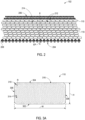
- the oblong cords 110 are arranged in a plurality of parallel layers 212.
- the parallel layers 212 allow for the oblong cords 110 to be closely packed, thereby providing a relatively large volume of reinforcement materials to the shear band 102.
- the oblong cords 110 in each of the parallel layers 212 are laterally staggered from the oblong cords 110 in adjacent layers 212. This arrangement may provide a relatively stiff shear band 102.
- the oblong cords 110 may be arranged in parallel radial columns (not shown) as well as in parallel layers 212.
- An elastomeric compound 214 may be provided interspacing the oblong cords 110.
- the elastomeric compound 214 may be formed from a mix of various ingredients selected to provide a desired stiffness or other characteristics to the shear band 102.
- the compound 214 may have a shear modulus or modulus of rigidity G' 1% RPA in the range of from 1.0 MPa to 42 MPa.
- the modulus of rigidity G' 1% RPA may be in the range of from 0.5 MPa to 15 MPa, and more preferably in the range of from 3 MPa to 7 MPa.
- the oblong cord 110 has a lateral width "W" that is greater than a radial height "H.”
- the width "W” may be in the range of 0.7 mm to 38 mm while the height "H” may be in the range of 0.1 mm to 18 mm.
- the ratio of width to height (W/H) of the oblong cords 110 is at least 1.1 or at least 1.3 or at least 1.5 or at least 2.
- the lateral and radial directions are described with respect to the orientation of the oblong cords 110 as arranged in FIG. 2 , i.e., with the width "W” parallel to a lateral direction and the height "H” parallel with a radial direction.
- the larger “W” with respect to the height “H” increases a lateral bending stiffness of the oblong cord 110 and a shear band 102 constructed with the oblong cords 110.
- the oblong cords 110 may be arranged in other orientations, such as inclined and/or orthogonal to the orientation illustrated.
- the oblong cord 110 illustrated in FIG. 3A includes lower and upper walls 302, 304, as well as sidewalls 306, 308 that are substantially flat.
- Rounded corners 310 are defined at the intersection between the walls 302, 304, 306, 308 such that the oblong cord 110 may be substantially free of sharp corners.
- the rounded corners 310 may each have a radius "R,” which may be less than half of the radial height "H.”
- the resin matrix 316 may include a cross-linkable or curable resin, which may be cross-linked or cured by exposure to UV radiation or heat, or by other methods recognized in the art.
- the resins may be, e.g., an epoxy vinyl ester type, an epoxy bisphenol type, epoxy bisphenol A type and/or a mixture of epoxy vinyl ester type and epoxy bisphenol type resins.
- the oblong cord 110 is constructed of a nylon resin matrix 316 reinforced with glass or carbon filaments 314.
- the oblong cord 110 may be constructed as a monofilament of a single material.
- the oblong cord may exhibit the same cross section as illustrated in FIG. 3A , but may be constructed of a single material such as nylon, polyester, aromatic polyamide or carbon fiber.
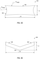
- FIGS. 3B through 3E other example embodiments of oblong cords 320, 322, 324 and 326 are illustrated in cross-section, each with a lateral width "W" greater than a radial height "H.”
- the oblong cord 320 illustrated in FIG. 3B has an obround cross-section, which includes has two semicircular sides 332, 334 connected by flat lower and upper parallel sides 336, 338.
- the semicircular sides 332, 334 are defined by rounded corners 340 having a radius "R" equal to half the radial height "H.”
- the oblong cord 320 may have a width "W" to height "H” ratio in the range of 2 to 5 in some embodiments.
- the oblong cord 322 may have a standard rectangular cross-section with sharp corners 342, e.g., corners having a radius "R" equal to zero.
- the oblong cord 324 ( FIG. 3D ) may have concave sides 344 and 346.
- the concave sides 344 that extend across the radial height "H” may have a relatively small minor radius R minor and the concave sides 346 that extend across the lateral width "W" may a relatively large major radius R major .
- the minor and major radii R minor and R major may be considered “negative” since centers of the radii R minor and R major are disposed exterior to the cross section and define concave portions of the oblong cord 324.
- the oblong cord 326 may have an irregular cross-section, such as the chevron shaped cross-section illustrated.
- the chevron-shaped cross section includes two arms 348, 350 extending from a vertex 352 in opposed directions.
- the chevron-shaped cross-section may allow oblong cords 326 to interlock with one another when arranged in parallel layers.
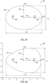
- the oblong cord 354 may have a substantially elliptical cross section defining a perimeter 354.
- Focal points 364 of the ellipse are located at a distance "c" from the origin (0, 0), and the distance "c" may be calculated using Equation 2 below.
- c a 2 ⁇ b 2
- An eccentricity "e” of the ellipse generally describes how flat or round the shape of the ellipse is. Generally, the more circular the ellipse is, the closer “e” will be to zero (0), and the flatter the ellipse is, the closer “e” will be to one (1).
- the oblong cord 356 may have an irregular elliptical (e.g., egg shaped) cross section defining a perimeter 374.
- the perimeter 374 is centered at the origin (0, 0) of the Cartesian coordinate plane, and may be expressed by Equation 4 below.
- "a” represents a length of a semi-major axis 376
- "b” represents a length of a semi-minor axis 378
- t is a constant much less than "a.”
- each of the oblong cords 110 ( FIG. 3A ), 320 ( FIG. 3B ), 322 ( FIG. 3C ), 324 ( FIG. 3D ), 326, ( FIG. 3E ), 354 ( FIG. 3F ) and 356 ( FIG. 3G ), it should be appreciated that variations from these idealized shapes are contemplated, e.g., due to manufacturing tolerances and irregularities, without departing from the scope of the disclosure. Additionally, each of the oblong cords 110, 320, 322, 324, 326, 354, 356 (and any of the other cords described herein) may have a surface finish, from smooth to rough, which may promote adhesion with one another or the compound 214 ( FIG. 2 ).
- the surface finish may cause the cords to vary from the idealized or mathematical shapes described above.
- the oblong cords 320, 322, 324, 326, 354, 356 (and any of the other cords described herein) may be constructed either as a monofilament of a single material (e.g., nylon, polyester, glass, aromatic polyamide, carbon fibers), or as a multifilament cord including a plurality of elongated filaments (e.g., glass, aromatic polyamide or carbon fibers) embedded in a resin matrix, twisted together or otherwise adhered to one another in an oblong shape.
- a shear band 402 including one or more inner belt layers 404 constructed of aromatic polyamide cords 406, or another material that is dissimilar from the outer belt layer(s) 206.
- the aromatic polyamide cords 406 provide temperature chemical resistance to the shear band 402 or may offer other performance characteristics.
- aromatic polyamides, such as aramid may form cords 406 that have high tensile stiffness. Arranging aromatic polyamide cords 406 at the very bottom (near a radially innermost edge) of the shear band 402 provides a maximum benefit of their high tensile stiffness since the radially innermost edge of the shear band 402 is subjected to tensile forces in operation.
- cords 406 will reinforce the shear band 402 and resist these tensile forces.
- the cords 406 may be constructed of nylon resins. Nylons are aliphatic polyamides, which may shrink when heated, e.g., by operational stresses. The ability of the cords 406 to shrink may provide resistance against growth of the shear band 402 and tires constructed with the shear band 402.
- the outer belt layer 206 may be constructed of elongated steel wire cords 208 embedded in an elastomeric coating as described above.
- the aromatic polyamide cords 406 may be a larger in diameter than the steel wire cords 208, and may be tackified to maintain the aromatic polyamide cords 406 in position as the shear band 402 is constructed.
- the aromatic polyamide cords 406 (or any of the other cords described herein) may be tackified by various methods recognized in the art such as coating the cord 406 in an aqueous blend of rosin and rubber lattices, or with a solvent solution or emulsion of an un-vulcanized rubber compound.
- the aromatic polyamide cords 406 may be inclined in range of -25 degrees to 25 degrees, -10 degrees to 10 degrees, and/or -20 degrees to 30 degrees from an equatorial plane EP ( FIG. 2 ) of the tire.
- the shear band 402 includes one or more parallel layers 212 of oblong cords 110 as described above.
- the oblong cords 110 may be replaced with another one of the oblong cords 320 ( FIG. 3B ), 322 ( FIG. 3C ), 324 ( FIG. 3D ), 326 ( FIG. 3E ), 354 ( FIG. 3F ) or 356 ( FIG. 3F ) described above, or a combination of the oblong cords 110, 320, 322, 324, 326, 354, 356 with one another without departing from the scope of the disclosure.
- a shear band 502 including a pair of end belts 504 overlying lateral edges 506a, 506b of the outer belt layer 206.
- the end belts 504 include wire cords 508 or other filaments extending an angle in the range of 0 to ⁇ 10 degrees, and in some embodiments in the range of 0 to ⁇ 5 degrees relative to the equatorial plane EP ( FIG. 2 ).
- the end belts 504 may restrict movement of the outer belt layers 206 at the lateral edges 506a, 506b and thereby reduce stress, fatigue and heat generation when the shear band 502 is in use. Reducing stresses may reduce the risk of edge separation of the outer belts 206 from adjacent layers.
- the shear band 502 may further include one or more parallel layers 212 of oblong cords 110 and one or more inner belt layers 404 as described above.
- the manufacturing implement 600 includes a press roller 602 and a shaping roller 604.
- the shaping roller 604 may include a circumferential notch 606 defined therein, with a width and depth sized and shaped similarly to the lateral width "W" and radial height "H" of the desired oblong cord.
- the circumferential notch 606 is generally rectangular and may be employed to form oblong cords 110.
- the circumferential notch 606 may be sized or shaped to form any of the other oblong cords 320, 322, 324, 326, 354, 356 or any of the other multi-filament cords described herein.
- One or both of the press roller 602 and the shaping roller 604 may include a heater, e.g., a resistive heater (not shown) therein, or in other embodiments, distinct heaters (not shown) may be provided adjacent the rollers 602, 604.
- the press roller 602 and the shaping roller 604 engage one another and may be rotated in opposite directions, e.g., in the directions of arrows 608, 610, to feed a plurality of resin coated filament bundles 612 through the circumferential notch 606.
- the filament bundles 612 may include one or more filaments 314 ( FIG. 3 ), which may include glass filaments, aromatic polyamide filaments and/or carbon fiber filaments as described above.
- the multifilament oblong cords 110, 320, 322, 324, 326, 354, 356 may be constructed using pultrusion techniques and equipment.
- Pultrusion is a processing technique of forming and manufacturing a continuous length of fiber-reinforced polymer (FRP) by pulling a mix of reinforced fibers (e.g., glass, aromatic polyamide and/or carbon fibers) and liquid resin through a heated die (not shown). The process results in cords with a constant section, such as pipes, rods, beams, and/or any of the shapes illustrated in FIGS. 3A through 3F .
- the shape of the heated die along with type of resin matrix may be varied to produce oblong cords 110, 320, 322, 324, 326, 354, 356 with the desired performance characteristics.
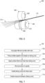
- the procedure 700 begins at step 702 where glass filament bundles are coated with a resin.
- the bundles may be then be pressed together (step 704) and shaped into an oblong cord.
- the bundles may be pressed together with a shaping roller or with a die in a pultrusion manufacturing facility.
- step 706 a surface finish is applied and the oblong cord is heat treated. It should be appreciated that steps 702, 704 and 706 may be performed sequentially, simultaneously and in different orders than those indicated.
- step 708 the finished oblong cords are wound on spools for storage or transport.
- step 708 may be omitted and the procedure 700 proceeds directly to step 710 where the oblong cords are installed into a shear band of a non-pneumatic tire assembly.
- the oblong cords may be installed in parallel circumferential layers, and the oblong cords in each layer may be laterally staggered with respect to oblong cords in adjacent layers.
- a compound may then be installed between the oblong cords in the shear band.
- the tire assembly may be completed by installing upper and/or lower belts to the shear band, installing a tread and/or by installing the shear band onto a central rim and connecting web.
Landscapes
- Engineering & Computer Science (AREA)
- Mechanical Engineering (AREA)
- Textile Engineering (AREA)
- Tires In General (AREA)
Abstract
A shear band for a non-pneumatic tire is disclosed. The shear band comprises a plurality of oblong cords arranged in parallel layers, each of the oblong cords having a cross section defining a greater lateral width than a radial height. The shear band may be used in a non-pneumatic tire comprising a central rim for coupling the tire to a vehicle wheel, a connecting web including a plurality of spokes coupled to the central rim and extending radially outward therefrom. The shear band circumscribes the connecting web and is coupled thereto. Also, a method of manufacturing a shear band for a non-pneumatic tire is disclosed. The method comprises: pressing a plurality of filaments together to form oblong cords having a cross section defining a greater lateral width than a radial height; heat treating the oblong cords; and installing the oblong cords in a plurality of parallel circumferential layers to form the shear band.
Description
- The present disclosure relates generally to vehicle tires and, more particularly, to a shear band for non-pneumatic tires with a high compressive stiffness to reduce rolling resistance.
- The pneumatic tire has been the solution of choice for vehicular mobility for over a century. Pneumatic tires are efficient at carrying loads, because all of the tire structure is involved in carrying the load. Pneumatic tires are also desirable because they have low contact pressure, resulting in lower wear on roads due to the distribution of the load of the vehicle. Pneumatic tires also have low stiffness, which ensures a comfortable ride in a vehicle. The primary drawback to a pneumatic tire is that it requires compressed fluid. A conventional pneumatic tire is rendered useless after a complete loss of inflation pressure.
- A tire designed to operate without inflation pressure may eliminate many of the problems and compromises associated with a pneumatic tire. Neither pressure maintenance nor pressure monitoring is required. Non pneumatic tires are typically defined by their load carrying efficiency. "Bottom loaders" are essentially rigid structures that carry a majority of the load in the portion of the structure below the hub. "Top loaders" are designed so that all of the structure is involved in carrying the load. Top loaders thus have a higher load carrying efficiency than bottom loaders, allowing a design that has less mass.
- The purpose of a shear band in a non-pneumatic tire is to transfer the load from contact with the ground through tension in the spokes or connecting web to the central rim, creating a top loading structure. When the shear band deforms, its preferred form of deformation is shear over bending. Non-pneumatic tires typically have a shear band made from rubber materials sandwiched between at least two layers of inextensible belts or membranes. The use of rubber in a shear band may significantly increase the cost, weight and rolling resistance of the non-pneumatic tire.
- The invention relates to a shear band in accordance with claim 1, to a non-pneumatic tire in accordance with claim 13, and to a method in accordance with claim 14.
- Dependent claims refer to preferred embodiments of the invention.
- Disclosed is a non-pneumatic tire having a shear band that is constructed to increase a volume of reinforcement materials, which may have little or no hysteresis. The volume of reinforcement materials in a shear band is increased using oblong cords having a greater lateral width than a radial height. In some embodiments, oblong cords may be rectangular in cross section and be closely packed in parallel layers. A thickness of a compound interspacing the oblong cords may be reduced by selecting a compound with a sufficient stiffness. The oblong cords may be provided as monofilaments constructed from a single material, or as multi-filament cords including a plurality of elongated glass, aromatic polyamide (aramid) and/or carbon-fiber filaments embedded in a resin matrix.
- Disclosed is also a non-pneumatic tire. The non-pneumatic tire includes a central rim for receiving a vehicle wheel therein or otherwise coupling the tire to a vehicle, a connecting web including a plurality of spokes coupled to the central rim and extending radially outward therefrom and a shear band circumscribing the connecting web and coupled thereto. The shear band includes a plurality of oblong cords arranged in parallel layers, each of the oblong cords having a cross section defining a greater lateral width than a radial height.
- The following definitions are applicable to the present invention.
- "Axial" and "axially" means lines or directions that are parallel to the axis of rotation of the tire.
- "Circumferential" means lines or directions extending along the perimeter of the surface of the annular tread perpendicular to the axial direction.
- "Cord" means one of 1) a plurality of filaments twisted or otherwise joined together to form an elongated strip of material; 2) a single filament (monofilament) with or without a coating; or 3) a narrow strip of material with or without twist and/or coating.
- "Equatorial plane (EP)" means a plane perpendicular to an axis of rotation of a tire and passing through the center of its tread.
- "Inextensible" means that a given layer or reinforcement has an extensional stiffness greater than 172.4 MPa (25 Ksi).
- "Lateral" means an axial direction.
- "Monofilament" means a cord having only one filament.
- "Oblong" means a cross-sectional shape having a greater width relative to its height, or an elongated member with such a cross-section.
- "Obround" means a cross-sectional shape having two opposed semicircles connected by parallel lines tangent to their endpoints.
- "Radial" and "radially" means directions radially toward or away from the axis of rotation of the tire.
- The invention will be described by way of example and with reference to the accompanying drawings in which:
-
FIG. 1 is a cross-sectional perspective view of an example of a non-pneumatic tire including a shear band constructed with oblong cords in accordance with aspects of the present disclosure. -
FIG. 2 is an enlarged, partial cross-sectional view of the shear band ofFIG. 1 illustrating the oblong cords interposing reinforced belt layers of the shear band. -
FIG. 3A is an enlarged, cross-sectional view of an oblong cord ofFIG. 2 . -
FIGS 3B-3G are cross-sectional views of alternate embodiments of oblong cords. -
FIG. 4 is a partial, cross-sectional view of an alternate embodiment of a shear band including one or more layers of SED cord belts radially inward of a layer of oblong cords. -
FIG. 5 is a partial, cross-sectional view of an alternate embodiment of a shear band including one or more overlays disposed over lateral edges of the shear band. -
FIG. 6 is a schematic view of a manufacturing implement for forming the oblong filaments. -
FIG. 7 is a flowchart illustrating a method of manufacture for a tire assembly in accordance with aspects of the present disclosure. - Referring to
FIG. 1 , anon-pneumatic tire 100 in accordance with the present disclosure is illustrated. Thenon-pneumatic tire 100 generally includes ashear band 102, a connectingweb 104 and acentral rim 106, and may be designed as a top loading structure, so that theshear band 102 and the connectingweb 104 efficiently carry the operational loads. As described in greater detail below, theshear band 102 is constructed with a plurality ofoblong cords 110 that reinforce theshear band 102 and thereby reduce a rolling resistance of thenon-pneumatic tire 100. Preferably, the ratio of width to height of theoblong cords 110 is at least 1.1 or at least 1.3 or at least 1.5 or at least 2. - The
central rim 106 may be of any suitable design and material for receiving a wheel of a vehicle therein, or otherwise coupling thenon-pneumatic tire 100 to a vehicle. For example, thecentral rim 106 may be constructed generally as a cylindrical component formed from rubber, plastic or carbon fibers. Thecylindrical rim 106 may define a central axis of rotation (not shown) for thenon-pneumatic tire 100. The connectingweb 104 is disposed radially outward of thecentral rim 106 and may include a plurality ofspokes 112 that extend radially outward from the central rim to theshear band 102. As illustrated, the connectingweb 104 includes two sets of circumferentially alignedspokes 112 at lateral ends of thenon-pneumatic tire 100. Thespokes 112 may be curved or straight, and may have different cross-sectional designs than the generallyrectangular spokes 112 illustrated. In some embodiments, the connectingweb 104 may also include a connectingring 114 extending axially between thespokes 112. The connectingring 114 may be provided to stiffen thenon-pneumatic tire 100 in a radial direction, and may be constructed of a fabric lattice or other structure. In other embodiments, the connectingring 114 may be omitted. The connecting web 104 (including the spokes 112) may be formed of an elastic material such as a rubber or a thermoplastic elastomer. - The
shear band 102 is an annular structure that is located radially outward of the connectingweb 104 and radially inward of atread portion 118 of thenon-pneumatic tire 100. Thetread portion 118 may or may not include grooves or other patterns for contacting a road surface. The tread portion118 may include elements such as ribs, blocks, lugs and sipes to improve a grip or other performance characteristics of thenon-pneumatic tire 100. A layer or treadrubber 120 may be adhered to a radially outer surface of theshear band 102. - Referring now to
FIG. 2 , theshear band 102 is illustrated in cross section. Theshear band 102 is generally constructed of theoblong cords 110 sandwiched between one or more radially inner belt layers 204 and one or more radially outer belt layers 206. The belt layers 204, 206 may be constructed of elongatedsteel wire cords 208 embedded in an elastomeric coating. The elongatedsteel wire cords 208 in the radially inner belt layers 204 may be oriented at a first angle in a range of from 0 to ±10 degrees, 0 to ±25 degrees relative to an equatorial plane EP of the non-pneumatic tire 100 (FIG. 1 ). Similarly, the elongatedsteel wire cords 208 in the outer belt layers 206 may be oriented at a second angle in the range of 0 to ±10 degrees, 0 to ±25 degrees and/or -20 to 30 degrees relative to the equatorial plane EP. In some embodiments, the first angle and the second angle extend in opposite directions, and in other embodiments, the first and second angles extend in the same direction. Although the first and second belt layers 204, 206 are described as being constructed with elongatedsteel wire cords 208, in other embodiments, other types of inextensible reinforcement cords may substituted for the elongatedsteel wire cords 208 without departing from the scope of the disclosure. - The
oblong cords 110 are arranged in a plurality ofparallel layers 212. Theparallel layers 212 allow for theoblong cords 110 to be closely packed, thereby providing a relatively large volume of reinforcement materials to theshear band 102. As illustrated inFIG. 2 , theoblong cords 110 in each of theparallel layers 212 are laterally staggered from theoblong cords 110 inadjacent layers 212. This arrangement may provide a relativelystiff shear band 102. In other embodiments, theoblong cords 110 may be arranged in parallel radial columns (not shown) as well as inparallel layers 212. Anelastomeric compound 214 may be provided interspacing theoblong cords 110. Theelastomeric compound 214 may be formed from a mix of various ingredients selected to provide a desired stiffness or other characteristics to theshear band 102. In some embodiments, thecompound 214 may have a shear modulus or modulus of rigidity G' 1% RPA in the range of from 1.0 MPa to 42 MPa. In some preferred embodiments the modulus of rigidity G' 1% RPA may be in the range of from 0.5 MPa to 15 MPa, and more preferably in the range of from 3 MPa to 7 MPa. - Referring now to
FIG. 3A , one example embodiment of anoblong cord 110 is illustrated with a substantially rectangular cross section. Theoblong cord 110 has a lateral width "W" that is greater than a radial height "H." In some preferred embodiments, the width "W" may be in the range of 0.7 mm to 38 mm while the height "H" may be in the range of 0.1 mm to 18 mm. Preferably, the ratio of width to height (W/H) of theoblong cords 110 is at least 1.1 or at least 1.3 or at least 1.5 or at least 2. - The lateral and radial directions are described with respect to the orientation of the
oblong cords 110 as arranged inFIG. 2 , i.e., with the width "W" parallel to a lateral direction and the height "H" parallel with a radial direction. The larger "W" with respect to the height "H" increases a lateral bending stiffness of theoblong cord 110 and ashear band 102 constructed with theoblong cords 110. - In other embodiments the
oblong cords 110 may be arranged in other orientations, such as inclined and/or orthogonal to the orientation illustrated. Theoblong cord 110 illustrated inFIG. 3A includes lower andupper walls sidewalls Rounded corners 310 are defined at the intersection between thewalls oblong cord 110 may be substantially free of sharp corners. Therounded corners 310 may each have a radius "R," which may be less than half of the radial height "H." - As illustrated in
FIG. 3A , theoblong cord 110 is a multi-filament cord constructed of a plurality ofelongated filaments 314 embedded in aresin matrix 316. Theelongated filaments 314 may be constructed of glass, aromatic polyamide and/or carbon fibers, and may comprise greater than 50% of a volume of theoblong cord 110. Theresin matrix 316 may include at least one of an epoxy, nylon, polyurethane, polyester, vinyl ester, pheonolic resin and resorcinol/formaldehyde/latex (RFL) resin, and generally binds theelongated filaments 314 to one another. Theresin matrix 316 may include a cross-linkable or curable resin, which may be cross-linked or cured by exposure to UV radiation or heat, or by other methods recognized in the art. The resins may be, e.g., an epoxy vinyl ester type, an epoxy bisphenol type, epoxy bisphenol A type and/or a mixture of epoxy vinyl ester type and epoxy bisphenol type resins. In some example embodiments, theoblong cord 110 is constructed of anylon resin matrix 316 reinforced with glass orcarbon filaments 314. In other embodiments, theoblong cord 110 may be constructed as a monofilament of a single material. For example, the oblong cord may exhibit the same cross section as illustrated inFIG. 3A , but may be constructed of a single material such as nylon, polyester, aromatic polyamide or carbon fiber. - Referring now to
FIGS. 3B through 3E , other example embodiments ofoblong cords oblong cord 320 illustrated inFIG. 3B has an obround cross-section, which includes has twosemicircular sides parallel sides semicircular sides rounded corners 340 having a radius "R" equal to half the radial height "H." Theoblong cord 320 may have a width "W" to height "H" ratio in the range of 2 to 5 in some embodiments. The oblong cord 322 (FIG. 3C ) may have a standard rectangular cross-section withsharp corners 342, e.g., corners having a radius "R" equal to zero. The oblong cord 324 (FIG. 3D ) may haveconcave sides 344 and 346. Theconcave sides 344 that extend across the radial height "H" may have a relatively small minor radius Rminor and the concave sides 346 that extend across the lateral width "W" may a relatively large major radius Rmajor. The minor and major radii Rminor and Rmajor may be considered "negative" since centers of the radii Rminor and Rmajor are disposed exterior to the cross section and define concave portions of theoblong cord 324. Theoblong cord 326 may have an irregular cross-section, such as the chevron shaped cross-section illustrated. The chevron-shaped cross section includes twoarms vertex 352 in opposed directions. The chevron-shaped cross-section may allowoblong cords 326 to interlock with one another when arranged in parallel layers. - Referring now to
FIGS. 3F and 3G , still other example embodiments ofoblong cords FIG. 3F ) may have a substantially elliptical cross section defining aperimeter 354. Theperimeter 358, centered at the origin (0, 0) of a Cartesian coordinate plane, may be expressed by Equation 1 below, where "a" represents a length of asemi-major axis 360, and "b" represents a length of asemi-minor axis 362.
-
Focal points 364 of the ellipse are located at a distance "c" from the origin (0, 0), and the distance "c" may be calculated usingEquation 2 below.
- An eccentricity "e" of the ellipse generally describes how flat or round the shape of the ellipse is. Generally, the more circular the ellipse is, the closer "e" will be to zero (0), and the flatter the ellipse is, the closer "e" will be to one (1). The eccentricity "e" of an ellipse may be calculated with Equation 3 below.

- In some embodiments, the eccentricity "e" of the
perimeter 354 may be in the range of 0.6 to 0.9. Lower eccentricities may not allow for packing theoblong cords 354 as closely in a shear band, and higher eccentricities provide more flexibleindividual cords 354 than necessary. - The oblong cord 356 (
FIG. 3G ) may have an irregular elliptical (e.g., egg shaped) cross section defining aperimeter 374. Theperimeter 374 is centered at the origin (0, 0) of the Cartesian coordinate plane, and may be expressed byEquation 4 below. Again, "a" represents a length of asemi-major axis 376, and "b" represents a length of asemi-minor axis 378 and "t" is a constant much less than "a."
-
Focal points 380 of the irregular ellipse (e.g., egg shape) are again located at a distance "c" from the origin (0, 0), and the distance "c" may be calculated usingEquation 2 above. Similarly, the eccentricity "e" of the irregular ellipse may be calculated with Equation 3 above. In some embodiments, the eccentricity "e" of theperimeter 374 may also be in the range of 0.6 to 0.9. - For the each of the oblong cords 110 (
FIG. 3A ), 320 (FIG. 3B ), 322 (FIG. 3C ), 324 (FIG. 3D ), 326, (FIG. 3E ), 354 (FIG. 3F ) and 356 (FIG. 3G ), it should be appreciated that variations from these idealized shapes are contemplated, e.g., due to manufacturing tolerances and irregularities, without departing from the scope of the disclosure. Additionally, each of theoblong cords FIG. 2 ). It is also contemplated that the surface finish may cause the cords to vary from the idealized or mathematical shapes described above. Similar to theoblong cords 110 described above, theoblong cords - Referring to
FIG. 4 , an alternate embodiment of ashear band 402 is illustrated including one or more inner belt layers 404 constructed ofaromatic polyamide cords 406, or another material that is dissimilar from the outer belt layer(s) 206. Thearomatic polyamide cords 406 provide temperature chemical resistance to theshear band 402 or may offer other performance characteristics. For example, aromatic polyamides, such as aramid, may formcords 406 that have high tensile stiffness. Arrangingaromatic polyamide cords 406 at the very bottom (near a radially innermost edge) of theshear band 402 provides a maximum benefit of their high tensile stiffness since the radially innermost edge of theshear band 402 is subjected to tensile forces in operation. Thesecords 406 will reinforce theshear band 402 and resist these tensile forces. In some embodiments, thecords 406 may be constructed of nylon resins. Nylons are aliphatic polyamides, which may shrink when heated, e.g., by operational stresses. The ability of thecords 406 to shrink may provide resistance against growth of theshear band 402 and tires constructed with theshear band 402. - The
outer belt layer 206 may be constructed of elongatedsteel wire cords 208 embedded in an elastomeric coating as described above. Thearomatic polyamide cords 406 may be a larger in diameter than thesteel wire cords 208, and may be tackified to maintain thearomatic polyamide cords 406 in position as theshear band 402 is constructed. The aromatic polyamide cords 406 (or any of the other cords described herein) may be tackified by various methods recognized in the art such as coating thecord 406 in an aqueous blend of rosin and rubber lattices, or with a solvent solution or emulsion of an un-vulcanized rubber compound. In some embodiments, thearomatic polyamide cords 406 may be inclined in range of -25 degrees to 25 degrees, -10 degrees to 10 degrees, and/or -20 degrees to 30 degrees from an equatorial plane EP (FIG. 2 ) of the tire. - Between the inner belt layers 404 and the outer belt layers 206, the
shear band 402 includes one or moreparallel layers 212 ofoblong cords 110 as described above. In other embodiments, theoblong cords 110 may be replaced with another one of the oblong cords 320 (FIG. 3B ), 322 (FIG. 3C ), 324 (FIG. 3D ), 326 (FIG. 3E ), 354 (FIG. 3F ) or 356 (FIG. 3F ) described above, or a combination of theoblong cords - Referring to
FIG. 5 , an alternate embodiment of ashear band 502 is illustrated including a pair ofend belts 504 overlyinglateral edges outer belt layer 206. In some embodiments, theend belts 504 includewire cords 508 or other filaments extending an angle in the range of 0 to ±10 degrees, and in some embodiments in the range of 0 to ±5 degrees relative to the equatorial plane EP (FIG. 2 ). Theend belts 504 may restrict movement of the outer belt layers 206 at thelateral edges shear band 502 is in use. Reducing stresses may reduce the risk of edge separation of theouter belts 206 from adjacent layers. Theshear band 502 may further include one or moreparallel layers 212 ofoblong cords 110 and one or more inner belt layers 404 as described above. - Referring to
FIG. 6 , a schematic view of an example manufacturing implement 600 for forming theoblong cords press roller 602 and a shapingroller 604. The shapingroller 604 may include acircumferential notch 606 defined therein, with a width and depth sized and shaped similarly to the lateral width "W" and radial height "H" of the desired oblong cord. As illustrated inFIG. 6 , thecircumferential notch 606 is generally rectangular and may be employed to formoblong cords 110. In other embodiments, thecircumferential notch 606 may be sized or shaped to form any of the otheroblong cords press roller 602 and the shapingroller 604 may include a heater, e.g., a resistive heater (not shown) therein, or in other embodiments, distinct heaters (not shown) may be provided adjacent therollers - The
press roller 602 and the shapingroller 604 engage one another and may be rotated in opposite directions, e.g., in the directions ofarrows circumferential notch 606. The filament bundles 612 may include one or more filaments 314 (FIG. 3 ), which may include glass filaments, aromatic polyamide filaments and/or carbon fiber filaments as described above. By heating the resin-coatedbundles 612 and applying pressure with therollers oblong cord 110 may be formed. - In other embodiments, the multifilament
oblong cords FIGS. 3A through 3F . The shape of the heated die along with type of resin matrix may be varied to produceoblong cords - Referring now to
FIG. 7 , anexample procedure 700 for manufacturing a tire assembly in accordance with aspects of the present disclosure is illustrated. Theprocedure 700 begins atstep 702 where glass filament bundles are coated with a resin. The bundles may be then be pressed together (step 704) and shaped into an oblong cord. For example, the bundles may be pressed together with a shaping roller or with a die in a pultrusion manufacturing facility. Next, instep 706, a surface finish is applied and the oblong cord is heat treated. It should be appreciated thatsteps - The
procedure 700 then proceeds to step 708 where the finished oblong cords are wound on spools for storage or transport. In some embodiments,step 708 may be omitted and theprocedure 700 proceeds directly to step 710 where the oblong cords are installed into a shear band of a non-pneumatic tire assembly. The oblong cords may be installed in parallel circumferential layers, and the oblong cords in each layer may be laterally staggered with respect to oblong cords in adjacent layers. A compound may then be installed between the oblong cords in the shear band. The tire assembly may be completed by installing upper and/or lower belts to the shear band, installing a tread and/or by installing the shear band onto a central rim and connecting web.
Claims (15)
- A shear band for a non-pneumatic tire, comprising a plurality of oblong cords arranged in parallel layers, each of the oblong cords having a cross section defining a greater lateral width than a radial height.
- The shear band of claim 1, wherein the oblong cords include at least one of a nylon material and a polyester material; and/or wherein the oblong cords include a plurality of elongated glass, carbon fiber and/or aromatic polyamide filaments embedded in a resin matrix.
- The shear band of claim 1 or 2, wherein the oblong cords are embedded within an elastomeric compound, the elastomeric compound preferably exhibiting a shear modulus G' 1% RPA in the range of from 0.5 to 15 MPa.
- The shear band of at least one of the previous claims, further comprising a lower belt layer disposed radially inward of the plurality of oblong cords and an upper belt layer disposed radially outward of the plurality of oblong cords, the lower belt layer preferably comprising at least one of elongated steel wire cords and/or aromatic polyamide cords inclined between ±25 degrees with respect to an equatorial plane of the shear band.
- The shear band of at least one of the previous claims, wherein each of the oblong cords are multifilament cords comprising a plurality of elongated glass, carbon fiber and/or aromatic polyamide filaments embedded in a resin matrix.
- The shear band of at least one of the previous claims, wherein the resin matrix includes at least one of an epoxy, nylon, polyurethane, polyester, vinyl ester, pheonolic resin, resorcinol/formaldehyde/latex (RFL) resin.
- The shear band of at least one of the previous claims, wherein each of the oblong cords are monofilament cords constructed of a nylon or polyester material.
- The shear band of at least one of the previous claims, wherein the shear band comprises an elastomeric compound interspacing the oblong cords, the elastomeric compound preferably having a shear modulus G' 1% RPA in the range of from 0.5 to 15 MPa.
- The shear band of at least one of the previous claims, wherein the oblong cords in each of the parallel layers are laterally staggered from the oblong cords in adjacent layers.
- The shear band of at least one of the previous claims, wherein the shear band comprises at least one inner belt layer disposed radially between the connecting web and the plurality of oblong cords.
- The shear band of at least one of the previous claims, wherein the at least one inner belt layer includes a plurality of elongated steel wire cords inclined between -25 to 25 degrees with respect to an editorial plane of the non-pneumatic tire; and/or wherein the at least one inner belt layer includes a plurality of aromatic polyamide cords inclined between -25 to 25 degrees with respect to an editorial plane of the non-pneumatic tire.
- The shear band of at least one of the previous claims, wherein the shear band comprises at least one outer belt layer disposed radially outwardly of the plurality of oblong cords; and/or wherein the shear band further comprises a pair of end belts overlying lateral edges of the outer belt layer.
- A non-pneumatic tire comprising a central rim for coupling the tire to a vehicle wheel, a connecting web including a plurality of spokes coupled to the central rim and extending radially outward therefrom, and a shear band circumscribing the connecting web and coupled thereto, wherein the shear band is a shear in accordance with at least one of the previous claims.
- A method of manufacturing a shear band for a non-pneumatic tire, the method comprising:pressing a plurality of filaments together to form oblong cords having a cross section defining a greater lateral width than a radial height;heat treating the oblong cords; andinstalling the oblong cords in a plurality of parallel circumferential layers to form the shear band.
- The method of claim 14, further comprising embedding the plurality of oblong cords within an elastomeric compound.
Applications Claiming Priority (1)
| Application Number | Priority Date | Filing Date | Title |
|---|---|---|---|
| US18/392,284 US20250206064A1 (en) | 2023-12-21 | 2023-12-21 | Shearband with oblong cords for non-pneumatic tires |
Publications (1)
| Publication Number | Publication Date |
|---|---|
| EP4574456A1 true EP4574456A1 (en) | 2025-06-25 |
Family
ID=93893594
Family Applications (1)
| Application Number | Title | Priority Date | Filing Date |
|---|---|---|---|
| EP24219010.6A Withdrawn EP4574456A1 (en) | 2023-12-21 | 2024-12-11 | Shear band with oblong cords for non-pneumatic tires |
Country Status (4)
| Country | Link |
|---|---|
| US (1) | US20250206064A1 (en) |
| EP (1) | EP4574456A1 (en) |
| JP (1) | JP2025100473A (en) |
| CN (1) | CN120191145A (en) |
Citations (9)
| Publication number | Priority date | Publication date | Assignee | Title |
|---|---|---|---|---|
| US5082713A (en) * | 1990-07-23 | 1992-01-21 | Pirelli Armstrong Tire Corporation | Wide monofilament reinforcing cords employing high performance thermoplastics and tire belts made therefrom |
| US20200316998A1 (en) * | 2017-12-21 | 2020-10-08 | Timothy Brett Rhyne | Non-pneumatic tire |
| EP3770319A1 (en) * | 2018-03-20 | 2021-01-27 | Sumitomo Electric Tochigi Co., Ltd. | Steel cord and tire |
| US20220041015A1 (en) * | 2018-12-28 | 2022-02-10 | Bridgestone Americas Tire Operations, Llc | Non-pneumatic tire having reinforced outer ring |
| WO2022147398A1 (en) * | 2020-12-29 | 2022-07-07 | Bridgestone Americas Tire Operations, Llc | Tire band with filaments having a non-circular cross section |
| EP4108474A1 (en) * | 2021-06-22 | 2022-12-28 | Sumitomo Rubber Industries, Ltd. | Tire |
| US20230173845A1 (en) * | 2020-04-30 | 2023-06-08 | Patrick F. King | Wheel comprising a non-pneumatic tire |
| EP4201702A1 (en) * | 2021-12-23 | 2023-06-28 | Sumitomo Rubber Industries, Ltd. | Tire |
| KR20230126278A (en) * | 2022-02-22 | 2023-08-30 | 한국타이어앤테크놀로지 주식회사 | Non-pneumatic tire with shear band |
Family Cites Families (5)
| Publication number | Priority date | Publication date | Assignee | Title |
|---|---|---|---|---|
| JP2001055676A (en) * | 1999-08-11 | 2001-02-27 | Bridgestone Corp | Steel cord for reinforcing rubber articles, method for producing the same, and pneumatic tire |
| US7073550B2 (en) * | 2004-03-17 | 2006-07-11 | The Goodyear Tire & Rubber Company | Pneumatic tire having built-in colored sealant layer and preparation thereof |
| JP5527003B2 (en) * | 2010-05-11 | 2014-06-18 | 横浜ゴム株式会社 | Pneumatic tire |
| US20170253085A1 (en) * | 2014-10-28 | 2017-09-07 | Compagnie Generale Des Etablissements Michelin | Aircraft tire |
| US20230061674A1 (en) * | 2021-09-01 | 2023-03-02 | The Goodyear Tire & Rubber Company | Non-pneumatic tire with improved shear band |
-
2023
- 2023-12-21 US US18/392,284 patent/US20250206064A1/en active Pending
-
2024
- 2024-12-11 EP EP24219010.6A patent/EP4574456A1/en not_active Withdrawn
- 2024-12-19 JP JP2024223916A patent/JP2025100473A/en active Pending
- 2024-12-20 CN CN202411890667.3A patent/CN120191145A/en active Pending
Patent Citations (9)
| Publication number | Priority date | Publication date | Assignee | Title |
|---|---|---|---|---|
| US5082713A (en) * | 1990-07-23 | 1992-01-21 | Pirelli Armstrong Tire Corporation | Wide monofilament reinforcing cords employing high performance thermoplastics and tire belts made therefrom |
| US20200316998A1 (en) * | 2017-12-21 | 2020-10-08 | Timothy Brett Rhyne | Non-pneumatic tire |
| EP3770319A1 (en) * | 2018-03-20 | 2021-01-27 | Sumitomo Electric Tochigi Co., Ltd. | Steel cord and tire |
| US20220041015A1 (en) * | 2018-12-28 | 2022-02-10 | Bridgestone Americas Tire Operations, Llc | Non-pneumatic tire having reinforced outer ring |
| US20230173845A1 (en) * | 2020-04-30 | 2023-06-08 | Patrick F. King | Wheel comprising a non-pneumatic tire |
| WO2022147398A1 (en) * | 2020-12-29 | 2022-07-07 | Bridgestone Americas Tire Operations, Llc | Tire band with filaments having a non-circular cross section |
| EP4108474A1 (en) * | 2021-06-22 | 2022-12-28 | Sumitomo Rubber Industries, Ltd. | Tire |
| EP4201702A1 (en) * | 2021-12-23 | 2023-06-28 | Sumitomo Rubber Industries, Ltd. | Tire |
| KR20230126278A (en) * | 2022-02-22 | 2023-08-30 | 한국타이어앤테크놀로지 주식회사 | Non-pneumatic tire with shear band |
Also Published As
| Publication number | Publication date |
|---|---|
| JP2025100473A (en) | 2025-07-03 |
| US20250206064A1 (en) | 2025-06-26 |
| CN120191145A (en) | 2025-06-24 |
Similar Documents
| Publication | Publication Date | Title |
|---|---|---|
| US20250026151A1 (en) | Tire with spoke loops | |
| AU2021200240B2 (en) | Reinforced rubber spoke for a tire | |
| EP4023461B1 (en) | Non-pneumatic tire and wheel assembly with reinforced spoke structure | |
| US20240100883A1 (en) | Non-pneumatic tire | |
| US8215351B2 (en) | Shear band | |
| EP3558696B1 (en) | Method of mounting a non-pneumatic tire onto a hub | |
| CA2734460A1 (en) | System for non-pneumatic support of a vehicle | |
| AU2012203308A1 (en) | System for Non-Pneumatic Support of a Vehicle | |
| EP0101400A2 (en) | A pneumatic tire | |
| US12090801B2 (en) | Non-pneumatic tire having reinforced outer ring | |
| CN111212745A (en) | Non-pneumatic tire | |
| JP7193646B2 (en) | Non-pneumatic tire with reinforcing support structure | |
| US6966351B2 (en) | Tire bead configuration | |
| US20250206064A1 (en) | Shearband with oblong cords for non-pneumatic tires | |
| EP3835084B1 (en) | Shear belt package for a tire and method of manufacturing | |
| CN116648361A (en) | Tire belts with filaments with non-circular cross-section | |
| EP3835083B1 (en) | Shear belt package for a tire and method of manufacturing | |
| US6470937B1 (en) | Run flat pneumatic tire and anticlastic band element therefor | |
| US20250303796A1 (en) | Low hysteretic band support for vehicle tires | |
| US8679272B2 (en) | Run-flat pneumatic tire assembly and method | |
| CN116601013A (en) | Non-pneumatic tires with web construction |
Legal Events
| Date | Code | Title | Description |
|---|---|---|---|
| PUAI | Public reference made under article 153(3) epc to a published international application that has entered the european phase |
Free format text: ORIGINAL CODE: 0009012 |
|
| STAA | Information on the status of an ep patent application or granted ep patent |
Free format text: STATUS: THE APPLICATION HAS BEEN PUBLISHED |
|
| AK | Designated contracting states |
Kind code of ref document: A1 Designated state(s): AL AT BE BG CH CY CZ DE DK EE ES FI FR GB GR HR HU IE IS IT LI LT LU LV MC ME MK MT NL NO PL PT RO RS SE SI SK SM TR |
|
| STAA | Information on the status of an ep patent application or granted ep patent |
Free format text: STATUS: THE APPLICATION IS DEEMED TO BE WITHDRAWN |
|
| 18D | Application deemed to be withdrawn |
Effective date: 20260103 |